1
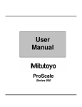
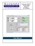
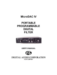
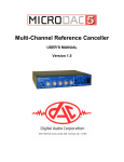
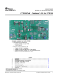
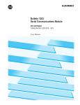
OpenDAC® I/O System
OPEND
AC®
OPENDA
I/O SYSTEM
OpenDAC® I/O System
Grayhill, Inc. • 561 Hillgrove Avenue • LaGrange, Illinois 60525-5997 • USA • Phone: 708-354-1040 • Fax: 708-354-2820 • www.grayhill.com
Contents: OpenDAC
OpenDac® I/O System
OPENDAC® I/O SYSTEM
Low Cost Remote I/O System
FEATURES
• Compatible with Present
Systems
• Communicates within third
party hardware and software
• Ethernet Version
Page
Network Interfaces
OpenDAC® for Ethernet .............................................................................................. 2
OpenDAC® for Modbus .............................................................................................. 4
OpenLT (Optomux) ..................................................................................................... 6
OpenDAC® for Profibus ............................................................................................. 8
Racks
16 Channel ............................................................................................................... 10
OpenDAC® I/O System
OpenDAC® I/O System
The OpenDAC® family is a compact, low cost
and flexible I/O system that is used for remote
data requisition and control. Each network
interface is capable of interfacing with one or
two OpenDAC® I/O racks that allow a
maximum of 32 channels of OpenLine® I/O
modules. With the exception of the OpenLT™,
they do not have the capability of running
embedded control programs (ECPS). If this
is a requirement, please review the OpenLine®
Control System. OpenDAC® I/O racks are
not compatible with the OpenLine ®
Controllers.
Grayhill, Inc. • 561 Hillgrove Avenue • LaGrange, Illinois 60525-5997 • USA • Phone: 708-354-1040 • Fax: 708-354-2820 • www.grayhill.com
OpenDAC
1
OpenDAC® I/O System
NETWORK INTERFACES
OpenDAC® for Ethernet
FEATURES
• Use Ethernet to Control/Monitor up
to 32 Analog and/or Digital I/O
Channels using OpenLine® I/O
Modules
• Network Multiple OpenDACs®
• 10Base-T and 100Base-TX Support
• Extremely Fast Response Times
over Network
• Support Modbus/TCP Protocol
and HTTP
• Use Web Browser for Configuration,
Monitoring and Control of I/O
modules
• Diagnostic LEDs
• CE Certified
• DIN Rail Mounting
• Modbus TCP
ETHERNET UNIT ON OPENDAC® SYSTEM
GENERAL DESCRIPTION
APPLICATIONS
Stand Alone Control
Local Control & I/O
Remote I/O
Distributed I/O
SCADA
RTU
OpenDAC® I/O System
The OpenDAC® for Ethernet network interface is a remote slave that responds to
Modbus/TCP commands that it receives over
the network. The status and configuration of
up to 32 OpenLine® analog or digital I/O channels is stored and constantly refreshed.
OpenDAC® for Ethernet is self-configuring. On
power up, the controller will identify the types
of I/O modules present. The unit will then continuously scan and update the digital and analog modules. Digital input channels can be
setup for latching operation. The OpenDAC®
for Ethernet supports the OpenLine® Smart
Module Protocol (SMP) that allows field calibration and parameter setup of I/O modules.
Each OpenDAC® or third party device on the
network is assigned a unique IP address. There
are three methods of assigning the internet
protocol address -BOOTP, DHCP, and a static
method. The controller is shipped with the default
IP address of 128.0.0.1. The IP address can be
changed using a web browser. The web browser
can also be used to select BOOTP or DHCP to
assign the IP address. Communication data
rates are either 10 Mbps or 100 Mbps.
OpenDAC® automatically detects whether it is
connected to a 10Base-T or 100Base-TX
network, eliminating switch settings and
simplifying set up. Network and controller status
can be monitored by status LEDs.
Each OpenDAC® incorporates a communication
watchdog timer that monitors communication
from the Modbus/TCP master. When the
watchdog is enabled and the slave does not
receive a valid Modbus/TCP message within a
specified time, the OpenDAC® will set all output
modules to the stored fault-state values. Should
a valid message be received, the timer is reset
and communication resumes. All configuration
parameters are displayed and modified using a
web browser. The configuration parameters
are password protected to provide security
against unauthorized access.
ANALOG & DIGITAL I/O
MODULES
OpenDAC® for Ethernet connects directly to
one or two 16 channel racks. Any combination
of analog and digital I/O modules may be used.
On power up, the OpenDAC® scans and stores
the I/O configuration and makes the information
available to the master.
In addition to simple On/Off instructions, the
OpenDAC® allows you to:
• Read linearized thermocouple and RTD
temperature values
• Detect rising or falling edges
• Latch momentary input events
• Set the level of analog outputs
OpenDAC
2
Grayhill, Inc. • 561 Hillgrove Avenue • LaGrange, Illinois 60525-5997 • USA • Phone: 708-354-1040 • Fax: 708-354-2820 • www.grayhill.com
OpenDAC® I/O System
DIMENSIONS
In inches (and millimeters)
4.1(104,26)
3.9 (99,56)
LINK
STAT
POWER
CONFIG
RESET
DEFAULT
OpenDAC
for Ethernet
DIN RAIL LATCH
2.6
(65.48)
2.3 (57.17)
TO CENTERLINE OF
DIN RAIL CHANNEL
PIN 1
SPECIFICATIONS
Supply Voltage: 4.80 to 5.25 Vdc
Supply Current (less modules): 1.0 amp
max.
Operating Temperature: -40 to 85°C
Humidity: 5-95% non-condensing
Housing Material: ABS/Polycarbonate blend
CPU: Net+ARM 40
Connections:
Network: RJ-45
Passive Rack: 48-Pin Euro DIN (male)
Range of Network (without repeaters):
100 meters with CAT 5 UTP
ORDERING INFORMATION
Part Number
Description
Ethernet Network Interface
72-ETH-T000
Analog/Digital OpenDAC® for Ethernet
Ethernet User’s Manual and Software
72-UM-OETH
72-UM-ETH
72-UOL
72-UME-DLL32
OpenDAC® for Ethernet user’s manual
OpenLine® for Ethernet user’s manual
OpenLine®/OpenDAC® configuration and product data
Ethernet/Modbus DLL for Windows 95/98/NT
OpenDAC I/O Racks
Digital OpenLine® I/O Modules
Analog OpenLine® I/O Modules
Power Supply
Available from your local authorized
Grayhill Distributor. For prices and discounts,
contact your local sales office, an authorized
Distributor or Grayhill.
Grayhill, Inc. • 561 Hillgrove Avenue • LaGrange, Illinois 60525-5997 • USA • Phone: 708-354-1040 • Fax: 708-354-2820 • www.grayhill.com
OpenDAC
3
OpenDAC® I/O System
Compatible Components
®
OpenDAC® I/O System
NETWORK INTERFACES
OpenDAC® for Modbus
FEATURES
• Each Unit Controls/Monitors up to
32 Analog and/or Digital I/O using
OpenLine® Modules
• Network up to 247 OpenDACs® per
Host PC, Each Separated by as
much as 4,000 Feet
• Communicate Over RS-422/485 at
Speeds from 9600 Baud to 56.7 KB
• 100% Modbus ASCII or Modbus
RTU Compatible
• CE Certified
• DIN Rail or Panel Mount
MODBUS UNIT ON OPENDAC® SYSTEM
APPLICATIONS
GENERAL DESCRIPTION
Stand Alone Control
Local Control & I/O
Remote I/O
Distributed I/O
SCADA
OpenDAC® I/O System
RTU
OpenDAC® for Modbus is an inexpensive,
flexible interface to 32 analog or digital
OpenLine® I/O. As one of 247 slave devices on
a Modbus network, OpenDAC® for Modbus
constantly scans and stores the current status
of each I/O. Upon command from the host
device, the controller will change the status of
an output or return the value of an input. The
slave address is switch selectable. Diagnostic
LEDs provide troubleshooting assistance.
ANALOG & DIGITAL I/O
OpenDAC® for Modbus connects directly to two
16 channel racks. Any combination of analog
and digital I/O modules may be used. On power
up, the OpenDAC® scans and stores the I/O
configuration and makes the information
available to the master for query.
In addition to simple On/Off instructions, Modbus
commands allow you to:
• Read linearized thermocouple and RTD
temperature values
• Count pulses at frequencies up to 1000Hz
• Detect rising or falling edges
• Latch momentary input events
• Set the level of analog outputs
COMMUNICATIONS
format to code the command and the response
messages. Application programs running on
the host computer issue commands and then
await responses from the OpenDAC®. The
communications speed is switch selectable
between 9600 and 56700 baud. The entire
network can span 4000 feet.
FAULT TOLERANCE
Each OpenDAC® for Modbus has an internal
communications watchdog timer to minimize
the impact of a broken Modbus link between the
controller and the master device. If activated,
the timer must be reset by an incoming message
within the prescribed period of time. If not, the
controller will force it’s outputs into a default
state.
SOFTWARE
Software drivers are available which simplify
the task of interfacing host programs written in
Visual Basic or C to the Modbus network. Sample
programs, set-up and debug utilities are included
on the disk with the drivers. Interface drivers for
most third party software packages are available
through their distributors. Our DLL will assist
you in building custom Man-Machine Interfaces
using Visual Basic, Visual C/C++, or Borland
compilers running on Windows 95, 98 or NT.
The host computer and OpenDAC® for Modbus
communicate serially over one or two pair of
twisted wires per RS-422/485 in a multi-drop
configuration. They use Modbus ASCII or RTU
OpenDAC
Grayhill, Inc. • 561 Hillgrove Avenue • LaGrange, Illinois 60525-5997 • USA • Phone: 708-354-1040 • Fax: 708-354-2820 • www.grayhill.com
4
OpenDAC® I/O System
DIMENSIONS
In inches (and millimeters)
4.1(104.26)
1.1
(28.22)
3.9 (99.56)
DIN RAIL LATCH
1.0
(25.86)
3.0
(75.69)
2.6
(65.48)
2.3 (57.17)
TO CENTERLINE OF
DIN RAIL CHANNEL
PIN 1
SPECIFICATIONS
ORDERING INFORMATION
Part Number
Description
OpenDAC® Network Interface
72-MOD-4000
Analog/Digital OpenDAC® for Modbus
OpenDAC® User’s Manual and Software
72-UM-OMOD
72-UME-DLL32
72-UOL
OpenDAC® for Modbus user’s manual
Ethernet/Modbus DLL for Windows 95/98/NT
OpenLine® configuration and product data
Compatible Components
®
OpenDAC I/O Racks
Digital OpenLine® I/O Modules
Analog OpenLine® I/O Modules
Power Supply
Available from your local authorized Grayhill
Distributor. For prices and discounts, contact
your local sales office, an authorized Distributor,
or Grayhill.
Grayhill, Inc. • 561 Hillgrove Avenue • LaGrange, Illinois 60525-5997 • USA • Phone: 708-354-1040 • Fax: 708-354-2820 • www.grayhill.com
OpenDAC
5
OpenDAC® I/O System
Power Supply: 4.75 to 5.25 Vdc
Supply Current (less modules): 1 amp @ 5
Vdc max.
Operating Temperature: 0 to 60°C
Humidity: 95% non-condensing
Microprocessor: V25 @ 10 MHz
Housing Material: ABS/Polycarbonate blend
Connections:
RS-422/485: 5 position depluggable connector
Passive Rack: 48-pin Euro DIN (male)
Serial Data:
Format: 10 Bit ASCII: 1 Start, 1 Stop, 8 Data
Integrity: Message Checksum
Range of Network: Compliant with EIA/TIA
RS485-A (1 standard load per controller).
Operates in multi-drop mode. 247 DIP switch
selectable addresses. May require RS485
repeaters for lengths over 4000 feet or more
than 32 controllers. Consult factory for special
configurations.
OpenDAC® I/O System
NETWORK INTERFACES
OpenLT™ (Optomux)
FEATURES
• Each Unit Controls/Monitors up to 32
Analog and/or Digital I/O using OpenLine®
Modules
• Executes On-Board Programs Created
With Borland C
• Network up to 64 OpenLTs per Host Serial
Port, Spanning as Much as 4000 Feet
• Communicate Over RS422 /485 at
Speeds from 9600 Baud to 115.2 KB
• 100% Optomux Compatible, With
Expanded Command Set
• I/O Update Rates of 500 µSec per 32
Digital I/O, and 2 mS per Analog Input
or 2 Analog Outputs
• 64-Bit Floating Point Math
• DIN Rail or Panel Mountable
• CE Certified
APPLICATIONS
Stand Alone Control
Local Control & I/O
Central Processing: Remote I/O
Distributed Processing: Remote I/O
SCADA
OpenDAC® I/O System
RTU
GENERAL DESCRIPTION
The OpenLT™ Optomux™ controller is a remote
slave that responds to Optomux™ commands
from the master or host PC. The 72-OPT-4100
version has memory for Embedded Control
Programs (ECPs) which are control or data
acquisition routines which run locally on the
OpenLT™ and off-load some responsibilities
from the host. ECP routines written for MicroDAC
can be easily transferred to OpenLT™ and vice
versa. By combining MicroDAC, OpenLT™ and
ProMux® the cost/performance of a distributed
control or data acquisition network is optimized
for price and performance.
OPENLT® UNIT ON OPENDAC® SYSTEM
ANALOG & DIGITAL I/O
EMBEDDED CONTROL PROGRAMS
OpenLT® connects directly to one or two
OpenLine® racks (part number 70LRCK16-48).
Any combination of OpenLine® analog and digital
I/O modules may be used. OpenLTs™ can be
networked to a host PC which execute programs
that monitor the input signals and control the
outputs. In addition to simple ON/OFF
instructions, commands are included which
permit you to:
• Sample analog signals at 2 mS per input
• Flag values above or below prescribed levels
• Capture min/max values
• Calculate the average input signal levels
• Provide linearized thermocouple and
RTD temperature values
• Determine the width of input pulses
• Count pulses at frequencies up to 1000Hz
• Detect rising or falling edges
• Latch momentary input events
• Set the level of analog outputs
• Provide delayed-on or delayed-off outputs
By specifying OpenLT(s)® with the optional 64
KB of flash memory, you can develop and
download C language programs to any of the
networked controllers.
COMMUNICATIONS
™
The host computer and OpenLT(s)
communicate serially over one or two pair of
twisted wires per RS-422/485 in a multi-drop
configuration. They use Optomux™ ASCII format
to code the command and the response
messages. Application programs running on
the host computer issue commands and then
await responses from the OpenLT™. The
communications speed is selectable between
9.6 and 115.2 KBaud. Each controller on the
network is assigned a unique base address.
The entire network can span 4000 feet.
Diagnostic LEDs show traffic on the network.
Even while an ECP is running on OpenLT®, any
Optomux™ command it receives from the host
will be processed as usual, which allows you to
delegate some or all of the control and data
acquisition responsibility from the host computer.
This reduces communications time and improves
system response.
For embedded or stand-alone applications,
downloaded ECP routines can be initiated on
power-up.
Libraries and the appropriate download utility
are included with the ECP Programmers Manual.
SOFTWARE
Software drivers are available which simplify
the task of interfacing host programs written in
Visual Basic or C to the Optomux network.
Sample programs, set-up and debug utilities
are included on the disk with the drivers. Interface
drivers for most third party software packages
are available through their distributors. Our
Optomux DDE Server dramatically simplifies
data sharing between OpenLTs™ and Windows
applications, such as Microsoft EXCEL (see
Controller Software). Our DLL will assist you in
building custom Windows Man-Machine
Interfaces using Visual Basic, Visual C/C++, or
Borland compilers.
OpenDAC
Grayhill, Inc. • 561 Hillgrove Avenue • LaGrange, Illinois 60525-5997 • USA • Phone: 708-354-1040 • Fax: 708-354-2820 • www.grayhill.com
6
OpenDAC® I/O System
DIMENSIONS
In inches (and millimeters)
4.1(104.26)
1.1
(28.22)
3.9 (99.56)
DIN RAIL LATCH
1.0
(25.86)
3.0
(75.69)
2.6
(65.48)
2.3 (57.17)
TO CENTERLINE OF
DIN RAIL CHANNEL
PIN 1
SPECIFICATIONS
ORDERING INFORMATION
Part Number
Description
OpenLT® Network Interface
72-OPT-4000
72-OPT-4100
Analog/Digital OpenLT®
Analog/Digital OpenLT® with 64K flash for C ECP storage
OpenLT® User’s Manuals and Software
72-UMM-D
72-UMM-DDE
72-UMM-DLL
72-UMM-DLL32
72-UMM-E
72-UMM-H
72-UM-OOPT
72-UOL
7W-UM-MDL32
Driver development and protocol definition (includes driver source code)
Optomux DDE server for Windows 3.1
Optomux DLL for Windows 3.1
Optomux DLL for Windows 95/98/NT
C language ECP manual with libraries
Programmer’s manual with Basic and C host drivers and examples
Hardware installation and setup. Includes setup and debug programs
OpenLine® configuration and product data
Windows ECP download Utility
Compatible Components
OpenDAC® I/O Racks
Digital OpenLine® I/O Modules
Analog OpenLine® I/O Modules
Power Supplies
Available from your local authorized Grayhill
Distributor. For prices and discounts, contact
your local sales office, an authorized Distributor or
Grayhill.
Grayhill, Inc. • 561 Hillgrove Avenue • LaGrange, Illinois 60525-5997 • USA • Phone: 708-354-1040 • Fax: 708-354-2820 • www.grayhill.com
OpenDAC
7
OpenDAC® I/O System
Power Supply: 4.75 to 5.25 Vdc
Supply Current (less modules): 300 mA max.
Operating Temperature: 0 to 60°C
Humidity: 95% non-condensing
Microprocessor: V25 @ 10 MHz
Housing Material: ABS/Polycarbonate blend
Connections:
RS-422/485: 5 position pluggable terminal block
Rack: 48-pin Euro DIN (male)
Serial Data:
Format: 10-Bit ASCII, 1 Start, 1 Stop, 8 Data
Integrity: Message Checksum or 4 Pass + CS
Range of Network: Compliant with EIA/TIA
RS485-A (1 standard load per controller).
Operates in multi-drop mode. 64 DIP switch
selectable addresses. May require RS485
repeaters for lengths over 4000 feet or more
than 32 controllers. Consult factory for special
configurations.
OpenDAC® I/O System
NETWORK INTERFACES
OpenDAC® for Profibus
FEATURES
• Each Unit Controls/Monitors up to
32 Analog and/or Digital I/O using
OpenLine® Modules
• Network up to 127 OpenDACs®
per Host PC
• Communicate at Speeds
Up to12 MB
• Auto Baud Rate Detect
• 100% Profibus DP Compatible
(PTO Tested and Approved)
• I/O Update Rates of 500 µSec per
32 Digital and 1 mS per Analog
Module (2 Channels)
• Diagnostic LEDs
• CE Certified
• DIN Rail Mount
APPLICATIONS
PROFIBUS UNIT ON OPENDAC® SYSTEM
GENERAL DESCRIPTION
Stand Alone Control
Local Control & I/O
Remote I/O
Distributed I/O
OpenDAC® I/O System
SCADA
RTU
The OpenDAC® for Profibus network interface
is a remote slave that responds to Profibus DP
commands that it receives over the network.
The status and configuration of up to 32
OpenLine® analog or digital I/O channels is
stored and constantly refreshed.
OpenDAC® for Profibus is self-configuring. On
power up, the controller will read the ID of each
I/O module and build an internal database.
During the master configuration the controller
will compare this configuration with the stored
configuration. If there is a match, the master will
allow exchange of information to occur.
Each OpenDAC® or third party device on the
network will occupy 1 of 127 unique addresses.
Communication between the master and slave
devices takes place at baud rates from 50 KB to
12 MB. OpenDACs® automatically detect the
baud rate, eliminating switch settings and
simplifying set up. Network traffic and controller
status can be monitored by status LEDs on the
controllers. Diagnostic information is routinely
exchanged between master and slave devices.
Each OpenDAC® incorporates a communication
watchdog timer that monitors communication
from the Profibus master. When the watchdog
is enabled and the slave does not receive a valid
Profibus message within 100 mS, the OpenDAC®
will set all output values to zero. Should a valid
message be received, the timer is reset and
communication resumes.
OpenDAC
Grayhill, Inc. • 561 Hillgrove Avenue • LaGrange, Illinois 60525-5997 • USA • Phone: 708-354-1040 • Fax: 708-354-2820 • www.grayhill.com
8
OpenDAC® I/O System
DIMENSIONS
In inches (and millimeters)
4.20 (106,68)
DIN RAIL LATCH
3.90 (99,06)
1.0 (25,4)
2.90
(73,66)
2.60
(66,04)
2.31 (58,75)
TO CENTERLINE
OF DIN RAIL
CHANNEL
PIN #1
SPECIFICATIONS
ORDERING INFORMATION
Part Number
Description
Profibus Network Interfacer
72-PRO-4000
Analog/Digital OpenDAC® for Profibus DP
Profibus User’s Manual and Software
72-UM-PRO
72-UOL
OpenDAC® for Profibus DP user’s manual
OpenLine® configuration and product data
Available from your local authorized
Grayhill Distributor.
For prices and discounts, contact your local
sales office, an authorized Distributor, or
Grayhill.
Grayhill, Inc. • 561 Hillgrove Avenue • LaGrange, Illinois 60525-5997 • USA • Phone: 708-354-1040 • Fax: 708-354-2820 • www.grayhill.com
OpenDAC
9
OpenDAC® I/O System
Supply Voltage: 4.75 to 5.25 Vdc
Supply Current (less modules): 0.5A max.
Operating Temperature: -40 to 85°C
Humidity: 5-95% non-condensing
Housing Material: ABS/Polycarbonate blend
CPU: AM 188ES @ 24 MHz
Connections:
Profibus: 9-Pin D-Sub (female)
Passive Rack: 48-Pin Euro DIN (male)
Serial Data:
Format: 11 bits: 1 start, 1 stop, 1 parity (even),
8 data
Integrity: Frame checksum
Range of Network (without repeaters):
1200 meters for entire network below 93 KB;
600 meters at 187.5 KB; 200 meters at 500 KB
OpenDAC® I/O System
RACKS
16 Channel
FEATURES
• Automatically Detects OpenLine®
I/O Module Types
• Provides Direct Interface for the I/O to
OpenDAC® Network Interfaces
• Multiple Termination Options
• Stack up to Two Racks for the
32 I/O channels
• Small Footprint
• DIN Rail Mount
• UL, CSA, CE (See Engineering Info, p. L-6)
16 CHANNEL RACK: OpenDAC® Rack
Part No. 70LRCK16-48
Dimensions are shown in inches
(and millimeters).
All tolerances are ± 0.010 (0,25)
unless otherwise specified.
PIN 1
J4
2.8
(72.21)
6.2
(156.87)
5.9
(149.66)
J1 TOP ROW: +5V
BOTTOM ROW: GND
70LRCK16-48P
3.9
(99.85)
I/O BUS
PIN 1
J4
M8
M7
M6
M5
M4
M3
M2
M1
OpenDAC® I/O System
4.4
(111.56)
(WP VERSION SOLD
WITH PLUGS)
1
3
5
7
9
11
13
15
17
19
21
23
25
27
29
31
2
4
6
8
10
12
14
16
18
20
22
24
26
28
30
32
+5 +5
1
3
2
DIN RAIL CLIP
5
4
7
6
9 11 13 15 17 19 21 23 25 27 29 31
2.8
(72.21)
8 10 12 14 16 18 20 22 24 26 28 30 32
J1 TOP ROW: +5V
BOTTOM ROW: GND
70LRCK16-48
OpenDAC
Grayhill, Inc. • 561 Hillgrove Avenue • LaGrange, Illinois 60525-5997 • USA • Phone: 708-354-1040 • Fax: 708-354-2820 • www.grayhill.com
10
OpenDAC® I/O System
SCHEMATIC: Part No. 70LRCK16-48
+5
+5
1
3
2
J2
5
4
7
6
9
8
11
10
13
12
15
14
17
16
19
18
21
20
23
22
25
24
27
26
29
28
31
30
32
FIELD
WIRING
TERMINAL
STRIP
1
2
3
4
B1
B2
B14
0
1
2
3
4
5
6
7
MODULE
LOCATION
J2
5
6
7
8
9
B3
B15
B16
J3
B1
B2
B14
J2
J2
J2
J3
C9
C10
C11
C12
C13
C14
C15
C16
A9
A10
A11
A12
A13
A14
A15
A16
C1
C2
C3
C4
C5
C6
C7
C8
A1
A2
A3
A4
A5
A6
A7
A8
B4
B5
B9
C8
C7
C6
C5
C4
C3
C2
C1
A8
A7
A6
A5
A4
A3
A2
A1
B13
B12
B4
J3
J2
C9
C10
C11
C12
C13
C14
C15
C16
B6
B7
B8
B10
B11
B12
B13
J3
B5
B6
B7
B8
B9
B10
B11
ORDERING INFORMATION
Part Number
J3
B3
B15
B16
I/O
J3
/CS1
ISCLK
IDI
/ICONV
MODULE
ID
DETECT
A9
A10
A11
A12
A13
A14
A15
A16
/CS2
/IDOR
IDO
IEOC
(MODULES ORDERED SEPARATELY)
Description
UL
CSA
Style
16 Channel Racks
70LRCK16-48
70LRCK16-48C
16
16
70LRCK16-48P
16
70LRCK16-48WP
16
X
X
X
X
OpenDAC®
OpenDAC®
X
X
OpenDAC®
X
X
OpenDAC®
OpenDAC® I/O System
48-pin Euro DIN logic signal connector. DIN rail mount.
48-pin Euro DIN logic signal connector. DIN rail mount with
cage clamp style terminal blocks
48-pin Euro DIN logic signal connector. DIN rail mount with
pluggable terminal blocks
48-pin Euro DIN logic signal connector. DIN rail mount with
pluggable terminal blocks, plug included
Available from your local Grayhill
Distributor. For prices and discounts, contact
a local Sales Office, an authorized local
Distributor or Grayhill.
Grayhill, Inc. • 561 Hillgrove Avenue • LaGrange, Illinois 60525-5997 • USA • Phone: 708-354-1040 • Fax: 708-354-2820 • www.grayhill.com
OpenDAC
11
System 50
SYSTEM 50
System 50
Grayhill, Inc. • 561 Hillgrove Avenue • LaGrange, Illinois 60525-5997 • USA • Phone: 708-354-1040 • Fax: 708-354-2820 • www.grayhill.com
Contents: System 50
SYSTEM 50
• MicroDAC
• MicroDAC LT
• Promux
• Microlon
• Various I/O Racks
Page
Grayhill, Inc. • 561 Hillgrove Avenue • LaGrange, Illinois 60525-5997 • USA • Phone: 708-354-1040 • Fax: 708-354-2820 • www.grayhill.com
System 50
2
System 50
SYSTEM 50 RACKS OVERVIEW ................................................................ 3
Racks
4 Channel ...................................................................................................... 4
8 Channel ...................................................................................................... 6
16 Channel .................................................................................................. 11
24 Channel (In-Line) ................................................................................... 18
24 Channel .................................................................................................. 22
32 Channel .................................................................................................. 25
32 Channel Parallel Controller Board for 72-PMX-32D ............................ 27
Controllers
MicroDAC (Optomux) .................................................................................. 29
MicroDAC LT (Optomux) ............................................................................. 31
Network Interfaces
Promux (Optomux) ...................................................................................... 33
Parallel Bus Interface .................................................................................. 35
Communication Converters ........................................................................ 37
Accessories ................................................................................................. 38
System 50
CONTROLLERS
MicroDAC (Optomux)
FEATURES
• Each Unit Controls/Monitors up to
32 Analog (G5 Only) and/or Digital
I/O Modules
• Executes On-Board Programs
Created With Borland C
• Network up to 64 MicroDACs per
Host Serial Port, Each Separated
by as Much as 4000 Feet
• Communicate Over RS-422/485 at
Speeds From 1200 Bd to 115.2 KB
• 100% Optomux™ Compatible, With
Expanded Command Set
• I/O Update Rates of 500 µSec per
32 Digital I/O, and 10 mS per
Analog Input or 2 Analog Outputs
• BASIC and C Drivers for the PC
• DIN Rail or Panel Mountable Metal
Enclosure
• Hardware Expansion With SBX Port
• Real Time Clock Option (Y2K
Compliant)
APPLICATIONS
Stand Alone Control
Local Control & I/O
Remote I/O
Distributed I/O
SCADA
RTU
ANALOG & DIGITAL I/O
System 50
A 50 conductor ribbon cable is supplied to connect
MicroDACs to any 8,16,24, or 32 module
mounting rack. If connected to a G5 rack, any
combination of analog and digital I/O modules
may be used. OpenLine®, standard and mini
racks permit only a combination of digital modules.
MicroDACs can be networked to a PC which
runs programs that monitor the input signals and
control the outputs. In addition to simple ON/OFF
instructions, commands are included which
permit you to:
• Sample analog signals at 10 mS per input
• Flag values above or below prescribed levels
• Capture min/max values
• Calculate the average input signal levels
• Provide linearized thermocouple and
RTD temperature values
• Determine the width of input pulses
• Count pulses at frequencies up to 1000 Hz
• Detect rising or falling edges
• Latch momentary input events
• Set the level of analog outputs
• Provide delayed-on or delayed-off outputs
COMMUNICATIONS
The host PC and MicroDAC(s) communicate
serially over one or two pair of twisted wires per
RS-422/485 in either a multi-drop or repeat
configuration. They use Optomux™ ASCII format
to code the command and the response
messages. Application programs running on the
host PC issue commands and then await
responses from the MicroDAC. The
communications speed is selectable between
1.2 and 115.2 KBaud. Each controller on the
network is assigned a unique base address. You
can separate units from one another by as much
as 4,000 feet.
EMBEDDED CONTROL
PROGRAMS
By specifying MicroDAC(s) with the optional
64KB of flash memory, you can develop and
download C language programs to any of the
networked controllers.
Even while an Embedded Control Program (ECP)
is running on MicroDAC, any Optomux ™
command it receives from the host will be
processed as usual, which allows you to delegate
some or all of the control and data acquisition
responsibility from the host PC. This reduces
communications time and improves system
response.
For embedded or stand-alone applications,
downloaded ECP routines can be initiated on
power-up. Where redundant control or process
shutdown procedures are vital, ECP initiation can
be tied to the communications watchdog timer. In
the event the host computer goes off line, the ECP
automatically begins executing.
Libraries and the appropriate download utility are
included with the ECP Programmers Manual.
SOFTWARE
Software drivers are available which simplify the
task of interfacing host programs written in Visual
Basic or C. Sample programs, set-up and debug
utilities are included on the disk with the drivers.
Interface drivers for most third party software
packages are available through their distributors.
Our MicroDAC DDE Server dramatically
simplifies data sharing between MicroDACs and
Windows applications, such as Microsoft Excel
(see Optomux Software). Our DLL will assist you
in building custom Windows Man-Machine
Interfaces or control programs using Visual Basic,
Visual C/C++, or Borland compilers.
OTHER FEATURES/OPTIONS
The RS-232 serial port provides a connection for
remote RS-232 devices. You can use this port to
read information from input devices such as bar
code readers or keyboards or to write information
to output devices such as operator interfaces,
intelligent displays or printers.
The optional real time clock permits ECP routines
to be executed based on date or time of day. It
also allows data that is collected to be time
stamped and stored in battery backed RAM
memory.
System 50
Grayhill, Inc. • 561 Hillgrove Avenue • LaGrange, Illinois 60525-5997 • USA • Phone: 708-354-1040 • Fax: 708-354-2820 • www.grayhill.com
29
System 50
DIMENSIONS
In inches (and millimeters)
9 PIN D-SUB FOR RS-232
CONNECTION
7.885 (200,28)
THUMB SCREW FOR COVER
REMOVAL (2 PLACES)
T
V
RC
XM
R
RO
ER
CO
P
5.745 (145,92)
ATTACHES TO
35 MM DIN RAIL
EN50022
6.370
(161,80)
5.105
(129,67)
D A T A
A C Q U I S I T I O N
A N D
C O N T R O L
3.857
(97,97)
2.402
(61,01)
.632
(16,05)
2.843
(72,21)
.560
(14,2)
DIN RAIL CLIP
6.755 ± .005
(171,58 ± 0,13)
PANEL MOUNTING HOLES I.D. 0.18 (4,6) DIA. (2 PLACES)
MOUNT WITH #8 SCREWS 0.75 (19,05) LONG MIN.
CONNECTION
FOR
RS-422/485
WIRES
0.719
(18,26)
Unless otherwise specified, tolerances are ± .010 (0,25).
SPECIFICATIONS
ORDERING INFORMATION
Part Number
Description
72-MDC-32ADC
Analog/Digital MicroDAC with RS-232 and SBX ports, 64K batt.
backed RAM, 64K flash for C ECP storage, and real time clock.
MicroDAC Controllers
System 50
Power Supply: 4.75 to 5.25 Vdc
Supply Current (less modules): 1A maximum
Operating Temperature: 0 to 60°C
Humidity: 95% non-condensing
Housing Material: Anodized Aluminum
Microprocessor: V25 @ 10 MHz
Connections:
RS-422/485: 12 position terminal block
RS-232 (DCE or DTE): 9-pin D-Sub (male)
SBX: 36-pin dual row (female)
Rack: 50-pin male header
Serial Data:
Format: 10-Bit ASCII, 1 Start, 1 Stop, 8 Data
Integrity: Message Checksum or 4 Pass + CS
Range of Network: Compliant with EIA/TIA
RS-485-A (1 standard load per controller).
Operates in multi-drop or repeat mode. 64 DIP
switch selectable addresses. May require
RS485 repeaters for lengths over 4,000 feet
or more than 32 controllers in multi-drop
mode. Consult factory for special configurations.
MicroDAC User's Manuals and Software
72-UMM
72-UMM-D
72-UMM-DDE
72-UMM-DLL
72-UMM-DLL32
72-UMM-E
72-UMM-H
72-UMM-IL
7W-UM-MDL32
Introduction to MicroDAC
Driver development and protocol definition. Includes driver source code
Optomux DDE Server for Windows 3.1
Optomux DLL for Windows 3.1
Optomux DLL for Windows 95/98/NT
C language ECP manual with libraries
Programmers manual with Basic and C host drivers & examples
Hardware installation and set-up. Includes set-up and debug programs.
Windows ECP download Utility
Available from your local authorized
Grayhill Distributor.
For prices and discounts, contact your local
sales office, an authorized Distributor, or
Grayhill.
Grayhill, Inc. • 561 Hillgrove Avenue • LaGrange, Illinois 60525-5997 • USA • Phone: 708-354-1040 • Fax: 708-354-2820 • www.grayhill.com
System 50
30
System 50
CONTROLLERS
MicroDAC LT (Optomux)
FEATURES
• Each Unit Controls/Monitors up to
32 Analog (G5 Only) and/or Digital
I/O Modules
• Executes On-Board Programs
Created With Borland C
• Network up to 64 MicroDAC LTs
per Host Serial Port, Spanning as
Much as 4000 Feet
• Communicate Over RS-422 /485 at
Speeds From 1200 Baud to
115.2 KB
• 100% Optomux Compatible, With
Expanded Command Set
• I/O Update Rates of 500 µSec per
32 Digital I/O, and 10 mS per
Analog Input or 2 Analog Outputs
• 64-Bit Floating Point Math
APPLICATIONS
GENERAL DESCRIPTION
System 50
MicroDAC LT is a low cost version of MicroDAC
for customers who don't need all of the features
of MicroDAC. Missing are the battery back-up
for the RAM memory, real-time clock, RS-232,
and SBX ports. The DIN Rail Mountable metal
enclosure is optional. ECP routines written for
MicroDAC can be easily transferred to
MicroDAC LT and vice versa. By combining
MicroDAC, MicroDAC LT and ProMux the
cost/performance of a distributed control or
data acquisition network is optimized for price
and performance.
ANALOG & DIGITAL I/O
MicroDAC LT connects directly to any 8,16,24,
or 32 module mounting rack with a 50-pin
header. If connected to a G5 rack, any
combination of analog and digital I/O modules
may be used. Standard and Mini racks permit
only a combination of digital modules. MicroDAC
LTs can be networked to a host PC which
execute programs that monitor the input signals
and control the outputs. In addition to simple
ON/OFF instructions, commands are included
which permit you to:
• Sample analog signals at 10 mS per input
• Flag values above or below prescribed levels
• Capture min/max values
• Calculate the average input signal levels
• Provide linearized thermocouple and
RTD temperature values
• Determine the width of input pulses
• Count pulses at frequencies up to 1000Hz
• Detect rising or falling edges
• Latch momentary input events
• Set the level of analog outputs
• Provide delayed-on or delayed-off outputs
Even while an Embedded Control Program
(ECP) is running on MicroDAC LT, any
Optomux™ command it receives from the host
will be processed as usual, which allows you to
delegate some or all of the control and data
acquisition responsibility from the host computer.
This reduces communications time and
improves system response.
For embedded or stand-alone applications,
downloaded ECP routines can be initiated on
power-up.
Libraries and the appropriate download utility
are included with the ECP Programmers
Manual.
COMMUNICATIONS
The host computer and MicroDAC LT(s)
communicate serially over one or two pair of
twisted wires per RS-422/485 in a multi-drop
configuration. They use Optomux ™ ASCII
format to code the command and the response
messages. Application programs running on
the host computer issue commands and then
await responses from the MicroDAC. The
communications speed is selectable between
1.2 and 115.2 KBaud. Each controller on the
network is assigned a unique base address.
The entire network can span 4000 feet.
EMBEDDED CONTROL PROGRAMS
By specifying MicroDAC LT(s) with the optional
64KB of flash memory, you can develop and
download C language programs to any of the
networked controllers.
SOFTWARE
Software drivers are available which simplify
the task of interfacing host programs written in.
Visual Basic or C to the MicroDAC network.
Sample programs, set-up and debug utilities
are included on the disk with the drivers.
Interface drivers for most third party software
packages are available through their
distributors. Our MicroDAC DDE Server
dramatically simplifies data sharing between
MicroDACs and Windows applications, such
as Microsoft Excel (see Controller Software).
Our DLL will assist you in building custom
Windows Man-Machine Interfaces or control
programs using Visual Basic, Visual C/C++, or
Borland compilers.
1
With optional enclosure.
System 50
Grayhill, Inc. • 561 Hillgrove Avenue • LaGrange, Illinois 60525-5997 • USA • Phone: 708-354-1040 • Fax: 708-354-2820 • www.grayhill.com
31
System 50
DIMENSIONS
In inches (and millimeters)
STANDOFF I.D.
0.15 (3,8) DIA.
CLEARANCE
FOR #6 SCREW
4.975
(126,37)
0.725
(18,42)
ATTACHES TO
35 MM DIN RAIL
EN50022
+5V
GND
FH+
FHTH+
THFO+
FOTO+
TO-
4.25
(107,95)
0.725
(18,42)
0.20
(5,08)
4.875
(123,83)
2.20
(55,9)
3.000
(76,2)
2.80
(71,12)
0.625
(15,88)
.758
(19,25)
.758
(19,25)
1.385
(35,18)
PLUG CONNECTOR
MATES DIRECTLY
WITH A RACK
Unless otherwise specified, tolerances are ± .010 (0,25).
Power Supply: 4.75 to 5.25 Vdc
Supply Current (less modules): 300 mA
Operating Temperature: 0 to 70°C
Humidity: 95% non-condensing
Microprocessor: V25 @ 10 MHz
Housing Material: Painted steel
Connections:
RS-422/485: 10 position terminal block
Rack: 50-pin female plug
Serial Data:
Format: 10-Bit ASCII, 1 Start, 1 Stop, 8 Data
Integrity: Message Checksum or 4 Pass + CS
Range of Network: Compliant with EIA/TIA
RS485-A (1 standard load per controller).
Operates in multi-drop mode. 64 DIP switch
selectable addresses. May require RS485
repeaters for lengths over 4000 feet or more
than 32 controllers. Consult factory for special
configurations.
ORDERING INFORMATION
Part Number
System 50
SPECIFICATIONS
Description
MicroDAC LT Controllers
72-MDL-32ADC
Analog/Digital with 64K flash for C ECP storage
MicroDAC LT User's Manuals and Software
72-UMM
72-UMM-D
72-UMM-DDE
72-UMM-DLL
72-UMM-DLL32
72-UMM-E
72-UMM-H
72-UMM-IL
Introduction to MicroDAC
Driver development and protocol definition. Includes driver source code
Optomux DDE Server for Windows 3.1
Optomux DLL for Windows 3.1
Optomux DLL for Windows 95/98/NT
C language ECP manual with libraries
Programmers manual with Basic and C host drivers & examples
Hardware installation and set-up. Includes set-up and debug programs
Available from your local authorized Grayhill Distributor.
For prices and discounts, contact your local
sales office, an authorized Distributor, or
Grayhill.
Grayhill, Inc. • 561 Hillgrove Avenue • LaGrange, Illinois 60525-5997 • USA • Phone: 708-354-1040 • Fax: 708-354-2820 • www.grayhill.com
System 50
32
System 50
NETWORK INTERFACES
ProMux® (Optomux)
FEATURES
• Each Board Controls Up to 24
Standard, Mini, G5 or OpenLine®
Digital Modules
• Up to 256 Addressable ProMux®
Boards Separated by 4,000 Feet
• 100% Optomux Compatible,
Plus Extra Commands
• Communications at Speeds From
300 Baud to 38.4 KBaud.
• Transient Protection on
Communications Lines
• Direct Plug-In or Ribbon
Cable Interconnection
• BASIC and C Drivers for the PC
APPLICATIONS
Stand Alone Control
Local Control & I/O
Remote I/O
Distributed I/O
SCADA
RTU
System 50
DIGITAL INPUTS/OUTPUTS
The ProMux® network interface mates with
any of our 8, 16, or 24 digital module racks.
Plug Grayhill OpenLine®, standard, miniature,
or G5 digital I/O modules into the racks. They
can be mixed in any combination. Connect the
ProMux® boards serially to a host computer
and then issue commands to monitor the
inputs or control the outputs. Commands are
included which permit you to:
• Read the ON/OFF status of inputs
• Determine the width of input pulses
SOFTWARE
•
•
•
•
Count pulses at frequencies up to 400Hz
Detect rising or falling edges
Latch momentary input events
Turn outputs ON or OFF individually or in
groups
• Pulse-width modulate outputs
• Provide delayed-on or delayed-off outputs
• Generate pulses or squarewaves
COMMUNICATIONS
The host computer and ProMux ® boards
communicate serially over two pair of twisted
wires per RS-422/485 in either a multi-drop or
repeat configuration. They use an industry
standard ASCII string format to code the
command and response messages.
Application programs running on the host
computer issue commands and then await
responses from the ProMux ® boards. The
communications speed is selectable between
300 baud and 38.4 KBaud. Each controller on
the network is assigned a unique base address
from 0 to 255. You can separate boards from
one another by as much as 4,000 feet.
Software drivers are available which simplify
the task of interfacing programs written in
Visual Basic or C to the ProMux® network.
Sample programs and the set-up and debug
utilities are included on the disk with the drivers.
Interface drivers for most third party software
packages are available through their
distributors.
OTHER FEATURES
All ProMux® boards are thoroughly tested and
shipped in static proof boxes.
Because space inside your enclosure can be
limited, we offer numerous rack plug-in
configuration options. For applications requiring
even more mounting flexibility, the ProMux®
boards can be connected to racks with a
ribbon cable up to six feet long.
If you do not have an RS-422 or RS-485 serial
port on your PC, we offer a variety of RS-232
to RS-422/485 converters.
System 50
Grayhill, Inc. • 561 Hillgrove Avenue • LaGrange, Illinois 60525-5997 • USA • Phone: 708-354-1040 • Fax: 708-354-2820 • www.grayhill.com
33
System 50
DIMENSIONS
0.275
(7,0)
In inches (and millimeters)
0.25
(6,4)
2.25 (57,1)
3.50 (88,9)
STANDOFF I.D. 0.15 (3,8) DIA.
CLEARANCE FOR #6 SCREW
CONNECTION
FOR RS-422/485
WIRES
1.5 (38,1)
4.00
(101,6)
2.625
(66,68)
NOTE: FRONT LEGS ARE
INSTALLED ONLY ON 72-PMO-3
4.50
(114,3)
1.35
(34,29)
0.55 (13,97)
0.67 (17,0)
PLUG CONNECTOR ON 72-PMO-1
MATES DIRECTLY WITH A RACK
PIN 1
HEADER CONNECTOR ON 72-PMO-3
MATES WITH A RIBBON CABLE
2.66 (67,5)
4.00 (101,6)
Unless otherwise specified, tolerances are ± 0.010 (0,25).
SPECIFICATIONS
ORDERING INFORMATION
Part Number
Description
Network Interfaces
72-PMO-1
72-PMO-3
Plug connector for direct rack connection
Header connector for ribbon cable to rack connection
User’s Manuals and Software
72-UMO
72-UMO-C
72-UMM-DDE
72-UMM-DLL
72-UMM-DLL32
Manual with no software, for evaluating boards for purchase
Manual with Basic and C software drivers and utilities
Optomux DDE server for Windows 3.1
Optomux DLL for Windows 3.1
Optomux DLL for Windows 95/98/NT
Available from your local authorized Grayhill Distributor.
For prices and discounts, contact your local
sales office, an authorized Distributor, or
Grayhill.
Grayhill, Inc. • 561 Hillgrove Avenue • LaGrange, Illinois 60525-5997 • USA • Phone: 708-354-1040 • Fax: 708-354-2820 • www.grayhill.com
System 50
34
System 50
Supply Voltage: 4.5 to 5.5 Vdc
Supply Current (less modules): 300 mA
max.
Operating Temperature: 0° to 70°C
Humidity: 95% non-condensing
Microprocessor: 68HC11 @ 7.4 MHz
Connections:
RS-422/485: 12 position terminal block
Rack: 50-pin female plug connector or 50-pin
male header connector
Serial Data:
Format: 10-Bit ASCII, 1 Start, 1 Stop, 8 Data
Integrity: Message Checksum or 4 Pass + CS
Range of Network: Compliant with EIA/TIA
RS485-A (1 standard load per controller).
Operates in multi-drop or repeat mode. 256
DIP switch selectable addresses. May require
RS485 repeaters for lengths over 4,000 feet or
more than 32 controllers in multi-drop mode.
Consult factory for special configurations.
System 50
NETWORK INTERFACES
Parallel Bus
FEATURES
• Each Board Controls Up to 24 or 32
I/O Modules
• Scans 512 Digital I/O Points in
Less Than 200 µSec.
• Compatible With Parallel Controller
Boards From Other Manufacturers
• DIP Switch Selectable Address
and Options
• Up to 32 Addressable Boards Over
500 Feet
• On-Board Terminating Resistors
• On-Board Communications
Watchdog Timer
SPEED
APPLICATIONS
Stand Alone Control
Local Control & I/O
Remote I/O
Distributed I/O
SCADA
RTU
DIGITAL INPUTS/OUTPUTS
System 50
The 72-PMX-24D controller board mates with
any of our 8, 16, or 24 digital module racks. The
72-PMX-32D or 72-PMX-32AD controller
board mates with special rack part number
70GRCP32-HL which accepts up to 32 G5
analog or digital I/O modules. Connections are
made between the PC (or other type of host)
parallel port and the controller boards via a 50
pin flat ribbon cable. The cable can be up to 500
feet in length. The cable from the host is
connected to the first controller board on the
bus and then daisy chained to additional
controller boards. Up to 32 controller boards
with 16 module racks (or 16 controller boards
with 24 or 32 module racks) can be added
anywhere along the cable. The maximum
number of I/O per parallel port is 512.
The parallel bus is high speed. The host PC
can read or write eight digital I/O modules in
less than 3 microseconds which means that
512 digital I/O modules can be scanned in less
than 200 microseconds! Each group of eight
I/O modules are accessed through a separate
I/O port register on the host PC or controller.
In assembly language, an IN or OUT instruction
is used to read or write this information. In C
language, an inp or outp function call is used.
In BASIC, an INP or OUTP instruction is used.
WATCHDOG TIMER
Each controller board has an on-board
communications watchdog timer which
monitors communications between the host
and controller board. A timer value between
0.5 seconds and 12 seconds is selected for
each board. On power up, the timer begins
counting down. Whenever a message from
the host is received, the timer is restarted.
Should the timer time out, all of the output
modules being controlled by the board will be
set to one of four DIP switch selectable
conditions (ie. all off).
OTHER FEATURES
One of the control lines on the parallel bus is
called RESET. The RESET line can be used to
simultaneously turn off all of the output modules
being controlled by each of the boards on the
bus.
Three LEDs on the controller boards assist in
troubleshooting problems. They indicate when
power is being applied, when messages are
being received, and when the watchdog timer
has timed out.
THE 72-PC28 ADAPTER CARD
In applications where the host computer is a
PC, the 72-PC28 adapter card is an IBM PC/
XT/AT bus to parallel bus interface which
occupies a single half slot in the computer. The
bus ribbon cable plugs into it's 50-pin male
header connector. Each adapter card can
drive up to thirty two 72-PMX-24D controller
boards, sixteen 72-PMX-32D controller boards
or sixteen 72-PMX-32AD controller boards
over a total distance of 500 feet. Up to four 72PC28 adapter cards can be installed in one PC.
The base address for the card and wait states
are DIP switch selectable.
Each 72-PC28 includes a complete User's
Manual and a software setup/test utility
program. This program graphically shows you
dip switch, jumper and termination resistor
settings for the system configuration you
decided. You can then use the program to
configure and manipulate any I/O on the parallel
bus.
All controller boards are thoroughly tested
prior to shipment.
System 50
Grayhill, Inc. • 561 Hillgrove Avenue • LaGrange, Illinois 60525-5997 • USA • Phone: 708-354-1040 • Fax: 708-354-2820 • www.grayhill.com
35
System 50
DIMENSIONS
In inches (and millimeters)
Part No. 72-PMX-24D
6.00 (152,4)
5.50 (139,7)
STANDOFF I.D. 0.15 (3,8) DIA.
CLEARANCE FOR #6 SCREWS
DIP SWITCH
1.50
(38,1)
POWER LED
ADDRESS LED
WATCHDOG LED
LOGIC
SUPPLY
TERMINAL
STRIP
0.25 (6,35)
– +
4.50
(114,3)
50 PIN RIBBON
CABLE CONNECTORS
FOR PARALLEL BUS
PLUG
CONNECTOR
TO MOUNTING
RACK
TERMINATION
RESISTOR PACKS
0.50
(12,7)
Part No. 72-PMX-32AD or 72-PMX-32D
Unless otherwise specified, tolerances are ± 0.010 (0,35).
SPECIFICATIONS
ORDERING INFORMATION
Part Number
Description
72-PMX-24D
72-PMX-32AD
72-PMX-32D
Parallel controller board for up to 24 digital I/O modules
Parallel controller board for 32 G5 analog or digital I/O modules
Parallel controller board for 32 G5 digital I/O modules
Controller Board
Adapter Card
72-PC28
IBM PC parallel port plug-in board, includes 72-UMP manual
User’s Manual
72-UMP
Manual with utility software and sample programs
For finished ribbon cable assemblies, see “Controller Accessories”
Available from your local authorized Grayhill Distributor.
For prices and discounts, contact your local
sales office, an authorized Distributor, or
Grayhill.
Grayhill, Inc. • 561 Hillgrove Avenue • LaGrange, Illinois 60525-5997 • USA • Phone: 708-354-1040 • Fax: 708-354-2820 • www.grayhill.com
System 50
36
System 50
Supply Voltage: 4.9 to 5.1 Vdc
Supply Current (board only): 1.5A maximum
Operating Temperature: 0° to 60°C
Humidity: 95% non-condensing
Connections (72-PMX-24D):
Parallel bus: Two 50-pin male header
connectors
Rack: 50-pin female plug connector
Connections (72-PMX-32D or 72-PMX-32AD):
Parallel bus: Two 50-pin male header
connectors located on rack 70GRCP32-HL
Rack: 70-pin female plug connector
Parallel Data:
Format: 8-Bit Parallel
Range of Network:
Multi-drop: Up to 500 feet total cable length,
with (32) 72-PMX-24D or (16) 72-PMX-32D or
72-PMX-32AD boards maximum
System 50
COMMUNICATION
CONVERTERS
RS-232 to RS-422/485
FEATURES
• Selectable RTS operation for 2
wire applications
• Transient Protection on the
RS-422/485 Lines
´ On-Board Power Supply With
Jumper Selectable 110/220 Vac
Operation
• Optical Isolation Between RS-232
and RS422/485
• DIP Switch Selectable DTE/DCE
Setting
• Multiple Mounting and Connector
Options
GENERAL DESCRIPTION
The 72-CNV-XX family of converters offer a
flexible and reliable solution to the challenge of
interfacing devices conforming to different serial
communication standards. Grayhill converter
products are designed for industrial
environments. All communication lines have
transient protection which other commercially
available converters lack. The converters allow
an RS-232 device (ie. PCs, PLCs, Embedded
Controllers) to communicate reliably over long
distances to multiple devices utilizing the RS422/485 standard. Reliability is an inherent benefit
of the differential mode communication of RS422/485. Noise introduced onto the RS-422/485
link affects both the positive and negative side
equally, preserving the integrity of the differential
signal between them. Long distances and multiple
slave devices are supported by the converters.
In half-duplex (2-wire) RS-485 mode,
System 50
72-CNV-2, 72-CNV-4 AND 72-CNV-5
handshaking can be controlled from either end of
the communication link. Typical applications
involve connecting a host computer to remotely
located serial devices such as printers, control
equipment, or data acquisition devices distributed
throughout an office or factory.
The multiple mounting and connector options
allow for many installation possibilities. All three
versions conform to a Eurocard 3U size (160 mm
x 100 mm). 72-CNV-10 will mount in a DIN 41494
card cage. AC power and the RS-422 signals are
brought out to a DIN standard 41612 15-pin
connector (Harting p/n 09061152911 or
equivalent). 72-CNV-11 has standoffs to facilitate
panel mounting. AC power comes in to a screw-
ORDERING INFORMATION
Part Number
72-CNV-10
72-CNV-11
72-CNV-12
type terminal strip. RS-422 signals are on a
separate terminal strip or a female DB-9
connector. 72-CNV-12 has a DIN rail card
carrier which permits the assembly to snap on
a DIN rail. AC power and RS-422 signals are
brought in to two screw-type terminal strips. A
female DB-25 connector transfers the RS-232
signals for all three versions.
SPECIFICATIONS
Supply Voltage Range (Vps): 110/220 Vac
(jumper selectable)
Maximum Supply Current (Ips): 120 mA
Isolation Voltage: 4000 Vac
Transmission Rate: 300 to 115,200 Baud
Operating Temperature Range: 0 to 60°C
95% relative humidity, non-condensing
Indicators: TX, RX, CTS, RTS and Power
Description
RS-232 to RS-422/485 converter for DIN card cage (Pictured)
RS-232 to RS-422 converter for panel mount
RS-232 to RS-422/485 converter for DIN rail mounting
72-CNV-4 and 72-CNV-5 convert serial
communications from RS-232 to RS-485 in
both directions. The converter simply plugs
into any male RS-232 DB-25 connector and
converts the transmit and receive signals to
RS-485 (RS-422) levels at speeds to 115.2
KB. The converters are configured for DTE
(default) or DCE operation.
operates only in an RS-422 mode at a maximum
rate of 19.2 KB.
Supply Voltage:
+8 to +15 Vdc (-2 and -4 versions)
+5Vdc (-5 version)
Supply Current:
62 mA plus output load (-2 version)
30 mA plus output load (-4 and -5 version)
Operating Temperature Range: 0-60°C
The 72-CNV-2 is similar to the 72-CNV-4
except that it provides optical isolation and
ORDERING INFORMATION
Part Number
72-CNV-2
72-CNV-4
72-CNV-5
Description
RS-232 to RS-422 converter with optical isolation
RS-232 to RS-422/485 converter with 8 to 15V operation
RS-232 to RS-422/485 converter with 5V operation
Available from your local Grayhill Distributor.
For prices and discounts, contact a local Sales
Office, an authorized Distributor, or Grayhill.
System 50
Grayhill, Inc. • 561 Hillgrove Avenue • LaGrange, Illinois 60525-5997 • USA • Phone: 708-354-1040 • Fax: 708-354-2820 • www.grayhill.com
37
System 50
ACCESSORIES
CABLE ASSEMBLIES
Modules for use in system set up
and testing may be ordered. Modules 70M-ISW1and 70G-ISW1
simulates an input; 70M-OSW1
switch simulates an output.
TEST MODULES
Several standard cable assemblies to connect controllers to our
I/O module mounting racks may
be ordered. The 72-CHH cable
has a 50-pin header connector on
each end to mate with those on
mounting racks. The 72-CHE cable
has a 50-pin header connector on
one end and a 50-pin edge card
connector on the other.
ORDERING INFORMATION
Part Number
FUSE KITS
Description
Fuse and fuse holder Replacement kits of 10
can be ordered directly from Grayhill.
Cable Assemblies
72-CHH-1
72-CHH-2
72-CHH-4
72-CHH-6
72-CHE-2
72-CHE-4
72-CHE-6
Ribbon
Ribbon
Ribbon
Ribbon
Ribbon
Ribbon
Ribbon
cable
cable
cable
cable
cable
cable
cable
assembly,
assembly,
assembly,
assembly,
assembly,
assembly,
assembly,
header
header
header
header
header
header
header
to
to
to
to
to
to
to
header, 1 foot long
header, 2 feet long
header, 4 feet long
header, 6 feet long
edge card, 2 feet long
edge card, 4 feet long
edge card, 6 feet long
Controller Boards, I/O Modules, Module
Racks, and Accessories are available
through Authorized Grayhill Industrial Distributors. For prices and discounts, contact
your local sales office, an authorized Industrial
Distributor, or Grayhill.
Test Modules
70L-ISW
70G-ISW1
70M-ISW1
70M-OSW1
Input module test switch, OpenLine® package
Input module test switch, G5 package
Input module test switch, mini package
Output module test switch, 3 amp, mini package
Fuses
70-FUSE-3AC
70-FUSE-3DC
70-FUSE-H
Fuse, 3.15A, 5x20mm, used on all AC Digital Output Modules
Fuse, 3.15A, 5x20mm, used on all Solid State OpenLine ®
DC Digital Output Modules
Fuse holder for Output Modules, used on all Digital Output Modules
SYSTEM 50 JUMPER BARS
DIMENSIONS: Jumper Bars
G5
.032
(0,81)
DIM. L ± .010 (0,25)
.500 (12,7) TYP.
.100 (2,54)
.240
(6,10)
.180
(4,57)
System 50
Grayhill jumper bars are available for
applications that require common
terminals to be bussed together on
digital I/O mounting racks. Jumper
bars are available for both our Mini
and G5 racks. Grayhill jumper bars
are made from .032” thick tin-plated
brass. The jumper bars are insulated
with a molded sleeve for excellent
dielectric properties.
.655 (16,64)
.087
(2,21)
Mini
.032
(0,81)
DIM. L ± .010 (0,25)
.400 (10,16) TYP.
.080 (2,03)
.240
(6,10)
.180
(4,57)
.555 (14,10)
.087
(2,21)
ORDERING INFORMATION: Jumper Bars for Grayhill G5 and Mini Series I/O Racks
Part Number
Description
Dimension “L” in. (mm)
70G-JUMP8
8 position jumper for G5 I/O racks
3.60 (91,44)
70G-JUMP12
70M-JUMP6
70M-JUMP8
12 position jumper for G5 I/O racks
6 position jumper for Mini I/O racks
8 position jumper for Mini I/O racks
5.60 (142,24)
2.08 (52,83)
2.88 (73,15)
Use on Grayhill I/O Rack
70GRCK8-HL, 70GRCK16-HL, 70GRCM32-HL,
70GRCP32-HL, 70GRCK16I, 70GRCK16T
70GRCQ24-HL
70MRCQ24-HL
70MRCK8-HL, 70MRCK16-HL, 70MRCK24-HL
Grayhill, Inc. • 561 Hillgrove Avenue • LaGrange, Illinois 60525-5997 • USA • Phone: 708-354-1040 • Fax: 708-354-2820 • www.grayhill.com
System 50
38