1
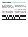
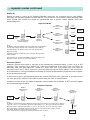
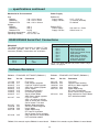
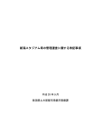
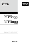
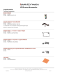
RDT
RM96xx
Radio Modem Series
User Manual
Table of Contents
Main features and brief description . . . . . . . . . . . . . . . . . . . . . . . . . . . . . . . . . . . . . . . . . . . . . . . . . . . . . 2
Additional Information on Power Supplies/Antennas . . . . . . . . . . . . . . . . . . . . . . . . . . . . . . . . . . . . . . . . 3
Modes of Operation
Primary Modes . . . . . . . . . . . . . . . . . . . . . . . . . . . . . . . . . . . . . . . . . . . . . . . . . . . . . . . . . . . . . . . 4
Repeater Modes . . . . . . . . . . . . . . . . . . . . . . . . . . . . . . . . . . . . . . . . . . . . . . . . . . . . . . . . . . . . . . 5
Hayes Mode . . . . . . . . . . . . . . . . . . . . . . . . . . . . . . . . . . . . . . . . . . . . . . . . . . . . . . . . . . . . . . . . . 7
Serial Control Mode . . . . . . . . . . . . . . . . . . . . . . . . . . . . . . . . . . . . . . . . . . . . . . . . . . . . . . . . . . 10
User Control & Configuration
User Controls . . . . . . . . . . . . . . . . . . . . . . . . . . . . . . . . . . . . . . . . . . . . . . . . . . . . . . . . . . . . . . . 13
Table of User Settings . . . . . . . . . . . . . . . . . . . . . . . . . . . . . . . . . . . . . . . . . . . . . . . . . . . . . . . . . 14
Explanation of Features . . . . . . . . . . . . . . . . . . . . . . . . . . . . . . . . . . . . . . . . . . . . . . . . . . . . . . . 15
Timing Diagrams . . . . . . . . . . . . . . . . . . . . . . . . . . . . . . . . . . . . . . . . . . . . . . . . . . . . . . . . . . . . . . . . . .
Specifications . . . . . . . . . . . . . . . . . . . . . . . . . . . . . . . . . . . . . . . . . . . . . . . . . . . . . . . . . . . . . . . . . . . .
Serial Port Connections . . . . . . . . . . . . . . . . . . . . . . . . . . . . . . . . . . . . . . . . . . . . . . . . . . . . . . . . . . . .
Softward Release Information . . . . . . . . . . . . . . . . . . . . . . . . . . . . . . . . . . . . . . . . . . . . . . . . . . . . . . . .
RDT does not assume any responsibility for the use of the products described. No product patents are implied
and RDT reserves the right to change the said products without notice at any time.
1
16
17
18
18
RM96xx
Radio Modem Series
User Manual
Features
●
UHF FM Synthesised Radio Transceiver
●
Transparent serial data transmission
●
●
●
User selectable RF channel, Address
and Tx power level
RS-232 & RS-485 Serial Data Interfaces
●
LED indicators for radio functions, signal
strength and serial line status
6 modes of operation including
Asynchronous, Modem and Repeater
●
Forward Error Correction (FEC)
●
Automatic Repeat Request (ARQ)
Brief Description
The RM96xx Series of Radio Modems are a range of UHF multi-channel transceivers, incorporating a GMSK
baseband modem and RS232/RS485 serial data interfaces.
As with all RDT Radio Modem products, the RM96xx provides fully transparent operation regardless of the
serial data protocol. Over-air speeds up to 16Kbps are achieveable and serial data can be input at various baud
rates up to 19,200bps.
Access to all user configurable parameters is possible using the on-board switches and operational status is
easily monitored using the standard LED indicators.
Models currently available include the RM96xx Modem Card for OEM customers, the RM96xxB Aluminium
housed model and the RM96xxE & EX, IP67 housed units with integral power supplies.
A brief summary of features includes addressing capability, user selectable RF power level and frequency of
operation, built-in repeater facility, Forward Error Correction (FEC), Automatic Repeat Request (ARQ),
MODBUS compatibility (ASCII & RTU) and Hayes Compatible mode.
The RM96xx utilises RDT’s unique multi-channel UHF transceiver which is available as a separate module to
OEM customers wishing to take advantage of the superior design, built quality and performance for which our
products have a world-wide reputation.
Applications include Alarm Systems, Data Acquisition, Remote Metering, Remote Control Systems,
Warehousing and Despatch, SCADA, Security Systems, Video Surveillance Systems, Telemetry, Traffic
Information and Control Systems etc.
The RM96xx products carry the CE mark and meet various UK, European and world-wide radio approval
specifications including ETS 300 113, ETS 300 220 AND MPT1329. Details are available upon request.
2
Additional Information
Power Supply
The RM96xx board requires a 12V d.c. power supply
which should be well filtered and regulated. Onboard voltage regulator circuits will maintain a
constant supply of voltage to the radio and logic
circuits, however, excessive noise, fluctuations and
interference on the d.c. supply may cause loss of
data.
Yellow LEDs indicate minimum acceptable signal,
green LEDs indicate excellent signal strengh.
Coaxial feeder cable is available in many forms, 50
ohm impedance cable with low loss should always
be used, note that 3dB of feeder loss will reduce
radiated power by half. In some applications where
maximum range is required, directional antennae
with gain can compensate for feeder loss provided
that the maximum radiated power limit is not
exceeded.
Antenna Selection
The antenna should be designed for use at the
operating frequency in the 406-470MHz UHF
frequency band. The radio range achieved will be
dictated by the land topography between the nodes.
Ranges quoted below are for guidance only,
distances vary according to terrain and obstructions.
In many situations increasing atenna height can
greatly improve signal strength, and the RSSI test
mode can be used for signal strength indicated.
Antenna Type
Range
When low loss RG213/U or UR67 coaxial cables are
employed N-type RF connectors should be fitted in
conjunction with one of the Antenna Bulkhead Cable
Kits to convert from the SMA of BNC socket on the
radio module to N-type RF connectors on the
coaxial cable.
Coverage
Gain
Mounting
Applications
/2-Wave Whip
1 km
Omnidirectional
-3dB
Enclosure Mounted
Short range general use
End-fed Dipole
10 km
Omnidirectional
0dB
Pole Mounted
Medium range general use
8 Element Yagi
20 km
Directional (40°)
10dB
Pole Mounted
Long range, directional
1
Antenna Types
3
Primary Modes of Operation
Asynchronous Mode
In Asynchronous Mode data arrives through either the RS-232 or RS-485 serial port and is placed in the data
buffer. As soon as data is detected in the buffer, the transceiver is switched to transmit mode. Once switched
to transmit there will be a short delay (10mS), while the synthesiser locks and the transmitter reaches operating
power. The data buffer is then inspected to determine the number of bytes available for transmission in this
data packet. A small amount of header information (used internally by the receiving RM96xx) and the data
bytes are then transmitted along with a 16 bit CRC. After this packet has completed transmission the data buffer
is inspected to see if more data has arrived. If more data is available then the transmission process is
repeated. When no more data is available the transceiver is switched to receive mode.
When an RM96xx header block containing the appropriate modem address, size of data packet and valid
CRC is received then the number of bytes specified in the header block will be read into the data buffer and
then output to the RS-232 or RS-485 serial port.
Point to point, multidrop and repeater configurations are feasible in this mode.
Synchronous Mode
In Synchronous Mode timing constraints are imposed on the serial data. This mode is designed to be used
in systems such as RTU MODBUS where the end of a message is determined by a gap in the serial data
stream of 3.5 characters or more.
Data arrives through either the RS-232 or RS-485 serial port and is placed in the data buffer until a gap of
31/2 characters is detected in the serial byte stream. At this point, no more serial data can be accepted until
the stored data has been transmitted. The transceiver is then switched to transmit and the contents of the
data buffer with a header block are sent as a single data packet. The transceiver is then switched to receive
mode.
Following reception of a valid header block for synchronous mode, the data packet received is placed into
the data buffer. When all the data is in the buffer it is output synchronously to the serial port to ensure no gaps
appear in the serial data stream.
Point to point and multidrop configurations are feasible in Synchronous Mode.
Modem Mode
In Modem Mode the transceiver is controlled with the CTS/RTS control line. To transmit, the CTS input must
be taken high. When the synthesiser has locked and the transmitter reached operating power the modem will
set RTS output high. This signals the user that the RM96xx is now available to accept serial data. Once
RTS is raised, the RM96xx will operate in accordance with Asynchronous mode with the exception that the
transceiver will stay in transmit until the user lowers CTS.
Note: The diagrams of pages 16 & 17 provide timing information on each of the above modes.
4
Repeater Modes
From time to time it is necessary to include a repeater in a system for the following reasons:•
To extend range
•
To circumvent obstacles
•
Achieving a radio link where circumstances dicate the use of less efficient antennas
A system using a repeater is inherently more complex than one without and it is recommended that first time
users may wish to discuss the details of system operation with their modem supplier.
Repeater Modes
The RM96xx series modems have three repeater modes, Standard, Repeat All and Automatic Repeat.
These are selected by the normal programming method with the rotary switch in position 3 and using DIL
switches 4, 5, 6 and 7.
Standard Repeater
In the Standard Repeater mode all RM96xx units within the system must be set to the same address. The base
unit is configured as a standard unit, the repeater is set to 'Standard Repeater' and the remote units must be
set to 'Repeater Remote' (see page 14 for switch settings).
The base unit transmits data with a standard header block. To avoid unneccesary interference and the
possibility of the remote units interpreting the base station transmissions, the remote units will not accept
messages with the standard header block.
When the repeater receives data from the base unit, the header block is changed prior to
re-transmission so that the remote units will recognise the transmission.
In the same manner, a remote unit can only transmit data back to the base station via the repeater which
changes the header block to the standard acceptable by the base unit.
Standard Repeater
PC
Serial
I/O
RM96xx
Address 0
RM96xx
Standard Repeater
Address 0
RM96xx
Repeater Remote
Address 0
Serial
I/O
RM96xx
Repeater Remote
Address 0
Serial
I/O
RM96xx
Repeater Remote
Address 0
Serial
I/O
RM96xx
Repeater Remote
Address 0
Serial
I/O
Notes
An RM96xx in Standard Repeater Mode will receive data from normal RM96xx units
or from Repeater Remote Units providing they are set to the same address.
A normal RM96xx unit will not receive messages directly from a Repeater Remote.
A Repeater Remote unit will not receive messages directly from a normal RM96xx.
5
User
Equipment
User
Equipment
User
Equipment
User
Equipment
... repeater modes continued
Repeat All
Repeat All mode is similar to the Standard Repeater mode with the exception that all valid RM96xx
messages are repeated regardless of their address. This permits the use of a base station operating under
Serial Control and enables the master to communicate with a specific remote modem rather than
broadcasting to all.
Repeat All Mode
RM96xx
Repeater Remote
Address 1
Serial
I/O
User
Equipment
RM96xx
Repeater Remote
Address 2
PC
Serial
I/O
RM96xx
Serial Control Mode
(Variable Address)
Serial
I/O
User
Equipment
RM96xx
Repeat All
RM96xx
Repeater Remote
Address 3
Serial
I/O
User
Equipment
Notes
An RM96xx in Repeat All Mode will receive data from normal RM96xx
units or from Repeater Remote Units regardless of their address.
RM96xx
Repeater Remote
Address 4
A normal RM96xx unit will not receive messages directly from a
Repeater Remote.
Serial
I/O
User
Equipment
A Repeater Remote unit will not receive messages directly from a
normal RM96xx.
Date sent from the Serial Control RM96xx will only be output at the
Repeater Remote which is set to the same address.
Automatic Repeat
Automatic Repeat mode allows a message to be automatically transmitted along a ‘chain’ of up to 255
repeaters. Each repeater has its address set 1 above its predecessor in the chain. Each unit ‘listens’ for
messages from units with addresses 1 below or 1 above their own. (For example unit 6 will listen for
messages from 5 and 7). When it receives a message from the higher of lower address it will re-transmit it
on its own address. Having transmitted it will disable its receiver for approximately 50mS to prevent reception
of the onward transmission.
A received message is repeated and output to the selected serial port at the same time. A message input at
the serial port of any modem in the chain will travel along the chain in both directions.
Customers wishing to use this mode of operation should contact their distributor or RDT technical support
for system planning assistance.
Automatic Repeater
RM96xx
Auto-Repeater
Address 0
PC
Serial
I/O
A
RM96xx
Auto-Repeater
Address 1
RM96xx
Auto-Repeater
Address 2
B
RM96xx
Auto-Repeater
Address 3
C
Notes
An RM96xx in Automatic Repeater Mode will Transmit on its own address and receive on an address 1
higher or 1 lower. i.e. Unit B (above) will transmit with address of ‘1’. Messages from other Automatic
Repeaters will be accepted if their address is ‘0’ or ‘2’. All units must be on the same RF channel.
After transmitting, an Automatic Repeater will be ‘deaf’ for a pre-defined time period:- (16k RF
rate=50mS, 8k RF rate=100mS, 4k RF rate=150mS).
This is to prevent unit A hearing the onward tranamission from unit B etc.
6
D
Serial
I/O
User
Equipment
Hayes Mode Operation
Introduction
When operating in Hayes Mode, the RM96xx Series of Radio Modem products accepts and responds to a
subset of the world industry standard AT command set.
This permits a wide variety of systems primarily intended for PSTN operation to function over a dedicated
radio link without any changes to the system software.
As an intelligent data communications device, the RM96xx analyses and executes commands sent to it as
strings of ASCII characters. Provided that an appropriate communications program is active on the
computer, you may enter AT commands at the keyboard. Otherwise, you may issue commands through a
program in any programming language.The RM96xx returns messages in ASCII string format.
Connection Diagram
RM96xx
9 Way D-Type
DCD
RxD
TxD
CTS
RTS
GND
1
2
3
8
7
5
DCD
RxD
TxD
CTS
RTS
GND
User Equipment
9 or 25 way D-Type
Operational Overview
Three system configurations are possible using the RM96xx series in Hayes mode, these are, Point-toPoint, Polled Network and Random Network.
Point-to-Point
Used in this configuration, a connection can be established which allows bi-directional data transfer
between two points. Either point can initiate the connection process.
Polled Network
In this configuration, the same RF channel is used by all modems in the network. The connection and data
communication process is handled by one master modem which connects to each remote modem in turn,
communicates using bi-directional data transfer, and then 'hangs-up'. This procedure can then be
repeated for all modems within the network.
Random Network
This configuration is similar to the polled Network with one exception; in addition to the master modem
being able to initiate the connection process, any of the remote modems can attempt to connect when the
RF channel is free.
It should be noted that significant delays in overall system performance are possible when using the
Random Network configuration due to the lack of control within the system.
7
... hayes mode continued
System Operation
Each RM96xx has a user configurable address in the range 0-255 which is set via an on-board dil switch.
This address is effectively the telephone number used by the master station or another remote station when
initiating a connection between two units.
As an example, the text string ATDT141 will initiate a connection sequence to the RM96xx with address
141. If no connection can be made the RM96xx will respond with NO CARRIER.
If a successful connection is made, the Carrier Detect LED, D1, illuminates signifying that a current
connection is in progress and the DCD line is raised (pin 1 RS232 connector).
Data is then transferred Asynchronously and is terminated by a standard hangup sequence such as +++
ATH0, which drops the DCD line and turns off LED D1.
A detailed description of Asynchronous data transfer can be found on page 4.
Selecting Hayes Mode
To select Hayes mode, set the rotary switch (SW2) to position 8, set DIL switch position 1 to ON and press
the 'Store' button.
When Hayes mode has been selected, the RM96xx will send and receive data Asynchronously. No other
operating mode can be selected.
In addition, the following functions are disabled when in Hayes mode: Serial Control, All Repeater Modes,
ARQ Modes.
The software has been designed to automatically de-select any of the above modes when the Hayes mode
is selected.
AT Commands Supported
The following AT commands are supported:- ATA, ATD, ATDT, ATDP, +++, ATH, ATH0,
ATSn=m registers supported are;
(defaults in brackets)
S0=x
S2=x
S7=xx
S12=xx
(No Echo)
Auto answer
Esc Code Character
Wait for Carrier
Esc Guard Time
(on)
(+)
(30s)
(1s)
x=0 for off, x=1 for ON
Enter the Decimal ASCII value
Enter Wait for Carrier in seconds
Enter in units of 1/50th Second (i.e 50 = 1 second)
Standard RM96xx Responses
The following responses will be provided by the RM96xx to AT commands;
ERROR, RING, CONNECT, NO CARRIER, BUSY, OK
Notes
i)
ii)
iii)
iv)
v)
vi)
vii)
viii)
ix)
The structure of all AT commands is understood and those not implemented answer OK.
If there is no RS232 activity for 30 secs, the modem 'hangs-up' and drops the CD line.
When dialling (ATDxxx), the recipients address (xxx) MUST contain three digits.
Every Modem in the Hayes network must have a unique address.
A modem in Hayes mode will ignore any data from a modem NOT in Hayes mode.
The RS232 serial port is disabled while waiting for a connection after dialing (see register S7).
To hangup, after guard time send three Esc Code characters, wait for 'OK', send ATH0.
ATA can be sent as a repsonse to 'RING' when not in Auto Answer mode in order to connect.
All commands must be entered in UPPER CASE and terminated with a carriage return.
8
... hayes mode continued
Ring Indicator (RI) operation for the RM9600/9634
The following applies to RM9600 software version 2.5 upwards, and RM9634 software version 2.6 upwards.
Pin 9 of the RS232 connector is the Ring Indicator output when the modem is set to Hayes mode. It’s
operation is as follows:
If the modem is set to non-autoanswer mode (register S0=0), the RI line will be raised (+12V) on reception
of an incoming call request and only be lowered (-12V) if any of the following conditions occur:
1.
The call is answered by the reception of the string ‘ATA<CR>’ into the RS232 port.
(<CR> = carriage return).
2.
The ‘Wait for Connect’ timer at the sending end times out. (In this case the sending end clears the RI
at the receiving end by sending a special header message).
3.
30 seconds have elapsed since the RI line first rose. (This ensures that the RI line is never left in the
incorrect state).
NOTE that if the modem is set to auto-answer mode (register S0=1 which is the default state), the RI Line
does not change state, and remains low (-12V).
9
Serial Control Mode
Introduction
Selecting Serial Control mode permits various Radio Modem parameters to be interrogated and modified
via the serial port instead of using the on-board DIL switches.
In some applications the user equipment takes care of addressing in which case an RM96xx operating in
one of the standard modes can be utilised to provide a straight forward transparent serial data link.
In applications where the user equipment is not addressable, the address of the base station RM96xx will
need to be changed to enable communications with remote units that are set to unique addresses. In
applications such as this, Serial Control provides the solution.
FIG. 1 Example System Configuration
Operational Overview
A typical configuration is detailed in Fig.1 above. Basically, in a polled system with one master
unit and several remote units the system operates as follows;
Each remote unit is a standard RM96xx with a unique address and/or RF channel set via the
on-board DIL switches.
The master unit is set to operate in Serial Control Mode. It receives ASCII text strings from the host in a
simple format which specify or interrogate it's address or RF channel number.
The master unit responds to the host with a reply string confirming the action or containing the value of the
address/RF channel number currently set.
Serial data is transferred until a command is received to change to another address or RF channel.
In this configuration the master station can only listen to one remote station at a time. This is not a problem
when using a polling system because the radio modems communicate with each other in pairs.
Global Addressing
Global addressing may be selected from software versions 2.4 (RM9600) and 2.5 (RM9634) onwards. This
function allows a broadcast message to all stations in systems operating under serial control where
messages are normally directed to a specific selected station. It is activated by sending the serial control
command to select address 255 to the master station or any station that must broadcast to all others on the
system.
10
... serial control mode continued
Configuring the RM96xx
Setting Serial Control Mode
Select Serial Control mode by turning the rotary switch (SW2) to position 3 and switching DIL switch SW1
position '3' to the 'ON' position.
Ensure that all the remaining DIL switches are set to the required positions before pressing the STORE
button (SW3) to activate the settings.
Return the rotary switch to the '0' position when all options are configured.
Operation
Upon power-up the RM96xx will use the current DIL switch settings for Address and RF Channel. If the DIL
switches are changed during operation then this change will overide the last serial command.
The serial commands will only work in RUN mode, with either of the following operational modes selected:Asynchronous Mode with or without ARQ
Synchronous Mode with or without ARQ
Set or Interrogate commands will only be accepted if the RM96xx has no data to transmit and no data to
output on the serial port, otherwise they will be ignored and no response returned on the serial port. If there
is no response to a command, programming has not been successful.
Note that an RM96xx can only be successfully reprogrammed when it has completed it's present data
transfer.
The maximum time taken to program an Address is 2mS.
The maximum time taken to program a new RF channel is 15mS.
The responses to Address and Channel commands will occur within the times indicated above (assuming
the commands were successful).
If the requested RF channel exceeds the maximum allowed (as defined by the radio), then the RM96xx
defaults to the highest permissable RF channel.
Any input string that does not meet the command string format or specifies an address that is out of range
will be treated as normal ASCII text and transmitted.
Guard Time
In some instances, the user's data may be the same as a valid command string which will cause problems
with the system operation.
With a <GUARD TIME> selected, any command string must be preceded by a period of inactivity on the
serial interface which is the same as or longer than the <GUARD TIME> selected. Each command is
preceded by a <GUARD TIME>, the length of which is user selectable.
Users not wishing to use the <GUARD TIME> facility must select 'No Guard Time' from the options
available.
ROTARY SWITCH = 7
SWITCH SW1
1
2
Description
SPARE
SPARE
Options
4
3
Serial Control
Guard Time
OFF
OFF
5
6
7
8
ARQ
Retries
Global
Address
SPARE
SPARE
OFF = No Guard Time
ON = 200 mS
OFF = 20
OFF
ON
OFF = 500 mS
ON = Infinite
ON
ON
ON = 1 Second
Bold items denote factory defaults.
11
... serial control mode continued
Command Format
Serial Control mode allows the user to set or enquire about the value of an Address or RF Channel number.
The command format for each of the functions is as follows:
Set Address
Send Text String
<GUARD TIME>"A000
<GUARD TIME>"A001
<GUARD TIME>"A002
<GUARD TIME>"A003
"
RM9600 Reply String
"A:000<CR>
"A:001<CR>
"A:002<CR>
"A:003<CR>
"
<GUARD TIME>"A255
"
Function
Sets Address
Sets Address
Sets Address
Sets Address
0
1
2
3
"
"A:255<CR>
Sets Address 255
Note <CR> signifies a carriage return code
Interrogate Address
Send Text String
<GUARD TIME>"A???
RM9600 Reply String
"A:xxx<CR>
Function
Returns current address in xxx
RM9600 Reply String
"C:000<CR>
"C:001<CR>
"C:002<CR>
"C:003<CR>
Function
Sets Channel
Sets Channel
Sets Channel
Sets Channel
Set RF Channel No.
Send Text String
<GUARD TIME>"C000
<GUARD TIME>"C001
<GUARD TIME>"C002
<GUARD TIME>"C003
"
0
1
2
3
"
"
Up to maximum number of channels as specified in the EEROM
Interrogate Channel No.
Send Text String
<GUARD TIME>"C???
Notes
1.
RM9600 Reply String
"C:xxx<CR>
Function
Returns current channel no - xxx
The command format is case sensitive - all commands must be in UPPER CASE.
2.
Any character string not compliant with the above formats will not be recognised and will be
transmitted as normal data.
3.
Detection of the " character will cause the modem to re-sync it's 4 byte capture to the first
byte of the string. This enables the modem to respond correctly following a character loss.
4.
Each command is preceeded by a <GUARD TIME>, the length of which is selectable with the
rotary and DIL switches.
12
User Controls
Factory Settings
User Configuration
The RM96xx is shipped from the factory pre-programmed to operate with the following settings:-
Settings are altered by following 3 simple steps:-
Serial Port
Mode
Listen Before Tx
Serial Port
Baud Rate
Parity
Data Bits
Stop Bits
Async, FEC On
ON
RS232
9600
None
8
1
RF Parameters
RF Channel
Power Level
Address
RF Data Rate
1
500mW
0
16K
1.
Adjust Rotary switch (SW2) for desired
function (see table 1)
2.
Select required parameters using DIL
switch (SW1)
3.
Press 'STORE' button (SW3)
The above steps may be repeated for each Rotary
Switch function indicated in the table on page 14.
(refer to notes for exceptions to this rule)
To ease configuration, LED indicators D10-D17
display the current stored DIL switch settings for
each rotary switch function, excluding functions '0'
and '1'.
99 mm
4 x Mounting holes are M3 (3mm)
LED FUNCTIONS (Run Mode)
D10 Carrier Detect
D11 Buffer Full
D12 Receive Serial Data
D13 Transmit Serial Data
D14 RF Receive
D15 RF Transmit
D16 Supply Voltage
D17 Supply Voltage
D10
D17
ON
Radio Data Technology LTD 1996 RM9600/1
SW1
Type IRDN031/0
Frequency Range
ERP
406 to 470 MHz
500 mW max.
C
130mm
UHF Synthesised
FM Transceiver
Made in England
Radio Data Technology Ltd
D1
RS232
1
2
3
RS485
109 mm
FIG. 2 RM96xx Radio Modem Board Layout
13
D8
DC
Supply
+12V
GND
LED FUNCTIONS (All Modes)
Red=LOW (< -5v)
Green=HIGH (> +5v)
D1 CTS (input to RM9600)
D2 DSR (input to RM9600)
D3 DCD (output from RM9600)
D4 RxD (input to RM9600)
D5 TxD (output from RM9600)
D6 DTR (output from RM9600)
D7 Spare (reserved)
D8 RTS (output from RM9600)
120mm
SW3
1 2 3 4 5 6 7 8
SW2
RM96xx User Configurable Settings
ROTARY SWITCH = 0
1
2
RF POWER
OFF
OFF
OFF
ON
ON
OFF
ON
ON
RUN MODE
SWITCH SW1 3
4
50mW
100mW
250mW
500mW
OFF
OFF
etc.
ON
5
6
RF CHANNEL
OFF
OFF
OFF
OFF
etc.
etc.
ON
ON
SWITCH SW1 3
4
5
Receive
Transmit
OFF
OFF
etc.
ON
OFF
OFF
etc.
ON
OFF
OFF
etc.
ON
7
8
OFF
OFF
etc.
ON
OFF
ON
etc.
ON
LOWEST FREQ
HIGHEST FREQ
ROTARY SWITCH = 1
1
2
TEST MODE
OFF
ON
-
TEST
ROTARY SWITCH = 2
ADDRESS
OFF
OFF
etc.
ON
1
2
3
OFF
OFF
etc.
ON
OFF
OFF
etc.
ON
OFF
OFF
etc.
ON
6
7
RF CHANNEL
OFF
OFF
OFF
OFF
etc.
etc.
ON
ON
4
5
6
UNIT ADDRESS
OFF
OFF
OFF
OFF
OFF
OFF
etc.
etc.
etc.
ON
ON
ON
7
8
OFF
OFF
etc.
ON
OFF
ON
etc.
ON
8
OFF
ON
etc.
ON
LOWEST FREQ
HIGHEST FREQ
Note: Address 255 is reserved for
broadcasting a message in Serial Control
mode. Please refer to ‘Global Addressing’
section of Serial Control on page 10.
ADDRESS '0'
ADDRESS '255'
ROTARY SWITCH = 3
1
2
PRIMARY MODE
OF OPERATION
OFF
OFF ASYNC
OFF
ON SYNC
ON
OFF MODEM
ON
ON N/U
OPERATING MODE
3
4
5
6
7
SERIAL REPEATER REPEAT ALL AUTO REPEAT REPEATER
CONTROL ON/OFF
ON/OFF
ON/OFF
REMOTE
OFF-X-X
= REPEATER OFF
OFF
OFF
ON-OFF-OFF = STANDARD REPEATER
ON
ON
ON-OFF-ON = AUTOMATIC REPEATER
ON-ON-OFF = REPEAT ALL
8
RS232/
RS485
OFF =
RS232
ON =
RS485
ROTARY SWITCH = 4
1
RF PARAMETERS
2
RF BAUD
RATE
OFF
OFF
OFF
ON
ON
OFF
ON
ON
3
LISTEN
BEFORE Tx
4
FEC
ON/OFF
5
ARQ
ON/OFF
OFF
OFF
OFF
ON
ON
ON
4K
8K
16K
N/U
8
6
7
RTS/CTS
ARQ
DSR/DTR
HANDSHAKE H'SHAKE TIMEOUT
OFF=
OFF
OFF
Std
ON=
ON
ON
Extended
ROTARY SWITCH = 5
1
SERIAL INTERFACE
CONFIGURATION
2
OFF
OFF
OFF
OFF
ON
ON
ON
ON
ROTARY SWITCH
ROTARY SWITCH
ROTARY SWITCH
ROTARY SWITCH
=
=
=
=
4
3
SERIAL PORT
BAUD RATE
6
7
8
F
OFF
OFF
ON
ON
OFF
OFF
ON
ON
OFF
ON
OFF
ON
OFF
ON
OFF
ON
5
6
150
300
600
1200
2400
4800
9600
19200
UPDATE EEROM
SERIAL CONTROL
HAYES MODE
FACTORY SETTINGS
(See
(See
(See
(See
OFF
ON
ON
OFF
OFF
ON
7
8
STOP
BITS
CHARACTER
LENGTH
PARITY
NONE
EVEN
ODD
OFF
OFF
ON
OFF
ON
ON
7 BITS
8 BITS
9 BITS
OFF
ON
1
2
notes page 15)
pages 10-12)
pages 7-9)
notes page 15)
ROTARY SWITCH POSITIONS '9' TO 'E' ARE NOT USED
BOLD ITEMS DENOTE FACTORY DEFAULTS
14
Summary of Features
RF Channel
Binary coded RF Channel number. Refer to the
frequency list supplied with each unit for
corresponding frequency of operation
Automatic Repeat Request (ARQ)
This feature can be enabled with any of the primary
modes of operation with the exception of Modem
Mode. When using ARQ, the primary mode operates
in the same way as described on page 2 but each
transmission is acknowledged by the receiving unit.
If no acknowledgement is received within 500mS or
a repeat request is received, the transmitter sends
the data again up to a maximum of 20 times before
moving to the next block of data.
ARQ can only be used in a point-to-point system or
in a Serial Control system where all remote units
have a different address. Standard Repeater
systems can also use ARQ providing that the ARQ
timeout feature is set to extended
Address
Binary coded unit Address (0-255). Only units with
the same address will communicate.
Test Mode
Receive
LED's D10-D17 act as a received
signal strength indicator in the form of a bar-graph.
Yellow LED's indicate minimum acceptable signal,
green LED's indicate excellent signal strength.
Transmit Unit transmits continuous modulated
carrier.
These features can be used to ascertain the link
quality between two units.
RTS/CTS Handshake
This feature should be turned 'OFF' when the
RM96xx is being used with a standard 3-wire
connection to the user equipment (Tx, Rx, GND).
This type of connection is the most common.
When switched 'ON', the RM96xx requires the
CTS line to be controlled by the user
equipment.
The RTS line will be lowered when there is only
256 bytes of space left within the transmit buffer
and raised once again when the buffer is empty.
Lowering the CTS line causes the RM96xx to buffer
any data received over the RF link. Raising the
CTS line forces the RM96xx to output the serial
data.
Operating Mode
Various operating modes can be selected. Please
refer to the detailed description of each mode on
page 4 before selecting.
Serial Control
This mode of operation permits the user to alter
various RM96xx parameters via the serial port
instead of using the on-board switches. A detailed
description can be found on page 10.
Repeater
Please refer to the detailed description of Repeater
operation on pages 5-6.
DSR/DTR
This feature can be used as a means of switching +/12V over the RF link.
Raising DSR (+12v) on one RM96xx unit will cause
DTR on the receiving unit to also be raised.
Lowering DSR (-12v) will cause DTR on the
receiving unit to be lowered. The effects of
raising/lowering the DSR line are immediate and are
independant of any serial data activity.
RF Data Rate
The RF data rate can be adjusted to improve range/
data integrity for applications that do not require
high data rates. A low RF Data Rate will improve
range a high RF data rate will reduce it.
Listen before Tx
With this feature 'OFF', the RM96xx will transmit
serial data regardless of RF channel activity. If
switched 'ON', the unit will only transmit when the
RF channel activity is below that of the RSSI
threshold. Otherwise data is buffered until the
channel becomes free.
USER CONFIGURATION NOTES
Rotary Switch position 6 (Update EEROM)
In this position it is possible for the contents of the
EEROM within the radio to be modified. This is an
engineering function and should only be performed
with the appropriate software and technical support
from RDT.
FEC (Forward Error Correction)
When selected, this feature will correct small data
errors at the receiving RM96xx without having to
re-transmit the data.
It should be noted that this feature will require an
overhead to operate. Therefore, to achieve
9600bps transparently the RF data rate must be
set to 16k.
Rotary Switch position F (Factory Defaults)
Pressing the STORE button (SW3) with the rotary
switch in this position will cause all current settings to
be returned to the factory defaults listed on page 14.
15
Timing Diagrams
Transmitter
Receiver
Fig. 3 Asynchronous Mode Transmit/Receive Timing Diagram
Transmitter
Receiver
Fig. 4 Asynchronous ARQ Mode Transmit/Receive Timing Diagram
Transmitter
Receiver
Fig. 5 Synchronous Mode Transmit/Receive Timing Diagram
Transmitter
Receiver
Fig. 6 Synchronous ARQ Mode Transmit/Receive Timing Diagram
16
.... timing diagrams continued
Transmitter
Data
RXD
CTS
RTS
TX
Radio
RX
1
Receiver
Header
Block
Data
3
2
1 = Transceiver lock time &
Trans mitter pow er up
= 10 mS max .
2 = Time var ies with quantity of
data still to Tr ansmit.
3 = Transceiv er lock time TX to RX
= 10 mS max .
R TS
C TS
TX
Radio
RX
TXD
Data
Fig. 7 Modem Mode Transmit/Receive Timing Diagram
Specifications – Specific Models
RM9600
General
Frequency Range
RM9634
General
Frequency Range
10MHz band in the range
406 - 470 MHz
Channel Spacing
10, 12.5, 20 or 25kHz
Transmitter
RF Power Output
Adj. Channel Power
Freq. Tolerance
FM Deviation
50 - 500mW (in 4 steps)
-37dBm
± 3ppm
± 3.5kHz
Receiver
RF Sensitivity
- 110dBm for 10-4 BER
Channel Spacing
10MHz band in the range
406 - 470 MHz
12.5, 20 or 25kHz
Transmitter
RF Power Output
50 - 500mW (in 4 steps)
Adj. Channel Power
-37dBm
Freq. Tolerance
± 1kHz
FM Deviation
± 2kHz
Intermod Attenuation
>40dB
Spurious Emissions <-36dBm 0-1 GHz
<-30dBm 1-4 GHz
Receiver
RF Sensitivity
- 110dBm for 10-4 BER
Co-channel Rejection
>-12dB
Adj. Channel Selectivity
>60dB
Spurious Response Rejection
>70dB
Intermod Response Rejection
>70dB
Blocking >84dB for any signal >50kHz from
the tune frequency
Intermodulation
-70dB
Adj. Channel Rejection -70dB
Spurious Emissions
<-57 dBm
<-47dBm
0-1 GHz
1-4 GHz
Specifications – All Models
RSSI Threshold Level
Max. Bit Rate
Modulation
Interface Baud Rate
Parity
Data Buffer
Stop Bits
Data Bits
-105dBm at 16K
-110dBm at 8K/4K
16kbps (25KHz)
8kbps (10/12.5/20KHz)
GMSK
17
150-19.2 Kbaud, adjustable
Odd, Even or None
4 Kbytes Tx, 2 Kbytes Rx
1 or 2
7, 8 or 9
.... specifications continued
Mechanical & Environmental
Power Supply
Size
RM96xx
RM96xxB
RM96xxE/EX
Weight
RM96xx
RM96xxB
RM96xxE/EX
Operating temperature
Operating humidity
RM96xx/B
Power Supply
Supply Current
130 x 109 x 32mm
142 x 150 x 47mm
280 x 190 x 130mm
RM96xxE/EX
Power Supply
Supply Current
400 g
900 g
3.6 kg
-25 to +60°C
20% to 75% RH
10.5 - 15.5V d.c.
Tx 550mA (500mW)
Rx 260mA
220-260V a.c. 50Hz
250mA max a.c.
RS232/RS485 Serial Port Connections
RS232 9-Way 'D'
Pin 1
Pin 2
Pin 3
Pin 4
Pin 5
Pin 6
Pin 7
Pin 8
Pin 9
RS232/485
The RM96xx has two serial ports, a 9-Way 'D' Type
connector (RS232) and a two part Phoenix
connector (RS485). Connections are as follows:RS485 2-Part
Pin 1
Pin 2
Pin 3
Description
'B'
'A'
'GND'
Description
DCD Data Carrier Detect
RxD Receive Data
TxD Transmit Data
DTR Data Terminal Ready
GND Ground
DSR Data Set Ready
RTS Request To Send
CTS Clear To Send
Rx Buffer Indicator
Pin 9 is the Ring Indicator (RI) when used in Hayes
Mode, see page 9.
Software Revisions
RM9600 - STANDARD SOFTWARE (RM9600-1)
RM9634 - STANDARD SOFTWARE (RM9634-1)
Date
Ver. No
Comments
Date
Ver. No
Comments
11/11/96
26/11/96
26/03/97
02/04/97
03/06/97
10/06/97
15/09/97
22/09/97
V1.0
V1.1
V1.2
V1.3
V1.4
V1.5
V1.6
V1.7
20/11/97
03/06/98
19/06/98
10/03/99
29/07/99
V2.1
V2.2
V2.3
V2.4
V2.5
05/10/99
V2.6
First Issue
Optimise data handling
485 Sync. Mode upgrade
Hayes Mode
Global Addressing
RF Data RX Indication
Serial Control Parity upgrade
Ring Indicator for Hayes Mode
DCD Indication added
04/11/97
V2.0
20/11/97
19/06/98
10/04/99
29/07/99
V2.1
V2.2
V2.3
V2.4
05/10/99
V2.5
First Issue
Data Integrity upgrade
C23/C24 channel upgrade
ARQ Sync. Mode upgrade
20kHz Option
Repeater functionality
Rx interrupt upgrade
Serial Control Mode
ARQ Synch. Mode upgrade
FEC OFF option
ARQ - 20 retries or infinite
Auto RF baud rate selection
Serial Control 7 bit data
Modem Mode operation
485 Sync. Mode Upgrade
Hayes Mode
Global Addressing
RF Data RX Indication
Serial Control Parity upgrade
Ring Indicator for Hayes Mode
DCD Indication added
RM9600 V2.3 onwards requires RM9600-2 control board
RM9634 V2.4 onwards requires RM9600-2 control board
18
Notes
19
Notes
20
Radio Data Technology Limited
10-11 Taber Place Crittall Road Witham Essex CM8 3YP England
Telephone (01376) 501255 Telefax (01376) 501312
Internet: http://www.radiodata.co.uk email: [email protected]
RDT
A member of the CML Microsystems Plc group
© 1999