1
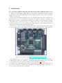
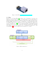
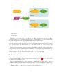
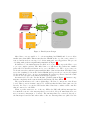
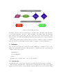
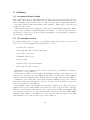
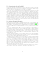
Final report in EDA385
Design of Embedded Systems: Advanced Course
VPN on Nexys2
Dan Kvelstad
Michael Gissing
Leo Bärring
[email protected]
[email protected]
[email protected]
November 29, 2011
Mentor: Flavius Gruian ([email protected])
Abstract
This report summarizes the VPN on Nexys project undertaken for the course
EDA235 at Lunds University during the fall of 2011. The task was to design and
implemented an IPsec compatible endpoint for use in a VPN. This was accomplished
by constructing an embedded system via the FPGA based Nexys2. One of the major
points of the construction was to implement parts of it in Hardware (VHDL) in order
to increase throughput. This goal was ultimately abandoned due to the sheer size
of the undertaking. The system is operational via software but is really slow as a
ping through the VPN has a round-trip-time of almost 300ms.
1
Contents
1. Introduction
1.1. IPsec . . . . . . . . . . . . . . . . . . . . . . . . . . . . . . . . . . . . . . .
1.2. Initial Idea . . . . . . . . . . . . . . . . . . . . . . . . . . . . . . . . . . .
3
4
5
2. Hardware
6
3. Software
3.1. Initialization . . . . . . . . . . . . . . . . . . . . . . . . . . . . . . . . . .
3.2. Handling . . . . . . . . . . . . . . . . . . . . . . . . . . . . . . . . . . . . .
3.3. IPsec . . . . . . . . . . . . . . . . . . . . . . . . . . . . . . . . . . . . . . .
8
8
9
9
4. Installation and User Manual
10
5. Problems
5.1. Incremental System Design . . . . .
5.2. SPI controller and bus . . . . . . . .
5.3. Communication with the PmodNICs
5.4. Hardware Encryption/Decryption . .
.
.
.
.
.
.
.
.
.
.
.
.
.
.
.
.
.
.
.
.
.
.
.
.
.
.
.
.
.
.
.
.
.
.
.
.
.
.
.
.
.
.
.
.
.
.
.
.
.
.
.
.
.
.
.
.
.
.
.
.
.
.
.
.
.
.
.
.
.
.
.
.
.
.
.
.
.
.
.
.
.
.
.
.
11
11
11
12
12
6. Lessons Learnt
13
Bibliography
14
A. Packets Flow
15
B. Contributions
16
2
1. Introduction
Two computers communicating via a insecure network runs a significant risk of eavesdropping or manipulation. To alleviate the situation a security system such as IPsec can
be employed by the clients. But relying on each client to implement security is a suboptimal since it most likely will introduce throughput loss and unacceptable complexity
addition for end user.
Moving the security implementations to the gateway will reduce the complexity for
the users since they can communicate as usual. Users know nothing of security other
than that it is secure communication. Moving the security to the gateway also has the
benefit that only one system needs to be configured in order to secure a whole network.
A single special purpose secure gateway also enables the use of specialized hardware in
this gateway, theoretically improving throughput.
The purpose of this project is to implement a IPsec endpoint with this functionality.
For prototyping purposes the FPGA based Nexys2 from Digilent Incorporated was used.
c
Figure 1: Nexys2 Board http://www.digilentinc.com/
The Nexys2 board does not support networking out-of-the-box but there are add-on
circuits, Pmods, that can be utilized to add functionality such as this to the board. This
project make heavy use of the PmodNIC presented in Figure 2 beneath.
As this project will implement routing functionality it uses two PmodNIC devices.
These devices consists of a Microchip enc28j60 circuit with supporting crystal and connectors for the Pmod interface and RJ45.
3
c
Figure 2: PmodNIC http://www.digilentinc.com/
1.1. IPsec
Internet Protocol Security (IPsec)[3] is a suite of protocols designed to secure the communication in IP networks. The three most important protocols in this family are
Authentication Header (AH), Encapsulating Security Payload (ESP) and Internet Key
Exchange (IKE). The first two are used to actually improve security during packet transport while the later is used to distribute the needed cryptographic keys. This project
focused on the ESP protocol[2] since it provides data integrity, confidentiality as well as
authenticity. There are two ways of doing VPN: tunneling and transporting. Tunneling
is the simpler of the two and was therefore the one implemented in this project. The
following Figure 3 shows how an ESP packet in tunnel mode looks like.
Figure 3: ESP in tunnel mode
4
There are several cryptographic algorithms specified for use with IPsec. RFC 4835[5]
is the latest version of the specification. AES-CBC with 128-bit keys (RFC 3602[1])
was chosen as the encryption algorithm and HMAC-SHA1-96 (RFC 2404[4]) as the
authentication algorithm.
The set of algorithms and keys used for an IPsec connection is called Security Association (SA). Each direction of data-flow requires one SA, so at least two for a bi-directional
connection.
Figure 4 gives an overview of how our Nexys board is placed in its environment.
Figure 4: Big Picture of a VPN
1.2. Initial Idea
There is an existing market-space for VPN solutions and the system developed in this
course must be compatible with the existing solutions. It is, however, unreasonable to
implement the complete IPsec standard during the allotted time so considerable simplifications were made. It is intuitively understood that encryption and decryption is
two time consuming operations and would benefit greatly of a hardware implementation.
Figure 5 shows the initial solution idea.
The original idea was that a Microblaze core will receive a packet that is either encrypted or plain. Depending on which it is the Microblaze copies it into one of the two
shared memories. These are are partitioned into 3 sections:
• Control by acting as a Mailbox
5
Figure 5: Initial System
• Inbound
• Outbound
The IPsec core’s purpose is to accelerate the AES calculation as well as the SHA1
calculation. The needed padding and data preprocessing shall be done in software while
the round functions of the algorithms are implemented in hardware.
When the IPsec cores remark that the control part tells it to do its processing it will
read the packet from the inbound part and do its transformation and put the result in
the outbound part. The Microblaze core could then append the correct headers and
send the packet.
During development the design went through multiple revisions and the final system
design varied from the original sign in a multitude of ways. The most significant being
that we underestimated the complexity of implementing the IPsec cores. Also, the
implementation of network interfaces turned out to be far from trivial.
2. Hardware
The system design quickly became an iterative process as modifications to the initial
design was implemented, this is closer inspected under Section 5 and we only present
the final system in this section.
The program quickly grew to the magnitude of 30KB and it is impossible to fit it in
a BRAM. This is a known limitation and Digilent provides a 16MB micron memory for
these scenarios. The Micron memory is considerably slower than the BRAMs and relies
on BRAM caches to counteract speed-loss associated with its use.
6
Figure 6: Final System Design
Microblaze cores are unable to boot from anything but BRAM and does not allow
smaller sizes than 8KB. This means that the BRAM in the top left corner cannot be
removed and is used as a storage for both incoming and outgoing packets. The process
of dealing with packets is significantly simplified in Figure 6.
In difference to the initial system, the final one does not really expect the IPsec cores
to process complete packets. The Microblaze core will divide the packets into smaller
parts called blocks and send them one by one to the IPsec core. The core processes one
block and saves the result in registers until the Microblaze fetches them. The Microblaze
stores the resulting blocks in the Packet BRAM and repeat the process for all original
blocks until all are done. A new encapsulating IP packet is generated and the result
blocks are used as payload in this new unencrypted packet.
As mentioned before the ”Packet In/Out” parallelogram in Figure 7 abstracts a significant complexity in the system, namely interfacing the PmodNICs.
The network interfaces are connect physically to the Pmod connections of the Nexys
board. These ports are in turn connected to a SPI bus that the Microblaze cannot access
directly. In order to access the SPI bus the Microblaze has to utilize a SPI controller
that is connected to the PLB.
When a packet arrives at one of the two NICs, the NIC will pull its interrupt line
low until the reason for the interrupt has been resolved. Keep in mind that there are
more reasons for interrupts to be made. The interrupt lines are connected directly to
the Interrupt Controller and when either of the two interrupt lines are pulled low the
7
Figure 7: Networking in Nexys
interrupt controller generates an interrupt to the Microblaze. The Microblaze then have
to access the interrupt controller to find out which of the NICs caused the interrupt
and extract packets via the SPI controller. Once the reason for the interrupt on the
NIC is resolved the NIC will pull its interrupt line high again and go back to standard
operation.
A incoming packet will most likely generate an answer. The flow of these are simpler
since they involve no interrupts but they still need transfer over the SPI interface.
3. Software
The software grew quite large and is more than 30KB after compilation. It does not
utilize an operating system and no threads but it does make heavy use of interrupts. It
consists of three major parts:
• Initialization
• Packet Handling
• IPsec
It makes sense to handle these ones one after another.
3.1. Initialization
A significant part of the Software is all about setting up the IPs provided by Xilinx.
All of the supporting hardware on the Nexys board is implemented. The seven segment
display is used as a heartbeat and switches activates different test cases, such as testing
8
interrupts via a button press. Once it was all up and running it was superseded by the
serial port and serves little purpose in the final system, save for the heartbeat indicator
which alerted us if the software would not return to the main loop at some point.
Next to be configured during the startup routine is the SPI controller. There are
settings about if the clock signal should be kept high or low when resting and if data
should be sampled on rising or falling clock edge etc.
Once the SPI controller has been setup the configuration of the enc28j60-based PmodNICs can begin. The initialization consist of partitioning the internal memory buffer
of the enc28j60 into receive and transmit buffers, enabling interrupts, setting multiple
physical constraints on the communication (full duplex, minimum pause time between
packets) as well as more cosmetic settings such as the significance of the status LEDs.
The interrupt handling supports packet received interrupt on both of the PmodNICs
as well as interrupts via the buttons on the physical board.
3.2. Handling
The processing of a packet is given in Section A. The system is capable of dealing with
ARP request and Pings on both interfaces. This is functionality that greatly helped
implementation and bug hunting and development of the system. The greatest benefit
was the ability to verify parts without setting up the supporting environment.
ARP (Address Resolution Protocol) is the standard way to map IP addresses to MAC
addresses. Support of this protocol greatly simplifies the installation since otherwise
clients would have to map the IP to MAC statically. These packets are never tunnelled
seeing as the tunneling happens on the IP level.
Ping is the standard way of testing IP traffic. Both interfaces of the NICs are assigned
static IP addresses and if the ping packet is addressed to the interface it was received
on the system answers the ping. If the ping is not addressed to our system it will be
treated as a normal IP packet.
Normal IP packets are treated differently depending on which interface they arrive
on. If they arrive on the public packets they checked if they contain an ESP payload. If
this is the case our system attempts to extract the tunneled packet and send it out on
the private interface. If the packet arrives on the private interface it will be encrypted
and sent out on the public interface.
3.3. IPsec
The IPsec software implementation is split in two parts. The first part is the one that
is intended to stay in software even with a fully working hardware IPsec core. This
part handles the actual implementation of the standard algorithms within IPsec. It’s
responsible for adding the proper padding, calculating packet lengths and splitting data
into the right block sizes of the algorithms. This portion of the software is identified by
” sw” in the filename.
The part that does the raw calculations mainly uses two open source implementations
for the SHA1 round function as well as the AES in CBC mode. As mentioned before this
9
software part was intended to be replaced by actual hardware. The intention was that
it should be easy to re-use already available IP-cores of algorithms without the need to
adopt them too much for IPsec requirements. The source files related to this part are
denoted by ” hw” in the file names.
To separate those two parts a PC based high-level C model using pthreads was created. One thread emulated the future software part while the other thread emulated the
hardware. This enabled us to specify the shared memory layout as well as determine
the allocation of tasks between hardware and software. The model can be found in
highlevel/ directory.
An example for the diversion into hardware and software is the calculation of the ipad
and opad used in the HMAC algorithm. For efficiency reasons those are not calculated
on every HMAC calculation but just once for each HMAC key. To obtain the needed Intermediate Hash Values (IHVs) the keys and a specified padding have to be hashed. This
is not done in hardware but in software because this calculation would add additional
complexity to the hardware without significant performance improvement.
4. Installation and User Manual
There is a significant workload for getting the system operational. This is mostly due
to the amount of supporting systems that are needed to see the functionality. First and
foremost is the need for another VPN endpoint to connect to, this work group used a
small embedded system running a standard Debian Lenny GNU/Linux to do this. The
VPN endpoint will need to be configured to use static security associations, which is a
bad idea from a security standpoint, but a necessity in order to keep the scope of the
project narrow enough.
Setting up the Nexys is a tad simpler. Start by connecting the PmodNIC to the two
top left ports on the board when its orientated as in Figure 1. The left interface is the
public and the right is the private.
When generating the bitstream from XPS ensure that the bootloop project is marked
as ”initialize to BRAM”. The Microblaze can only boot from BRAM memory and in
the case of the bootloop awaits further instructions. The developer then need to connect
via XMD and upload the compiled VPN project into the Micron memory.
The developer has to set the IP and MAC addresses as well as encryption information
in the source code of the project. Values that needs setting includes the addresses for
the Nexys board and the other gateway. The client connected to the private side of
the gateway also needs to be inserted since the systems does not send ARP requests to
resolve Ethernet addresses. The corresponding data must match the data used when
configuring the other VPN endpoint.
10
5. Problems
5.1. Incremental System Design
The original plan was to first implement a simple but large system using a second
Microblaze. The rationale was that its easier to implement software first and make sure
that everything works and then refine it. The next step was to implement hardware
components with the same functionality as the emulator. This was the work-flow used
in the preceding course.
This methodology is not very efficient. As it turned out just implementing the software
version of the encryption and hashing functions claimed one of the group members for
the duration of the project. In the end there was simply not enough time to implement
the hardware components.
5.2. SPI controller and bus
For such as simple protocol, the ip-core by Xilinx is quite cumbersome to use. For each
and every one of the transfers the following has to be done:
• Activate the controller
• Deactivate the SPI controllers interrupts
• Select the correct slave
• Transmit desired bytes
• Deselect slave
• Activate SPI controller interrupts
• Deactivate the SPI controller
This flow is not documented and it went so far that the possibilities for writing a
custom SPI core was evaluated.
Connecting one NIC to the SPI bus posed minimal resistance, but adding a second
offered more. Since the two PmodNICs should share the same lines, such as MISO,
each line will have multiple drivers. This would theoretically enable the PmodNICs to
communicate at the same time on the same medium, resulting in erroneous condition.
It should not happen practically due to the use of a Slave Select but XPS does not allow
it and renders an error on synthesis.
An ungainly solution was implemented through a custom pcore that read the SS
signals and acted as a mux/demux between the two slave devices and the controller.
This pcore also had the feature that it could control the PmodNICs’ reset signals. This
core was later replaced by a or gate with the inputs connected to the PmodNICs’ MISO
signals and the output to the MISO pin of the controller. The reset pins of the NICs
was hardwired to Vcc and software reset was used instead.
11
5.3. Communication with the PmodNICs
About at the same time as the SPI bus problems occurred there was also the fact that
the NIC circuits would not respond to the commands, even though the command output
had been verified as both existing and correct with a logic analyzer.
The cause of the problems laid in how the enc28j60 interpreted the Slave Select SPI
signal. The enc28j60 makes use of both two-byte and n-byte commands, where the nbyte commands are used for effectively reading and writing to/from the internal buffers
of the NIC. For the NIC to react on the commands it is important that the SS signal is
kept low for the duration of exactly one command. Initially keeping the SS low was tried
for single or multiple byte sequences independently from the command length, under the
assumption that there would be a fixed size buffer on the NIC that the NIC would pull
the data from when SS goes from low to high. The error was eventually found, but
would have been found earlier if not for the fact that the reset pin of the PmodNIC had
been unconnected for the whole time.
5.4. Hardware Encryption/Decryption
Moving data between the AES core and PLB requires the use of a state machine. The
same machine should also implement the CBC operation described in RFC 3602[1]. This
state machine took considerably longer to implement than expected and the time allotted
to it was not sufficient. As a result the hardware cores not operational as the deadline
passed.
If it can be assumed that the AES core works correctly there are still a number of
problems that could cause the error; a few are a faulty state machine, confused endianness
and read/write timing. Considering that the core+CBC+interface implementation at
a handful points during development returned correctly encrypted data for a single
block encryption, it seems that the AES core is functional and the endianness of the
implementation is correct.
On the other hand, the AES core is very sensitive when it comes to the signal timing
and will only hold the valid encrypted data for a single clock cycle. If the state machine
can not account for this the implementation will not work.
Initially the load/done signals to/from both the AES core, and the propagated signals
to/from the PLB interface was monitored on an external logic analyzer and showed the
expected i/o, even though the returned data was wrong. As the core operates on 128
bits at a time it is a bit hard to monitor the data signals, although an effort was made
just before the deadline. Viewing some of the data lines it seems these are not kept
static between the load and the finishing of the encryption process, as a ”feature” of the
AES core, or maybe a bug in the interface state machine causes everything to break. At
that point there was no time left to find out.
Inexperience with chipscope as well as the external logic analyzer being to heavy to
carry around to each lab also contributed to the failure to pinpoint the error.
12
6. Lessons Learnt
• It is important to get the data sheet directly from the manufacturer’s website (or
other primary source) so that there is no doubt that the data sheet version is the
latest.
• When an understanding of how a device is supposed to be used has been acquired
it is important to check the device’s errata document. Especially if the device is
notorious due to the size of the errata.
• Interfacing hardware over a simple protocol will possibly take longer time than
implementing a software only function, even if the software is complex compared
to the hardware interface.
• It’s important to know your support tools. To know all the features and how they
are handled saves time looking for workarounds.
• Although we thought we specified our project well, we encountered gaps several
times. Writing specifications is an iterative process. Every change should be redocumented again.
• Although we thought we specified our project well, we encountered gaps several
times. Writing specifications is an iterative process. Every change should be redocumented again.
• Text-based chats are no proper replacement for face-to-face meetings.
• Pair-programming can
– improve code quality.
– advance mutual understanding of the project.
– compensate (minor) gaps in the specification.
– speed-up code creation.
• Google Docs is not a proper tool for writing reports.
13
References
[1] S. Frankel, R. Glenn, and S. Kelly. The AES-CBC Cipher Algorithm and Its Use
with IPsec. RFC 3602 (Proposed Standard), September 2003.
[2] S. Kent. IP Encapsulating Security Payload (ESP). RFC 4303 (Proposed Standard),
December 2005.
[3] S. Kent and K. Seo. Security Architecture for the Internet Protocol. RFC 4301
(Proposed Standard), December 2005. Updated by RFC 6040.
[4] C. Madson and R. Glenn. The Use of HMAC-SHA-1-96 within ESP and AH. RFC
2404 (Proposed Standard), November 1998.
[5] V. Manral. Cryptographic Algorithm Implementation Requirements for Encapsulating Security Payload (ESP) and Authentication Header (AH). RFC 4835 (Proposed
Standard), April 2007.
14
A. Packets Flow
The following picture shows the flowchart for processing an incoming packet.
Figure 8: Packet Handling Flow
15
B. Contributions
Task
Project Proposal
Examination
Subtask
Report
Presentation
Presentation
Final Report
IPsec
Software
Hardware
IP
Ethernet & SPI interfacing
System Design
16
Contributors
Dan Kvelstad
Michael Gissing
Dan Kvelstad
Michael Gissing
Dan Kvelstad
Leo Bärring
Michael Gissing
Michael Gissing
Leo Bärring
Dan Kvelstad
Leo Bärring
Dan Kvelstad
Leo Bärring
Dan Kvelstad