1
UNISIM
Virtex 5 FXT Simulator Manual
Gilles Mouchard
Contents
1 Introduction
1.1 UNISIM . . . . . . . . . . . . . . . . . . . . . . . . . . . . . . . . . . . . . . . . .
1.2 Virtex 5 FXT Simulator . . . . . . . . . . . . . . . . . . . . . . . . . . . . . . . .
4
4
4
2 Building the simulator
2.1 Requirements . . . . . . . . . . . . . . . . . . . . .
2.2 Installing SystemC 2.2.0 and SystemC TLM 2.0.1 .
2.2.1 Download the source code . . . . . . . . . .
2.2.2 Uncompressing the source code tarballs . .
2.2.3 Patching the source code (recommended for
2.2.4 Configuring SystemC . . . . . . . . . . . . .
2.2.5 Compiling and installing SystemC . . . . .
2.3 Building the UNISIM Virtex 5 FXT simulator . . .
2.3.1 Uncompressing the source code tarball . . .
2.3.2 Configuring the simulator building process .
2.3.3 Compiling the simulator . . . . . . . . . . .
.
.
.
.
.
.
.
.
.
.
.
.
.
.
.
.
.
.
.
.
.
.
.
.
.
.
.
.
.
.
.
.
.
.
.
.
.
.
.
.
.
.
.
.
.
.
.
.
.
.
.
.
.
.
.
.
.
.
.
.
.
.
.
.
.
.
.
.
.
.
.
.
.
.
.
.
.
.
.
.
.
.
.
.
.
.
.
.
.
.
.
.
.
.
.
.
.
.
.
7
7
7
7
7
8
8
8
8
8
8
9
3 Cross-compiling the simulator
3.1 Requirements . . . . . . . . . . . . . . . . . . . . . . . . . . . . . .
3.2 Installing a cross-compiled SystemC 2.2.0 and SystemC TLM 2.0.1
3.2.1 Download the source code . . . . . . . . . . . . . . . . . . .
3.2.2 Uncompressing the source code tarballs . . . . . . . . . . .
3.2.3 Patching the source code (recommended for g++ ≥ 4.1) . .
3.2.4 Configuring SystemC . . . . . . . . . . . . . . . . . . . . . .
3.2.5 Cross-compiling and installing SystemC . . . . . . . . . . .
3.3 Cross-compiling zlib . . . . . . . . . . . . . . . . . . . . . . . . . .
3.4 Cross-compiling libxml2 . . . . . . . . . . . . . . . . . . . . . . . .
3.5 Cross-compiling Boost . . . . . . . . . . . . . . . . . . . . . . . . .
3.6 Cross-compiling the UNISIM Virtex 5 FXT simulator . . . . . . .
3.6.1 Uncompressing the source code tarball . . . . . . . . . . . .
3.6.2 Configuring the simulator building process . . . . . . . . . .
3.6.3 Cross-compiling the simulator . . . . . . . . . . . . . . . . .
.
.
.
.
.
.
.
.
.
.
.
.
.
.
.
.
.
.
.
.
.
.
.
.
.
.
.
.
.
.
.
.
.
.
.
.
.
.
.
.
.
.
.
.
.
.
.
.
.
.
.
.
.
.
.
.
.
.
.
.
.
.
.
.
.
.
.
.
.
.
.
.
.
.
.
.
.
.
.
.
.
.
.
.
.
.
.
.
.
.
.
.
.
.
.
.
.
.
.
.
.
.
.
.
.
.
.
.
.
.
.
.
9
9
9
9
9
10
10
10
10
10
11
11
11
11
11
.
.
.
.
.
.
12
12
12
13
13
13
13
4 Getting started
4.1 Run-time configuration . . . . . . . . . .
4.2 Loading binaries . . . . . . . . . . . . .
4.3 Serial console . . . . . . . . . . . . . . .
4.4 Using the builtin debugger . . . . . . . .
4.5 Using a GNU crosstool chain . . . . . .
4.5.1 Building a GNU crosstool chain .
1
.
.
.
.
.
.
.
.
.
.
.
.
.
.
.
.
.
.
.
.
.
.
.
.
.
.
.
.
.
.
.
.
.
.
.
.
. . .
. . .
. . .
. . .
g++
. . .
. . .
. . .
. . .
. . .
. . .
.
.
.
.
.
.
.
.
.
.
.
.
.
.
.
.
.
.
. . . .
. . . .
. . . .
. . . .
≥ 4.1)
. . . .
. . . .
. . . .
. . . .
. . . .
. . . .
.
.
.
.
.
.
.
.
.
.
.
.
.
.
.
.
.
.
.
.
.
.
.
.
.
.
.
.
.
.
.
.
.
.
.
.
.
.
.
.
.
.
.
.
.
.
.
.
.
.
.
.
.
.
.
.
.
.
.
.
.
.
.
.
.
.
.
.
.
.
.
.
.
.
.
.
.
.
.
.
.
.
.
.
.
.
.
.
.
4.5.2
4.5.3
Using cross-GCC . . . . . . . . . . . . . . . . . . . . . . . . . . . . . . . .
Using cross-GDB . . . . . . . . . . . . . . . . . . . . . . . . . . . . . . . .
16
16
5 Examples of use
5.1 Building the examples . . . . . . . . . . . . . . . . .
5.1.1 Building the basic system level unit tests . .
5.1.2 Building the MiBench version 1 benchmarks .
5.1.3 Building the light weight Linux distribution .
5.2 Basic system level tests . . . . . . . . . . . . . . . .
5.2.1 Echo . . . . . . . . . . . . . . . . . . . . . . .
5.2.2 Poll . . . . . . . . . . . . . . . . . . . . . . .
5.2.3 Gen . . . . . . . . . . . . . . . . . . . . . . .
5.2.4 Cap . . . . . . . . . . . . . . . . . . . . . . .
5.2.5 PWM . . . . . . . . . . . . . . . . . . . . . .
5.2.6 Autoselect . . . . . . . . . . . . . . . . . . . .
5.2.7 CFI query . . . . . . . . . . . . . . . . . . . .
5.2.8 Chip erase . . . . . . . . . . . . . . . . . . . .
5.2.9 Sector erase . . . . . . . . . . . . . . . . . . .
5.2.10 Single word programming . . . . . . . . . . .
5.2.11 Unlock bypass chip erase . . . . . . . . . . .
5.2.12 Unlock bypass sector erase . . . . . . . . . .
5.2.13 Unlock bypass word programming . . . . . .
5.2.14 Write buffer programming . . . . . . . . . . .
5.3 A light weight Linux distribution . . . . . . . . . . .
5.3.1 The boot program . . . . . . . . . . . . . . .
5.3.2 The Linux kernel . . . . . . . . . . . . . . . .
5.3.3 The device Tree . . . . . . . . . . . . . . . .
5.3.4 The initial RAM disk . . . . . . . . . . . . .
5.3.5 Busybox . . . . . . . . . . . . . . . . . . . . .
5.3.6 The MiBench version 1 benchmarks . . . . .
5.3.7 Running the example . . . . . . . . . . . . .
.
.
.
.
.
.
.
.
.
.
.
.
.
.
.
.
.
.
.
.
.
.
.
.
.
.
.
.
.
.
.
.
.
.
.
.
.
.
.
.
.
.
.
.
.
.
.
.
.
.
.
.
.
.
.
.
.
.
.
.
.
.
.
.
.
.
.
.
.
.
.
.
.
.
.
.
.
.
.
.
.
.
.
.
.
.
.
.
.
.
.
.
.
.
.
.
.
.
.
.
.
.
.
.
.
.
.
.
.
.
.
.
.
.
.
.
.
.
.
.
.
.
.
.
.
.
.
.
.
.
.
.
.
.
.
.
.
.
.
.
.
.
.
.
.
.
.
.
.
.
.
.
.
.
.
.
.
.
.
.
.
.
.
.
.
.
.
.
.
.
.
.
.
.
.
.
.
.
.
.
.
.
.
.
.
.
.
.
.
.
.
.
.
.
.
.
.
.
.
.
.
.
.
.
.
.
.
.
.
.
.
.
.
.
.
.
.
.
.
.
.
.
.
.
.
.
.
.
.
.
.
.
.
.
.
.
.
.
.
.
.
.
.
.
.
.
.
.
.
.
.
.
.
.
.
.
.
.
.
.
.
.
.
.
.
.
.
.
.
.
.
.
.
.
.
.
.
.
.
.
.
.
.
.
.
.
.
.
.
.
.
.
.
.
.
.
.
.
.
.
.
.
.
.
.
.
.
.
.
.
.
.
.
.
.
.
.
.
.
.
.
.
.
.
.
.
.
.
.
.
.
.
.
.
.
.
.
.
.
.
.
.
.
.
.
.
.
.
.
.
.
.
.
.
.
.
.
.
.
.
.
.
.
.
.
.
.
.
.
.
.
.
.
.
.
.
.
.
.
.
.
.
.
.
.
.
.
.
.
.
.
.
.
.
.
.
.
.
.
.
.
.
.
.
.
.
.
.
.
.
.
.
.
.
.
.
.
.
.
.
.
.
.
.
.
.
.
.
.
.
.
.
A Simulator technical reference (generated)
A.1 Introduction . . . . . . . . . . . . . . . . . .
A.2 Licensing . . . . . . . . . . . . . . . . . . .
A.3 Simulated configuration . . . . . . . . . . .
A.4 Using the UNISIM Virtex 5 FXT simulator
A.5 Configuration . . . . . . . . . . . . . . . . .
A.6 Statistics . . . . . . . . . . . . . . . . . . .
A.7 Formulas . . . . . . . . . . . . . . . . . . .
.
.
.
.
.
.
.
.
.
.
.
.
.
.
.
.
.
.
.
.
.
.
.
.
.
.
.
.
.
.
.
.
.
.
.
.
.
.
.
.
.
.
.
.
.
.
.
.
.
.
.
.
.
.
.
.
.
.
.
.
.
.
.
.
.
.
.
.
.
.
.
.
.
.
.
.
.
.
.
.
.
.
.
.
.
.
.
.
.
.
.
.
.
.
.
.
.
.
.
.
.
.
.
.
.
37
. 37
. 37
. 37
. 42
. 42
. 106
. 110
.
.
.
.
.
.
.
.
.
.
.
.
.
.
.
.
.
.
.
.
.
.
.
.
.
.
.
.
.
.
.
.
.
.
.
16
16
16
17
17
17
19
19
20
21
22
23
23
24
24
25
25
26
26
27
28
28
28
30
30
33
33
33
List of Figures
1
2
3
4
5
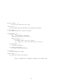
UNISIM Virtex 5 FXT simulator schematic. . . . . . . . . . . . . . . . . . . . . .
crosstool chain build configuration (changes from default only) for Crosstool-NG
1.11.3. . . . . . . . . . . . . . . . . . . . . . . . . . . . . . . . . . . . . . . . . . .
Boot program (boot.S compiled as boot.elf) loaded in BRAM. . . . . . . . . . . .
Linux kernel configuration (changes from default only). . . . . . . . . . . . . . . .
UNISIM Virtex 5 FXT simulator schematic. . . . . . . . . . . . . . . . . . . . . .
2
5
15
29
31
37
List of Tables
1
2
3
4
5
6
Simulator memory mapping. . . . . . . .
Summary of basic system level tests. . .
Files for booting Linux in the simulator.
Linux kernel register parameters. . . . .
Initial RAM disks. . . . . . . . . . . . .
MiBench version 1.0. . . . . . . . . . . .
3
.
.
.
.
.
.
.
.
.
.
.
.
.
.
.
.
.
.
.
.
.
.
.
.
.
.
.
.
.
.
.
.
.
.
.
.
.
.
.
.
.
.
.
.
.
.
.
.
.
.
.
.
.
.
.
.
.
.
.
.
.
.
.
.
.
.
.
.
.
.
.
.
.
.
.
.
.
.
.
.
.
.
.
.
.
.
.
.
.
.
.
.
.
.
.
.
.
.
.
.
.
.
.
.
.
.
.
.
.
.
.
.
.
.
.
.
.
.
.
.
.
.
.
.
.
.
.
.
.
.
.
.
.
.
.
.
.
.
5
18
28
29
32
34
1
Introduction
1.1
UNISIM
UNISIM provides several virtual platforms and a framework to ease the development of new
virtual platforms. A virtual platform is a software tool, often called simulator, that mimics the
behavior of an electronic system so that software can run on it before silicon or FPGA implementation of that electronic system is available. The simulated electronic system can include
lots of microprocessors and devices. Depending on the needed representativeness and simulator
development budget, a simulator can be as simple as an instruction set simulator as well as a full
system simulator. A full system simulator, not only executes the microprocessor instruction set,
like an instruction set simulator, but also simulates buses, I/O devices, sensors, actuators, so
that real application workloads and operating systems can run on them. Most of UNISIM virtual
platforms are full system simulators, which means that they are sufficiently representative of the
real hardware that whole operating systems (e.g. Linux, VxWorks), unmodified software stacks
(e.g. an AUTOSAR software stack), and industrial applications can run on them. The UNISIM
virtual platforms are modular: a simulator is the assembly of properly configured simulation
components (e.g. CPU, RAM, buses). They are written in C/C++ and based on industry
standards, like IEEE1666T M , OSCI SystemCT M and OSCI SystemCT M TLM 2.0.
Some use cases of UNISIM virtual platforms are:
• Development of SystemC IPs (intellectual property) and new virtual platforms: UNISIM
is an open development environment that comprise a SystemC module library, and a set
of services (debugging, program loaders, ). It can be a fundation for the development of
new SystemC IPs and new virtual virtual platforms.
• Hybrid virtual platform: UNISIM/SystemC and an FPGA accelerator can be mixed
to build some hybrid virtual platforms: for instance simulating processor cores within
UNISIM/SystemC, and prototyping specialized IPs/devices within an FPGA accelerator.
Hybridization allows using indifferently both UNISIM/SystemC IPs (on a standard host
machine) and VHDL IPs (on an FPGA accelerator), but also speeding up simulation of
large systems.
• Non-intrusive debugging and testing of software: It means that, unlike on the real hardware, software can be debugged and tested without affecting either its functional and/or
temporal behavior. With such virtual instrumentation, the user can seamlessly stop and
resume execution of software, profile the software, inspect the system status, inject values
on the sensors, modify the state of program variables and microprocessor/device registers,
and then analyze the result without modifying the software.
• Hardware/software integration: software stack can be debugged and tested within a representative hardware environment before the availability of either the FPGA prototypes
or the real hardware. The software stack can be composed of low level software (e.g.
drivers), of a real-time operating system, and of applications generated from high level
models (Papyrus, Matlab Simulink, Statemate Stateflow, )
Several open source virtual platforms for different targets (ARM, PowerPC, Star12X, and
TMS320C3X) and different hosts (Linux, Windows, Mac OS X) are available for download
here. These virtual platforms have been evaluated and used in various industry domains such
as automotive, avionic, military, electrical equipments for medium tension, nuclear safety.
1.2
Virtex 5 FXT Simulator
The UNISIM Virtex 5 FXT is a virtual platform that tries to mimic a Xilinx ML507 development
board that include a Xilinx Virtex 5 FXT (FPGA + PPC440).
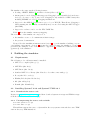
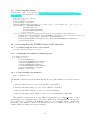
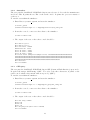
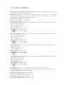
4
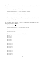
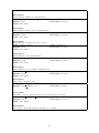
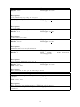
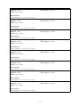
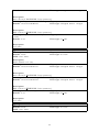
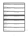
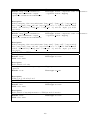
UNISIM Virtex 5 FXT Simulator
PPC440 Embedded Processor BlockSPLB0
ICURD
DCUWR
DCR
Controller
Crossbar
Boot loader
MCI
MCI
RAM
Multi
Format
Loader
DCURD
GDB Debugger
MPLB
NOR Flash
PPC440x5
MMU
TCP/IP
GDB
Server
ITLB
DL1
Operating
System
Applications
ELF
S19
COFF
Raw
S29GL256P
Caches
UTLB
DTLB
Binary Files
SPLB1
BRAM
IL1
HW FPU
(optional APU)
MPLB
External
Input
Interrupt
XPS
GPIO
Telnet/Putty
XPS
Timer
XPS
UART Lite
Telnet
TCP/IP
Trying 127.0.0.1...
Connected to localhost.
Escape character is '^]'.
Booting...
Hello world !
> _
XPS
IntC
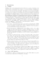
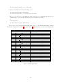
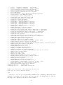
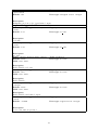
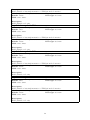
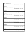
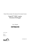
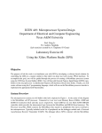
Figure 1: UNISIM Virtex 5 FXT simulator schematic.
Address range
0x00000000-0x0003ffff
0x81400000-0x8140ffff
0x81420000-0x8142ffff
0x81440000-0x8144ffff
0x81460000-0x8146ffff
0x81800000-0x8180ffff
0x83c00000-0x83c0ffff
0x84000000-0x8400ffff
0xfc000000-0xfdffffff
0xfffc0000-0xffffffff
Component name
ram
gpio-leds-8bit
gpio-5-leds-positions
gpio-push-buttons-5bit
gpio-dip-switches-8bit
intc
timer
uart-lite
flash
bram
Hardware device
256 MB RAM
XPS GPIO
XPS GPIO
XPS GPIO
XPS GPIO
XPS IntC
XPS Timer/Counter
XPS UART Lite
S29GL256P
256 KB BRAM
Table 1: Simulator memory mapping.
5
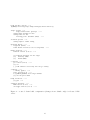
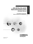
The UNISIM Virtex 5 FXT simulator, which Figure 1 shows the schematic, implements the
following:
• PPC440 Embedded Processor Block (UG200 [9]):
– All the PPC440x5 [4] instruction set of a Xilinx Virtex 5 FXT
– Optional FPU that is similar to Xilinx FPU APU [12]
– PowerPC Book E MMU (shadow ITLB, shadow DTLB, unified TLB)
– Caches (instruction and data)
– Integrated timers (decrementer, fixed interval, watchdog)
– Exception handling mechanisms
– DCR (device control register) bus controller
– Crossbar
– MCI (Memory Controller Interface)
– MPLB (master processor local bus) interface
– SPLB0 and SPLB1 (slave processor local bus) interfaces
• MPLB (master processor local bus) link
• 256 MB RAM on MCI
• 256 KB BRAM on MPLB
• XPS IntC interrupt controller (v2.01a) [10] on MPLB
• XPS Timer/Counter (v1.02a) [11] on MPLB
• Spansion 256 Mbits (32 MB) S29GL256P off-chip flash memory [6] on MPLB
• XPS UART Lite (v1.01a) [8] on MPLB
• Four XPS GPIO modules (v2.00a) [7] on MPLB connected to two LED boards and two
DIP switch/push buttons boards
Several stub modules are currently integrated in the simulator to test the XPS Timer/Counter
module:
• GenerateOut stubs connected on XPS Timer/Counter GenerateOut outputs
• PWM stub connected on XPS Timer/Counter PWM0 output
• CaptureTrigger stubs (optional randomized outputs) connected on XPS Timer/Counter
CaptureTrigger inputs
• SPLB stubs
• DCR stubs
6
The simulator also supports the following features:
• Loading of ELF32, ELF64 [3] and Motorola S19 (S-Record) [2] files
• An integrated console debugger that supports debugging both at assembly level and source
level (e.g. C source code). Source level debugging is only available for ELF binary files
including DWARF v2 or v3 [5] debugging informations
• Support for the GDB [14] serial remote protocol over TCP/IP. That allows debugging a
binary running into the simulator at assembly and/or source level using the GNU debugger
(aka GDB)
• Support for a telnet console over the XPS UART Lite
Table 1 shows the simulator memory mapping.
The 1.0 release of the simulator is composed of:
• the simulator source code: unisim-virtex5fxt-1.0.tar.gz
• the present documentation
Please follow the installation instructions in Section 2 to get the simulator building on your
own building environment. Section 4 presents the basics for using the simulator. Section 5
presents some examples of use of the simulator. Appendix A contains the technical references
(generated) of the simulator.
2
Building the simulator
2.1
Requirements
The following tools or libraries must be installed:
• GNU C++ compiler (aka. g++)
• GNU Flex (aka. flex)
• GNU Bison (aka. bison)
• Standard GNU C++ library (aka. libstdc++-dev that comes with g++)
• Boost (aka. libboost-dev)
• Editline/Libedit (aka. libedit-dev)
• zlib (aka. zlib1g-dev)
• libxml2 (aka. libxml2-dev)
2.2
2.2.1
Installing SystemC 2.2.0 and SystemC TLM 2.0.1
Download the source code
Register at http://www.systemc.org and then download systemc-2.2.0.tgz and TLM-2.0.1.tgz
from the OSCI standards download page.
2.2.2
Uncompressing the source code tarballs
$ tar zxvf systemc-2.2.0.tgz
$ tar zxvf TLM-2.0.1.tgz
This will uncompress the source of SystemC in directory systemc-2.2.0 and the source TLM
2.0.1 in directory TLM-2009-07-15
7
2.2.3
Patching the source code (recommended for g++ ≥ 4.1)
Apply the following patch to SystemC 2.2.0: patch-systemc-2.2.0.gz
$ cd systemc-2.2.0
$ gzip -dc patch-systemc-2.2.0.gz | patch -p1
2.2.4
Configuring SystemC
To configure, compile, and install SystemC in your home directory, do the following at the
command prompt:
$
$
$
$
$
cd systemc-2.2.0
mkdir objdir
cd objdir
mkdir ${HOME}/systemc
../configure --prefix=${HOME}/systemc
Note: if configure needs automake or autoconf, please install these tools, then rebuild SystemC configure script by running these commands before actually running the configure script:
$ cd systemc-2.2.0
$ aclocal
$ automake
2.2.5
Compiling and installing SystemC
To handle threads, SystemC relies on QuickThreads, a fast implementation of user’s threads.
QuickThreads speeds-up threads switching compared to the slower kernel POSIX threads and
thus considerably improves overall simulation performance. To compile SystemC with the builtin QuickThreads (recommended), do the following at the command prompt:
$ make
$ make install
However, if you intend to instrument your simulator (e.g. with valgrind) to debug the
simulator memory leaks, bad memory accesses, pointers, and uninitialized memory reads, you
should use the slower kernel POSIX threads. To compile SystemC with the kernel POSIX
threads, do the following at the command prompt:
$ make pthreads
$ make install
2.3
2.3.1
Building the UNISIM Virtex 5 FXT simulator
Uncompressing the source code tarball
$ tar zxvf unisim-virtex5fxt-1.0.tar.gz
2.3.2
Configuring the simulator building process
$ cd unisim-virtex5fxt-1.0
$ ./configure \
--with-systemc=${HOME}/systemc \
--with-tlm20=${HOME}/TLM-2009-07-15 CXXFLAGS=’-O3 -g3 -Wall’
8
2.3.3
Compiling the simulator
$ make
The simulator binaries are in virtex5fxt/bin subdirectory. The simulators comes in four flavors
in:
• unisim-virtex5fxt-1.0: release simulator without FPU
• unisim-virtex5fxt-wfpu-1.0: release simulator with FPU
• unisim-virtex5fxt-debug-1.0: developement simulator
• unisim-virtex5fxt-wfpu-debug-1.0: developement simulator with FPU
3
Cross-compiling the simulator
This section explains how to build (i.e. cross-compile) the simulator for a host system type
(e.g. Windows) from another build system type (e.g. Linux/i386). The simulator is built on
the build machine whereas it will run on the host machine. In later sub-sections, we consider
cross-compiling the simulator for Windows from a Linux distribution using the mingw32 GCC
cross-compiler. Most Linux distributions provide a mingw32 tool chain as a set of packages.
Once installed the mingw32 tool chain binary file names are prefixed with:
• i586-mingw32msvc- on Ubuntu and Debian Linux distributions
• i686-pc-mingw32- on RedHat, Fedora, and SUSE Linux distributions
• i586-pc-mingw32- on Mandriva and Mageia Linux distributions
The later sub-sections will refer to the mingw32 tool chain of Ubuntu and Debian Linux distributions.
3.1
Requirements
The following tools must be installed on the Linux build system:
• GNU C++ cross-compiler for the host system type (aka. i586-mingw32msvc-g++)
• GNU Flex (aka. flex)
• GNU Bison (aka. bison)
• Standard GNU C++ library for the host machine (aka. libstdc++)
3.2
3.2.1
Installing a cross-compiled SystemC 2.2.0 and SystemC TLM 2.0.1
Download the source code
Register at http://www.systemc.org and then download systemc-2.2.0.tgz and TLM-2.0.1.tgz
from the OSCI standards download page.
3.2.2
Uncompressing the source code tarballs
$ tar zxvf systemc-2.2.0.tgz
$ tar zxvf TLM-2.0.1.tgz
This will uncompress the source of SystemC in directory systemc-2.2.0 and the source TLM
2.0.1 in directory TLM-2009-07-15
9
3.2.3
Patching the source code (recommended for g++ ≥ 4.1)
Apply the following patch to SystemC 2.2.0: patch-systemc-2.2.0.gz
$ cd systemc-2.2.0
$ gzip -dc patch-systemc-2.2.0.gz | patch -p1
3.2.4
Configuring SystemC
To configure, cross-compile, and install SystemC in your home directory, do the following at the
command prompt:
$
$
$
$
$
cd systemc-2.2.0
mkdir objdir
cd objdir
mkdir ${HOME}/systemc-mingw32
../configure --prefix=${HOME}/systemc-mingw32 --host=i586-mingw32msvc
Note: if configure needs automake or autoconf, please install these tools, then rebuild SystemC configure script by running these commands before actually running the configure script:
$ cd systemc-2.2.0
$ aclocal
$ automake
3.2.5
Cross-compiling and installing SystemC
To cross-compile SystemC, do the following at the command prompt:
$ make
$ make install
3.3
Cross-compiling zlib
Download the source code tarball at http://zlib.net/zlib-1.2.5.tar.gz. Uncompress the
source code tarball and cross-compile the library:
$
$
$
$
tar zxvf zlib-1.2.5.tar.gz
cd zlib-1.2.5
mkdir ${HOME}/zlib-mingw32
make -f win32/Makefile.gcc \
PREFIX=i586-mingw32msvc- \
BINARY_PATH=${HOME}/zlib-mingw32/bin \
INCLUDE_PATH=${HOME}/zlib-mingw32/include \
LIBRARY_PATH=${HOME}/zlib-mingw32/lib \
SHARED_MODE=1 install
$ mv ${HOME}/zlib-mingw32/bin/zdll.a ${HOME}/zlib-mingw32/bin/z.dll.a
3.4
Cross-compiling libxml2
Download the source code tarball at ftp://xmlsoft.org/libxml2/libxml2-2.7.8.tar.gz.
Uncompress the source code tarball and cross-compile the library:
$
$
$
$
tar zxvf libxml2-2.7.8.tar.gz
cd libxml2-2.7.8
mkdir ${HOME}/libxml2-mingw32
./configure --host=i586-mingw32msvc \
--without-python --with-zlib=${HOME}/zlib-mingw32 \
CPPFLAGS=’-DLIBXML_STATIC’
$ make
$ make install prefix=${HOME}/libxml2-mingw32
10
3.5
Cross-compiling Boost
Download the source code tarball at http://downloads.sourceforge.net/boost/boost_1_
47_0.tar.bz2. Uncompress the source code tarball and cross-compile the library:
$
$
$
$
$
$
tar jxvf boost_1_47_0.tar.bz2
cd boost_1_47_0
mkdir ${HOME}/boost-mingw32
./bootstrap.sh --without-icu
MINGW32_VERSION=$(i586-mingw32msvc-g++ -v 2>&1 | tail -1 | awk ’{print $3}’ | cut -f 1 -d ’-’)
echo "using gcc : ${MINGW32_VERSION} :
i586-mingw32msvc-g++ :
<rc>i586-mingw32msvc-windres
<archiver>i586-mingw32msvc-ar
;" > user-config.jam
$ ./bjam toolset=gcc target-os=windows variant=release threading=multi threadapi=win32 \
link=shared runtime-link=shared --prefix=${HOME}/boost-mingw32 --user-config=user-config.jam \
--without-mpi --without-python -sNO_BZIP2=1 -sZLIB_BINARY=z.dll \
-sZLIB_INCLUDE=${HOME}/zlib-mingw32/include -sZLIB_LIBPATH=${HOME}/zlib-mingw32/lib \
--layout=tagged install
3.6
3.6.1
Cross-compiling the UNISIM Virtex 5 FXT simulator
Uncompressing the source code tarball
$ tar zxvf unisim-virtex5fxt-1.0.tar.gz
3.6.2
Configuring the simulator building process
$ cd unisim-virtex5fxt-1.0
$ ./configure.cross \
--host=i586-mingw32msvc \
--with-systemc=${HOME}/systemc-mingw32 \
--with-tlm20=${HOME}/TLM-2009-07-15 \
--with-zlib=${HOME}/zlib-mingw32 \
--with-libxml2=${HOME}/libxml2-mingw32 \
--with-boost=${HOME}/boost-mingw32 \
CXXFLAGS=’-O3 -g3 -Wall’
3.6.3
Cross-compiling the simulator
$ make -f Makefile.cross
The simulator binaries are in virtex5fxt/bin subdirectory. The simulators comes in four flavors
in:
• unisim-virtex5fxt-1.0.exe: release simulator without FPU
• unisim-virtex5fxt-wfpu-1.0.exe: release simulator with FPU
• unisim-virtex5fxt-debug-1.0.exe: developement simulator
• unisim-virtex5fxt-wfpu-debug-1.0.exe: developement simulator with FPU
The simulator binaries may need some DLLs from mingw32 (e.g. libgcc s*.dll) or third
party libraries (e.g. libxml2-2.dll). Place these DLLs in the virtex5fxt/bin subdirectory.
If you prefer not to use DLLs, add LDFLAGS=-static to the configure.cross command line
arguments. The simulator binaries can run natively run on a Windows host system, or an
emulated Windows using wine windows emulator.
11
4
Getting started
In this section, we present the basics for using the simulator. More details are available in
Appendix A.
4.1
Run-time configuration
The simulator has a parametrization system that allows configuring individual simulator components, that is the hardware components, and the services. The simulator stores its configuration
(a set of parameters) in a XML configuration file.
The simulator can provide the user with a default XML configuration file with option -g:
$ unisim-virtex5fxt-wfpu-1.0 -g default_sim_config.xml
The XML configuration file can be edited, and then reloaded by the simulator with option
-c:
$ unisim-virtex5fxt-wfpu-1.0 -c sim_config.xml
The user can also simply set the value of an individual parameter with option -s:
$ unisim-virtex5fxt-wfpu-1.0 -s enable-inline-debugger=true
The simulator can prints the list of parameter set on the console with option -l:
$ unisim-virtex5fxt-wfpu-1.0 -l
In general, each simulator components have log messages that can be switched on or off using a
parameter named verbose (or approching):
unisim-virtex5fxt-wfpu-1.0 -s cpu.verbose-exception=true
The simulator accepts any combination of the above options. For example, you can combine
these options to change the value of one or more parameters in an XML configuration file:
unisim-virtex5fxt-wfpu-1.0 -c sim_config.xml -s enable-inline-debugger=true -g sim_config.xml
4.2
Loading binaries
The simulators has a multi-format loader service that can detect the format of binaries and
accordingly instantiate the right loader. The user can set the list of binary files to load in
Parameter loader.filename, each filenames being separated by a comma:
$ unisim-virtex5fxt-wfpu-1.0 -s loader.filename=’boot.elf,vmlinux,device_tree.dtb,initrd.img’
In the hypothetic case where the multi-format loader would wrongly guess the format of a binary,
the user tells the loader what is the format of the binary file:
$ unisim-virtex5fxt-wfpu-1.0 \
-s loader.filename=’boot.elf:elf32,vmlinux:elf32,device_tree.dtb:raw,initrd.img:raw’
If, for any reason (virtual memory, self relocation), the simulator must load a binary file to an
address that is not the final address indicated in the binary file itself, the user tells the loader
to override (when possible) the base address:
$ unisim-virtex5fxt-wfpu-1.0 \
-s loader.filename=’boot.elf,vmlinux,device_tree.dtb,initrd.img’ \
-s loader.file1.base-addr=0 \
-s loader.file1.force-base-addr=true
12
4.3
Serial console
The simulator comes with a UART Lite module on MPLB that the target application can use
as a serial console. The simulator telnet service, that is actually a server for the telnet protocol,
manages communication between the real network and the virtual UART Lite module. The
combination of the UART Lite module, the telnet service and a serial console aware target
application, enables using a real telnet client (running on the host machine or any machine on
the internet) as virtual serial console.
To enable the serial console, do the following at the command prompt:
$ unisim-virtex5fxt-wfpu-1.0 \
-s enable-telnet=true \
-s telnet.telnet-tcp-port=1234
During initialization, the simulator waits for a telnet client connection on the telnet port. In
another console, connect a telnet client to the simulator:
$ telnet localhost 1234
At this point, the user can interact with the target application using the telnet client.
4.4
Using the builtin debugger
The simulator has an integrated debugger for debugging the target application an a non-intrusive
manner.
To enable the inline-debugger, do the following at the command prompt:
$ unisim-virtex5fxt-wfpu-1.0 -s enable-inline-debugger=true
The user can enter classical debug commands from the debugger, such as putting breakpoints,
watchpoints, stepping instructions, disassembling, dumping memory regions, etc.
To obtain help within the debugger, uses the debugger command help:
inline-debugger> help
4.5
4.5.1
Using a GNU crosstool chain
Building a GNU crosstool chain
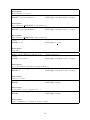
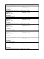
A crosstool chain is a tool chain to create and manipulate binary programs for a target architecture and operating system (e.g. PowerPC/Linux) that are different from host architecture and
operating system (e.g. x86/Linux) that runs the tool chain. Building a GNU crosstool chain
from scratch is a very tedious task. The process consists of a quite high number of undocumented steps, and mostly relies on the users experience. Fortunately a community sharing its
experience, the crossgcc mailing list, actively supports a tool, crosstool-NG, that considerably
simplifies the process of building a crosstool chain. Xilinx Virtex-5 FXT embedded processor
is a PPC440x5 and Xilinx Platform Studio provides a PowerPC hardware FPU. Hence, from
now, we will focus our effort on creating a crosstool chain with GNU GCC 4.4.6 (gcc and g++),
GNU C library 2.9 (glibc), GNU binutils 2.19.1 (ld, objdump, and readelf), and GNU GDB
6.8 (gdb) for target powerpc-440fp-linux-gnu.
1. Get crosstool-NG: Download the crosstool-NG archive (e.g crosstool-ng-1.11.3.tar.bz2)
from this page: http://crosstool-ng.org
2. Uncompress crosstool-NG archive:
$ tar jxvf crosstool-ng-1.11.3.tar.bz2
13
3. Configure crosstool-NG build:
$ cd crosstool-ng-1.11.3
$ ./configure --local
4. Compile crosstool-NG
$ make
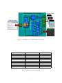
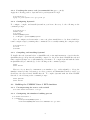
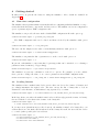
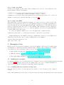
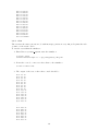
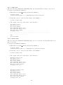
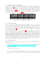
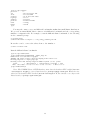
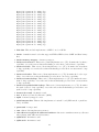
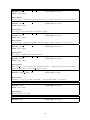
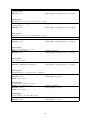
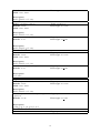
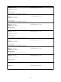
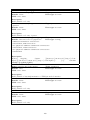
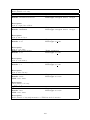
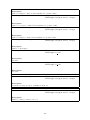
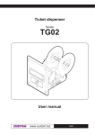
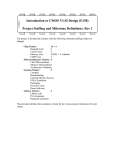
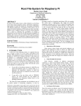
5. Configure the crosstool chain build as shown on Figure 2:
$ ./ct-ng menuconfig
6. Build the crosstool chain (this may take tens of minutes):
$ ./ct-ng build
7. You crosstool chain is ready in ${HOME}/crosstool/powerpc-440fp-linux-gnu
14
Paths and misc options --->
(${HOME}/crosstool/powerpc-440fp-linux-gnu) Prefix directory
Target options --->
Target Architecture (powerpc) --->
(440fp) Emit assembly for CPU
(440fp) Tune for CPU
Floating point: (hardware (FPU)) --->
Toolchain options --->
(440fp) Tuple’s vendor string
Operating System --->
Target OS (linux) --->
Linux kernel version (2.6.35.13 (longterm))
Binary utilities --->
binutils version (2.19.1)
--->
--->
[*] binutils libraries for the target
[*]
libiberty (NEW)
[*]
libbfd (NEW)
C compiler --->
gcc version (4.4.6) --->
[*] C++
[ ] Link libstdc++ statically into the gcc binary
C-library --->
C library (glibc) --->
glibc version (2.9) --->
(-U_FORTIFY_SOURCE) extra target CFLAGS
[*] Use the ports addon
Debug facilities --->
[*] gdb --->
Companion libraries --->
MPFR version (2.4.2) --->
CLooG/ppl version (0.15.9)
--->
Figure 2: crosstool chain build configuration (changes from default only) for Crosstool-NG
1.11.3.
15
4.5.2
Using cross-GCC
A GCC cross-compiler together with a LD cross-linker can be used to create binaries for the
target machine from the host machine:
$ ${HOME}/crosstool/powerpc-440fp-linux-gnu/bin/powerpc-440fp-linux-gnu-gcc \
nodefaultlibs -nostdlib -mcpu=440fp -c hello.c -o hello.o
$ ${HOME}/crosstool/powerpc-440fp-linux-gnu/bin/powerpc-440fp-linux-gnu-ld hello.lds -o hello.elf
Simulator can directly loads such binary files, see Section 4.2.
4.5.3
Using cross-GDB
GNU GDB client can debug applications running on a remote/local host on the network. The
application is run under the control of program gdbserver while program gdb only manages interactions with the user. Program gdbserver and gdb communicates over the TCP/IP network
using a documented serial remote protocol. The simulator has a GDB server service that implements the GDB serial remote protocol, so that the simulator can acts as Program gdbserver
from the GDB client point of view.
To enable the simulator GDB server, do the following at the command prompt:
$ unisim-virtex5fxt-wfpu-1.0 -s enable-gdb-server=true -s gdb-server.tcp-port=1234
During initialization, the simulator waits for a GDB client connection on the GDB server
TCP/IP port. In another console, connect a GDB client to the simulator:
$ powerpc-440fp-linux-gnu-gdb boot.elf
(gdb) target remote :1234
5
Examples of use
In this section, we present some examples of use for the simulator. We provide you with scripts
and makefiles to build in an automatic manner all the examples. These examples are available
for download in source and binary forms on our web site (http://unisim-vp.org):
• Basic system level unit tests: [hyperlink to binaries], [hyperlink to sources]
• MiBench version 1: [hyperlink to binaries], [hyperlink to sources]
• light weight Linux distribution: [hyperlink to binaries], [hyperlink to sources]
5.1
Building the examples
To build the examples you need a functional cross tool-chain for target for target powerpc-440fp-linux-gnu,
see Section 4.5.1. In later sub-sections, we assume that your cross tool-chain is installed in
/opt/crosstool/gcc-4.4.6-glibc-2.9/powerpc-440fp-linux-gnu
5.1.1
Building the basic system level unit tests
From the directory where you uncompressed the archive, do the following at the command
prompt:
$ make CROSS_COMPILE=/opt/crosstool/gcc-4.4.6-glibc-2.9/powerpc-440fp-linux-gnu/bin/powerpc-440fp-linux-gnu-
16
5.1.2
Building the MiBench version 1 benchmarks
From the directory where you uncompressed the archive, do the following at the command
prompt:
./build.sh all /opt/crosstool/gcc-4.4.6-glibc-2.9/powerpc-440fp-linux-gnu
5.1.3
Building the light weight Linux distribution
From the directory where you uncompressed the archive, do the following at the command
prompt:
./build.sh all /opt/crosstool/gcc-4.4.6-glibc-2.9/powerpc-440fp-linux-gnu
5.2
Basic system level tests
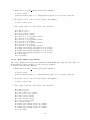
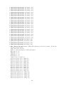
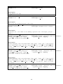
Table 2 shows a summary of basic system tests.
17
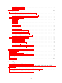
Table 2: Summary of basic system level tests.
18
√
√
√
√
√
√
√
√
√
√
√
√
√
√
√
√
√
√
√
√
√
√
√
√
√
√
√
√
√
√
NOR Flash
UART Lite
√
Timer
Directory
xps uart lite/echo
xps timer/poll
xps timer/gen
xps timer/cap
xps timer/pwm
s29gl256p/autoselect
s29gl256p/cfi query
s29gl256p/chip erase
s29gl256p/sector erase
s29gl256p/single word programming
s29gl256p/unlock bypass chip erase
s29gl256p/unlock bypass sector erase
s29gl256p/unlock bypass word programming
s29gl256p/write buffer programming
IntC
Test Name
Echo
Poll
Gen
Cap
PWM
Autoselect
CFI query
Chip erase
Sector erase
Single word programming
Unlock bypass chip erase
Unlock bypass sector erase
Unlock bypass word programming
Write buffer programming
√
√
√
√
√
√
√
√
√
5.2.1
Echo
The test reads characters from the serial console. It prints the read characters on the serial
console.
1. At the command prompt, do the following:
$ cd basic_system
$ unisim-virtex5fxt-wfpu-1.0 -c xps_uart_lite/echo/sim_config.xml
2. In another console, do the following at command prompt:
$ telnet localhost 1234
3. Press some keys in the telnet console. The corresponding characters should prints in the
telnet console as you type
5.2.2
Poll
The test polls the timer/counter #0. It prints some of the sampled values on the serial console.
To run the test within the simulator:
1. Enter Directory basic system, start the simulator:
$ cd basic_system
$ unisim-virtex5fxt-wfpu-1.0 -c xps_timer/poll/sim_config.xml
2. In another console, connect a telnet client to the simulator:
$ telnet localhost 1234
3. The output of the test on the telnet console should be:
Time
Time
Time
Time
Time
Time
Time
Time
Time
Time
Time
Time
Time
Time
Time
Time
Time
Time
Time
Time
Time
Time
Time
Time
Time
is
is
is
is
is
is
is
is
is
is
is
is
is
is
is
is
is
is
is
is
is
is
is
is
is
6 us
116 us
227 us
338 us
449 us
560 us
671 us
782 us
893 us
1004 us
1115 us
1226 us
1337 us
1448 us
1559 us
1670 us
1782 us
1893 us
2004 us
2115 us
2226 us
2337 us
2448 us
2559 us
2670 us
19
Time
Time
Time
Time
Time
Time
Time
Time
Time
Time
Time
Time
Time
Time
Time
Test
5.2.3
is
is
is
is
is
is
is
is
is
is
is
is
is
is
is
is
2782 us
2894 us
3005 us
3116 us
3228 us
3340 us
3451 us
3562 us
3673 us
3785 us
3897 us
4008 us
4119 us
4230 us
4342 us
finished
Gen
The test uses the timer generate mode with interrupt generation every 100 µs. It prints the tick
of timer on the serial console.
To run the test within the simulator:
1. Enter Directory basic system, start the simulator:
$ cd basic_system
$ unisim-virtex5fxt-wfpu-1.0 -c xps_timer/gen/sim_config.xml
2. In another console, connect a telnet client to the simulator:
$ telnet localhost 1234
3. The output of the test on the telnet console should be:
Tick:
Tick:
Tick:
Tick:
Tick:
Tick:
Tick:
Tick:
Tick:
Tick:
Tick:
Tick:
Tick:
Tick:
Tick:
Tick:
....
....
Tick:
Tick:
Tick:
Tick:
Tick:
Tick:
Tick:
Tick:
100 us
200 us
300 us
400 us
500 us
600 us
700 us
800 us
900 us
1000 us
1100 us
1200 us
1300 us
1400 us
1500 us
1600 us
8300
8400
8500
8600
8700
8800
8900
9000
us
us
us
us
us
us
us
us
20
Tick: 9100 us
Tick: 9200 us
Tick: 9300 us
Tick: 9400 us
Tick: 9500 us
Tick: 9600 us
Tick: 9700 us
Tick: 9800 us
Tick: 9900 us
Tick: 10000 us
Test is finished
5.2.4
Cap
The test uses the timer capture mode (randomized input between 1 µs and 3.995 µs). It prints
the captured time stamp on the serial console.
To run the test within the simulator:
1. Enter Directory basic system, start the simulator:
$ cd basic_system
$ unisim-virtex5fxt-wfpu-1.0 -c xps_timerp/cap/sim_config.xml
2. In another console, connect a telnet client to the simulator:
$ telnet localhost 1234
3. The output of the test on the telnet console should be:
Last
Last
Last
Last
Last
Last
Last
Last
Last
Last
Last
Last
Last
Last
Last
Last
Last
Last
Last
Last
Last
Last
Last
Last
Last
Last
Last
Last
Last
Last
Last
Last
capture
capture
capture
capture
capture
capture
capture
capture
capture
capture
capture
capture
capture
capture
capture
capture
capture
capture
capture
capture
capture
capture
capture
capture
capture
capture
capture
capture
capture
capture
capture
capture
is
is
is
is
is
is
is
is
is
is
is
is
is
is
is
is
is
is
is
is
is
is
is
is
is
is
is
is
is
is
is
is
360 ns
23090 ns
45930 ns
69285 ns
93040 ns
117545 ns
143545 ns
169325 ns
195480 ns
220590 ns
244635 ns
270840 ns
294800 ns
319990 ns
348385 ns
370810 ns
397785 ns
422900 ns
449070 ns
473000 ns
497565 ns
521180 ns
547700 ns
572140 ns
596700 ns
622295 ns
647230 ns
671745 ns
697080 ns
722645 ns
746020 ns
771475 ns
21
Last
Last
Last
Last
Last
Last
Last
Last
Last
Last
Test
5.2.5
capture is 797765 ns
capture is 818050 ns
capture is 847275 ns
capture is 872910 ns
capture is 897765 ns
capture is 922820 ns
capture is 947330 ns
capture is 972370 ns
capture is 998170 ns
capture is 1024420 ns
is finished
PWM
The test uses the timer in PWM (Pulse Width Modulation) mode with a period of 2 µs and a
duty cycle of 300 ns. To run the test within the simulator:
1. Enter Directory basic system, start the simulator and filter PWM0 activity:
$ cd basic_system
$ unisim-virtex5fxt-wfpu-1.0 -c xps_timer/pwm/sim_config.xml \
-s timer.verbose=true | grep ’PWM0 signal’
2. In another console, connect a telnet client to the simulator:
$ telnet localhost 1234
3. The output of the test on the telnet console should be:
You should observe a PWM output with a period of 2000 ns, and a duty cycle of 300 ns.
timer:
timer:
timer:
timer:
timer:
timer:
timer:
timer:
timer:
timer:
timer:
timer:
timer:
timer:
timer:
timer:
timer:
timer:
timer:
timer:
timer:
timer:
timer:
timer:
timer:
timer:
timer:
timer:
....
7815 ns: PWM0 signal goes high
8115 ns: PWM0 signal goes low
9815 ns: PWM0 signal goes high
10115 ns: PWM0 signal goes low
11815 ns: PWM0 signal goes high
12115 ns: PWM0 signal goes low
13815 ns: PWM0 signal goes high
14115 ns: PWM0 signal goes low
15815 ns: PWM0 signal goes high
16115 ns: PWM0 signal goes low
17815 ns: PWM0 signal goes high
18115 ns: PWM0 signal goes low
19815 ns: PWM0 signal goes high
20115 ns: PWM0 signal goes low
21815 ns: PWM0 signal goes high
22115 ns: PWM0 signal goes low
23815 ns: PWM0 signal goes high
24115 ns: PWM0 signal goes low
25815 ns: PWM0 signal goes high
26115 ns: PWM0 signal goes low
27815 ns: PWM0 signal goes high
28115 ns: PWM0 signal goes low
29815 ns: PWM0 signal goes high
30115 ns: PWM0 signal goes low
31815 ns: PWM0 signal goes high
32115 ns: PWM0 signal goes low
33815 ns: PWM0 signal goes high
34115 ns: PWM0 signal goes low
22
5.2.6
Autoselect
The test puts the S29GL256P NOR Flash chip in autoselect mode. It reads the manufacturer
and device IDs. It prints the two IDs on the serial console. It prints also protection status of
each sector.
To run the test within the simulator:
1. Enter Directory basic system, and start the simulator:
$ cd basic_system
$ unisim-virtex5fxt-wfpu-1.0 -c s29gl256p/autoselect/sim_config.xml
2. In another console, connect a telnet client to the simulator:
$ telnet localhost 1234
3. The output of the test on the telnet console should be:
Write unlock cycle 1
Write unlock cycle 2
Write autoselect command
Manufacturer ID: 0x0001
Device ID word 1: 0x227e
Device ID word 2: 0x2222
Device ID word 3: 0x2201
Protection status (U=unprotected/P=protected): UUUUUUUUUUUUUUUUUUUUUUUUUUUUUUUUU
UUUUUUUUUUUUUUUUUUUUUUUUUUUUUUUUUUUUUUUUUUUUUUUUUUUUUUUUUUUUUUUUUUUUUUUUUUUUUUUU
UUUUUUUUUUUUUUUUUUUUUUUUUUUUUUUUUUUUUUUUUUUUUUUUUUUUUUUUUUUUUUUUUUUUUUUUUUUUUUUU
UUUUUUUUUUUUUUUUUUUUUUUUUUUUUUUUUUUUUUUUUUUUUUUUUUUUUUUUUUUUUUU
Exit autoselect
Test is finished
5.2.7
CFI query
The test puts the S29GL256P NOR Flash chip in CFI (Common Flash Interface) query mode.
It queries the unique ASCII string ”QRY”. For each of the three characters, it prints on the
serial console whether they match what is expected (”QRY”).
To run the test within the simulator:
1. Enter Directory basic system, and start the simulator:
$ cd basic_system
$ unisim-virtex5fxt-wfpu-1.0 -c s29gl256p/cfi_query/sim_config.xml
2. In another console, connect a telnet client to the simulator:
$ telnet localhost 1234
3. The output of the test on the telnet console should be:
Write CFI entry command
Read Q: OK
Read R: OK
Read Y: OK
Exit CFI query mode (Write reset command)
Test is finished
23
5.2.8
Chip erase
The test erases the S29GL256P NOR Flash chip. It checks that all sectors have been erased.
To run the test within the simulator:
1. Enter Directory basic system, and start the simulator:
$ cd basic_system
$ unisim-virtex5fxt-wfpu-1.0 -c s29gl256p/chip_erase/sim_config.xml
2. In another console, connect a telnet client to the simulator:
$ telnet localhost 1234
3. The output of the test on the telnet console should be:
Write unlock cycle 1
Write unlock cycle 2
Write setup command
Write additional unlock cycle 1
Write additional unlock cycle 2
Write chip erase command
Verifying sectors..............................................................
...............................................................................
...............................................................................
....................................
Done
Test is finished
5.2.9
Sector erase
The test erases the S29GL256P NOR Flash chip, one sector at a time. It checks that all sectors
have been erased.
To run the test within the simulator:
1. Enter Directory basic system, and start the simulator:
$ cd basic_system
$ unisim-virtex5fxt-wfpu-1.0 -c s29gl256p/sector_erase/sim_config.xml
2. In another console, connect a telnet client to the simulator:
$ telnet localhost 1234
3. The output of the test on the telnet console should be:
Erasing sector #0 of 256
Write unlock cycle 1
Write unlock cycle 2
Write setup command
Write additional unlock cycle 1
Write additional unlock cycle 2
Write sector erase command
Verifying sector: OK
....
....
Erasing sector #255 of 256
Write unlock cycle 1
Write unlock cycle 2
Write setup command
Write additional unlock cycle 1
Write additional unlock cycle 2
Write sector erase command
Verifying sector: OK
24
5.2.10
Single word programming
The test program a word on the S29GL256P NOR Flash chip. It verifies that word has been
effectively programmed.
To run the test within the simulator:
1. Enter Directory basic system, and start the simulator:
$ cd basic_system
$ unisim-virtex5fxt-wfpu-1.0 -c s29gl256p/single_word_programming/sim_config.xml
2. In another console, connect a telnet client to the simulator:
$ telnet localhost 1234
3. The output of the test on the telnet console should be:
Write unlock cycle 1
Write unlock cycle 2
Write program setup command
Write data to be programmed
Verify programmed data: OK
5.2.11
Unlock bypass chip erase
The test erases the S29GL256P NOR Flash chip four times. It checks that all sectors have been
erased.
To run the test within the simulator:
1. Enter Directory basic system, and start the simulator:
$ cd basic_system
$ unisim-virtex5fxt-wfpu-1.0 -c s29gl256p/unlock_bypass_chip_erase/sim_config.xml
2. In another console, connect a telnet client to the simulator:
$ telnet localhost 1234
3. The output of the test on the telnet console should be:
Write unlock cycle 1
Write unlock cycle 2
Write unlock bypass command
=== Pass #0 ===
Write setup command
Write chip erase command
Verifying sectors...............................................................
................................................................................
................................................................................
.................................
Done
=== Pass #1 ===
Write setup command
Write chip erase command
Verifying sectors...............................................................
................................................................................
................................................................................
.................................
25
Done
=== Pass #2 ===
Write setup command
Write chip erase command
Verifying sectors...............................................................
................................................................................
................................................................................
.................................
Done
=== Pass #3 ===
Write setup command
Write chip erase command
Verifying sectors...............................................................
................................................................................
................................................................................
.................................
Done
Exit unlock bypass
Test is finished
5.2.12
Unlock bypass sector erase
The test erases the S29GL256P NOR Flash chip, one sector at a time. It checks that all sectors
have been erased.
To run the test within the simulator:
1. Enter Directory basic system, and start the simulator:
$ cd basic_system
$ unisim-virtex5fxt-wfpu-1.0 -c s29gl256p/unlock_bypass_sector_erase/sim_config.xml
2. In another console, connect a telnet client to the simulator:
$ telnet localhost 1234
3. The output of the test on the telnet console should be:
Write unlock cycle 1
Write unlock cycle 2
Write unlock bypass command
Erasing sector #0 of 256
Write setup command
Write sector erase command for sector #0
Verifying sector: OK
....
....
Erasing sector #255 of 256
Write setup command
Write sector erase command for sector #255
Verifying sector: OK
Exit unlock bypass
Test is finished
5.2.13
Unlock bypass word programming
The test programs four words in the S29GL256P NOR Flash chip, one word at a time. It verifies
that the four words have beed effectively programmed.
To run the test within the simulator:
26
1. Enter Directory basic system, and start the simulator:
$ cd basic_system
$ unisim-virtex5fxt-wfpu-1.0 -c s29gl256p/unlock_bypass_sector_erase/sim_config.xml
2. In another console, connect a telnet client to the simulator:
$ telnet localhost 1234
3. The output of the test on the telnet console should be:
Write unlock cycle 1
Write unlock cycle 2
Write unlock bypass command
Write program setup command
Write data #0 to be programmed (0x4321)
Write program setup command
Write data #1 to be programmed (0x8765)
Write program setup command
Write data #2 to be programmed (0x9087)
Write program setup command
Write data #3 to be programmed (0x3852)
Re-reading and Verifying programmed data:
Re-reading and Verifying programmed data:
Re-reading and Verifying programmed data:
Re-reading and Verifying programmed data:
Exit unlock bypass
Test is finished
5.2.14
OK
OK
OK
OK
(0x4321)
(0x8765)
(0x9087)
(0x3852)
Write buffer programming
The test programs four words in the S29GL256P NOR Flash chip, using the write buffer. It
verifies that the four words have beed effectively programmed.
To run the test within the simulator:
1. Enter Directory basic system, and start the simulator:
$ cd basic_system
$ unisim-virtex5fxt-wfpu-1.0 -c s29gl256p/unlock_bypass_sector_erase/sim_config.xml
2. In another console, connect a telnet client to the simulator:
$ telnet localhost 1234
3. The output of the test on the telnet console should be:
Write unlock cycle 1
Write unlock cycle 2
Write write buffer load command
Write write word count (minus 1)
Write data word #0 (0x4321)
Write data word #1 (0x8765)
Write data word #2 (0x9087)
Write data word #3 (0x3852)
Write confirm command
Re-reading and verifying word #0:
Re-reading and verifying word #1:
Re-reading and verifying word #2:
Re-reading and verifying word #3:
Test is finished
OK
OK
OK
OK
(0x4321)
(0x8765)
(0x9087)
(0x3852)
27
5.3
A light weight Linux distribution
The simulator can easily run a minimalist Linux distribution for a Xilinx Virtex-5 FXT development board. Table 3 shows the files to load in the simulator to run such a minimalist Linux
distribution. In later sub-sections, we explain how these files are obtained. We provides you with
prebuilt files to allow you quickly boot a minimalist Linux distribution within the simulator.
Go directly to Sub-section 5.3.7 if you don’t bother about the technique behind creating a light
weight Linux distribution for the simulator. To build such a minimalist Linux distribution, you
need a working crosstool chain, see Section 4.5.1.
File
boot.elf
vmlinux
device tree.dtb
initrd.img
Start address
0xffff0000
0x00000000
0x00800000
0x00900000
Memory
BRAM
RAM
RAM
RAM
Description
Boot program
Linux kernel
Device Tree
Initial RAM disk
Table 3: Files for booting Linux in the simulator.
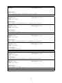
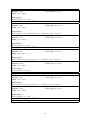
5.3.1
The boot program
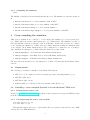
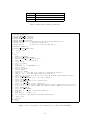
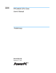
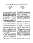
The boot program is loaded in BRAM which is behind the MPLB. At reset, the processor starts
executing instructions from physical address 0xfffffffc. Thus the boot program is located in
memory so that it has an instruction (usually a branch) at that physical address. The role of
the boot program is to initialize early boot and provides the Kernel with some parameters in
the processor registers. Table 4 shows the registers that needs to be initialized before branching
into the Linux Kernel entry point.
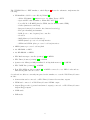
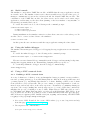
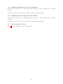
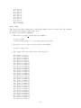
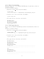
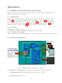
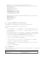
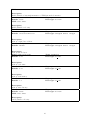
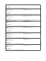
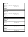
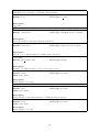
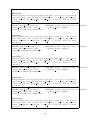
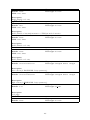
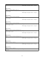
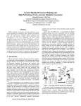
The boot program, which source is shown on Figure 3, has been designed to make instruction
at Label start match the processor start address. Actually, a branch instructions to elsewhere
in the boot program (Label init) is placed at the reset address. The boot program then starts
enabling the MCI (Memory Controller Interface) so that processor can use RAM which is behind
the MCI. It programs the MMU to map the whole 256 MB RAM in the processor address space.
It initializes required register parameters of the Linux kernel, that is the device tree address into
Register r3, the initial RAM disk address range into Registers r4 and r5, the Linux kernel start
address into Register SRR0, and the value of MSR into Register SRR1. It then branches to the
Linux kernel using an rfi instruction (return from interrupt).
5.3.2
The Linux kernel
The Linux kernel (aka. vmlinux) must be configured and built for the target platform. The
steps to follow are:
1. Get the Linux kernel source code: Download the linux-2.6.38.7.tar.bz2 tarball at
ftp://ftp.kernel.org/pub/linux/kernel/v2.6/linux-2.6.38.7.tar.bz2.
2. Uncompress the tarball
$ tar jxvf linux-2.6.38.7.tar.bz2
3. Before starting configuring the Linux kernel build, we need to modify a Linux configuration
file to enable support of hardware FPU. In File arch/powerpc/platforms/44x/Kconfig,
after:
28
Registers
r3
r4
r5
Description
Address of the device tree
Start address of the initial RAM disk
End address of the initial RAM disk
Table 4: Linux kernel register parameters.
1
2
3
4
5
6
7
8
9
10
11
12
13
14
15
16
17
18
19
20
21
22
23
24
25
26
27
28
29
30
31
32
33
34
35
36
37
38
39
40
41
42
43
44
45
46
47
48
49
50
#include "ppc44x regs.h"
#define KERNEL START 0x00000000
#define DEV TREE PTR 0x00800000
#define INITRD START 0x00900000
#define INITRD END 0x01900000
#define TLB0 0x00000250 /* map 0x00000000 (256 MB) in system address space */
#define TLB1 0x0
/* at physical address 0x0 */
#define TLB2 0x7
/* with access control SX=1 SW=1 SR=1 */
#define MI CONTROL 0x10
#define MI CONTROL ENABLE 0x8000
.section ".text"
.org 0
init:
mfdcr r0, MI CONTROL
oris r0, r0, MI CONTROL ENABLE
mtdcr MI CONTROL, r0
/* enable MCI */
li r0, 0
/* TLB entry #0 */
lis r8, TLB0@h
ori r8, r8, TLB0@l
li r9, 0
mtspr MMUCR, r9
/* MMUCR[STID] = 0 */
lis r10, TLB1@h
ori r10, r10, TLB1@l
lis r11, TLB2@h
ori r11, r11, TLB2@l
tlbwe r8, r0, 0
/* Set EPN, V, TS, SIZE, TID of UTLB entry #0 word #0 */
tlbwe r10, r0, 1 /* Set RPN, ERPN of UTLB entry #0 word #1 */
tlbwe r11, r0, 2 /* Set U0 U1 U2 U3 W I M G E UX UW UR SX SW SR of UTLB entry #0 word #2 */
lis r3, DEV TREE PTR@h
ori r3, r3, DEV TREE PTR@l /* r3 <- device tree address */
lis r4, INITRD START@h
ori r4, r4, INITRD START@l /* r4 <- initrd start */
lis r5, INITRD END@h
ori r5, r5, INITRD END@l /* r5 <- initrd end */
li r6, 0 /* r6 <- start of kernel command line (unused as kernel command line is in dev tree) */
li r7, 0 /* r7 <- end of kernel command line (unused as kernel command line is in dev tree) */
lis r0, KERNEL START@h
ori r0, r0, KERNEL START@l
mtspr SRR0, r0
/* SRR0 <- kernel start address */
li r1, 0
mtspr SRR1, r1
/* MSR <- 0 */
rfi
/* Branch to Linux kernel and invalidate shadow TLBs */
.global start
.org 0xffc
start:
b init
Figure 3: Boot program (boot.S compiled as boot.elf) loaded in BRAM.
29
config XILINX_VIRTEX_5_FXT
bool
select XILINX_VIRTEX
add the following line:
select PPC_FPU
4. We can now configure the Linux kernel build:
$ make \
ARCH=powerpc \
CROSS_COMPILE=${HOME}/crosstool/powerpc-440fp-linux-gnu/bin/powerpc-440fp-linux-gnu- \
V=1 menuconfig
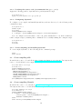
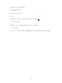
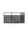
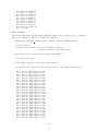
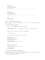
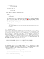
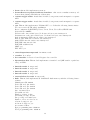
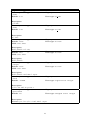
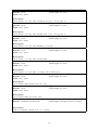
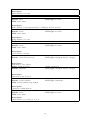
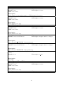
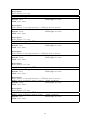
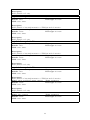
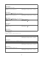
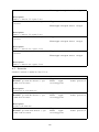
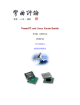
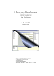
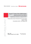
The Linux kernel should be configured as shown on Figure 4. Once configuration is finished,
at exit don’t forget to answer ”Yes” when prompted for saving the settings in File .config.
5. The Linux kernel (vmlinux) can now be built. The build may take tens of minutes. Do
the following at the command prompt:
$ make \
ARCH=powerpc \
CROSS_COMPILE=${HOME}/crosstool/powerpc-440fp-linux-gnu/bin/powerpc-440fp-linux-gnu- \
V=1 vmlinux
5.3.3
The device Tree
On PowerPC embedded platforms, the Linux kernel uses a hierarchical list of devices, namely a
device tree where leaves are devices and non-leaf nodes are buses, bridges and interconnects. It
is a rather detailed machine description to allow the Linux kernel to correctly initialize devices
and route interrupts to the interrupt routines. The boot loader or anything else launching the
Linux kernel should provide the Linux kernel with the device tree. Linux provides a device tree
compiler that compile a text description (.dts file) in a loadable binary form (.dtb file). Our
example provides user with three device trees, that is one for each initial RAM disk size (16
MB, 32 MB and 64 MB). The provided device trees are:
1. device-tree-16m.dtb: device tree for a 16 MB large initial RAM disk
2. device-tree-32m.dtb: device tree for a 32 MB large initial RAM disk
3. device-tree-64m.dtb: device tree for a 64 MB large initial RAM disk
5.3.4
The initial RAM disk
The initial RAM disk file is a file containing an image of the root file system. We consider
creating an initial RAM disk with an Ext2 file system in it. Note that creating an image
requires root privileges because mounting a file system requires root privileges.
The steps to follow are:
1. Create an empty image (initrd.img) of 16 MB:
[root@localhost] $ dd if=/dev/zero of=initrd.img count=16384 bs=1024
2. Create an Ext2 file system in image:
30
Processor support --->
Processor Types (AMCC 44x, 46x or 47x)
General Setup --->
[*] Initial RAM filesystem and RAM disk (initramfs/initrd) support
Platform support --->
[*] Generic Xilinx Virtex 5 FXT board support
Device Drivers --->
[*] Block devices --->
(16)
Default number of RAM disks
(65536) Default RAM disk size (kbytes)
Character devices --->
Serial drivers --->
<*> Xilinx uartlite serial port support
[*]
Support for console on Xilinx uartlite serial port
[*] GPIO Support --->
[*] Xilinx GPIO support
[*] Watchdog Timer Support --->
<*> PowerPC Book-E Watchdog Timer
File systems --->
<*> Second extended fs support
Kernel hacking --->
[*] Compile the kernel with debug info
Figure 4: Linux kernel configuration (changes from default only).
31
[root@localhost] $ mke2fs -F -m 0 initrd.img
3. Create a mount point and mount image on it:
[root@localhost] $ mkdir /media/initrd
[root@localhost] $ mount -o loop initrd.img /mnt/initrd
4. Now you can directly access withing the image using directory /mnt/initrd. In directory
/mnt/initrd, copy every files and directories you want in your image.
5. Unmount image:
[root@localhost] $ umount /media/initrd
We provide several prebuilt initial RAM disks. Some of the initial RAM disks contain a
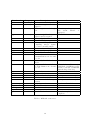
MiBench benchmark (see Table 6) in /opt. Table 5 summarizes the prebuilt initial RAM disks.
Initial RAM disk
initrd.img
initrd automotive basicmath.img
initrd consumer typeset.img
initrd office rsynth.img
initrd telecomm adpcm.img
initrd automotive bitcount.img
initrd office stringsearch.img
initrd telecomm crc32.img
initrd automotive qsort.img
initrd network dijkstra.img
initrd security blowfish.img
initrd telecomm fft.img
initrd automotive susan.img
initrd network patricia.img
initrd security pgp.img
initrd telecomm gsm.img
initrd consumer jpeg.img
initrd office ghostscript.img
initrd security rijndael.img
initrd consumer lame.img
initrd office ispell.img
initrd security sha.img
Busybox
Busybox
Busybox
Busybox
Busybox
Busybox
Busybox
Busybox
Busybox
Busybox
Busybox
Busybox
Busybox
Busybox
Busybox
Busybox
Busybox
Busybox
Busybox
Busybox
Busybox
Busybox
Content
only
+ automotive/basicmath
+ consumer/typeset
+ office/rsynth
+ telecomm/ADPCM
+ automotive/bitcount
+ office/stringsearch
+ telecomm/CRC32
+ automotive/qsort
+ network/dijkstra
+ security/blowfish
+ telecomm/FFT
+ automotive/susan
+ network/patricia
+ security/PGP
+ telecomm/GSM
+ consumer/JPEG MiBench
+ office/ghostscript
+ security/rijndael
+ consumer/lame
+ office/ispell
+ security/sha
Table 5: Initial RAM disks.
32
5.3.5
Busybox
Busybox is a light weight shell that includes most of standard UNIX commands. Actually
commands are symbolic links to the busybox binary. Busybox knows which commands to
implement looking at its argv[0]. It is usually a good idea to install Busybox in the initial
RAM disk image of an Linux-based embedded platform because it’s tiny and easy to crosscompile. The Linux kernel (vmlinux), at the end of the boot procedure, starts linuxrc located
at the root of the root file system (e.g. in an initial RAM disk on device /dev/ram0). Usually
linuxrc is a symbolic link to the boot shell (e.g. the Busybox ash shell located at /bin/ash).
5.3.6
The MiBench version 1 benchmarks
The MiBench [13, 1] version 1 is a free, commercially representative embedded benchmark suite.
Most of the benchmarks come with small and large data sets. Table 6 summarizes the available
benchmarks and there current status. Be aware that some of the benchmarks are so difficult
to cross-compile (they were only intended to be natively compiled on the machine that will run
them) that we gave up to build them. Also note that some benchmarks do not run correctly on
PowerPC processors because these benchmarks wrongly assumes endian (PowerPC processors
natural endian is big-endian whether processors of standard PC are little-endian). When such
limitations exist, they are explained in the status column of the table.
5.3.7
Running the example
A very small Linux distribution based on Busybox together with a configuration file are provided
for the simulator. To boot that small Linux distribution within the simulator, do the following
at the command prompt:
$ cd linux_distro
$ unisim-virtex5fxt-1.0-wfpu-1.0 -c sim_config.xml
The simulator acts as a telnet server to emulate a terminal over the XPS UART Lite. Once
started, it waits for a telnet client connection like telnet or PuTTY. To connect the telnet client
to the simulator, do the following at the command prompt:
$ telnet localhost 1234
You can see (in the telnet terminal) the Linux distribution booting in the simulator:
[
0.000000] Using Xilinx Virtex440 machine description
[
0.000000] Linux version 2.6.38.7 ([email protected]) (gcc version
4.4.6 (crosstool-NG-1.11.3) ) #1 PREEMPT Thu Sep 8 10:28:23 CEST 2011
[
0.000000] Found initrd at 0xc0900000:0xc1900000
[
0.000000] Zone PFN ranges:
[
0.000000]
DMA
0x00000000 -> 0x00001000
[
0.000000]
Normal
empty
[
0.000000] Movable zone start PFN for each node
[
0.000000] early_node_map[1] active PFN ranges
[
0.000000]
0: 0x00000000 -> 0x00001000
[
0.000000] MMU: Allocated 1088 bytes of context maps for 255 contexts
[
0.000000] Built 1 zonelists in Zone order, mobility grouping off. Total pages: 4094
[
0.000000] Kernel command line: root=/dev/ram0 rw init=linuxrc console=ttyUL0
[
0.000000] PID hash table entries: 1024 (order: -4, 4096 bytes)
[
0.000000] Dentry cache hash table entries: 32768 (order: 1, 131072 bytes)
[
0.000000] Inode-cache hash table entries: 16384 (order: 0, 65536 bytes)
[
0.000000] Memory: 240192k/262144k available (3712k kernel code, 21952k reserved,
384k data, 689k bss, 256k init)
[
0.000000] Kernel virtual memory layout:
[
0.000000]
* 0xfffd0000..0xffff0000 : fixmap
[
0.000000]
* 0xfde00000..0xfe000000 : consistent mem
33
Benchmark
sha
blowfish
Category
security
security
rijndael
security
pgp
security
qsort
susan
basicmath
automotive
automotive
automotive
bitcount
dijkstra
FFT
GSM
automotive
network
telecomm
telecomm
CRC32
telecomm
ADPCM
telecomm
typeset
lame
mad
JPEG
tiff
consumer
consumer
consumer
consumer
office
ghostscript
ispell
stringsearch
rsynth
sphinx
office
office
office
office
office
Description
160-bit secure hash algorithm
Blowfish encryption and decryption
AES encryption and decryption
Asymetric (public key) encryption and decryption
Sorting algorithm
Corner and edge recognition
Solving cubic polynomial,
computing integer square
root and converting angles
Count set bits in integer
Shortest path in a graph
Fast Fourier Transform
Global System for Mobile
Communications encoder and
decoder
32-bit Cyclic Redundancy
Check
Adaptative Differential Pulse
Code Modulation encoder and
decoder
A batch document formatter
MP3 encoder
MPEG audio decoding
JPEG encoder and decoder
Conversion and Dithering of
pictures
Postscript renderer
Spell checker
Search for words in text
Text to speech synthesis
Speech decoder
Table 6: MiBench version 1.0.
34
Status
OK
OK
OK after patching aesxam.c
(use
ftell
instead
of
fgetpos)
OK
OK
OK
OK
OK
OK
OK
OK
OK
OK with the small data set (a
RAM disk of 64 MB is not sufficient to run the benchmark
with the large data set)
OK
OK
Can’t get it to cross-compile
OK
Can’t get it to cross-compile
Crashes on PowerPC
OK
OK
OK
Can’t be compiled on modern
compilers
[
0.000000]
* 0xfde00000..0xfde00000 : early ioremap
[
0.000000]
* 0xd1000000..0xfde00000 : vmalloc & ioremap
[
0.000000] Preemptable hierarchical RCU implementation.
[
0.000000] RCU-based detection of stalled CPUs is disabled.
[
0.000000] Verbose stalled-CPUs detection is disabled.
[
0.000000] NR_IRQS:512
[
0.000000] clocksource: timebase mult[a00000] shift[22] registered
[
0.000000] Console: colour dummy device 80x25
[
0.000343] pid_max: default: 32768 minimum: 301
[
0.000814] Mount-cache hash table entries: 8192
[
0.007584] NET: Registered protocol family 16
[
0.009029] PCI: Probing PCI hardware
[
0.017297] bio: create slab <bio-0> at 0
[
0.017779] XGpio: /plb@0/gpio@81460000: registered
[
0.017978] XGpio: /plb@0/gpio@81400000: registered
[
0.018185] XGpio: /plb@0/gpio@81420000: registered
[
0.018389] XGpio: /plb@0/gpio@81440000: registered
[
0.018872] vgaarb: loaded
[
0.019767] Switching to clocksource timebase
[
0.035481] NET: Registered protocol family 2
[
0.035774] IP route cache hash table entries: 16384 (order: 0, 65536 bytes)
[
0.037037] TCP established hash table entries: 8192 (order: 0, 65536 bytes)
[
0.037372] TCP bind hash table entries: 8192 (order: -1, 32768 bytes)
[
0.037569] TCP: Hash tables configured (established 8192 bind 8192)
[
0.037584] TCP reno registered
[
0.037601] UDP hash table entries: 4096 (order: 0, 65536 bytes)
[
0.037941] UDP-Lite hash table entries: 4096 (order: 0, 65536 bytes)
[
0.038918] NET: Registered protocol family 1
[
0.039363] RPC: Registered udp transport module.
[
0.039379] RPC: Registered tcp transport module.
[
0.039392] RPC: Registered tcp NFSv4.1 backchannel transport module.
[
0.039571] Trying to unpack rootfs image as initramfs...
[
0.039920] rootfs image is not initramfs (junk in compressed archive); looks like an initrd
[
0.086721] Freeing initrd memory: 16384k freed
[
0.091563] ROMFS MTD (C) 2007 Red Hat, Inc.
[
0.091826] msgmni has been set to 500
[
0.092236] io scheduler noop registered
[
0.092248] io scheduler deadline registered
[
0.092332] io scheduler cfq registered (default)
[
0.265669] 84000000.serial: ttyUL0 at MMIO 0x84000000 (irq = 19) is a uartlite
[
0.266450] console [ttyUL0] enabled
[
0.267903] brd: module loaded
[
0.271850] loop: module loaded
[
0.272234] Xilinx SystemACE device driver, major=254
[
0.273794] mousedev: PS/2 mouse device common for all mice
[
0.274285] PowerPC Book-E Watchdog Timer Loaded
[
0.275977] TCP cubic registered
[
0.275999] NET: Registered protocol family 17
[
0.277548] RAMDISK: ext2 filesystem found at block 0
[
0.277586] RAMDISK: Loading 16384KiB [1 disk] into ram disk... done.
[
0.614251] VFS: Mounted root (ext2 filesystem) on device 1:0.
[
0.614601] Freeing unused kernel memory: 256k init
starting pid 741, tty ’’: ’/etc/init.d/rcS’
starting pid 744, tty ’’: ’/bin/cttyhack /etc/init.sh’
BusyBox v1.18.4 (2011-09-08 10:28:36 CEST) built-in shell (ash)
Enter ’help’ for a list of built-in commands.
[/]$
Once the boot is over, you can enter shell commands at the command prompt in the telnet
terminal. For example, you can ask for CPU informations to the Linux kernel by doing the
following at the command prompt in the telnet terminal:
35
[/]$ cat /proc/cpuinfo
processor
: 0
cpu
: 440 in Virtex-5 FXT
clock
: 400.000000MHz
revision
: 25.18 (pvr 7ff2 1912)
bogomips
: 800.00
timebase
: 400000000
platform
: Xilinx Virtex440
model
: testing
Memory
: 256 MB
[/]$
You may also want to try some MiBench benchmarks within that small Linux distribution.
We provide an initial RAM disk for almost each MiBench benchmark and the corresponding
simulator configuration file. For example, to run the MiBench Lame benchmark, do the following
at the command prompt:
$ cd linux_distro
$ unisim-virtex5fxt-1.0-wfpu-1.0 -c sim_config_consumer_lame.xml
In another console, connect the telnet client to the simulator:
$ telnet localhost 1234
Run the MiBench Lame benchmark:
[/]$ cd /opt/consumer/lame
[/opt/consumer/lame]$ PATH=$(pwd) ./runme_large.sh
LAME version 3.70 (www.sulaco.org/mp3)
GPSYCHO: GPL psycho-acoustic and noise shaping model version 0.77.
Encoding large.wav to output_large.mp3
Encoding as 44.1 kHz 128 kbps single-ch MPEG1 LayerIII ( 5.5x) qval=5
Frame
| CPU/estimated | time/estimated | play/CPU |
ETA
1149/ 1150( 99%)| 0:00:04/ 0:00:04| 0:00:04/ 0:00:04|
7.9615| 0:00:00
[/opt/consumer/lame]$
Note: The UNISIM Virtex 5 FXT Simulator must have the hardware FPU enabled (unisim-virtex5fxt-1.0-wfpu) to run a Linux kernel for powerpc-440fp-linux-gnu. When the simulator has the hardware FPU disabled (unisim-virtex5fxt-1.0, the simulator can only use the
Linux kernel for powerpc-440-linux-gnu.
36
Appendices
A
Simulator technical reference (generated)
This documentation has been automatically generated from the simulator UNISIM Virtex 5
FXT version 1.0beta8 on Sep 21 2011.
A.1
Introduction
UNISIM Virtex 5 FXT, full system PPC440x5 based simulator including some Virtex 5 IPs.
Section A.2 gives licensing informations about the simulator. Section A.3 shows the set of
modules and services that compose the simulator. Section A.4 shows how to invoke the simulator
at the command line prompt. Section A.5 gives the simulator parameters. Section A.6 gives the
simulator statistic counters. Section A.7 gives the simulator statistic formulas.
A.2
Licensing
UNISIM Virtex 5 FXT 1.0beta8
Copyright (C) 2007-2011, Commissariat a l’Energie Atomique (CEA)
License: BSD (see file COPYING)
Authors: Gilles Mouchard <[email protected]>, Daniel Gracia Pérez <[email protected]>
A.3
Simulated configuration
UNISIM Virtex 5 FXT Simulator
PPC440 Embedded Processor BlockSPLB0
ICURD
DCUWR
DCR
Controller
Crossbar
Boot loader
MCI
MCI
MPLB
NOR Flash
PPC440x5
MMU
TCP/IP
ITLB
UTLB
DTLB
GDB
Server
S29GL256P
Caches
DL1
RAM
Multi
Format
Loader
DCURD
GDB Debugger
Binary Files
SPLB1
BRAM
Operating
System
Applications
ELF
S19
COFF
Raw
IL1
HW FPU
(optional APU)
MPLB
External
Input
Interrupt
XPS
GPIO
Telnet/Putty
XPS
Timer
XPS
UART Lite
Telnet
TCP/IP
Trying 127.0.0.1...
Connected to localhost.
Escape character is '^]'.
Booting...
Hello world !
> _
XPS
IntC
Figure 5: UNISIM Virtex 5 FXT simulator schematic.
The UNISIM Virtex 5 FXT simulator is composed of the following modules and services:
• 5-leds-positions: This module implements a 5-LED board on GPIO.
• apu-dcr-stub: A target stub
37
• bram: this module implements a memory
• bram-effective-to-physical-address-translator: this service translates memory addresses when playing with different address sizes
• capture-trigger-stub0: A stub that, if enabled, can generate random inputs for a capture
timer
• capture-trigger-stub1: A stub that, if enabled, can generate random inputs for a capture
timer
• cpu: This module implements a PPC440 CPU core. It has the following characteristics:
Processor version (PVR value): 0x7ff21912
Reset configuration (RSTCFG): U0=0, U1=0, U2=0, U3=0, E=0, ERPN=0x0
Start address: 0xfffffffc
L1 data cache: size=32768 bytes, block size=32 bytes, associativity=64
L1 instruction cache: size=32768 bytes, block size=32 bytes, associativity=64
shadow instruction TLB: size=4 entries, associativity=4
shadow data TLB: size=8 entries, associativity=8
unified TLB: size=64 entries, associativity=64
FSB/PLB burst size:256 bits
FSB/PLB width:128 bits
MMU: yes
FPU APU: yes
• critical-input-interrupt-stub: An initiator stub
• crossbar: A crossbar
• dcr-controller: A Device Control Register bus controller
• dip-switches-8bit: This module implements a 8-switch board (DIP switch or push buttons) on GPIO.
• dma0-dcr-stub: A target stub
• dma1-dcr-stub: A target stub
• dma2-dcr-stub: A target stub
• dma3-dcr-stub: A target stub
• external-slave-dcr-stub: A target stub
• flash: This module implements an S29GL256P flash memory with the following characteristics:
Manufacturer ID: 0x0001
Device ID word #0: 0x227e
Device ID word #1: 0x2222
Device ID word #2: 0x2201
Size: 33554432 bytes
I/O width: 16 bits
Number of chips: 1 chip
I/O width per chip: 16 bits
Size per chip: 33554432 bytes
Number of Sectors: 256 sectors
8-bit mode support: yes
16-bit mode support: yes
Access time: 100 ns
Byte programming time: 60000 us
Word programming time: 60000 us
38
Sector erasing time: 500000000 us
Chip erasing time: 128000000000 us
• flash-effective-to-physical-address-translator: this service translates memory addresses
when playing with different address sizes
• gdb-server: this service implements the GDB server remote serial protocol over TCP/IP.
Standards GDB clients (e.g. gdb, eclipse, ddd) can connect to the simulator to debug the
target application that runs within the simulator.
• generate-out-stub0: A target stub
• generate-out-stub1: A target stub
• gpio-5-leds-positions: This module implements a Xilinx XPS GPIO (v2.00a). It has
the following characteristics:
PLB data width: 128 bits
Use dual channel: no
GPIO Channel 1 width: 5 bits
GPIO DATA reset value: 0x0
GPIO TRI reset value: 0xffffffff
• gpio-dip-switches-8bit: This module implements a Xilinx XPS GPIO (v2.00a). It has
the following characteristics:
PLB data width: 128 bits
Use dual channel: no
GPIO Channel 1 width: 8 bits
GPIO DATA reset value: 0x0
GPIO TRI reset value: 0xffffffff
• gpio-leds-8bit: This module implements a Xilinx XPS GPIO (v2.00a). It has the following characteristics:
PLB data width: 128 bits
Use dual channel: no
GPIO Channel 1 width: 8 bits
GPIO DATA reset value: 0x0
GPIO TRI reset value: 0xffffffff
• gpio-push-buttons-5bit: This module implements a Xilinx XPS GPIO (v2.00a). It has
the following characteristics:
PLB data width: 128 bits
Use dual channel: no
GPIO Channel 1 width: 5 bits
GPIO DATA reset value: 0x0
GPIO TRI reset value: 0xffffffff
• host-time: this service is an abstraction layer for the host machine time
• inline-debugger: this service implements a built-in debugger in the terminal console
• input-interrupt-stub0: An initiator stub
• input-interrupt-stub1: An initiator stub
• input-interrupt-stub10: An initiator stub
• input-interrupt-stub11: An initiator stub
• input-interrupt-stub12: An initiator stub
39
• input-interrupt-stub13: An initiator stub
• input-interrupt-stub14: An initiator stub
• input-interrupt-stub15: An initiator stub
• input-interrupt-stub16: An initiator stub
• input-interrupt-stub17: An initiator stub
• input-interrupt-stub18: An initiator stub
• input-interrupt-stub19: An initiator stub
• input-interrupt-stub20: An initiator stub
• input-interrupt-stub21: An initiator stub
• input-interrupt-stub22: An initiator stub
• input-interrupt-stub23: An initiator stub
• input-interrupt-stub24: An initiator stub
• input-interrupt-stub25: An initiator stub
• input-interrupt-stub26: An initiator stub
• input-interrupt-stub27: An initiator stub
• input-interrupt-stub28: An initiator stub
• input-interrupt-stub29: An initiator stub
• input-interrupt-stub30: An initiator stub
• input-interrupt-stub31: An initiator stub
• input-interrupt-stub4: An initiator stub
• input-interrupt-stub5: An initiator stub
• input-interrupt-stub6: An initiator stub
• input-interrupt-stub9: An initiator stub
• intc: This module implements a Xilinx XPS Interrupt Controller (v2.01a). It has the
following characteristics:
PLB data width: 128 bits
Number of interrupt inputs: 32 interrupt inputs
IPR support: yes
SIE support: yes
CIE support: yes
IVR support: yes
Ouput: active on high level
input #0 capture mode: rising edge
input #1 capture mode: rising edge
input #2 capture mode: rising edge
input #3 capture mode: rising edge
input #4 capture mode: rising edge
input #5 capture mode: rising edge
input #6 capture mode: rising edge
input #7 capture mode: rising edge
input #8 capture mode: rising edge
input #9 capture mode: rising edge
input #10 capture mode: rising edge
input #11 capture mode: rising edge
input #12 capture mode: rising edge
input #13 capture mode: rising edge
input #14 capture mode: rising edge
40
input
input
input
input
input
input
input
input
input
input
input
input
input
input
input
input
input
#15
#16
#17
#18
#19
#20
#21
#22
#23
#24
#25
#26
#27
#28
#29
#30
#31
capture
capture
capture
capture
capture
capture
capture
capture
capture
capture
capture
capture
capture
capture
capture
capture
capture
mode:
mode:
mode:
mode:
mode:
mode:
mode:
mode:
mode:
mode:
mode:
mode:
mode:
mode:
mode:
mode:
mode:
rising
rising
rising
rising
rising
rising
rising
rising
rising
rising
rising
rising
rising
rising
rising
rising
rising
edge
edge
edge
edge
edge
edge
edge
edge
edge
edge
edge
edge
edge
edge
edge
edge
edge
• leds-8bit: This module implements a 8-LED board on GPIO.
• loader: A multi-format loader that supports ELF32, ELF64, S19, COFF and Raw binary
files
• loader.memory-mapper: A memory mapper
• loader.tee-backtrace: This service/client implements a tee (’T’). It unifies the backtrace
capability of several services that individually provides their own backtrace capability
• loader.tee-blob: This service/client implements a tee (’T’). It unifies the statement
lookup capability of several services that individually provides their own statement lookup
capability
• loader.tee-loader: This service/client implements a tee (’T’). It unifies the loader capability of several services that individually provides their own loader capability
• loader.tee-stmt-lookup: This service/client implements a tee (’T’). It unifies the statement lookup capability of several services that individually provides their own statement
lookup capability
• loader.tee-symbol-table-lookup: This service/client implements a tee (’T’). It unifies
the symbol table lookup capability of several services that individually provides their own
symbol table lookup capability
• master1-dcr-stub: An initiator stub
• mci: A Memory Controller Interface (MCI)
• mplb: A memory-mapped router
• push-buttons-5bit: This module implements a 5-switch board (DIP switch or push buttons) on GPIO.
• pwm-stub: A target stub
• ram: this module implements a memory
• ram-effective-to-physical-address-translator: this service translates memory addresses
when playing with different address sizes
• splb0-stub: An initiator stub
• splb1-stub: An initiator stub
41
• time: this service is an abstraction layer for the SystemC kernel time
• timer: This module implements a Xilinx XPS Timer/Counter (v1.02a). It has the following characteristics:
PLB data width: 128 bits
Width of the counters: 32 bits
One timer only: no
CaptureTrig0 assertion level: high
CaptureTrig1 assertion level: high
GenerateOut0 assertion level: high
GenerateOut0 assertion level: high
• uart-lite: This module implements a Xilinx XPS UART Lite (v1.01a). It has the following characteristics:
PLB data width: 128 bits
Baud rate: 9600 bits/s
Data bits: 8 bits
Parity: odd
A.4
Using the UNISIM Virtex 5 FXT simulator
The UNISIM Virtex 5 FXT simulator has the following command line options:
Usage: unisim-virtex5fxt-wfpu-1.0beta8 [<options>] [...]
Options:
• --set <param=value> or -s <param=value>: set value of parameter ’param’ to ’value’
• --config <XML file> or -c <XML file>: configures the simulator with the given
XML configuration file
• --get-config <XML file> or -g <XML file>: get the simulator configuration XML
file (you can use it to create your own configuration. This option can be combined with
-c to get a new configuration file with existing variables from another file
• --list or -l: lists all available parameters, their type, and their current value
• --warn or -w: enable printing of kernel warnings
• --doc <Latex file> or -d <Latex file>: enable printing a latex documentation
• --version or -v: displays the program version information
• --share-path <path> or -p <path>: the path that should be used for the share directory (absolute path)
• --help or -h: displays this help
A.5
Configuration
Simulator configuration (see below) can be modified using command line Options --set <param=value>
or --config <config file>.
Global
Name: enable-gdb-server
Default: true
Type: parameter
Data type: boolean
42
Valid: true, false
Description:
Enable/Disable GDB server instantiation.
Name: enable-inline-debugger
Default: true
Valid: true, false
Type: parameter
Data type: boolean
Description:
Enable/Disable inline debugger instantiation.
Name: enable-press-enter-at-exit
Type: parameter
Default: false
Data type: boolean
Valid: true, false
Description:
Enable/Disable pressing key enter at exit.
Name: enable-telnet
Default: false
Valid: true, false
Description:
Enable/Disable telnet instantiation.
Name: estimate-power
Default: false
Valid: true, false
Type: parameter
Data type: boolean
Type: parameter
Data type: boolean
Description:
Enable/Disable power estimators instantiation.
Name: kernel logger.file
Type: parameter
Default: false
Data type: boolean
Valid: true, false
Description:
Keep logger output in a file.
Name: kernel logger.filename
Default: logger output.txt
Type: parameter
Data type: string
Description:
Filename to keep logger output (the option file must be activated).
Name: kernel logger.std err
Type: parameter
Default: true
Data type: boolean
Valid: true, false
Description:
Show logger output through the standard error output.
43
Name: kernel logger.std err color
Default: false
Valid: true, false
Type: parameter
Data type: boolean
Description:
Colorize logger output through the standard error output (only works if std err is active).
Name: kernel logger.std out
Type: parameter
Default: false
Data type: boolean
Valid: true, false
Description:
Show logger output through the standard output.
Name: kernel logger.std out color
Type: parameter
Default: false
Data type: boolean
Valid: true, false
Description:
Colorize logger output through the standard output (only works if std out is active).
Name: kernel logger.xml file
Type: parameter
Default: false
Data type: boolean
Valid: true, false
Description:
Keep logger output in a file xml formatted.
Name: kernel logger.xml file gzipped
Default: false
Valid: true, false
Type: parameter
Data type: boolean
Description:
If the xml file option is active, the output file will be compressed (a .gz extension will be
automatically added to the xml filename option.
Name: kernel logger.xml filename
Type: parameter
Default: logger output.xml
Data type: string
Description:
Filename to keep logger xml output (the option xml file must be activated).
5-leds-positions
Name: 5-leds-positions.verbose
Default: false
Valid: true, false
Type: parameter
Data type: boolean
Description:
Enable/Disable verbosity.
apu-dcr-stub
Name: apu-dcr-stub.enable
Default: true
Type: parameter
Data type: boolean
44
Valid: true, false
Description:
Enable/Disable a lazy implementation of TLM 2.0 method interface.
Name: apu-dcr-stub.verbose
Type: parameter
Default: false
Data type: boolean
Valid: true, false
Description:
Enable/Disable verbosity.
bram
Name: bram.org
Default: 0x00000000fffc0000
Type: parameter
Data type: unsigned 64-bit integer
Description:
memory origin/base address.
Name: bram.bytesize
Default: 262144
Type: parameter
Data type: unsigned 64-bit integer
Description:
memory size in bytes.
Name: bram.cycle-time
Default: 5 ns
Type: parameter
Data type: sc time
Description:
memory cycle time.
Name: bram.read-latency
Default: 5 ns
Type: parameter
Data type: sc time
Description:
memory read latency.
Name: bram.write-latency
Default: 0 s
Type: parameter
Data type: sc time
Description:
memory write latency.
Name: bram.verbose
Default: false
Valid: true, false
Type: parameter
Data type: boolean
Description:
enable/disable verbosity.
45
capture-trigger-stub0
Name: capture-trigger-stub0.cycle,→time
Default: 5 ns
Description:
cycle time.
Name: capture-trigger-stub0.nice,→time
Default: 1 ms
Description:
nice time.
Name: capture-trigger-stub0.verbose
Default: false
Valid: true, false
Description:
Enable/Disable verbosity.
Name: capture-trigger-stub0.enable
Default: true
Valid: true, false
Type: parameter
Data type: sc time
Type: parameter
Data type: sc time
Type: parameter
Data type: boolean
Type: parameter
Data type: boolean
Description:
Enable/Disable.
Name: capture-trigger-stub0.randomized-Type: parameter
,→output
Default: false
Data type: boolean
Valid: true, false
Description:
Enable/Disable randomized output.
Name: capture-trigger-stub0.random,→seed
Default: -123456
Type: parameter
Description:
Seed for the random generator.
Name: capture-trigger-stub0.random,→period-min
Default: 200
Type: parameter
Data type: signed 32-bit integer
Data type: unsigned 32-bit integer
Description:
Minimum period in cycles of randomized output.
46
Name: capture-trigger-stub0.random,→period-max
Default: 799
Type: parameter
Data type: unsigned 32-bit integer
Description:
Maximum period in cycles of randomized output.
capture-trigger-stub1
Name: capture-trigger-stub1.cycle,→time
Default: 5 ns
Description:
cycle time.
Name: capture-trigger-stub1.nice,→time
Default: 1 ms
Description:
nice time.
Name: capture-trigger-stub1.verbose
Default: false
Valid: true, false
Description:
Enable/Disable verbosity.
Name: capture-trigger-stub1.enable
Default: true
Valid: true, false
Type: parameter
Data type: sc time
Type: parameter
Data type: sc time
Type: parameter
Data type: boolean
Type: parameter
Data type: boolean
Description:
Enable/Disable.
Name: capture-trigger-stub1.randomized-Type: parameter
,→output
Default: false
Data type: boolean
Valid: true, false
Description:
Enable/Disable randomized output.
Name: capture-trigger-stub1.random,→seed
Default: -123456
Type: parameter
Data type: signed 32-bit integer
Description:
Seed for the random generator.
47
Name: capture-trigger-stub1.random,→period-min
Default: 200
Type: parameter
Data type: unsigned 32-bit integer
Description:
Minimum period in cycles of randomized output.
Name: capture-trigger-stub1.randomType: parameter
,→period-max
Default: 799
Data type: unsigned 32-bit integer
Description:
Maximum period in cycles of randomized output.
cpu
Name: cpu.cpu-cycle-time
Default: 2500
Type: parameter
Data type: unsigned 64-bit integer
Description:
CPU cycle time in picoseconds.
Name: cpu.voltage
Default: 1300
Type: parameter
Data type: unsigned 64-bit integer
Description:
CPU voltage in mV.
Name: cpu.max-inst
Default: 18446744073709551615
Type: parameter
Data type: unsigned 64-bit integer
Description:
maximum number of instructions to simulate.
Name: cpu.verbose-all
Type: parameter
Default: false
Data type: boolean
Valid: true, false
Description:
globally enable/disable verbosity.
Name: cpu.verbose-setup
Default: false
Valid: true, false
Description:
enable/disable verbosity while setup.
Name: cpu.verbose-step
Default: false
Type: parameter
Data type: boolean
Type: parameter
Data type: boolean
48
Valid: true, false
Description:
enable/disable verbosity when simulating an instruction.
Name: cpu.verbose-itlb
Type: parameter
Default: false
Data type: boolean
Valid: true, false
Description:
enable/disable verbosity when accessing shadow instruction translation lookahead buffer.
Name: cpu.verbose-dtlb
Type: parameter
Default: false
Data type: boolean
Valid: true, false
Description:
enable/disable verbosity when accessing shadow data translation lookahead buffer.
Name: cpu.verbose-utlb
Type: parameter
Default: false
Data type: boolean
Valid: true, false
Description:
enable/disable verbosity when accessing unified translation lookahead buffer.
Name: cpu.verbose-dl1
Type: parameter
Default: false
Data type: boolean
Valid: true, false
Description:
enable/disable verbosity when accessing L1 data cache.
Name: cpu.verbose-il1
Type: parameter
Default: false
Data type: boolean
Valid: true, false
Description:
enable/disable verbosity when accessing L1 instruction cache.
Name: cpu.verbose-load
Type: parameter
Default: false
Data type: boolean
Valid: true, false
Description:
enable/disable verbosity when simulating a load.
Name: cpu.verbose-store
Type: parameter
Default: false
Data type: boolean
Valid: true, false
Description:
enable/disable verbosity when simulating a store.
49
Name: cpu.verbose-read-memory
Default: false
Valid: true, false
Type: parameter
Data type: boolean
Description:
enable/disable verbosity when reading memory for a debug purpose.
Name: cpu.verbose-write-memory
Type: parameter
Default: false
Data type: boolean
Valid: true, false
Description:
enable/disable verbosity when writing memory for a debug purpose.
Name: cpu.verbose-exception
Type: parameter
Default: false
Data type: boolean
Valid: true, false
Description:
enable/disable verbosity when handling exceptions.
Name: cpu.verbose-set-msr
Type: parameter
Default: false
Data type: boolean
Valid: true, false
Description:
enable/disable verbosity when setting MSR.
Name: cpu.verbose-tlbwe
Default: false
Valid: true, false
Type: parameter
Data type: boolean
Description:
enable/disable verbosity when executing a tlbwe instruction.
Name: cpu.enable-linux-printk-snooping Type: parameter
Default: false
Data type: boolean
Valid: true, false
Description:
enable/disable linux printk buffer snooping.
Name: cpu.enable-linux-syscall-snoopingType: parameter
Default: false
Data type: boolean
Valid: true, false
Description:
enable/disable linux syscall snooping.
Name: cpu.trap-on-instruction-counter Type: parameter
Default: 18446744073709551615
Data type: unsigned 64-bit integer
Description:
number of simulated instruction before traping.
50
Name: cpu.enable-trap-on-exception
Default: false
Valid: true, false
Type: parameter
Data type: boolean
Description:
enable/disable trap reporting on exception.
Name: cpu.bus-cycle-time
Default: 5 ns
Type: parameter
Data type: sc time
Description:
bus cycle time.
Name: cpu.ext-timer-cycle-time
Default: 5 ns
Type: parameter
Data type: sc time
Description:
external timer cycle time.
Name: cpu.nice-time
Default: 200 ns
Type: parameter
Data type: sc time
Description:
maximum time between synchonizations.
Name: cpu.ipc
Default: 1
Description:
targeted average instructions per second.
Name: cpu.enable-host-idle
Default: false
Valid: true, false
Type: parameter
Data
type:
floating-point
Type: parameter
Data type: boolean
Description:
Enable/Disable host idle periods when target is idle.
critical-input-interrupt-stub
Name: critical-input-interrupt-stub.
,→enable
Default: true
Valid: true, false
Type: parameter
Data type: boolean
Description:
Enable/Disable a lazy implementation of TLM 2.0 method interface.
Name: critical-input-interrupt-stub. Type: parameter
,→verbose
51
double precision
Default: false
Valid: true, false
Data type: boolean
Description:
Enable/Disable verbosity.
crossbar
Name: crossbar.verbose
Default: false
Valid: true, false
Description:
Enable/Disable verbosity.
Name: crossbar.cycle-time
Default: 5 ns
Type: parameter
Data type: boolean
Type: parameter
Data type: sc time
Description:
Enable/Disable verbosity.
dcr-controller
Name: dcr-controller.verbose
Default: false
Valid: true, false
Description:
Enable/Disable verbosity.
Name: dcr-controller.cycle-time
Default: 5 ns
Type: parameter
Data type: boolean
Type: parameter
Data type: sc time
Description:
Cycle time.
dip-switches-8bit
Name: dip-switches-8bit.verbose
Default: false
Valid: true, false
Description:
Enable/Disable verbosity.
Name: dip-switches-8bit.polling,→period
Default: 10 ms
Type: parameter
Data type: boolean
Type: parameter
Data type: sc time
Description:
Polling period of host keyboard.
dma0-dcr-stub
Name: dma0-dcr-stub.enable
Type: parameter
52
Default: true
Valid: true, false
Data type: boolean
Description:
Enable/Disable a lazy implementation of TLM 2.0 method interface.
Name: dma0-dcr-stub.verbose
Type: parameter
Default: false
Data type: boolean
Valid: true, false
Description:
Enable/Disable verbosity.
dma1-dcr-stub
Name: dma1-dcr-stub.enable
Default: true
Valid: true, false
Type: parameter
Data type: boolean
Description:
Enable/Disable a lazy implementation of TLM 2.0 method interface.
Name: dma1-dcr-stub.verbose
Type: parameter
Default: false
Data type: boolean
Valid: true, false
Description:
Enable/Disable verbosity.
dma2-dcr-stub
Name: dma2-dcr-stub.enable
Default: true
Valid: true, false
Type: parameter
Data type: boolean
Description:
Enable/Disable a lazy implementation of TLM 2.0 method interface.
Name: dma2-dcr-stub.verbose
Type: parameter
Default: false
Data type: boolean
Valid: true, false
Description:
Enable/Disable verbosity.
dma3-dcr-stub
Name: dma3-dcr-stub.enable
Default: true
Valid: true, false
Type: parameter
Data type: boolean
Description:
Enable/Disable a lazy implementation of TLM 2.0 method interface.
Name: dma3-dcr-stub.verbose
Type: parameter
Default: false
Data type: boolean
Valid: true, false
53
Description:
Enable/Disable verbosity.
external-slave-dcr-stub
Name: external-slave-dcr-stub.enable
Default: true
Valid: true, false
Type: parameter
Data type: boolean
Description:
Enable/Disable a lazy implementation of TLM 2.0 method interface.
Name: external-slave-dcr-stub.verbose Type: parameter
Default: false
Data type: boolean
Valid: true, false
Description:
Enable/Disable verbosity.
flash
Name: flash.verbose
Default: false
Valid: true, false
Type: parameter
Data type: boolean
Description:
enable/disable verbosity.
Name: flash.org
Default: 0x00000000fc000000
Type: parameter
Data type: unsigned 64-bit integer
Description:
flash memory base address.
Name: flash.bytesize
Default: 33554432
Type: parameter
Data type: unsigned 64-bit integer
Description:
flash memory size in bytes.
Name: flash.endian
Default: little-endian
Valid: little-endian, big-endian
Description:
endianness of flash memory.
Name: flash.sector-protect[0]
Default: false
Valid: true, false
Type: parameter
Data type: endianess
Type: parameter
Data type: boolean
Description:
enable/disable sector write protection.
54
Name: flash.sector-protect[1]
Default: false
Valid: true, false
Description:
enable/disable sector write protection.
Name: flash.sector-protect[2]
Default: false
Valid: true, false
Description:
enable/disable sector write protection.
Name: flash.sector-protect[3]
Default: false
Valid: true, false
Description:
enable/disable sector write protection.
Name: flash.sector-protect[4]
Default: false
Valid: true, false
Description:
enable/disable sector write protection.
Name: flash.sector-protect[5]
Default: false
Valid: true, false
Description:
enable/disable sector write protection.
Name: flash.sector-protect[6]
Default: false
Valid: true, false
Description:
enable/disable sector write protection.
Name: flash.sector-protect[7]
Default: false
Valid: true, false
Description:
enable/disable sector write protection.
Name: flash.sector-protect[8]
Default: false
Valid: true, false
Type: parameter
Data type: boolean
Type: parameter
Data type: boolean
Type: parameter
Data type: boolean
Type: parameter
Data type: boolean
Type: parameter
Data type: boolean
Type: parameter
Data type: boolean
Type: parameter
Data type: boolean
Type: parameter
Data type: boolean
Description:
enable/disable sector write protection.
55
Name: flash.sector-protect[9]
Default: false
Valid: true, false
Description:
enable/disable sector write protection.
Name: flash.sector-protect[10]
Default: false
Valid: true, false
Description:
enable/disable sector write protection.
Name: flash.sector-protect[11]
Default: false
Valid: true, false
Description:
enable/disable sector write protection.
Name: flash.sector-protect[12]
Default: false
Valid: true, false
Description:
enable/disable sector write protection.
Name: flash.sector-protect[13]
Default: false
Valid: true, false
Description:
enable/disable sector write protection.
Name: flash.sector-protect[14]
Default: false
Valid: true, false
Description:
enable/disable sector write protection.
Name: flash.sector-protect[15]
Default: false
Valid: true, false
Description:
enable/disable sector write protection.
Name: flash.sector-protect[16]
Default: false
Valid: true, false
Type: parameter
Data type: boolean
Type: parameter
Data type: boolean
Type: parameter
Data type: boolean
Type: parameter
Data type: boolean
Type: parameter
Data type: boolean
Type: parameter
Data type: boolean
Type: parameter
Data type: boolean
Type: parameter
Data type: boolean
Description:
enable/disable sector write protection.
56
Name: flash.sector-protect[17]
Default: false
Valid: true, false
Description:
enable/disable sector write protection.
Name: flash.sector-protect[18]
Default: false
Valid: true, false
Description:
enable/disable sector write protection.
Name: flash.sector-protect[19]
Default: false
Valid: true, false
Description:
enable/disable sector write protection.
Name: flash.sector-protect[20]
Default: false
Valid: true, false
Description:
enable/disable sector write protection.
Name: flash.sector-protect[21]
Default: false
Valid: true, false
Description:
enable/disable sector write protection.
Name: flash.sector-protect[22]
Default: false
Valid: true, false
Description:
enable/disable sector write protection.
Name: flash.sector-protect[23]
Default: false
Valid: true, false
Description:
enable/disable sector write protection.
Name: flash.sector-protect[24]
Default: false
Valid: true, false
Type: parameter
Data type: boolean
Type: parameter
Data type: boolean
Type: parameter
Data type: boolean
Type: parameter
Data type: boolean
Type: parameter
Data type: boolean
Type: parameter
Data type: boolean
Type: parameter
Data type: boolean
Type: parameter
Data type: boolean
Description:
enable/disable sector write protection.
57
Name: flash.sector-protect[25]
Default: false
Valid: true, false
Description:
enable/disable sector write protection.
Name: flash.sector-protect[26]
Default: false
Valid: true, false
Description:
enable/disable sector write protection.
Name: flash.sector-protect[27]
Default: false
Valid: true, false
Description:
enable/disable sector write protection.
Name: flash.sector-protect[28]
Default: false
Valid: true, false
Description:
enable/disable sector write protection.
Name: flash.sector-protect[29]
Default: false
Valid: true, false
Description:
enable/disable sector write protection.
Name: flash.sector-protect[30]
Default: false
Valid: true, false
Description:
enable/disable sector write protection.
Name: flash.sector-protect[31]
Default: false
Valid: true, false
Description:
enable/disable sector write protection.
Name: flash.sector-protect[32]
Default: false
Valid: true, false
Type: parameter
Data type: boolean
Type: parameter
Data type: boolean
Type: parameter
Data type: boolean
Type: parameter
Data type: boolean
Type: parameter
Data type: boolean
Type: parameter
Data type: boolean
Type: parameter
Data type: boolean
Type: parameter
Data type: boolean
Description:
enable/disable sector write protection.
58
Name: flash.sector-protect[33]
Default: false
Valid: true, false
Description:
enable/disable sector write protection.
Name: flash.sector-protect[34]
Default: false
Valid: true, false
Description:
enable/disable sector write protection.
Name: flash.sector-protect[35]
Default: false
Valid: true, false
Description:
enable/disable sector write protection.
Name: flash.sector-protect[36]
Default: false
Valid: true, false
Description:
enable/disable sector write protection.
Name: flash.sector-protect[37]
Default: false
Valid: true, false
Description:
enable/disable sector write protection.
Name: flash.sector-protect[38]
Default: false
Valid: true, false
Description:
enable/disable sector write protection.
Name: flash.sector-protect[39]
Default: false
Valid: true, false
Description:
enable/disable sector write protection.
Name: flash.sector-protect[40]
Default: false
Valid: true, false
Type: parameter
Data type: boolean
Type: parameter
Data type: boolean
Type: parameter
Data type: boolean
Type: parameter
Data type: boolean
Type: parameter
Data type: boolean
Type: parameter
Data type: boolean
Type: parameter
Data type: boolean
Type: parameter
Data type: boolean
Description:
enable/disable sector write protection.
59
Name: flash.sector-protect[41]
Default: false
Valid: true, false
Description:
enable/disable sector write protection.
Name: flash.sector-protect[42]
Default: false
Valid: true, false
Description:
enable/disable sector write protection.
Name: flash.sector-protect[43]
Default: false
Valid: true, false
Description:
enable/disable sector write protection.
Name: flash.sector-protect[44]
Default: false
Valid: true, false
Description:
enable/disable sector write protection.
Name: flash.sector-protect[45]
Default: false
Valid: true, false
Description:
enable/disable sector write protection.
Name: flash.sector-protect[46]
Default: false
Valid: true, false
Description:
enable/disable sector write protection.
Name: flash.sector-protect[47]
Default: false
Valid: true, false
Description:
enable/disable sector write protection.
Name: flash.sector-protect[48]
Default: false
Valid: true, false
Type: parameter
Data type: boolean
Type: parameter
Data type: boolean
Type: parameter
Data type: boolean
Type: parameter
Data type: boolean
Type: parameter
Data type: boolean
Type: parameter
Data type: boolean
Type: parameter
Data type: boolean
Type: parameter
Data type: boolean
Description:
enable/disable sector write protection.
60
Name: flash.sector-protect[49]
Default: false
Valid: true, false
Description:
enable/disable sector write protection.
Name: flash.sector-protect[50]
Default: false
Valid: true, false
Description:
enable/disable sector write protection.
Name: flash.sector-protect[51]
Default: false
Valid: true, false
Description:
enable/disable sector write protection.
Name: flash.sector-protect[52]
Default: false
Valid: true, false
Description:
enable/disable sector write protection.
Name: flash.sector-protect[53]
Default: false
Valid: true, false
Description:
enable/disable sector write protection.
Name: flash.sector-protect[54]
Default: false
Valid: true, false
Description:
enable/disable sector write protection.
Name: flash.sector-protect[55]
Default: false
Valid: true, false
Description:
enable/disable sector write protection.
Name: flash.sector-protect[56]
Default: false
Valid: true, false
Type: parameter
Data type: boolean
Type: parameter
Data type: boolean
Type: parameter
Data type: boolean
Type: parameter
Data type: boolean
Type: parameter
Data type: boolean
Type: parameter
Data type: boolean
Type: parameter
Data type: boolean
Type: parameter
Data type: boolean
Description:
enable/disable sector write protection.
61
Name: flash.sector-protect[57]
Default: false
Valid: true, false
Description:
enable/disable sector write protection.
Name: flash.sector-protect[58]
Default: false
Valid: true, false
Description:
enable/disable sector write protection.
Name: flash.sector-protect[59]
Default: false
Valid: true, false
Description:
enable/disable sector write protection.
Name: flash.sector-protect[60]
Default: false
Valid: true, false
Description:
enable/disable sector write protection.
Name: flash.sector-protect[61]
Default: false
Valid: true, false
Description:
enable/disable sector write protection.
Name: flash.sector-protect[62]
Default: false
Valid: true, false
Description:
enable/disable sector write protection.
Name: flash.sector-protect[63]
Default: false
Valid: true, false
Description:
enable/disable sector write protection.
Name: flash.sector-protect[64]
Default: false
Valid: true, false
Type: parameter
Data type: boolean
Type: parameter
Data type: boolean
Type: parameter
Data type: boolean
Type: parameter
Data type: boolean
Type: parameter
Data type: boolean
Type: parameter
Data type: boolean
Type: parameter
Data type: boolean
Type: parameter
Data type: boolean
Description:
enable/disable sector write protection.
62
Name: flash.sector-protect[65]
Default: false
Valid: true, false
Description:
enable/disable sector write protection.
Name: flash.sector-protect[66]
Default: false
Valid: true, false
Description:
enable/disable sector write protection.
Name: flash.sector-protect[67]
Default: false
Valid: true, false
Description:
enable/disable sector write protection.
Name: flash.sector-protect[68]
Default: false
Valid: true, false
Description:
enable/disable sector write protection.
Name: flash.sector-protect[69]
Default: false
Valid: true, false
Description:
enable/disable sector write protection.
Name: flash.sector-protect[70]
Default: false
Valid: true, false
Description:
enable/disable sector write protection.
Name: flash.sector-protect[71]
Default: false
Valid: true, false
Description:
enable/disable sector write protection.
Name: flash.sector-protect[72]
Default: false
Valid: true, false
Type: parameter
Data type: boolean
Type: parameter
Data type: boolean
Type: parameter
Data type: boolean
Type: parameter
Data type: boolean
Type: parameter
Data type: boolean
Type: parameter
Data type: boolean
Type: parameter
Data type: boolean
Type: parameter
Data type: boolean
Description:
enable/disable sector write protection.
63
Name: flash.sector-protect[73]
Default: false
Valid: true, false
Description:
enable/disable sector write protection.
Name: flash.sector-protect[74]
Default: false
Valid: true, false
Description:
enable/disable sector write protection.
Name: flash.sector-protect[75]
Default: false
Valid: true, false
Description:
enable/disable sector write protection.
Name: flash.sector-protect[76]
Default: false
Valid: true, false
Description:
enable/disable sector write protection.
Name: flash.sector-protect[77]
Default: false
Valid: true, false
Description:
enable/disable sector write protection.
Name: flash.sector-protect[78]
Default: false
Valid: true, false
Description:
enable/disable sector write protection.
Name: flash.sector-protect[79]
Default: false
Valid: true, false
Description:
enable/disable sector write protection.
Name: flash.sector-protect[80]
Default: false
Valid: true, false
Type: parameter
Data type: boolean
Type: parameter
Data type: boolean
Type: parameter
Data type: boolean
Type: parameter
Data type: boolean
Type: parameter
Data type: boolean
Type: parameter
Data type: boolean
Type: parameter
Data type: boolean
Type: parameter
Data type: boolean
Description:
enable/disable sector write protection.
64
Name: flash.sector-protect[81]
Default: false
Valid: true, false
Description:
enable/disable sector write protection.
Name: flash.sector-protect[82]
Default: false
Valid: true, false
Description:
enable/disable sector write protection.
Name: flash.sector-protect[83]
Default: false
Valid: true, false
Description:
enable/disable sector write protection.
Name: flash.sector-protect[84]
Default: false
Valid: true, false
Description:
enable/disable sector write protection.
Name: flash.sector-protect[85]
Default: false
Valid: true, false
Description:
enable/disable sector write protection.
Name: flash.sector-protect[86]
Default: false
Valid: true, false
Description:
enable/disable sector write protection.
Name: flash.sector-protect[87]
Default: false
Valid: true, false
Description:
enable/disable sector write protection.
Name: flash.sector-protect[88]
Default: false
Valid: true, false
Type: parameter
Data type: boolean
Type: parameter
Data type: boolean
Type: parameter
Data type: boolean
Type: parameter
Data type: boolean
Type: parameter
Data type: boolean
Type: parameter
Data type: boolean
Type: parameter
Data type: boolean
Type: parameter
Data type: boolean
Description:
enable/disable sector write protection.
65
Name: flash.sector-protect[89]
Default: false
Valid: true, false
Description:
enable/disable sector write protection.
Name: flash.sector-protect[90]
Default: false
Valid: true, false
Description:
enable/disable sector write protection.
Name: flash.sector-protect[91]
Default: false
Valid: true, false
Description:
enable/disable sector write protection.
Name: flash.sector-protect[92]
Default: false
Valid: true, false
Description:
enable/disable sector write protection.
Name: flash.sector-protect[93]
Default: false
Valid: true, false
Description:
enable/disable sector write protection.
Name: flash.sector-protect[94]
Default: false
Valid: true, false
Description:
enable/disable sector write protection.
Name: flash.sector-protect[95]
Default: false
Valid: true, false
Description:
enable/disable sector write protection.
Name: flash.sector-protect[96]
Default: false
Valid: true, false
Type: parameter
Data type: boolean
Type: parameter
Data type: boolean
Type: parameter
Data type: boolean
Type: parameter
Data type: boolean
Type: parameter
Data type: boolean
Type: parameter
Data type: boolean
Type: parameter
Data type: boolean
Type: parameter
Data type: boolean
Description:
enable/disable sector write protection.
66
Name: flash.sector-protect[97]
Default: false
Valid: true, false
Description:
enable/disable sector write protection.
Name: flash.sector-protect[98]
Default: false
Valid: true, false
Description:
enable/disable sector write protection.
Name: flash.sector-protect[99]
Default: false
Valid: true, false
Description:
enable/disable sector write protection.
Name: flash.sector-protect[100]
Default: false
Valid: true, false
Description:
enable/disable sector write protection.
Name: flash.sector-protect[101]
Default: false
Valid: true, false
Description:
enable/disable sector write protection.
Name: flash.sector-protect[102]
Default: false
Valid: true, false
Description:
enable/disable sector write protection.
Name: flash.sector-protect[103]
Default: false
Valid: true, false
Description:
enable/disable sector write protection.
Name: flash.sector-protect[104]
Default: false
Valid: true, false
Type: parameter
Data type: boolean
Type: parameter
Data type: boolean
Type: parameter
Data type: boolean
Type: parameter
Data type: boolean
Type: parameter
Data type: boolean
Type: parameter
Data type: boolean
Type: parameter
Data type: boolean
Type: parameter
Data type: boolean
Description:
enable/disable sector write protection.
67
Name: flash.sector-protect[105]
Default: false
Valid: true, false
Description:
enable/disable sector write protection.
Name: flash.sector-protect[106]
Default: false
Valid: true, false
Description:
enable/disable sector write protection.
Name: flash.sector-protect[107]
Default: false
Valid: true, false
Description:
enable/disable sector write protection.
Name: flash.sector-protect[108]
Default: false
Valid: true, false
Description:
enable/disable sector write protection.
Name: flash.sector-protect[109]
Default: false
Valid: true, false
Description:
enable/disable sector write protection.
Name: flash.sector-protect[110]
Default: false
Valid: true, false
Description:
enable/disable sector write protection.
Name: flash.sector-protect[111]
Default: false
Valid: true, false
Description:
enable/disable sector write protection.
Name: flash.sector-protect[112]
Default: false
Valid: true, false
Type: parameter
Data type: boolean
Type: parameter
Data type: boolean
Type: parameter
Data type: boolean
Type: parameter
Data type: boolean
Type: parameter
Data type: boolean
Type: parameter
Data type: boolean
Type: parameter
Data type: boolean
Type: parameter
Data type: boolean
Description:
enable/disable sector write protection.
68
Name: flash.sector-protect[113]
Default: false
Valid: true, false
Description:
enable/disable sector write protection.
Name: flash.sector-protect[114]
Default: false
Valid: true, false
Description:
enable/disable sector write protection.
Name: flash.sector-protect[115]
Default: false
Valid: true, false
Description:
enable/disable sector write protection.
Name: flash.sector-protect[116]
Default: false
Valid: true, false
Description:
enable/disable sector write protection.
Name: flash.sector-protect[117]
Default: false
Valid: true, false
Description:
enable/disable sector write protection.
Name: flash.sector-protect[118]
Default: false
Valid: true, false
Description:
enable/disable sector write protection.
Name: flash.sector-protect[119]
Default: false
Valid: true, false
Description:
enable/disable sector write protection.
Name: flash.sector-protect[120]
Default: false
Valid: true, false
Type: parameter
Data type: boolean
Type: parameter
Data type: boolean
Type: parameter
Data type: boolean
Type: parameter
Data type: boolean
Type: parameter
Data type: boolean
Type: parameter
Data type: boolean
Type: parameter
Data type: boolean
Type: parameter
Data type: boolean
Description:
enable/disable sector write protection.
69
Name: flash.sector-protect[121]
Default: false
Valid: true, false
Description:
enable/disable sector write protection.
Name: flash.sector-protect[122]
Default: false
Valid: true, false
Description:
enable/disable sector write protection.
Name: flash.sector-protect[123]
Default: false
Valid: true, false
Description:
enable/disable sector write protection.
Name: flash.sector-protect[124]
Default: false
Valid: true, false
Description:
enable/disable sector write protection.
Name: flash.sector-protect[125]
Default: false
Valid: true, false
Description:
enable/disable sector write protection.
Name: flash.sector-protect[126]
Default: false
Valid: true, false
Description:
enable/disable sector write protection.
Name: flash.sector-protect[127]
Default: false
Valid: true, false
Description:
enable/disable sector write protection.
Name: flash.sector-protect[128]
Default: false
Valid: true, false
Type: parameter
Data type: boolean
Type: parameter
Data type: boolean
Type: parameter
Data type: boolean
Type: parameter
Data type: boolean
Type: parameter
Data type: boolean
Type: parameter
Data type: boolean
Type: parameter
Data type: boolean
Type: parameter
Data type: boolean
Description:
enable/disable sector write protection.
70
Name: flash.sector-protect[129]
Default: false
Valid: true, false
Description:
enable/disable sector write protection.
Name: flash.sector-protect[130]
Default: false
Valid: true, false
Description:
enable/disable sector write protection.
Name: flash.sector-protect[131]
Default: false
Valid: true, false
Description:
enable/disable sector write protection.
Name: flash.sector-protect[132]
Default: false
Valid: true, false
Description:
enable/disable sector write protection.
Name: flash.sector-protect[133]
Default: false
Valid: true, false
Description:
enable/disable sector write protection.
Name: flash.sector-protect[134]
Default: false
Valid: true, false
Description:
enable/disable sector write protection.
Name: flash.sector-protect[135]
Default: false
Valid: true, false
Description:
enable/disable sector write protection.
Name: flash.sector-protect[136]
Default: false
Valid: true, false
Type: parameter
Data type: boolean
Type: parameter
Data type: boolean
Type: parameter
Data type: boolean
Type: parameter
Data type: boolean
Type: parameter
Data type: boolean
Type: parameter
Data type: boolean
Type: parameter
Data type: boolean
Type: parameter
Data type: boolean
Description:
enable/disable sector write protection.
71
Name: flash.sector-protect[137]
Default: false
Valid: true, false
Description:
enable/disable sector write protection.
Name: flash.sector-protect[138]
Default: false
Valid: true, false
Description:
enable/disable sector write protection.
Name: flash.sector-protect[139]
Default: false
Valid: true, false
Description:
enable/disable sector write protection.
Name: flash.sector-protect[140]
Default: false
Valid: true, false
Description:
enable/disable sector write protection.
Name: flash.sector-protect[141]
Default: false
Valid: true, false
Description:
enable/disable sector write protection.
Name: flash.sector-protect[142]
Default: false
Valid: true, false
Description:
enable/disable sector write protection.
Name: flash.sector-protect[143]
Default: false
Valid: true, false
Description:
enable/disable sector write protection.
Name: flash.sector-protect[144]
Default: false
Valid: true, false
Type: parameter
Data type: boolean
Type: parameter
Data type: boolean
Type: parameter
Data type: boolean
Type: parameter
Data type: boolean
Type: parameter
Data type: boolean
Type: parameter
Data type: boolean
Type: parameter
Data type: boolean
Type: parameter
Data type: boolean
Description:
enable/disable sector write protection.
72
Name: flash.sector-protect[145]
Default: false
Valid: true, false
Description:
enable/disable sector write protection.
Name: flash.sector-protect[146]
Default: false
Valid: true, false
Description:
enable/disable sector write protection.
Name: flash.sector-protect[147]
Default: false
Valid: true, false
Description:
enable/disable sector write protection.
Name: flash.sector-protect[148]
Default: false
Valid: true, false
Description:
enable/disable sector write protection.
Name: flash.sector-protect[149]
Default: false
Valid: true, false
Description:
enable/disable sector write protection.
Name: flash.sector-protect[150]
Default: false
Valid: true, false
Description:
enable/disable sector write protection.
Name: flash.sector-protect[151]
Default: false
Valid: true, false
Description:
enable/disable sector write protection.
Name: flash.sector-protect[152]
Default: false
Valid: true, false
Type: parameter
Data type: boolean
Type: parameter
Data type: boolean
Type: parameter
Data type: boolean
Type: parameter
Data type: boolean
Type: parameter
Data type: boolean
Type: parameter
Data type: boolean
Type: parameter
Data type: boolean
Type: parameter
Data type: boolean
Description:
enable/disable sector write protection.
73
Name: flash.sector-protect[153]
Default: false
Valid: true, false
Description:
enable/disable sector write protection.
Name: flash.sector-protect[154]
Default: false
Valid: true, false
Description:
enable/disable sector write protection.
Name: flash.sector-protect[155]
Default: false
Valid: true, false
Description:
enable/disable sector write protection.
Name: flash.sector-protect[156]
Default: false
Valid: true, false
Description:
enable/disable sector write protection.
Name: flash.sector-protect[157]
Default: false
Valid: true, false
Description:
enable/disable sector write protection.
Name: flash.sector-protect[158]
Default: false
Valid: true, false
Description:
enable/disable sector write protection.
Name: flash.sector-protect[159]
Default: false
Valid: true, false
Description:
enable/disable sector write protection.
Name: flash.sector-protect[160]
Default: false
Valid: true, false
Type: parameter
Data type: boolean
Type: parameter
Data type: boolean
Type: parameter
Data type: boolean
Type: parameter
Data type: boolean
Type: parameter
Data type: boolean
Type: parameter
Data type: boolean
Type: parameter
Data type: boolean
Type: parameter
Data type: boolean
Description:
enable/disable sector write protection.
74
Name: flash.sector-protect[161]
Default: false
Valid: true, false
Description:
enable/disable sector write protection.
Name: flash.sector-protect[162]
Default: false
Valid: true, false
Description:
enable/disable sector write protection.
Name: flash.sector-protect[163]
Default: false
Valid: true, false
Description:
enable/disable sector write protection.
Name: flash.sector-protect[164]
Default: false
Valid: true, false
Description:
enable/disable sector write protection.
Name: flash.sector-protect[165]
Default: false
Valid: true, false
Description:
enable/disable sector write protection.
Name: flash.sector-protect[166]
Default: false
Valid: true, false
Description:
enable/disable sector write protection.
Name: flash.sector-protect[167]
Default: false
Valid: true, false
Description:
enable/disable sector write protection.
Name: flash.sector-protect[168]
Default: false
Valid: true, false
Type: parameter
Data type: boolean
Type: parameter
Data type: boolean
Type: parameter
Data type: boolean
Type: parameter
Data type: boolean
Type: parameter
Data type: boolean
Type: parameter
Data type: boolean
Type: parameter
Data type: boolean
Type: parameter
Data type: boolean
Description:
enable/disable sector write protection.
75
Name: flash.sector-protect[169]
Default: false
Valid: true, false
Description:
enable/disable sector write protection.
Name: flash.sector-protect[170]
Default: false
Valid: true, false
Description:
enable/disable sector write protection.
Name: flash.sector-protect[171]
Default: false
Valid: true, false
Description:
enable/disable sector write protection.
Name: flash.sector-protect[172]
Default: false
Valid: true, false
Description:
enable/disable sector write protection.
Name: flash.sector-protect[173]
Default: false
Valid: true, false
Description:
enable/disable sector write protection.
Name: flash.sector-protect[174]
Default: false
Valid: true, false
Description:
enable/disable sector write protection.
Name: flash.sector-protect[175]
Default: false
Valid: true, false
Description:
enable/disable sector write protection.
Name: flash.sector-protect[176]
Default: false
Valid: true, false
Type: parameter
Data type: boolean
Type: parameter
Data type: boolean
Type: parameter
Data type: boolean
Type: parameter
Data type: boolean
Type: parameter
Data type: boolean
Type: parameter
Data type: boolean
Type: parameter
Data type: boolean
Type: parameter
Data type: boolean
Description:
enable/disable sector write protection.
76
Name: flash.sector-protect[177]
Default: false
Valid: true, false
Description:
enable/disable sector write protection.
Name: flash.sector-protect[178]
Default: false
Valid: true, false
Description:
enable/disable sector write protection.
Name: flash.sector-protect[179]
Default: false
Valid: true, false
Description:
enable/disable sector write protection.
Name: flash.sector-protect[180]
Default: false
Valid: true, false
Description:
enable/disable sector write protection.
Name: flash.sector-protect[181]
Default: false
Valid: true, false
Description:
enable/disable sector write protection.
Name: flash.sector-protect[182]
Default: false
Valid: true, false
Description:
enable/disable sector write protection.
Name: flash.sector-protect[183]
Default: false
Valid: true, false
Description:
enable/disable sector write protection.
Name: flash.sector-protect[184]
Default: false
Valid: true, false
Type: parameter
Data type: boolean
Type: parameter
Data type: boolean
Type: parameter
Data type: boolean
Type: parameter
Data type: boolean
Type: parameter
Data type: boolean
Type: parameter
Data type: boolean
Type: parameter
Data type: boolean
Type: parameter
Data type: boolean
Description:
enable/disable sector write protection.
77
Name: flash.sector-protect[185]
Default: false
Valid: true, false
Description:
enable/disable sector write protection.
Name: flash.sector-protect[186]
Default: false
Valid: true, false
Description:
enable/disable sector write protection.
Name: flash.sector-protect[187]
Default: false
Valid: true, false
Description:
enable/disable sector write protection.
Name: flash.sector-protect[188]
Default: false
Valid: true, false
Description:
enable/disable sector write protection.
Name: flash.sector-protect[189]
Default: false
Valid: true, false
Description:
enable/disable sector write protection.
Name: flash.sector-protect[190]
Default: false
Valid: true, false
Description:
enable/disable sector write protection.
Name: flash.sector-protect[191]
Default: false
Valid: true, false
Description:
enable/disable sector write protection.
Name: flash.sector-protect[192]
Default: false
Valid: true, false
Type: parameter
Data type: boolean
Type: parameter
Data type: boolean
Type: parameter
Data type: boolean
Type: parameter
Data type: boolean
Type: parameter
Data type: boolean
Type: parameter
Data type: boolean
Type: parameter
Data type: boolean
Type: parameter
Data type: boolean
Description:
enable/disable sector write protection.
78
Name: flash.sector-protect[193]
Default: false
Valid: true, false
Description:
enable/disable sector write protection.
Name: flash.sector-protect[194]
Default: false
Valid: true, false
Description:
enable/disable sector write protection.
Name: flash.sector-protect[195]
Default: false
Valid: true, false
Description:
enable/disable sector write protection.
Name: flash.sector-protect[196]
Default: false
Valid: true, false
Description:
enable/disable sector write protection.
Name: flash.sector-protect[197]
Default: false
Valid: true, false
Description:
enable/disable sector write protection.
Name: flash.sector-protect[198]
Default: false
Valid: true, false
Description:
enable/disable sector write protection.
Name: flash.sector-protect[199]
Default: false
Valid: true, false
Description:
enable/disable sector write protection.
Name: flash.sector-protect[200]
Default: false
Valid: true, false
Type: parameter
Data type: boolean
Type: parameter
Data type: boolean
Type: parameter
Data type: boolean
Type: parameter
Data type: boolean
Type: parameter
Data type: boolean
Type: parameter
Data type: boolean
Type: parameter
Data type: boolean
Type: parameter
Data type: boolean
Description:
enable/disable sector write protection.
79
Name: flash.sector-protect[201]
Default: false
Valid: true, false
Description:
enable/disable sector write protection.
Name: flash.sector-protect[202]
Default: false
Valid: true, false
Description:
enable/disable sector write protection.
Name: flash.sector-protect[203]
Default: false
Valid: true, false
Description:
enable/disable sector write protection.
Name: flash.sector-protect[204]
Default: false
Valid: true, false
Description:
enable/disable sector write protection.
Name: flash.sector-protect[205]
Default: false
Valid: true, false
Description:
enable/disable sector write protection.
Name: flash.sector-protect[206]
Default: false
Valid: true, false
Description:
enable/disable sector write protection.
Name: flash.sector-protect[207]
Default: false
Valid: true, false
Description:
enable/disable sector write protection.
Name: flash.sector-protect[208]
Default: false
Valid: true, false
Type: parameter
Data type: boolean
Type: parameter
Data type: boolean
Type: parameter
Data type: boolean
Type: parameter
Data type: boolean
Type: parameter
Data type: boolean
Type: parameter
Data type: boolean
Type: parameter
Data type: boolean
Type: parameter
Data type: boolean
Description:
enable/disable sector write protection.
80
Name: flash.sector-protect[209]
Default: false
Valid: true, false
Description:
enable/disable sector write protection.
Name: flash.sector-protect[210]
Default: false
Valid: true, false
Description:
enable/disable sector write protection.
Name: flash.sector-protect[211]
Default: false
Valid: true, false
Description:
enable/disable sector write protection.
Name: flash.sector-protect[212]
Default: false
Valid: true, false
Description:
enable/disable sector write protection.
Name: flash.sector-protect[213]
Default: false
Valid: true, false
Description:
enable/disable sector write protection.
Name: flash.sector-protect[214]
Default: false
Valid: true, false
Description:
enable/disable sector write protection.
Name: flash.sector-protect[215]
Default: false
Valid: true, false
Description:
enable/disable sector write protection.
Name: flash.sector-protect[216]
Default: false
Valid: true, false
Type: parameter
Data type: boolean
Type: parameter
Data type: boolean
Type: parameter
Data type: boolean
Type: parameter
Data type: boolean
Type: parameter
Data type: boolean
Type: parameter
Data type: boolean
Type: parameter
Data type: boolean
Type: parameter
Data type: boolean
Description:
enable/disable sector write protection.
81
Name: flash.sector-protect[217]
Default: false
Valid: true, false
Description:
enable/disable sector write protection.
Name: flash.sector-protect[218]
Default: false
Valid: true, false
Description:
enable/disable sector write protection.
Name: flash.sector-protect[219]
Default: false
Valid: true, false
Description:
enable/disable sector write protection.
Name: flash.sector-protect[220]
Default: false
Valid: true, false
Description:
enable/disable sector write protection.
Name: flash.sector-protect[221]
Default: false
Valid: true, false
Description:
enable/disable sector write protection.
Name: flash.sector-protect[222]
Default: false
Valid: true, false
Description:
enable/disable sector write protection.
Name: flash.sector-protect[223]
Default: false
Valid: true, false
Description:
enable/disable sector write protection.
Name: flash.sector-protect[224]
Default: false
Valid: true, false
Type: parameter
Data type: boolean
Type: parameter
Data type: boolean
Type: parameter
Data type: boolean
Type: parameter
Data type: boolean
Type: parameter
Data type: boolean
Type: parameter
Data type: boolean
Type: parameter
Data type: boolean
Type: parameter
Data type: boolean
Description:
enable/disable sector write protection.
82
Name: flash.sector-protect[225]
Default: false
Valid: true, false
Description:
enable/disable sector write protection.
Name: flash.sector-protect[226]
Default: false
Valid: true, false
Description:
enable/disable sector write protection.
Name: flash.sector-protect[227]
Default: false
Valid: true, false
Description:
enable/disable sector write protection.
Name: flash.sector-protect[228]
Default: false
Valid: true, false
Description:
enable/disable sector write protection.
Name: flash.sector-protect[229]
Default: false
Valid: true, false
Description:
enable/disable sector write protection.
Name: flash.sector-protect[230]
Default: false
Valid: true, false
Description:
enable/disable sector write protection.
Name: flash.sector-protect[231]
Default: false
Valid: true, false
Description:
enable/disable sector write protection.
Name: flash.sector-protect[232]
Default: false
Valid: true, false
Type: parameter
Data type: boolean
Type: parameter
Data type: boolean
Type: parameter
Data type: boolean
Type: parameter
Data type: boolean
Type: parameter
Data type: boolean
Type: parameter
Data type: boolean
Type: parameter
Data type: boolean
Type: parameter
Data type: boolean
Description:
enable/disable sector write protection.
83
Name: flash.sector-protect[233]
Default: false
Valid: true, false
Description:
enable/disable sector write protection.
Name: flash.sector-protect[234]
Default: false
Valid: true, false
Description:
enable/disable sector write protection.
Name: flash.sector-protect[235]
Default: false
Valid: true, false
Description:
enable/disable sector write protection.
Name: flash.sector-protect[236]
Default: false
Valid: true, false
Description:
enable/disable sector write protection.
Name: flash.sector-protect[237]
Default: false
Valid: true, false
Description:
enable/disable sector write protection.
Name: flash.sector-protect[238]
Default: false
Valid: true, false
Description:
enable/disable sector write protection.
Name: flash.sector-protect[239]
Default: false
Valid: true, false
Description:
enable/disable sector write protection.
Name: flash.sector-protect[240]
Default: false
Valid: true, false
Type: parameter
Data type: boolean
Type: parameter
Data type: boolean
Type: parameter
Data type: boolean
Type: parameter
Data type: boolean
Type: parameter
Data type: boolean
Type: parameter
Data type: boolean
Type: parameter
Data type: boolean
Type: parameter
Data type: boolean
Description:
enable/disable sector write protection.
84
Name: flash.sector-protect[241]
Default: false
Valid: true, false
Description:
enable/disable sector write protection.
Name: flash.sector-protect[242]
Default: false
Valid: true, false
Description:
enable/disable sector write protection.
Name: flash.sector-protect[243]
Default: false
Valid: true, false
Description:
enable/disable sector write protection.
Name: flash.sector-protect[244]
Default: false
Valid: true, false
Description:
enable/disable sector write protection.
Name: flash.sector-protect[245]
Default: false
Valid: true, false
Description:
enable/disable sector write protection.
Name: flash.sector-protect[246]
Default: false
Valid: true, false
Description:
enable/disable sector write protection.
Name: flash.sector-protect[247]
Default: false
Valid: true, false
Description:
enable/disable sector write protection.
Name: flash.sector-protect[248]
Default: false
Valid: true, false
Type: parameter
Data type: boolean
Type: parameter
Data type: boolean
Type: parameter
Data type: boolean
Type: parameter
Data type: boolean
Type: parameter
Data type: boolean
Type: parameter
Data type: boolean
Type: parameter
Data type: boolean
Type: parameter
Data type: boolean
Description:
enable/disable sector write protection.
85
Name: flash.sector-protect[249]
Default: false
Valid: true, false
Description:
enable/disable sector write protection.
Name: flash.sector-protect[250]
Default: false
Valid: true, false
Description:
enable/disable sector write protection.
Name: flash.sector-protect[251]
Default: false
Valid: true, false
Description:
enable/disable sector write protection.
Name: flash.sector-protect[252]
Default: false
Valid: true, false
Description:
enable/disable sector write protection.
Name: flash.sector-protect[253]
Default: false
Valid: true, false
Description:
enable/disable sector write protection.
Name: flash.sector-protect[254]
Default: false
Valid: true, false
Description:
enable/disable sector write protection.
Name: flash.sector-protect[255]
Default: false
Valid: true, false
Description:
enable/disable sector write protection.
Name: flash.fsm-to-graphviz-output,→filename
Default:
Type: parameter
Data type: boolean
Type: parameter
Data type: boolean
Type: parameter
Data type: boolean
Type: parameter
Data type: boolean
Type: parameter
Data type: boolean
Type: parameter
Data type: boolean
Type: parameter
Data type: boolean
Type: parameter
Data type: string
86
Description:
FSM (finite state machine) to Graphviz output filename.
Name: flash.cycle-time
Type: parameter
Default: 5 ns
Data type: sc time
Description:
Cycle time.
gdb-server
Name: gdb-server.memory-atom-size
Default: 0x00000001
Type: parameter
Data type: unsigned 32-bit integer
Description:
size of the smallest addressable element in memory.
Name: gdb-server.tcp-port
Type: parameter
Default: 0x00000000
Data type: signed 32-bit integer
Description:
TCP/IP port to listen waiting for a GDB client connection.
Name: gdb-server.architecture-descriptionType: parameter
,→filename
Default: gdb powerpc.xml
Data type: string
Description:
filename of a XML description of the connected processor.
Name: gdb-server.verbose
Type: parameter
Default: false
Data type: boolean
Valid: true, false
Description:
Enable/Disable verbosity.
generate-out-stub0
Name: generate-out-stub0.enable
Default: true
Valid: true, false
Type: parameter
Data type: boolean
Description:
Enable/Disable a lazy implementation of TLM 2.0 method interface.
Name: generate-out-stub0.verbose
Type: parameter
Default: false
Data type: boolean
Valid: true, false
Description:
Enable/Disable verbosity.
87
generate-out-stub1
Name: generate-out-stub1.enable
Default: true
Valid: true, false
Type: parameter
Data type: boolean
Description:
Enable/Disable a lazy implementation of TLM 2.0 method interface.
Name: generate-out-stub1.verbose
Type: parameter
Default: false
Data type: boolean
Valid: true, false
Description:
Enable/Disable verbosity.
gpio-5-leds-positions
Name: gpio-5-leds-positions.verbose
Default: false
Valid: true, false
Type: parameter
Data type: boolean
Description:
Enable/Disable verbosity.
Name: gpio-5-leds-positions.c-baseaddr Type: parameter
Default: 0x0000000081420000
Data type: unsigned 64-bit integer
Description:
Base address (C BASEADDR design parameter).
Name: gpio-5-leds-positions.c-highaddr Type: parameter
Default: 0x000000008142ffff
Data type: unsigned 64-bit integer
Description:
High address (C HIGHADDR design parameter).
Name: gpio-5-leds-positions.cycleType: parameter
,→time
Default: 5 ns
Data type: sc time
Description:
Cycle time.
gpio-dip-switches-8bit
Name: gpio-dip-switches-8bit.verbose
Default: false
Valid: true, false
Type: parameter
Data type: boolean
Description:
Enable/Disable verbosity.
Name: gpio-dip-switches-8bit.c-baseaddrType: parameter
88
Default: 0x0000000081460000
Data type: unsigned 64-bit integer
Description:
Base address (C BASEADDR design parameter).
Name: gpio-dip-switches-8bit.c-highaddrType: parameter
Default: 0x000000008146ffff
Data type: unsigned 64-bit integer
Description:
High address (C HIGHADDR design parameter).
Name: gpio-dip-switches-8bit.cycleType: parameter
,→time
Default: 5 ns
Data type: sc time
Description:
Cycle time.
gpio-leds-8bit
Name: gpio-leds-8bit.verbose
Default: false
Valid: true, false
Description:
Enable/Disable verbosity.
Name: gpio-leds-8bit.c-baseaddr
Default: 0x0000000081400000
Type: parameter
Data type: boolean
Type: parameter
Data type: unsigned 64-bit integer
Description:
Base address (C BASEADDR design parameter).
Name: gpio-leds-8bit.c-highaddr
Type: parameter
Default: 0x000000008140ffff
Data type: unsigned 64-bit integer
Description:
High address (C HIGHADDR design parameter).
Name: gpio-leds-8bit.cycle-time
Type: parameter
Default: 5 ns
Data type: sc time
Description:
Cycle time.
gpio-push-buttons-5bit
Name: gpio-push-buttons-5bit.verbose
Default: false
Valid: true, false
Type: parameter
Data type: boolean
89
Description:
Enable/Disable verbosity.
Name: gpio-push-buttons-5bit.c-baseaddrType: parameter
Default: 0x0000000081440000
Data type: unsigned 64-bit integer
Description:
Base address (C BASEADDR design parameter).
Name: gpio-push-buttons-5bit.c-highaddrType: parameter
Default: 0x000000008144ffff
Data type: unsigned 64-bit integer
Description:
High address (C HIGHADDR design parameter).
Name: gpio-push-buttons-5bit.cycleType: parameter
,→time
Default: 5 ns
Data type: sc time
Description:
Cycle time.
inline-debugger
Name: inline-debugger.memory-atom,→size
Default: 0x00000001
Type: parameter
Data type: unsigned 32-bit integer
Description:
size of the smallest addressable element in memory.
Name: inline-debugger.num-loaders
Type: parameter
Default: 4
Data type: unsigned 32-bit integer
Description:
number of loaders.
Name: inline-debugger.search-path
Default:
Type: parameter
Data type: string
Description:
Search path for source (separated by ’;’).
Name: inline-debugger.init-macro
Default:
Type: parameter
Data type: string
Description:
path to initial macro to run when debugger starts.
90
Name: inline-debugger.output
Default:
Type: parameter
Data type: string
Description:
path to output file where to redirect the debugger outputs.
input-interrupt-stub0
Name: input-interrupt-stub0.enable
Default: true
Valid: true, false
Type: parameter
Data type: boolean
Description:
Enable/Disable a lazy implementation of TLM 2.0 method interface.
Name: input-interrupt-stub0.verbose
Type: parameter
Default: false
Data type: boolean
Valid: true, false
Description:
Enable/Disable verbosity.
input-interrupt-stub1
Name: input-interrupt-stub1.enable
Default: true
Valid: true, false
Type: parameter
Data type: boolean
Description:
Enable/Disable a lazy implementation of TLM 2.0 method interface.
Name: input-interrupt-stub1.verbose
Type: parameter
Default: false
Data type: boolean
Valid: true, false
Description:
Enable/Disable verbosity.
input-interrupt-stub10
Name: input-interrupt-stub10.enable
Default: true
Valid: true, false
Type: parameter
Data type: boolean
Description:
Enable/Disable a lazy implementation of TLM 2.0 method interface.
Name: input-interrupt-stub10.verbose Type: parameter
Default: false
Data type: boolean
Valid: true, false
Description:
Enable/Disable verbosity.
input-interrupt-stub11
Name: input-interrupt-stub11.enable
Type: parameter
91
Default: true
Valid: true, false
Data type: boolean
Description:
Enable/Disable a lazy implementation of TLM 2.0 method interface.
Name: input-interrupt-stub11.verbose Type: parameter
Default: false
Data type: boolean
Valid: true, false
Description:
Enable/Disable verbosity.
input-interrupt-stub12
Name: input-interrupt-stub12.enable
Default: true
Valid: true, false
Type: parameter
Data type: boolean
Description:
Enable/Disable a lazy implementation of TLM 2.0 method interface.
Name: input-interrupt-stub12.verbose Type: parameter
Default: false
Data type: boolean
Valid: true, false
Description:
Enable/Disable verbosity.
input-interrupt-stub13
Name: input-interrupt-stub13.enable
Default: true
Valid: true, false
Type: parameter
Data type: boolean
Description:
Enable/Disable a lazy implementation of TLM 2.0 method interface.
Name: input-interrupt-stub13.verbose Type: parameter
Default: false
Data type: boolean
Valid: true, false
Description:
Enable/Disable verbosity.
input-interrupt-stub14
Name: input-interrupt-stub14.enable
Default: true
Valid: true, false
Type: parameter
Data type: boolean
Description:
Enable/Disable a lazy implementation of TLM 2.0 method interface.
Name: input-interrupt-stub14.verbose Type: parameter
Default: false
Data type: boolean
Valid: true, false
92
Description:
Enable/Disable verbosity.
input-interrupt-stub15
Name: input-interrupt-stub15.enable
Default: true
Valid: true, false
Type: parameter
Data type: boolean
Description:
Enable/Disable a lazy implementation of TLM 2.0 method interface.
Name: input-interrupt-stub15.verbose Type: parameter
Default: false
Data type: boolean
Valid: true, false
Description:
Enable/Disable verbosity.
input-interrupt-stub16
Name: input-interrupt-stub16.enable
Default: true
Valid: true, false
Type: parameter
Data type: boolean
Description:
Enable/Disable a lazy implementation of TLM 2.0 method interface.
Name: input-interrupt-stub16.verbose Type: parameter
Default: false
Data type: boolean
Valid: true, false
Description:
Enable/Disable verbosity.
input-interrupt-stub17
Name: input-interrupt-stub17.enable
Default: true
Valid: true, false
Type: parameter
Data type: boolean
Description:
Enable/Disable a lazy implementation of TLM 2.0 method interface.
Name: input-interrupt-stub17.verbose Type: parameter
Default: false
Data type: boolean
Valid: true, false
Description:
Enable/Disable verbosity.
input-interrupt-stub18
Name: input-interrupt-stub18.enable
Default: true
Valid: true, false
Type: parameter
Data type: boolean
93
Description:
Enable/Disable a lazy implementation of TLM 2.0 method interface.
Name: input-interrupt-stub18.verbose Type: parameter
Default: false
Data type: boolean
Valid: true, false
Description:
Enable/Disable verbosity.
input-interrupt-stub19
Name: input-interrupt-stub19.enable
Default: true
Valid: true, false
Type: parameter
Data type: boolean
Description:
Enable/Disable a lazy implementation of TLM 2.0 method interface.
Name: input-interrupt-stub19.verbose Type: parameter
Default: false
Data type: boolean
Valid: true, false
Description:
Enable/Disable verbosity.
input-interrupt-stub20
Name: input-interrupt-stub20.enable
Default: true
Valid: true, false
Type: parameter
Data type: boolean
Description:
Enable/Disable a lazy implementation of TLM 2.0 method interface.
Name: input-interrupt-stub20.verbose Type: parameter
Default: false
Data type: boolean
Valid: true, false
Description:
Enable/Disable verbosity.
input-interrupt-stub21
Name: input-interrupt-stub21.enable
Default: true
Valid: true, false
Type: parameter
Data type: boolean
Description:
Enable/Disable a lazy implementation of TLM 2.0 method interface.
Name: input-interrupt-stub21.verbose Type: parameter
Default: false
Data type: boolean
Valid: true, false
Description:
Enable/Disable verbosity.
94
input-interrupt-stub22
Name: input-interrupt-stub22.enable
Default: true
Valid: true, false
Type: parameter
Data type: boolean
Description:
Enable/Disable a lazy implementation of TLM 2.0 method interface.
Name: input-interrupt-stub22.verbose Type: parameter
Default: false
Data type: boolean
Valid: true, false
Description:
Enable/Disable verbosity.
input-interrupt-stub23
Name: input-interrupt-stub23.enable
Default: true
Valid: true, false
Type: parameter
Data type: boolean
Description:
Enable/Disable a lazy implementation of TLM 2.0 method interface.
Name: input-interrupt-stub23.verbose Type: parameter
Default: false
Data type: boolean
Valid: true, false
Description:
Enable/Disable verbosity.
input-interrupt-stub24
Name: input-interrupt-stub24.enable
Default: true
Valid: true, false
Type: parameter
Data type: boolean
Description:
Enable/Disable a lazy implementation of TLM 2.0 method interface.
Name: input-interrupt-stub24.verbose Type: parameter
Default: false
Data type: boolean
Valid: true, false
Description:
Enable/Disable verbosity.
input-interrupt-stub25
Name: input-interrupt-stub25.enable
Default: true
Valid: true, false
Type: parameter
Data type: boolean
Description:
Enable/Disable a lazy implementation of TLM 2.0 method interface.
95
Name: input-interrupt-stub25.verbose
Default: false
Valid: true, false
Type: parameter
Data type: boolean
Description:
Enable/Disable verbosity.
input-interrupt-stub26
Name: input-interrupt-stub26.enable
Default: true
Valid: true, false
Type: parameter
Data type: boolean
Description:
Enable/Disable a lazy implementation of TLM 2.0 method interface.
Name: input-interrupt-stub26.verbose Type: parameter
Default: false
Data type: boolean
Valid: true, false
Description:
Enable/Disable verbosity.
input-interrupt-stub27
Name: input-interrupt-stub27.enable
Default: true
Valid: true, false
Type: parameter
Data type: boolean
Description:
Enable/Disable a lazy implementation of TLM 2.0 method interface.
Name: input-interrupt-stub27.verbose Type: parameter
Default: false
Data type: boolean
Valid: true, false
Description:
Enable/Disable verbosity.
input-interrupt-stub28
Name: input-interrupt-stub28.enable
Default: true
Valid: true, false
Type: parameter
Data type: boolean
Description:
Enable/Disable a lazy implementation of TLM 2.0 method interface.
Name: input-interrupt-stub28.verbose Type: parameter
Default: false
Data type: boolean
Valid: true, false
Description:
Enable/Disable verbosity.
input-interrupt-stub29
Name: input-interrupt-stub29.enable
Type: parameter
96
Default: true
Valid: true, false
Data type: boolean
Description:
Enable/Disable a lazy implementation of TLM 2.0 method interface.
Name: input-interrupt-stub29.verbose Type: parameter
Default: false
Data type: boolean
Valid: true, false
Description:
Enable/Disable verbosity.
input-interrupt-stub30
Name: input-interrupt-stub30.enable
Default: true
Valid: true, false
Type: parameter
Data type: boolean
Description:
Enable/Disable a lazy implementation of TLM 2.0 method interface.
Name: input-interrupt-stub30.verbose Type: parameter
Default: false
Data type: boolean
Valid: true, false
Description:
Enable/Disable verbosity.
input-interrupt-stub31
Name: input-interrupt-stub31.enable
Default: true
Valid: true, false
Type: parameter
Data type: boolean
Description:
Enable/Disable a lazy implementation of TLM 2.0 method interface.
Name: input-interrupt-stub31.verbose Type: parameter
Default: false
Data type: boolean
Valid: true, false
Description:
Enable/Disable verbosity.
input-interrupt-stub4
Name: input-interrupt-stub4.enable
Default: true
Valid: true, false
Type: parameter
Data type: boolean
Description:
Enable/Disable a lazy implementation of TLM 2.0 method interface.
Name: input-interrupt-stub4.verbose
Type: parameter
Default: false
Data type: boolean
Valid: true, false
97
Description:
Enable/Disable verbosity.
input-interrupt-stub5
Name: input-interrupt-stub5.enable
Default: true
Valid: true, false
Type: parameter
Data type: boolean
Description:
Enable/Disable a lazy implementation of TLM 2.0 method interface.
Name: input-interrupt-stub5.verbose
Type: parameter
Default: false
Data type: boolean
Valid: true, false
Description:
Enable/Disable verbosity.
input-interrupt-stub6
Name: input-interrupt-stub6.enable
Default: true
Valid: true, false
Type: parameter
Data type: boolean
Description:
Enable/Disable a lazy implementation of TLM 2.0 method interface.
Name: input-interrupt-stub6.verbose
Type: parameter
Default: false
Data type: boolean
Valid: true, false
Description:
Enable/Disable verbosity.
input-interrupt-stub9
Name: input-interrupt-stub9.enable
Default: true
Valid: true, false
Type: parameter
Data type: boolean
Description:
Enable/Disable a lazy implementation of TLM 2.0 method interface.
Name: input-interrupt-stub9.verbose
Type: parameter
Default: false
Data type: boolean
Valid: true, false
Description:
Enable/Disable verbosity.
intc
Name: intc.verbose
Default: false
Valid: true, false
Type: parameter
Data type: boolean
98
Description:
Enable/Disable verbosity.
Name: intc.c-baseaddr
Default: 0x0000000081800000
Type: parameter
Data type: unsigned 64-bit integer
Description:
Base address (C BASEADDR design parameter).
Name: intc.c-highaddr
Type: parameter
Default: 0x000000008180ffff
Data type: unsigned 64-bit integer
Description:
High address (C HIGHADDR design parameter).
Name: intc.cycle-time
Type: parameter
Default: 5 ns
Data type: sc time
Description:
Cycle time.
leds-8bit
Name: leds-8bit.verbose
Default: false
Valid: true, false
Type: parameter
Data type: boolean
Description:
Enable/Disable verbosity.
loader
Name: loader.verbose
Default: false
Valid: true, false
Description:
Enable/Disable verbosity.
Name: loader.verbose-parser
Default: false
Valid: true, false
Description:
Enable/Disable verbosity of parser.
Name: loader.filename
Default:
Type: parameter
Data type: boolean
Type: parameter
Data type: boolean
Type: parameter
Data type: string
Description:
List of files to load. Syntax: [[filename=]<filename1>[:[format=]<format1>]][,[filename=]<filename2>[:[forma
(e.g. boot.bin:raw,app.elf).
99
loader.memory-mapper
Name: loader.memory-mapper.verbose
Default: false
Valid: true, false
Description:
Enable/Disable verbosity.
Name: loader.memory-mapper.verbose,→parser
Default: false
Valid: true, false
Type: parameter
Data type: boolean
Type: parameter
Data type: boolean
Description:
Enable/Disable verbosity of parser.
Name: loader.memory-mapper.mapping
Type: parameter
Data type: string
Default: ram-effective-to-physical,→address-translator:0x00000000,→0x0fffffff,bram-effective,→to-physical-address-translator:0xfffc0000,→0xffffffff,flash-effective,→to-physical-address-translator:0xfc000000,→0xfdffffff
Description:
Memory
mapping.
Syntax:
[[(memory=]<memory1>[:[range=]<low1high1>]][,[(memory=]<memory2>[:[range=]<low2-high2>]]...
(e.g.
ram:0x00x00ffff,rom:0xff0000-0xffffff).
master1-dcr-stub
Name: master1-dcr-stub.enable
Default: true
Valid: true, false
Type: parameter
Data type: boolean
Description:
Enable/Disable a lazy implementation of TLM 2.0 method interface.
Name: master1-dcr-stub.verbose
Type: parameter
Default: false
Data type: boolean
Valid: true, false
Description:
Enable/Disable verbosity.
mci
Name: mci.verbose
Default: false
Valid: true, false
Type: parameter
Data type: boolean
Description:
Enable/Disable verbosity.
100
Name: mci.cycle-time
Default: 5 ns
Type: parameter
Data type: sc time
Description:
Enable/Disable verbosity.
mplb
Name: mplb.cycle time
Default: 5 ns
Type: parameter
Data type: sc time
Description:
Time to process a request/response by the router.
Name: mplb.port buffer size
Type: parameter
Default: 0x00000000
Data type: unsigned 32-bit integer
Description:
Defines the size of the buffer for incomming
infinite).
Name: mplb.mapping 0
Default: range start="0x81800000"
,→range end="0x8180ffff" output
,→port="0" translation="0x81800000"
requests in each of the input ports (0 =
Type: parameter
Data type: unisim::component::tlm2::interconnect:
,→:generic router::Mapping
Description:
Defined a mapping of the router with format ”[range start]”,”[range end]”,”[outport index]”
where [range start], [range end] and [outport index] are to be replaced with the initial
address, end address (= range start + range size - 1) and the output port index
respectively.
Name: mplb.mapping 1
Type: parameter
Default: range start="0x83c00000"
Data type: unisim::component::tlm2::interconnect:
,→range end="0x83c0ffff" output
,→:generic router::Mapping
,→port="1" translation="0x83c00000"
Description:
Defined a mapping of the router with format ”[range start]”,”[range end]”,”[outport index]”
where [range start], [range end] and [outport index] are to be replaced with the initial
address, end address (= range start + range size - 1) and the output port index
respectively.
Name: mplb.mapping 2
Type: parameter
Default: range start="0xfc000000"
Data type: unisim::component::tlm2::interconnect:
,→range end="0xfdffffff" output
,→:generic router::Mapping
,→port="2" translation="0xfc000000"
101
Description:
Defined a mapping of the router with format ”[range start]”,”[range end]”,”[outport index]”
where [range start], [range end] and [outport index] are to be replaced with the initial
address, end address (= range start + range size - 1) and the output port index
respectively.
Name: mplb.mapping 3
Type: parameter
Data type: unisim::component::tlm2::interconnect:
Default: range start="0xfffc0000"
,→:generic router::Mapping
,→range end="0xffffffff" output
,→port="3" translation="0xfffc0000"
Description:
Defined a mapping of the router with format ”[range start]”,”[range end]”,”[outport index]”
where [range start], [range end] and [outport index] are to be replaced with the initial
address, end address (= range start + range size - 1) and the output port index
respectively.
Name: mplb.mapping 4
Type: parameter
Data type: unisim::component::tlm2::interconnect:
Default: range start="0x84000000"
,→:generic router::Mapping
,→range end="0x8400ffff" output
,→port="4" translation="0x84000000"
Description:
Defined a mapping of the router with format ”[range start]”,”[range end]”,”[outport index]”
where [range start], [range end] and [outport index] are to be replaced with the initial
address, end address (= range start + range size - 1) and the output port index
respectively.
Name: mplb.mapping 5
Type: parameter
Default: range start="0x81460000"
Data type: unisim::component::tlm2::interconnect:
,→range end="0x8146ffff" output
,→:generic router::Mapping
,→port="5" translation="0x81460000"
Description:
Defined a mapping of the router with format ”[range start]”,”[range end]”,”[outport index]”
where [range start], [range end] and [outport index] are to be replaced with the initial
address, end address (= range start + range size - 1) and the output port index
respectively.
Name: mplb.mapping 6
Type: parameter
Default: range start="0x81400000"
Data type: unisim::component::tlm2::interconnect:
,→range end="0x8140ffff" output
,→:generic router::Mapping
,→port="6" translation="0x81400000"
Description:
Defined a mapping of the router with format ”[range start]”,”[range end]”,”[outport index]”
where [range start], [range end] and [outport index] are to be replaced with the initial
address, end address (= range start + range size - 1) and the output port index
respectively.
102
Name: mplb.mapping 7
Default: range start="0x81420000"
,→range end="0x8142ffff" output
,→port="7" translation="0x81420000"
Type: parameter
Data type: unisim::component::tlm2::interconnect:
,→:generic router::Mapping
Description:
Defined a mapping of the router with format ”[range start]”,”[range end]”,”[outport index]”
where [range start], [range end] and [outport index] are to be replaced with the initial
address, end address (= range start + range size - 1) and the output port index
respectively.
Name: mplb.mapping 8
Type: parameter
Default: range start="0x81440000"
Data type: unisim::component::tlm2::interconnect:
,→range end="0x8144ffff" output
,→:generic router::Mapping
,→port="8" translation="0x81440000"
Description:
Defined a mapping of the router with format ”[range start]”,”[range end]”,”[outport index]”
where [range start], [range end] and [outport index] are to be replaced with the initial
address, end address (= range start + range size - 1) and the output port index
respectively.
push-buttons-5bit
Name: push-buttons-5bit.verbose
Default: false
Valid: true, false
Description:
Enable/Disable verbosity.
Name: push-buttons-5bit.polling,→period
Default: 10 ms
Type: parameter
Data type: boolean
Type: parameter
Data type: sc time
Description:
Polling period of host keyboard.
pwm-stub
Name: pwm-stub.enable
Default: true
Valid: true, false
Type: parameter
Data type: boolean
Description:
Enable/Disable a lazy implementation of TLM 2.0 method interface.
Name: pwm-stub.verbose
Type: parameter
Default: false
Data type: boolean
Valid: true, false
103
Description:
Enable/Disable verbosity.
ram
Name: ram.org
Default: 0x0000000000000000
Type: parameter
Data type: unsigned 64-bit integer
Description:
memory origin/base address.
Name: ram.bytesize
Default: 268435456
Type: parameter
Data type: unsigned 64-bit integer
Description:
memory size in bytes.
Name: ram.cycle-time
Default: 5 ns
Type: parameter
Data type: sc time
Description:
memory cycle time.
Name: ram.read-latency
Default: 5 ns
Type: parameter
Data type: sc time
Description:
memory read latency.
Name: ram.write-latency
Default: 0 s
Type: parameter
Data type: sc time
Description:
memory write latency.
Name: ram.verbose
Default: false
Valid: true, false
Type: parameter
Data type: boolean
Description:
enable/disable verbosity.
splb0-stub
Name: splb0-stub.enable
Default: true
Valid: true, false
Type: parameter
Data type: boolean
Description:
Enable/Disable a lazy implementation of TLM 2.0 method interface.
104
Name: splb0-stub.verbose
Default: false
Valid: true, false
Type: parameter
Data type: boolean
Description:
Enable/Disable verbosity.
splb1-stub
Name: splb1-stub.enable
Default: true
Valid: true, false
Type: parameter
Data type: boolean
Description:
Enable/Disable a lazy implementation of TLM 2.0 method interface.
Name: splb1-stub.verbose
Type: parameter
Default: false
Data type: boolean
Valid: true, false
Description:
Enable/Disable verbosity.
timer
Name: timer.verbose
Default: false
Valid: true, false
Description:
Enable/Disable verbosity.
Name: timer.c-baseaddr
Default: 0x0000000083c00000
Type: parameter
Data type: boolean
Type: parameter
Data type: unsigned 64-bit integer
Description:
Base address (C BASEADDR design parameter).
Name: timer.c-highaddr
Type: parameter
Default: 0x0000000083c0ffff
Data type: unsigned 64-bit integer
Description:
High address (C HIGHADDR design parameter).
Name: timer.cycle-time
Type: parameter
Default: 5 ns
Data type: sc time
Description:
Cycle time.
uart-lite
Name: uart-lite.verbose
Default: false
Type: parameter
Data type: boolean
105
Valid: true, false
Description:
Enable/Disable verbosity.
Name: uart-lite.c-baseaddr
Default: 0x0000000084000000
Type: parameter
Data type: unsigned 64-bit integer
Description:
Base address (C BASEADDR design parameter).
Name: uart-lite.c-highaddr
Type: parameter
Default: 0x000000008400ffff
Data type: unsigned 64-bit integer
Description:
High address (C HIGHADDR design parameter).
Name: uart-lite.cycle-time
Type: parameter
Default: 5 ns
Data type: sc time
Description:
Cycle time.
Name: uart-lite.telnet-refresh-time
Default: 10 ms
Type: parameter
Data type: sc time
Description:
Telnet refresh time.
A.6
Statistics
Simulation statistic counters are listed below:
bram
Name: bram.memory-usage
Type: statistic
Data type: unsigned 64-bit integer
Description:
host memory usage in bytes of simulated memory.
cpu
Name: cpu.instruction-counter
Description:
number of simulated instructions.
Name: cpu.timer-cycle
Type: statistic
Data type: unsigned 64-bit integer
Type: statistic
Data type: unsigned 64-bit integer
106
Description:
number of simulated timer cycles.
Name: cpu.num-il1-accesses
Description:
number of accesses to L1 instruction cache.
Name: cpu.num-il1-misses
Description:
number of misses to L1 instruction cache.
Name: cpu.num-dl1-accesses
Description:
number of accesses to L1 data cache.
Name: cpu.num-dl1-misses
Description:
number of misses to L1 data cache.
Name: cpu.num-itlb-accesses
Type: statistic
Data type: unsigned 64-bit integer
Type: statistic
Data type: unsigned 64-bit integer
Type: statistic
Data type: unsigned 64-bit integer
Type: statistic
Data type: unsigned 64-bit integer
Type: statistic
Data type: unsigned 64-bit integer
Description:
number of accesses to shadow instruction translation look-aside buffer.
Name: cpu.num-itlb-misses
Type: statistic
Data type: unsigned 64-bit integer
Description:
number of misses to shadow instruction translation look-aside buffer.
Name: cpu.num-dtlb-accesses
Type: statistic
Data type: unsigned 64-bit integer
Description:
number of accesses to shadow data translation look-aside buffer.
Name: cpu.num-dtlb-misses
Type: statistic
Data type: unsigned 64-bit integer
107
Description:
number of misses to shadow data translation look-aside buffer.
Name: cpu.num-utlb-accesses
Type: statistic
Data type: unsigned 64-bit integer
Description:
number of accesses to unified data translation look-aside buffer.
Name: cpu.num-utlb-misses
Type: statistic
Data type: unsigned 64-bit integer
Description:
number of misses to unified data translation look-aside buffer.
Name: cpu.num-interrupts
Type: statistic
Data type: unsigned 64-bit integer
Description:
Number of interrupts.
Name: cpu.run-time
Description:
run time.
Name: cpu.idle-time
Type: statistic
Data type: sc time
Type: statistic
Data type: sc time
Description:
idle time.
ram
Name: ram.memory-usage
Type: statistic
Data type: unsigned 64-bit integer
Description:
host memory usage in bytes of simulated memory.
timer
Name: timer.num-tcr0-roll-over
Type: statistic
Data type: unsigned 64-bit integer
Description:
Number of timer/counter 0 roll over.
108
Name: timer.num-tcr1-roll-over
Description:
Number of timer/counter 1 roll over.
Name: timer.num-timer0-generate,→interrupts
Type: statistic
Data type: unsigned 64-bit integer
Type: statistic
Data type: unsigned 64-bit integer
Description:
Number of timer 0 generate interrupts.
Name: timer.num-timer1-generate,→interrupts
Type: statistic
Data type: unsigned 64-bit integer
Description:
Number of timer 1 generate interrupts.
Name: timer.num-timer0-generate,→interrupt-losses
Type: statistic
Data type: unsigned 64-bit integer
Description:
Number of timer 0 generate interrupt losses.
Name: timer.num-timer1-generate,→interrupt-losses
Type: statistic
Data type: unsigned 64-bit integer
Description:
Number of timer 1 generate interrupt losses.
Name: timer.num-timer0-captures
Description:
Number of timer 0 captures.
Name: timer.num-timer1-captures
Description:
Number of timer 1 captures.
Name: timer.num-timer0-old-capture,→losses
Type: statistic
Data type: unsigned 64-bit integer
Type: statistic
Data type: unsigned 64-bit integer
Type: statistic
109
Data type: unsigned 64-bit integer
Description:
Number of timer 0 old capture losses.
Name: timer.num-timer1-old-capture,→losses
Type: statistic
Data type: unsigned 64-bit integer
Description:
Number of timer 1 old capture losses.
Name: timer.num-timer0-new-capture,→losses
Type: statistic
Data type: unsigned 64-bit integer
Description:
Number of timer 0 new capture losses.
Name: timer.num-timer1-new-capture,→losses
Type: statistic
Data type: unsigned 64-bit integer
Description:
Number of timer 1 new capture losses.
A.7
Formulas
Simulation statistic formulas are listed below:
cpu
Name: cpu.il1-miss-rate
Formula: cpu.num-il1-misses / cpu.
,→num-il1-accesses
Type: formula
Data
type:
floating-point
double precision
Description:
L1 instruction cache miss rate.
Name: cpu.dl1-miss-rate
Formula: cpu.num-dl1-misses / cpu.
,→num-dl1-accesses
Type: formula
Data
type:
floating-point
double precision
Description:
L1 data cache miss rate.
Name: cpu.itlb-miss-rate
Formula: cpu.num-itlb-misses / cpu.
,→num-itlb-accesses
Type: formula
Data
type:
floating-point
double precision
110
Description:
shadow instruction translation look-aside buffer miss rate.
Name: cpu.dtlb-miss-rate
Type: formula
Formula: cpu.num-dtlb-misses / cpu.
Data
type:
,→num-dtlb-accesses
floating-point
Description:
shadow data translation look-aside buffer miss rate.
Name: cpu.utlb-miss-rate
Type: formula
Formula: cpu.num-utlb-misses / cpu.
Data
type:
,→num-utlb-accesses
floating-point
Description:
unified data translation look-aside buffer miss rate.
Name: cpu.idle-rate
Type: formula
Formula: cpu.idle-time / cpu.runData
type:
,→time
floating-point
Description:
idle rate.
Name: cpu.load-rate
Formula: 1 - cpu.idle-time / cpu.
,→run-time
Type: formula
Data
type:
floating-point
double precision
double precision
double precision
double precision
Description:
load rate.
timer
Name: timer.num-timer0-capture-losses Type: formula
Formula: timer.num-timer0-old-capture- Data type: signed 64-bit integer
,→losses + timer.num-timer0,→new-capture-losses
Description:
Number of timer 0 capture losses.
Name: timer.num-timer1-capture-losses Type: formula
Formula: timer.num-timer1-old-capture- Data type: signed 64-bit integer
,→losses + timer.num-timer1,→new-capture-losses
Description:
Number of timer 1 capture losses.
111
112
References
[1] MiBench Version 1.0. http://www.eecs.umich.edu/mibench.
[2] S-Record Output Format. 1992. In MC68000 Family Programmers Reference Manual, Appendix C, http://www.freescale.com/files/archives/doc/ref_manual/M68000PRM.
pdf.
[3] ELF-64 Object File Format. May 1998. http://downloads.openwatcom.org/ftp/devel/
docs/elf-64-gen.pdf.
[4] PPC440x5 CPU Core User’s Manual. IBM, July 2003. http://www-01.ibm.com/
chips/techlib/techlib.nsf/techdocs/622DCFA1D98B1F10002575A7005464AF/$file/
ppc440x5_um.pdf.
[5] DWARF Debugging Information Format Version 3. Free Standards Group, December 2005.
http://www.dwarfstd.org/doc/Dwarf3.pdf.
[6] S29GL-P MirrorBitT M Flash Family. SPANSION, November 2006.
spansion.com/Support/Datasheets/S29GL-P_00_A13_e.pdf.
http://www.
[7] XPS General Purpose Input/Output (GPIO) (v2.00a). Xilinx, December 2009. DS569,
http://www.xilinx.com/support/documentation/ip_documentation/xps_gpio.pdf.
[8] XPS UART Lite (v1.01a). Xilinx, December 2009. DS571, http://www.xilinx.com/
support/documentation/ip_documentation/xps_uartlite.pdf.
[9] Embedded Processor Block in Virtex-5 FPGAs (v1.8) Reference Guide. Xilinx, February
2010. UG200, http://www.xilinx.com/support/documentation/user_guides/ug200.
pdf.
[10] LogiCORE IP XPS Interrupt Controller (v2.01a). Xilinx, April 2010. DS572, http://www.
xilinx.com/support/documentation/ip_documentation/xps_intc.pdf.
[11] LogiCORE IP XPS Timer/Counter (v1.02a). Xilinx, April 2010. DS573, http://www.
xilinx.com/support/documentation/ip_documentation/xps_timer.pdf.
[12] LogiCORE IP Virtex-5 APU Floating-Point Unit (v1.01a).
Xilinx, March
2011. DS693, http://www.xilinx.com/support/documentation/ip_documentation/
apu_fpu_virtex5.pdf.
[13] M. R. Guthaus, J. S. Ringenberg, D. Ernst, T. M. Austin, T. Mudge, and R. B. Brown.
Mibench: A free, commercially representative embedded benchmark suite. In Proceedings of
the Workload Characterization, 2001. WWC-4. 2001 IEEE International Workshop, pages
3–14, Washington, DC, USA, 2001. IEEE Computer Society.
[14] Richard Stallman, Roland Pesch, Stan Shebs, and al. Debugging with GDB. GNU. http:
//sourceware.org/gdb/current/onlinedocs/gdb.pdf.gz.
113