Download CM0711 Controllers SDK User manual

Transcript
CM0711
SOFTWARE DEVELOPMENT KIT (SDK) USER MANUAL
Publ no HY33-4201-SM/UK
Edition 2/2015
Electronics Control Division
CM0711 SDK User Manual
WARNING!
FAILURE OR IMPROPER SELECTION OR IMPROPER USE OF THE PRODUCTS AND/OR
SYSTEMS DESCRIBED HEREIN OR RELATED ITEMS CAN CAUSE DEATH, PERSONAL INJURY
AND PROPERTY DAMAGE.
This document and other information from Parker Hannifin Corporation, its subsidiaries and
authorized distributors provide product and/or system options for further investigation by users having
technical expertise. It is important that you analyze all aspects of your application and review the
information concerning the product or system in the current product catalog. Due to the variety of
operating conditions and applications for these products or systems, the user, through its own
analysis and testing, is solely responsible for making the final selection of the products and systems
and assuring that all performance, safety and warning requirements of the application are met.
The products described herein, including without limitation, product features, specifications, designs,
availability and pricing, are subject to change by Parker Hannifin Corporation and its subsidiaries at
any time without notice.
Offer of Sale
The items described in this document are hereby offered for sale by Parker Hannifin Corporation, its
subsidiaries or its authorized distributors. This offer and its acceptance are governed by the
provisions stated in the "Offer of Sale".
Parker Hannifin Corporation
Electronic Controls Division
PO Box 86 (Lepistönkatu 10)
FI-30101 Forssa, Finland
Office +358 3 412 4400
Fax
+358 3 433 5157
http://www.parker.com/ecd
[email protected]
Copyright 2011- 2015 © Parker-Hannifin Corporation. All rights reserved. No part of this work may
be reproduced, published, or distributed in any form or by any means (electronically, mechanically,
photocopying, recording, or otherwise), or stored in a database retrieval system, without the prior
written permission of Parker Hannifin in each instance.
Copyright 2011-2015 © Parker-Hannifin Corporation. All rights reserved.
Page 2 of 114
Table of Content
1. Introduction ............................................................................................................ 8
1.1.
Safety Symbols.......................................................................................................... 8
1.2.
General ....................................................................................................................... 8
2. CM0711 Software development system ............................................................. 9
3. Description of CM0711 Software development Kit ......................................... 10
3.1.
Documentation ........................................................................................................ 10
3.2.
CM0711 Platform Framework (PFW) ..................................................................... 11
3.3.
Application ............................................................................................................... 11
3.3.1.
3.3.2.
Application template ................................................................................................................ 11
User application ....................................................................................................................... 12
3.4.
Integrated Development Environment (IDE) ........................................................ 12
3.5.
Software development tools .................................................................................. 13
3.6.
Bootblock ................................................................................................................. 13
4. Wire harnesses .................................................................................................... 14
5. Development environment set-up procedure .................................................. 15
6. General info for application development with CM0711 SDK ....................... 16
6.1.
Services provided by CM0711 SDK ...................................................................... 16
6.2.
Header Files ............................................................................................................. 16
6.3.
Manual Conventions ............................................................................................... 16
6.3.1.
6.3.2.
Code References ..................................................................................................................... 16
Code Examples ........................................................................................................................ 16
7. Mandatory Steps to Create an Application ...................................................... 18
7.1.
Procedure ................................................................................................................. 18
8. Product-Specific Information ............................................................................. 19
8.1.
CM0711 Memory Map.............................................................................................. 19
8.2.
Fixed addresses ...................................................................................................... 20
8.3.
CM0711 Software Parameters ............................................................................... 21
8.4.
Building and Compiling your Project ................................................................... 23
8.4.1.
Making your Application Compatible with the Parker FlashLoader Tool ......................... 23
8.4.1.1. Including reprogram_object in your Receive Table ........................................................ 24
8.4.1.2. Defining application callback functions ............................................................................ 25
8.4.1.2.1. change_operating_mode_requested ......................................................................... 25
8.4.1.2.2. version_numbers_requested ....................................................................................... 26
8.4.1.2.3. send_bootblock_reset_info.......................................................................................... 26
8.4.1.2.4. custom_J1939_EF00_ handler ................................................................................... 27
8.4.1.3. Including version_numbers in your transmit table .......................................................... 27
8.4.2.
Building an Object File (Parker Software File) .................................................................... 28
8.4.3.
Transferring a VSF to the CM0711 with the Parker FlashLoader Tool .......................... 29
9. System Library ..................................................................................................... 31
Copyright 2011-2015 © Parker-Hannifin Corporation. All rights reserved.
Page 3 of 114
9.1.
Services .................................................................................................................... 31
9.1.1.
Initializing the Application ....................................................................................................... 31
9.1.1.1. ap_init .................................................................................................................................... 31
9.1.2.
Determining Time .................................................................................................................... 31
9.1.2.1. ticks ....................................................................................................................................... 31
10.
Threads Library ................................................................................................ 33
10.1.
Types of Threads ................................................................................................. 33
10.2.
How to Write Threads.......................................................................................... 33
10.2.1. Services..................................................................................................................................... 34
10.2.2. Creating a Thread .................................................................................................................... 34
10.2.2.1.
fork_thread ....................................................................................................................... 34
10.2.3. Terminating a Thread .............................................................................................................. 35
10.2.3.1.
exit_thread ....................................................................................................................... 35
10.2.3.2.
kill_thread ......................................................................................................................... 36
10.2.4. Changing the Period for a Thread ......................................................................................... 36
10.2.4.1.
thread_period................................................................................................................... 36
10.2.4.2.
Changing a Thread Parameter ..................................................................................... 37
10.2.4.3.
thread_parameter............................................................................................................ 37
11.
Timers Library .................................................................................................. 38
11.1.
Services ................................................................................................................ 38
11.1.1. Creating a Timer ...................................................................................................................... 38
11.1.1.1.
fork_timer ......................................................................................................................... 38
11.1.2. Terminating a Timer ................................................................................................................ 39
11.1.2.1.
exit_timer .......................................................................................................................... 39
11.1.2.2.
kill_timer ........................................................................................................................... 40
11.1.3. Changing the Period for a Timer ........................................................................................... 40
11.1.3.1.
timer_period ..................................................................................................................... 40
11.1.3.2.
Changing a Timer Parameter ........................................................................................ 41
11.1.3.3.
timer_parameter .............................................................................................................. 41
12.
Outputs Library ................................................................................................ 43
12.1.
Services ................................................................................................................ 43
12.1.1. Controlling the Pulse Width Modulation (PWM) of Outputs............................................... 43
12.1.1.1.
set_output_PWM_frequency ......................................................................................... 43
12.1.1.2.
set_output_PWM_duty_cycle ........................................................................................ 44
12.1.2. Controlling an Output Digitally ............................................................................................... 44
12.1.2.1.
turn_output_on ................................................................................................................ 45
12.1.2.2.
turn_output_off ................................................................................................................ 45
12.1.3. Determining the State of an Output Channel....................................................................... 45
12.1.3.1.
get_output_state ............................................................................................................. 45
12.2.
12.2.1.
13.
Output options ..................................................................................................... 47
Output_options_t...................................................................................................................... 47
Inputs Library ................................................................................................... 48
13.1.
Services ................................................................................................................ 48
13.1.1. Determining the Value of Digital Inputs ................................................................................ 48
13.1.1.1.
get_din_value .................................................................................................................. 48
13.1.1.2.
read_din_value ................................................................................................................ 49
13.1.2. Determining the Value of Frequency Inputs ........................................................................ 49
13.1.2.1.
get_fin_value ................................................................................................................... 49
13.1.2.2.
read_fin_value ................................................................................................................. 50
Copyright 2011-2015 © Parker-Hannifin Corporation. All rights reserved.
Page 4 of 114
13.1.2.3.
get_fin_period .................................................................................................................. 51
13.1.2.4.
read_fin_period ............................................................................................................... 51
13.1.2.5.
get_fin_count ................................................................................................................... 52
13.1.2.6.
read_fin_count ................................................................................................................. 52
13.1.2.7.
get_fin_duty_cycle .......................................................................................................... 53
13.1.2.8.
read_fin_duty_cycle ........................................................................................................ 54
13.1.3. Determining the Value of Analog Inputs ............................................................................... 54
13.1.3.1.
get_buffered_ain_value.................................................................................................. 55
13.1.3.2.
get_realtime_ain_value .................................................................................................. 55
13.1.3.3.
read_buffered_ain_value ............................................................................................... 56
13.1.3.4.
read_realtime_ain_value................................................................................................ 57
13.2.
13.2.1.
13.2.2.
13.2.3.
14.
set_din_option .......................................................................................................................... 57
set_ain_option .......................................................................................................................... 58
set_fin_option ........................................................................................................................... 59
Communication Media..................................................................................... 61
14.1.
14.1.1.
14.1.2.
14.1.3.
14.1.4.
15.
Input options ........................................................................................................ 57
Services ................................................................................................................ 61
start_CAN ................................................................................................................................. 61
initiate_transmission ................................................................................................................ 61
insert_receive_CAN_message .............................................................................................. 62
set_CAN_offline_mode ........................................................................................................... 62
J1939 Stack Library ......................................................................................... 64
15.1.
Overview for Using the J1939 Stack Library .................................................... 64
15.2.
Initializing the Stack ............................................................................................ 64
15.3.
Creating J1939 Tables ........................................................................................ 65
15.3.1. Creating a Transmit Table ...................................................................................................... 65
15.3.2. Creating a Receive Table ....................................................................................................... 66
15.3.2.1.
Defining receive functions .............................................................................................. 66
15.3.2.2.
Creating a receive table ................................................................................................. 69
15.4.
Services ................................................................................................................ 70
15.4.1. Managing the J1939 ................................................................................................................ 70
15.4.1.1.
j1939_initialize_stack...................................................................................................... 70
15.4.1.2.
j1939_claim_address...................................................................................................... 71
15.4.1.3.
j1939_get_status ............................................................................................................. 72
15.4.1.4.
j1939_get_source_address ........................................................................................... 73
15.4.1.5.
j1939_send_request ....................................................................................................... 73
15.4.2. Transmitting Messages ........................................................................................................... 74
15.4.2.1.
Transmitting messages automatically .......................................................................... 74
15.4.2.2.
Transmitting messages manually (J1939_send) ........................................................ 74
15.4.3. Updating Data in Automatically Transmitted Messages .................................................... 75
15.4.3.1.
J1939_updating_message ............................................................................................ 75
15.4.3.2.
J1939_finished_updating_message............................................................................. 75
15.4.4. Receiving Messages ............................................................................................................... 76
15.4.4.1.
J1939_register_receive_all_object ............................................................................... 76
15.4.5. Administration message setting............................................................................................. 77
15.4.5.1.
j1939_set_admin_msg_on_transmit ............................................................................ 77
15.4.5.2.
j1939_set_admin_msg_on_transmit_complete .......................................................... 77
16.
Generic CAN stack ........................................................................................... 79
16.1.
Overview for using the generic CAN stack ...................................................... 79
16.2.
Initializing the generic CAN stack ..................................................................... 79
Copyright 2011-2015 © Parker-Hannifin Corporation. All rights reserved.
Page 5 of 114
16.3.
Creating STD Tables ........................................................................................... 79
16.3.1. Creating a Transmit Table for standard messages ............................................................ 79
16.3.2. Creating a Receive Table ....................................................................................................... 81
16.3.2.1.
Defining receive functions .............................................................................................. 81
16.3.2.2.
Creating a receive table ................................................................................................. 82
16.4.
Services ................................................................................................................ 83
16.4.1. init_can_stack ........................................................................................................................... 83
16.4.2. Transmitting Messages ........................................................................................................... 84
16.4.2.1.
Transmitting messages automatically .......................................................................... 84
16.4.2.2.
Transmitting messages manually (send_can_message) .......................................... 85
16.4.3. Updating Data in Automatically Transmitted Messages .................................................... 85
16.4.3.1.
updating_can_message ................................................................................................. 85
16.4.3.2.
finished_updating_can_message ................................................................................. 86
17.
Input Manager ................................................................................................... 87
17.1.
Overview ............................................................................................................... 87
17.2.
Creating an Input Table ...................................................................................... 87
17.3.
Initializing the Input Manager ............................................................................. 89
17.4.
Obtaining Sampled, Filtered, and Converted Data .......................................... 90
17.4.1. Getting Input Data by Referring to a Data Storage Location............................................. 90
17.4.2. Getting Input Data by Calling input_get_value .................................................................... 91
17.4.3. Getting Input Data by Using a Specific Service .................................................................. 91
17.4.3.1.
input_get_raw_value ...................................................................................................... 92
17.4.3.2.
input_get_filtered_value ................................................................................................. 92
17.4.3.3.
input_get_converted_value ........................................................................................... 92
17.4.4. Commonly used read, filter and conversion services ......................................................... 93
17.4.4.1.
read_bit_uchar8 .............................................................................................................. 93
17.4.4.2.
read_bit_uint16, read_bit_uint32 .................................................................................. 93
17.4.4.3.
read_buf_uchar8 ............................................................................................................. 94
17.4.4.4.
read_buf_uint16, read_buf_uint32 ............................................................................... 94
17.4.4.5.
din_debounce_filter ........................................................................................................ 95
17.4.4.6.
running_average ............................................................................................................. 95
17.4.4.7.
convert_linear_sint32 ..................................................................................................... 96
18.
FLASH ................................................................................................................ 97
18.1.
Overview ............................................................................................................... 97
18.2.
Flash functions .................................................................................................... 97
18.2.1.
18.2.2.
18.2.3.
18.2.4.
19.
flash_init .................................................................................................................................... 97
flash_write ................................................................................................................................. 97
flash_read ................................................................................................................................. 98
flash_erase_sector .................................................................................................................. 98
EEPROM Emulation ....................................................................................... 100
19.1.
Overview ............................................................................................................. 100
19.2.
Initialize the emulation ...................................................................................... 100
19.2.1.
19.3.
19.3.1.
19.4.
19.4.1.
eeprom_init ............................................................................................................................. 100
Write Records .................................................................................................... 101
eeprom_WriteRecord ............................................................................................................ 101
Read Records..................................................................................................... 102
eeprom_GetRecord ............................................................................................................... 102
Copyright 2011-2015 © Parker-Hannifin Corporation. All rights reserved.
Page 6 of 114
19.5.
19.5.1.
20.
Delete Records................................................................................................... 102
eeprom_DeleteRecord .......................................................................................................... 102
Cyclic Redundancy Check ............................................................................ 104
20.1.
Overview ............................................................................................................. 104
20.2.
CRC Functions ................................................................................................... 104
20.2.1.1.
20.2.1.2.
20.2.1.3.
21.
Application parameter table support........................................................... 107
21.1.1.1.
21.1.1.2.
21.1.1.3.
22.
crc16_calculation .......................................................................................................... 104
insert_crc ........................................................................................................................ 105
is_crc_ok ........................................................................................................................ 105
get_application_pararmeter_table_version ............................................................... 107
get_application_pararmeter_table_build_number.................................................... 107
get_application_pararmeter_table_part_number ..................................................... 108
RAM .................................................................................................................. 110
22.1.
Overview ............................................................................................................. 110
22.2.
max_stack_usage .............................................................................................. 110
22.3.
Heap memory requirement ............................................................................... 111
23.
Module idTAG ................................................................................................. 112
23.1.
define_idTAG ..................................................................................................... 112
23.2.
Reading resistor like Analog Inputs ................................................................ 112
24.
Frequently Asked Questions ........................................................................ 113
25.
Feedback ......................................................................................................... 114
Copyright 2011-2015 © Parker-Hannifin Corporation. All rights reserved.
Page 7 of 114
1.
Introduction
These instructions are meant for initial information and guidance for Parker
CM0711 controller module application software development for the vehicle
manufacturer's design, production and service personnel.
The user of this manual should have basic knowledge in the handling of
electronic equipment.
1.1.
Safety Symbols
Sections regarding safety, marked with a symbol in the left margin, must be read
and understood by everyone using the system, carrying out service work or
making changes to hardware and software.
The different safety levels used in this manual are defined below.
WARNING
Sections marked with a warning symbol in the left margin, indicate that a hazardous
situation exists. If precautions are not taken, this could result in death, serious injury
or major property damage.
CAUTION
Sections marked with a caution symbol in the left margin, indicate that a potentially
hazardous situation exists. If precautions are not taken, this could result in minor
injury or property damage.
NOTICE
Sections marked with a notice symbol in the left margin, indicate there is important
information about the product. Ignoring this could result in damage to the product.
1.2. General
Contact the manufacturer if there is anything you are not sure about or if you have
any questions regarding the product and its handling or maintenance.
The term "manufacturer" refers to Parker Hannifin Corporation if not otherwise
stated.
CodeWarrior® is a registered trademark of Freescale semiconductor.
Copyright 2011-2015 © Parker-Hannifin Corporation. All rights reserved.
Page 8 of 114
2. CM0711 Software development system
Figure 1: General overview of Software development environment for CM0711. (PC, IDE & Power supply
are not included into SDK delivery of Parker).
Copyright 2011-2015 © Parker-Hannifin Corporation. All rights reserved.
Page 9 of 114
3. Description of CM0711 Software
development Kit
Figure 2: Software development system elements for CM0711. Controller IO-board needed for testing
and validating the developed application is not shown here.
PC with Framework, IDE &
Data Link Adapter
CM0711- module
Software development tools
3.1. Documentation
Following documentation is provided with Parker CM0711 Software Development
Kit (CM0711 SDK)
•
CM0711 SDK User manual: HY33-4201-SM/UK
o
•
CM0711 Instruction Book: HY33-4201-IB/UK
o
•
Purpose of this document is to be a handbook for developers and
guidebook in the start-up phase of the development.
HY33-4201-IB/UK specifies the CM0711 hardware
CM0711 SW reference manual: documentation.chm
o
SW reference manual is to be a quick reference for application
developers for daily work. It is a bit more coverable and allow
developer to search information little bit faster allowing to search
information of functions, variables etc.. in many ways and lists a
file content of the SDK package.
Following reference documentation relates to devices that are included into
complete CM0711 SDK delivery package. It is recommended to download the
latest versions of below mentioned documents from Parker Web - site.
Copyright 2011-2015 © Parker-Hannifin Corporation. All rights reserved.
Page 10 of 114
•
Controller I/O- board user manual: HY33-5009-IB/US (UM-CIOB-91300100B-201003-01)
•
Installation sheet for Data Link Adapter: HY33-5010-IS/US (IS-USBDLA201107-02)
•
Data Link Adapter user manual: HY33-5010-IB/US (UM-USBDLA779A06-1.0-201006-02)
3.2. CM0711 Platform Framework (PFW)
CM0711 platform framework (pfw) provides a software interface for application
developer, which allows him to control CM0711 module and gets information
about its state.
The platform framework consists collection of binary library and C/C++ header
files, which include software interface functions. These functions allow application
software to read inputs states, set and read output states, communicate with
other modules via CAN bus and setting periodically executable tasks.
In addition to PFW binary library and header files software developer needs
C/C++ compiler for MPC55XX microcontrollers. Application developer needs to
use suitable development environment with CM0711 SDK - see recommended
environment in chapter 3.4.
Download tool is also required for programming developed and compiled
application software to CM0711 module via CAN bus – see chapter 3.5 for more
information.
3.3. Application
3.3.1.
Application template
Application template is provided with CM0711 Software Development Kit.
Purpose of the template is to help the user application developer to get started
with CM0711 application development.
Template consist of file package and the actual editable files for developer to use
are following:
•
hw_user.h
•
hw_user.c
For more information refer to document: CM0711 Application template
project_V1_02 (or newer) included in CM0711 SDK SW package documentation.
NOTICE
Remember to place needed definitions into application project -file hw_user.h to
allow the use of desired services in your application.
Copyright 2011-2015 © Parker-Hannifin Corporation. All rights reserved.
Page 11 of 114
3.3.2.
User application
The user application is the end application, which is developed by means of
CM0711 Software development kit and suitable compiler.
User application combines both application and framework files into dedicated
application for the CM0711 product.
It is a collection of C-source and header files that CM0711 application developer
create to take advantage of the services available in the framework to make
CM0711 function as required in the application environment.
See example of simple LED blinking application in chapter 6.3.2
NOTICE
Actual user application is not included in the CM0711 SDK. It is something, which
shall be developed by the customer or by request of the customer.
3.4. Integrated Development Environment (IDE)
IDE is third party tool used to compile source files for the purpose of generating
object files, which can be then executed in the CM0711.
NOTICE
IDE is not provided by Parker as it’s a third party development tool. it shall be
separately acquired by the customer or application developer who develops user
application for CM0711.
Typical content for the IDE is following:
•
Source file editor
•
Compiler
IDE is usually product specific. Recommended IDE for CM0711 is Freescale
Code Warrior ® –professional (although other IDEs may be used also). Ensure
the correct compiler version for MPC5604 processor from Freescale or its
distributors.
NOTICE
After IDE is installed, you must enable following settings:
Edit Preferences General IDE Extras Use text based projects
(This guidance concerns the Freescale CodeWarrior -IDE)
Copyright 2011-2015 © Parker-Hannifin Corporation. All rights reserved.
Page 12 of 114
NOTICE
If other IDE is used than the one mentioned above, then suitability for MPC5604
shall be ensured. Note also that IDE settings may differ in IDE’s from other supplier.
3.5. Software development tools
These are provided by Parker to help customer to develop an application for
CM0711. The Parker Flashloader tool and ECU-tester application are examples
of these kind of tools.
3.6. Bootblock
The bootblock is provided by Parker and it’s already located in CM0711 module’s
internal flash memory.
Bootblock contains specific bootloader for CM0711. This bootloader is
responsible for facilitating the programming of user application and framework
from PC to CM0711.
CAUTION
Bootblock should not be needed to reprogram afterwards into the modules. Be
precautious with Controller IO- board “Bootmode” switch to avoid unintentional
reprogramming of BootBlock. Bootmode (Boot access mode) may be used for
application download as well, but its highly recommended to proceed the
application upload to CM0711 via CAN – bus by using DLA & Flash Loader as
assumed and guided in this manual.
NOTICE
Should there be need for using Boot access –mode for application download, consult
your Parker representative for guidance.
Copyright 2011-2015 © Parker-Hannifin Corporation. All rights reserved.
Page 13 of 114
4. Wire harnesses
CM0711 software development kit includes following wire harnesses and
interfacing accessories:
•
CM0711 power and control wire harness (can be found inside Controller
IO-board package)
•
CM0711 IO – board connection wire harness
•
J1939 “Y” splice connector (ITT Cannon 130446-0000)
•
J1939 terminator plug (ITT Cannon 086-0068-002)
Figure 3: CAN & Power supply connections principle to Controller IO- Board (CIOB)
Included in USB- DLA kit
Included in CIOB -delivery content
CAN
CIOB /
Conn. JP3
CAN
Not used
+
VBatt -
Copyright 2011-2015 © Parker-Hannifin Corporation. All rights reserved.
Page 14 of 114
5. Development environment set-up
procedure
This chapter presents general procedure for setting the development
environment for CM0711. Refer to CM0711 Instruction Book (HW User manual)
HY33-4201-IB/UK to found out the Controller IO- board settings for the CM0711
module.
1. Ensure, that you have all the needed equipment and software for CM0711
Software development environment
a. PC
b. CM0711 Software development kit
c. Data Link Adapter
d. Integrated Development Environment (third party tools)
i. Freescale CodeWarrior® - compiler
ii. Debugger tool for fault finding in development (if
necessary)
NOTICE
Consult your local Parker sales contact to found out possibilities to get modules with
debugger interface. Normal serial production units do not have this possibility!
e. Power supply +12V/5A
f. CM0711- module
2. Install DLA drivers to PC and connect DLA into PC’s USB port
3. Install IDE.
4. Extract SDK Software file content into PC to suitable location, where it can
be accessed by IDE
5. Setup Debugger (development unit only)
6. Setup SDK HW content and external devices (DLA & Power supply)
a. Take the Controller IO- board (CIOB)
b. Connect the cabling between CIOB and DLA
c. If you have adjustable power supply, set the voltage to 12V and
turn the power supply off in this point
d. Connect the cabling between CIOB and external power supply
e. Connect the cabling between CIOB and CM0711
f. Turn the power supply on and check that LED in CM0711 start to
lit and you see some signs of life in CIOB also
g. You can now turn the power off until you are ready to download
your first application into CM0711 module
7. Get familiar into reference documentation. Now you are ready to start the
application development with CM0711
Copyright 2011-2015 © Parker-Hannifin Corporation. All rights reserved.
Page 15 of 114
6. General info for application
development with CM0711 SDK
6.1. Services provided by CM0711 SDK
Called services are functions that you call (call is made from the application to the
framework).
Callback services are functions that are called automatically (call is made from
the framework to the application).
Functions that are called automatically need to be defined as part of the
application.
NOTICE
The majority of services for the SDK are called. Callback services are identified by a
note immediately before the prototype information. Refer to section 9.1.1.1 ap_init to
see an example of a callback service.
6.2. Header Files
Before you can use the services for a particular library, you must #include the
appropriate header files.
The header files that need to be included for each library section are indicated in
the introduction for each library.
All header files use “.h” as the extension. For example, the following is found in
the introduction for the System Library:
•
Header files to include: system.h
6.3. Manual Conventions
The following conventions refer to the way things are labelled and organized
within the SDK manual.
6.3.1.
Code References
Code references refer to code that resides either in an instruction or in regular
body text with following style: port_id
6.3.2.
Code Examples
Code examples are provided to clarify instructions. Code examples are found
directly after the instructions or prototypes they apply to. Every code example has
a title above, indicating it is an example –see below.
Copyright 2011-2015 © Parker-Hannifin Corporation. All rights reserved.
Page 16 of 114
Here is an example of creating a thread:
return_value = fork_thread( my_thread, 10, TIMED, 0 );
NOTICE
is a variable that is used in code examples that require the storage of
values returned by functions. Please note that return_value is not declared by the
example as it is detracts from the focus of the example.
return_value
Following example presents the thread for blinking LED:
void LED_thread(uint32 param)
{
output_channel_t channel = (output_channel_t) param;
// toggle LED
if (get_output_state(channel) != OKAY_ON)
{
turn_output_on(channel);
}
else
{
turn_output_off(channel);
}
}
void ap_init(uint32 hardware_id)
{
// Some code ...
fork_thread( LED_thread, 1000, TIMED, LED_2 );
// More code ...
}
Copyright 2011-2015 © Parker-Hannifin Corporation. All rights reserved.
Page 17 of 114
7. Mandatory Steps to Create an
Application
This section provides a list of mandatory steps for all products that require the
SDK for developing a custom application.
NOTICE
CM0711 SDK manual cannot be used on its own; it must be accompanied by the
CM0711 Instruction Book.
7.1. Procedure
The mandatory instructions assume the following is true:
• The product is already hooked up to the development system (refer to the
Quick Start section of the hardware manual for instructions).
• The appropriate IDE is installed on the PC (refer to section 3.4 Integrated
Development Environment (IDE) Requirements for details).
To create a custom application, you must do the following:
1. Create a copy of the application template that was provided by Parker, and
then open a copy in the IDE.
2. Include the header files for the libraries you plan on using (header files are
found in the introduction of each library section).
3. Create your application using the SDK libraries and services in this manual.
Once you’ve created a custom application you need to transfer it from the PC to
the product (refer to section 8.4 Building and Compiling your Project for details).
NOTICE
There are product-specific parameters that you must be aware of when using the
services and functions described in this manual. Refer to section 8.3 CM0711
Software Parameters for a list of these parameters.
Copyright 2011-2015 © Parker-Hannifin Corporation. All rights reserved.
Page 18 of 114
8. Product-Specific Information
This section provides software information specific to the Controller Module 0711
(CM0711) and cannot be used with any other product.
NOTICE
CM0711 SDK manual cannot be used on its own; it must be accompanied by the
CM0711 Instruction Book.
8.1. CM0711 Memory Map
Table 1 outlines the memory regions used by the CM0711.
NOTICE
If a memory region is used by the CM0711, it is noted in the Used for column of the
table as “ Reserved ” You can use Flash sector that has indication “ Available “ in
“Used for” - column..
CM0711 has total 576 KB of flash memory and 40kB of RAM memory.
Flash memory is divided into code and data flash memory areas following way:
•
Eight blocks (32 KB + 2×16 KB + 32 KB + 32 KB + 3×128 KB) code flash
•
Four blocks (16 KB + 16 KB + 16 KB + 16 KB) data flash
Table 1: CM0711Memory Map
Memory Range
Device Selected
Used for
0x00000000 –
0x00007FFF
Flash sector 0 (32kB)
Code Flash
Reserved for Bootblock
0x00008000 –
0x0000BFFF
Flash sector 1 (16kB)
Code Flash
Reserved for Bootblock
0x0000C000 –
0x0000FFFF
Flash sector 2 (16kB)
Code Flash
Reserved for Bootblock
0x00010000 –
0x00017FFF
Flash sector 3 (32kB)
Code Flash
Parameter Table*)
0x00018000 –
0x0001FFFF
Flash sector 4 (32kB)
Code Flash
Reserved for Bootblock
0x00020000 –
0x0003FFFF
Flash sector 5 (128kB)
Code Flash
Unused code sector
0x00040000 –
0x0005FFFF
Flash sector 6 (128kB)
Code Flash
Available for application
0x00060000 –
0x0007FFFF
Flash sector 7 (128kB)
Code Flash
Available for application
Copyright 2011-2015 © Parker-Hannifin Corporation. All rights reserved.
Page 19 of 114
Memory Range
Device Selected
Used for
0x00800000 –
0x00803FFF
Data Flash sector 1
(16kB)
EEPROM Emulation
0x00804000 –
0x00807FFF
Data Flash sector 2
(16kB)
EEPROM Emulation
0x00808000 –
0x0080BFFF
Data Flash sector 3
(16kB)
EEPROM Emulation
0x0080C000 –
0x0080FFFF
Data Flash sector 4
(16kB)
EEPROM Emulation
0x00C00000 –
0x00C01FFF
Data Flash sector 5 (8kB)
Reserved for production
information of CM0711
0x200000000x207FFFFF
External flash sectors 8 –
135 (64 kB each)
Available for application
**)
0x40000000 –
0x40000FFF
RAM (4kB)
Used as stack
0x40001000 –
0x40009FFF
RAM (36kB)
Used as RAM for your
project.
NOTICE
*) Note: Available for application if parameter table is not used.
**) Note: 8 MB external spi flash. Cannot be read directly. Must use flash_read
function.
8.2. Fixed addresses
There are several fixed addresses in FLASH –memory that are used for CM0711
product –wise information and can be utilized by the application as needed.
Table 2: CM0711 Fixed FLASH- addresses
Memory Address
Size
Device
selected
Used for
0x00041020
4 Bytes
Flash
sector 6
(128kB)
APPLICATION_PLATFORM
_FRAMEWORK_PART_
NUMBER_ADDRESS
0x00041024
2 Bytes
Flash
sector 6
(128kB)
APPLICATION_PLATFORM
_FRAMEWORK_VERSI
ON_ADDRESS
0x00041026
1 Byte
Flash
sector 6
(128kB)
APPLICATION_PLATFORM
_FRAMEWORK_BUILD_
NUMBER_ADDRESS
0x00041010
4 Bytes
Flash
sector 6
(128kB)
APPLICATION_PART_NUM
BER_ADDRESS
Copyright 2011-2015 © Parker-Hannifin Corporation. All rights reserved.
Page 20 of 114
Memory Address
Size
Device
selected
Used for
0x00041014
2 Bytes
Flash
sector 6
(128kB)
APPLICATION_VERSION_A
DDRESS
0x00041016
1 Byte
Flash
sector 6
(128kB)
APPLICATION_BUILD_NUM
BER_ADDRESS
0x00000010
4 Bytes
Flash
sector 0
(32kB)
BOOTBLOCK_PART_NUMB
ER_ADDRESS
0x00000014
2 Bytes
Flash
sector 0
(32kB)
BOOTBLOCK_VERSION_A
DDRESS
0x00000016
1 Byte
Flash
sector 0
(32kB)
BOOTBLOCK_BUILD_NUM
BER_ADDRESS
0x00017FF8
4 Bytes
Flash
sector 3
(32kB)
APPLICATION_PARAMETE
R_TABLE_PART_NUMB
ER_ADDRESS
0x00017FFC
2 Bytes
Flash
sector 3
(32kB)
APPLICATION_PARAMETE
R_VERSION_ADDRESS
0x00017FFE
1 Byte
Flash
sector 3
(32kB)
APPLICATION_PARAMETE
R_BUILD_NUMBER_AD
DRESS
0x00017FFF
1 Byte
Flash
sector 3
(32kB)
APPLICATION_PARAMETE
R_CHECKSUM_ADDRE
SS
8.3. CM0711 Software Parameters
Table 3 describes the software parameters that are specific to the CM0711.
NOTICE
This section must be used in conjunction with the related library section indicated in
the first column.
Copyright 2011-2015 © Parker-Hannifin Corporation. All rights reserved.
Page 21 of 114
Table 3: Parameters by Library
Library
Parameter(s)
System
Ticks Count: 1 ms.
Threads
Max Threads: 24.
-CM0711 platform framework forks itself 13 threads
-11 threads for application developer in free use
Timers
Max Timers: 3.
Outputs
•
output_channel_t - an enumerated type defining
the available output channels.
•
output_state_t - an enumerated type defining the
available output states.
•
hw_din_channel_t - an enumerated type defining
the available digital input channels.
•
hw_din_value_t - the data type used to return a
digital input value.
•
sample rate - if digital inputs are multiplexed, this
will be the rate at which new input samples are
read from the multiplexer(s).
•
hw_fin_channel_t - an enumerated type defining
the available frequency input channels.
•
hw_fin_value_t - the data type used to return a
frequency input value.
•
hw_fin_res_factor - the resolution factor for all
returned frequency values (resolution =
1/res_factor).
•
hw_ain_channel_t - an enumerated type defining
the available analog input channels.
•
hw_ain_value_t - the data type used to return an
analog input value.
•
hw_ain_res_factor - the resolution factor for all
returned analog values (resolution =
1/res_factor).
•
A2D resolution - typically 10-bit (0 to 1023).
•
sample period - the rate at which buffered
samples are taken; note that if an A2D
multiplexer(s) is present only one set of
multiplexed inputs are sampled each period.
Hardware Inputs /
Digital
Hardware Inputs /
Frequency
Hardware Inputs /
Analog
J1939
Number of CAN buses (1 or 2) defined as
NUMBER_OF_CAN_BUSES in hw_dictionary.h.
Copyright 2011-2015 © Parker-Hannifin Corporation. All rights reserved.
Page 22 of 114
Library
Parameter(s)
FLASH
(Additional Flash
memory)
Data Width (bits)
FLASH
(Additional Flash
memory)
Queue Size (if available)
8.4. Building and Compiling your Project
CAUTION
The functions and procedures in this section are included in the application
template that was provided by Parker; therefore, you do not need to address them.
However, if you happen to delete these functions from the provided application
template, you must ensure your application addresses them; otherwise, you will not
be able to re-program the product in the future.
Once you’ve created your application, transfer it from your PC to the CM0711over
J1939 using the Parker’s “Parker Flash Loader tool.”
Before transferring your project, you must ensure your application is programmed
so that the product can be re-programmed in the future.
The following steps are required for building and compiling a project for the
CM0711 (refer to the sections below for detailed instructions):
1. Make your application compatible with the Parker Flash Loader tool.
2. Build an object file (VSF) that is compatible with the Parker Flash Loader
tool.
3. Transfer the object file (VSF) from the PC to the CM0711 using the Parker
Flash Loader tool.
8.4.1.
Making your Application Compatible with the Parker
FlashLoader Tool
You need to make your application compatible with the Parker Flash Loader tool
so that it can be re-programmed in the future.
To make your application compatible with the flash loader, do the following:
1. Include reprogram_object in your receive table.
Copyright 2011-2015 © Parker-Hannifin Corporation. All rights reserved.
Page 23 of 114
2. Define the following application callback functions:
o change_operating_mode_requested
o version_numbers_requested
o send_bootblock_reset_info
o
o
custom_J1939_EF00_handler
reset_device
3. Include version_numbers in your transmit table.
8.4.1.1.
Including reprogram_object in your Receive Table
To make your application compatible with the Parker Flash Loader tool you need
to include reprogram_object in your receive table so that it receives all 0xEF00
messages. Refer to section 15.3.2 Creating a Receive Table -for details on the
receive table for J1939 or section 16.3.216.3.1 for detail on the receive table for
generic CAN.
NOTICE
0xEF00 messages received by reprogram_object are used by the Parker Flash Loader
tool to communicate with the CM0711.
To make your application compatible with the Parker Flash Loader tool, do the
following:
1. Include “reprogram_object.h” in your application.
2. Include {REPROGRAM_OBJECT_PGN, & reprogram_object} in your J1939 receive
table.
NOTICE
Once you’ve included {REPROGRAM_OBJECT_PGN, & reprogram_object} in your
receive table, you will no longer be able to receive 0xEF00 messages (refer to section
8.4.1.2 Defining application callback functions for details on how to receive 0xEF00
messages).
Example Call:
/* NOTE: this table MUST be ordered from smallest pgn to largest pgn to
allow the binary search to work correctly */
ProtocolRXTable J1939_Filters[] =
{
{ REPROGRAM_OBJECT_PGN, &reprogram_object }, /* 0xEF00 */
{ EXAMPLE_RX_PGN, &example_receive_msg_object }, /* 0xFF00 */
{ NULL, NULL } /* must terminate with a NULL */
Copyright 2011-2015 © Parker-Hannifin Corporation. All rights reserved.
Page 24 of 114
8.4.1.2.
Defining application callback functions
The callback functions found below are called automatically by reprogram_object
when 0xEF00 messages are received. These callback functions give the
application control by providing the following:
•
•
An opportunity to override a flash loader request
•
change_operating_mode_requested
•
version_numbers_requested
•
send_bootblock_reset_info
The ability to receive all 0xEF00 messages not handled by
reprogram_object
•
8.4.1.2.1.
custom_J1939_EF00_handler
change_operating_mode_requested
This function automatically informs the application that reprogram_object has
received a request from the Parker Flash Loader tool to change operating modes
and gives the application an opportunity to either block the request, or allow the
request to proceed.
NOTICE
The CM0711 has three operating modes: run, reprogram, and test. The Parker Flash
Loader tool will request the CM0711 to switch to reprogram mode.
The following is called when reprogram_object has received a request to change
operating modes:
•
boolean change_operating_mode_requested( void * data );
•
where
data is a pointer to message data - refer to Table 7: Message Data
Parameters
Return Value:
• TRUE instructs the reprogram_object to change operating modes.
• FALSE indicates the reprogram_object should not change operating
modes.
NOTICE
If the request is blocked, the message will not be handled by the reprogram_object,
and instead will be handled by custom_J1939_EF00_handler.
Example Call:
boolean change_operating_mode_requested( void * data )
{
Copyright 2011-2015 © Parker-Hannifin Corporation. All rights reserved.
Page 25 of 114
return TRUE;
}
8.4.1.2.2.
version_numbers_requested
This function informs the application that reprogram_object has received a
request from the Parker Flash Loader tool for software version numbers, and
gives the application the opportunity to either block the request or allow the
request to proceed.
The following is called to inform the application that reprogram_object has
received a request for software version numbers:
•
boolean version_numbers_requested(void * data );
•
where
data is a pointer to message data - refer to Table 7: Message Data
Parameters
Return Value:
• TRUE instructs the reprogram_object to provide software version
numbers.
• FALSE indicates the reprogram_object should not provide software
version numbers.
NOTICE
If a request is blocked, the message will not be handled by the reprogram_object,
and instead will be handled by custom_J1939_EF00_handler.
Example Call:
boolean version_numbers_requested( void * data )
{
return TRUE;
}
8.4.1.2.3.
send_bootblock_reset_info
This function informs the application that reprogram_object is about to send
J1939 name and address information to the bootblock, which is required for the
bootblock to be able to communicate with the Parker Flash Loader tool.
The following is called to inform the application that reprogram_object is about to
send J1939 name and address information to the bootblock:
• boolean send_bootblock_reset_info(uchar8 * data ); where
•
data is a pointer to a 12-character buffer. If the buffer is J1939
information, data[0] is the J1939 address, data[1] to data[8] is the
J1939 name, and data[9] to data[11] is reserved.
Copyright 2011-2015 © Parker-Hannifin Corporation. All rights reserved.
Page 26 of 114
Return Value:
• TRUE indicates the reprogram object is allowed to proceed.
• FALSE indicates the request should be blocked.
NOTICE
If the request is blocked, the bootblock will use a default J1939 name and address.
Example Call:
boolean send_bootblock_reset_info( uchar8 * data )
{
return TRUE;
}
8.4.1.2.4.
custom_J1939_EF00_ handler
This function is automatically called for all 0xEF00 messages that are not handled
by the reprogram_object.
The following is called when a 0xEF00 message is received, but not handled by
the reprogram_object:
•
void custom_J1939_EF00_handler( void * data );
•
where
data is a pointer to message data - refer to Table 7: Message Data
Parameters
Return Value: Nothing.
Example Call:
void custom_J1939_EF00_handler( void * data )
{
}
8.4.1.3.
Including version_numbers in your transmit table
To make your application compatible with the Parker Flash Loader tool you need
to include version_numbers in your transmit table so that it can send software
version numbers to the Parker Flash Loader tool. Refer to section 15.3.1
Creating a Transmit Table -for details on the transmit table for J1939 or section
16.3.1 for detail on the transmit table for generic CAN.
NOTICE
Flash Loader requests software version numbers and displays them so you can
quickly determine the software that is currently in the hardware before reprogramming.
Copyright 2011-2015 © Parker-Hannifin Corporation. All rights reserved.
Page 27 of 114
To make your application compatible, do the following:
1. Include the following in your transmit table:
•
{ {(uchar8 *)&version_numbers, VERSION_NUMBERS_SIZE, 0, TRUE,
FALSE }, VERSION_NUMBERS_PGN, 0, 0, 6, 0, 0 }.
2. Define const uint16 version_response_J1939_index = <index>; where
•
index is the version number index in your transmit table.
Example Call:
Note: <index> = 0 for the following example.
J1939TransmitMessage J1939_app_messages[J1939_APP_MESSAGE_COUNT] =
{
// DataPtr Size ID xtnd dirty PGN
Rate DP P Flag Ticks, DA
{ {(uchar8 *)&version_numbers, VERSION_NUMBERS_SIZE, 0, TRUE, FALSE },
VERSION_NUMBERS_PGN, 0, 0, 6, 0, 0, J1939_BROADCAST_ADDRESS },
{ {(uchar8 *)&example_pgn_data, EXAMPLE_PGN_MAX_SIZE, 0, TRUE, FALSE },
EXAMPLE_TX_PGN, 0, 0, 6, 0, 0, J1939_BROADCAST_ADDRESS },
};
const uint16 version_response_J1939_index = 0;
8.4.2.
Building an Object File (Parker Software File)
Once you’ve made your application compatible with the Parker Flash Loader tool,
you must compile your project into a Parker Software File (VSF).
To compile your project into a VSF, do the following:
1. Compile your project using Freescale CodeWarrior
•
Refer to the Freescale CodeWarrior user manual for details on how to
compile projects.
2. Execute the following batch file: cm0711_application_template.bat
•
The batch file converts the output of your compiled project from
Freescale CodeWarrior into Parker Software File (VSF) format,
which is required for downloading your project to the CM0711 using
the Parker Flash Loader tool.
NOTICE
As your application increases in size, you may need to allocate more sectors in flash
for your application. The batch file specifies which flash sectors will get erased by the
Parker Flash Loader tool. Refer to section 8.1 “CM0711 Memory Map” for flash
sector allocation information.
Copyright 2011-2015 © Parker-Hannifin Corporation. All rights reserved.
Page 28 of 114
These settings correlate to cm0711_application_template.bat postbuild process.
If any of the default settings are changed, they will need to be changed in both
hw_user.h and cm0711_application_template.bat.
8.4.3.
Transferring a VSF to the CM0711 with the Parker
FlashLoader Tool
The last step in programming the CM0711 is to transfer the VSF file to the
CM0711 using the Parker Flash Loader tool.
To transfer the VSF file to the CM0711
1. Set the power supply’s -power switch to the “on” position
•
In case you have just simple downloading harness, then set
correspond it’s power -switch to the “on” position
2. Set the Controller I/O- board ignition –switch to Vbatt- position
•
In case you have just simple downloading harness, then set
correspond it’s inginition -switch to the “on” position
3. Run FlashLoader.exe.
The Flash Loader screen opens
Figure 4: Parker Flash Loader - screen
The box on the left lists every module on the J1939 network that supports J1939.
NOTICE
Additional modules may appear in the modules list, as they also support J1939.
Although these “extra” modules support J1939, they won’t always support
downloading over J1939 with the flash loader.
4. From the modules list, select the module labeled CM0711.
Copyright 2011-2015 © Parker-Hannifin Corporation. All rights reserved.
Page 29 of 114
5. From the Software File Details list, select your VSF file.
6. Click Start.
•
Your VSF file downloads to the CM0711.
Copyright 2011-2015 © Parker-Hannifin Corporation. All rights reserved.
Page 30 of 114
9. System Library
The System provides core system functionality, which is provided in the form of a
time base called ticks, which is the time base that is used to base tasks on.
Header file(s) to include: System.h
NOTICE
Refer to section 8.3 “CM0711 Software Parameters” before using the services in this
section.
9.1. Services
The sections that follow provide information for
9.1.1.
•
Initializing the application
•
Determining time
Initializing the Application
There is only one service available for initializing the application, called ap_init.
9.1.1.1.
ap_init
The following is automatically called when the product is powered on, to allow the
application to initialize.
NOTICE
ap_init
•
is a callback service.
void ap_init(product_specific);
•
product_specific
where
is the product-specific hardware revision number.
Return Value: Nothing.
9.1.2.
Determining Time
There is only one service available for determining time, called ticks.
9.1.2.1.
ticks
The purpose of the ticks counter is to return the number of milliseconds (ms) that
have gone by since the framework was started.
To return the number of ticks
•
Call uint32 ticks(void);
Copyright 2011-2015 © Parker-Hannifin Corporation. All rights reserved.
Page 31 of 114
Return Value: Ticks Count where
•
Range = (0 to (232 – 1) ms)
Example of using ticks:
If you wanted to find out if more than 500 ms have passed since the framework
started, you would write the following:
if ( ticks() > 500 )
{
// More than 500 ms have passed since the framework was started.
}
Copyright 2011-2015 © Parker-Hannifin Corporation. All rights reserved.
Page 32 of 114
10. Threads Library
Threads represent the tasks of your project, and are used when your tasks do not
require exact timing in order to work. Tasks that require exact timing should use
timers rather than threads.
The maximum number of threads (Max Threads) allowed in the system depends
on the product you are using. You can only have Max Threads running in the
system at one time. When using the services in this section, be sure to note the
number of threads used, as this counts toward the Max Threads used for the
entire system.
Header file(s) to include: threads.h
NOTICE
Refer to 8.3 “CM0711 Software Parameters” before using the services in this section.
Application developer shall notice that CM0711 Platform Framework needs
particular threads to run and this must be taken into account in application
development.
10.1. Types of Threads
There are three kinds of threads: timed, standard & true timed
Table 4: Thread types
Thread type
Description
Usage / Notes
STANDARD
Run when possible (idle
time), but run at least once
every period
Typically used in polling routines
TIMED
Scheduled to run at the
specified period
Generally used method for
different types of tasks
TRUE_TIMED
Actively manages thread
scheduling to try to maintain
the desired period
regardless of thread
execution time
This type is used when task is
needed to be proceed in certain
timeframe/ interval.
10.2. How to Write Threads
Write threads so they execute quickly. Threads that take too long to execute
affect the scheduling of other threads. Since the system does not have a
preemptive scheduler, threads execute to completion. Therefore, once a thread is
finished executing, it is rescheduled automatically to run again at its scheduled
period.
Copyright 2011-2015 © Parker-Hannifin Corporation. All rights reserved.
Page 33 of 114
The actual period of a thread is equal to the thread run time plus the period in
which the thread is scheduled. For example, a timed thread that is scheduled for
a period of 100 ms, and takes 10 ms to execute, will have an actual period of 110
ms.
NOTICE
If the threads take a long time to run, it is possible that multiple threads will miss
their deadlines. Because of this, you should keep the thread period much larger than
the thread run time.
Multiple threads can have the same start time; however, the scheduler can only
execute one thread at a time (thread #1 executes; when it is finished, thread #2
executes, etc.).
NOTICE
If you require precise timing, use a timer rather than a thread.
10.2.1. Services
The sections that follow provide information for
•
Creating a thread
•
Terminating a thread
•
Changing the period for a thread
•
Changing a thread parameter
10.2.2. Creating a Thread
There is only one service available for creating threads, called fork_thread.
10.2.2.1.
fork_thread
This service is used to create threads.
NOTICE
Threads should not be forked from within an interrupt.
To create a thread
•
Call uint16 fork_thread( thread, uint16 period, type, uint32
parameter ); where
•
thread
is the pointer to the function that will be called.
Copyright 2011-2015 © Parker-Hannifin Corporation. All rights reserved.
Page 34 of 114
•
period is the thread period measured in system ticks resolution
(typically ms).
•
type is either TIMED, STANDARD or TRUE TIMED – refer to Table 4:
Thread types for more information and usage of different thread types.
•
parameter
is the thread parameter.
Return Value: Thread ID where
•
Non 0 indicates the thread was successfully created (between 1 and Max
Threads).
•
0 indicates no more threads are available.
Example of creating a thread:
return_value = fork_thread( my_thread, 10, TIMED, 0 );
10.2.3. Terminating a Thread
There are two ways to terminate a thread
10.2.3.1.
•
Terminate a thread while it is running (exit_thread)
•
Terminate a thread while it is not running (kill_thread)
exit_thread
This service terminates a thread while it is running by telling the scheduler that
the current thread does not have to be re-scheduled.
NOTICE
Calling exit_thread prevents the thread from being rescheduled; however, the
thread will continue to run until the function is complete. Because of this,
exit_thread doesn’t need to be placed at the end of the function.
To terminate a thread while it is running
•
Call void exit_thread(void);
Return Value: Nothing
Example of using exit_thread:
void my_thread( uint32 parameter )
{
if (terminate_thread /* where terminate_thread has been defined somewhere
else */)
{
exit_thread();
}
}
Copyright 2011-2015 © Parker-Hannifin Corporation. All rights reserved.
Page 35 of 114
10.2.3.2.
kill_thread
This service terminates a thread while it is not running by verifying that the given
thread exists in the queue of available threads, and deleting it so that it will no
longer run.
NOTICE
You cannot kill a thread that is running by using kill_thread.
To terminate a thread while it is not running
•
Call uint16 kill_thread( uint16 thread_id ); where
•
thread_id
is the thread you wish to “kill”.
Return Value: Thread ID where
•
Non 0 indicates the thread was successfully terminated (between 1 and
Max Threads).
•
0 indicates the thread was not terminated.
Example of using kill_thread:
if (kill_thread(1) == 1)
{
// Successfully killed thread 1.
}
10.2.4. Changing the Period for a Thread
There is only one service available for changing a thread period, called
thread_period.
10.2.4.1.
thread_period
This service changes the period of the current (running) thread, which will take
effect when the thread is re-inserted into the thread queue.
NOTICE
You can only change the period of the thread while the thread is running.
To change the period of a thread
•
Call uint16 thread_period( uint16 new_period ); where
•
new_period is the new thread period.
Return Value: Current thread period where
•
Non 0 indicates the update was successful.
Copyright 2011-2015 © Parker-Hannifin Corporation. All rights reserved.
Page 36 of 114
•
0 indicates the update was not successful.
Example of changing a thread period:
void my_thread( uint32 parameter )
{
/* We assume new_period and old_period are declared and set elsewhere. */
if( new_period != old_period )
{
returned_value = thread_period( new_period );
old_period = new_period;
}
}
10.2.4.2.
Changing a Thread Parameter
There is only one service available for changing a thread parameter, called
thread_parameter.
10.2.4.3.
thread_parameter
This service changes the parameter of the current (running) thread, which will
take effect when the thread is re-executed.
NOTICE
You can only change the thread parameter while the thread is running.
To change the thread parameter
•
Call uint32 thread_parameter( uint32 new_parameter ); where
•
new_parameter is the new thread parameter.
Return Value: Current thread parameter where
•
“Non 0” indicates the update was successful.
•
“0” indicates the update was not successful.
Example of changing a thread parameter:
void my_thread( uint32 number_of_thread_executions )
{
/*Lets keep track of the number of times the thread is executed. */
number_of_thread_executions++;
return_value = thread_parameter( number_of_thread_executions );
}
Copyright 2011-2015 © Parker-Hannifin Corporation. All rights reserved.
Page 37 of 114
11. Timers Library
The timer interface provided is similar to the threads interface, except that
execution is in an interrupt service routine. I.e. timer guarantees execution at a
specified period. Execution of a timer is from an interrupt.
On the CM0711, when a timer function is executing, all interrupts are disabled. As
a result timer usage should be limited as much as possible. When using a timer,
care must be taken to ensure that the time taken to execute the timer function is
keep to a minimum to ensure interrupts are not disabled for too long.
Header file(s) to include: pfw_timer.h
NOTICE
Refer to 8.3 “CM0711 Software Parameters” before using the services in this section.
CAUTION
Timer execution time should be keep to a minimum to ensure other needed
resources for application. Application developer shall ensure the required
performance of the application especially when timers are used.
11.1. Services
The sections that follow provide information for
•
Creating a timer
•
Terminating a timer
•
Changing the period for a timer
•
Changing a timer parameter
11.1.1. Creating a Timer
There is only one service available for creating timers, called fork_timer.
11.1.1.1.
fork_timer
This service is used to create timers.
NOTICE
Timers should not be forked from within an interrupt.
Copyright 2011-2015 © Parker-Hannifin Corporation. All rights reserved.
Page 38 of 114
To create a timer
•
Call uint16 fork_timer( timer, uint16 period, uint16 not_used,
uint32 parameter ); where
is the pointer to the function to be called.
•
timer
•
period
•
not_used
•
parameter
is the timer period the timer function is to be scheduled for. In
units of µS.
Not used.
passed to timer when called.
Return Value: Timer ID where
•
Non 0 indicates the timer was successfully created (between 1 and Max
Timers).
•
0 indicates no more timers are available.
Example of creating a timer:
return_value = fork_timer( my_timer, 10, 0, 0 );
11.1.2. Terminating a Timer
There are two ways to terminate a timer
11.1.2.1.
•
Terminate a timer while it is running (exit_timer)
•
Terminate a timer while it is not running (kill_timer)
exit_timer
This service terminates a timer while it is running by telling the scheduler that the
current timer does not have to be re-scheduled.
NOTICE
Calling exit_timer prevents the timer from being rescheduled; however, the timer
will continue to run until the function is complete. Because of this, exit_timer
doesn’t need to be placed at the end of the function.
To terminate a timer while it is running
•
Call void exit_timer(void);
Return Value: Nothing
Example of using exit_timer:
void my_timer(uint32 number_of_timer_executions )
{
if (terminate_timer /* where terminate_timer has been defined somewhere
else */)
Copyright 2011-2015 © Parker-Hannifin Corporation. All rights reserved.
Page 39 of 114
{
exit_timer();
}
}
11.1.2.2.
kill_timer
This service terminates a timer while it is not running by verifying that the given
timer exists in the queue of available timer, and deleting it so that it will no longer
run.
NOTICE
You cannot kill a timer that is running by using kill_timer.
To terminate a timer while it is not running
•
Call uint16 kill_timer( uint16 timer_id ); where
•
timer_id
is the timer you wish to “kill”.
Return Value: Timer ID where
•
“Non 0” - indicates the timer was successfully terminated (between 1 and
Max Timers).
•
“0” indicates the timer was not terminated.
Example of using kill_timer:
if (kill_timer(1) == 1)
{
// Timer 1 killed successfully.
}
11.1.3. Changing the Period for a Timer
There is only one service available for changing a timer period, called
timer_period.
11.1.3.1.
timer_period
This service changes the period of the current (running) timer, which will take
effect when the timer is re-inserted into the timer queue.
NOTICE
You can only change the period of the timer while the timer is running.
To change the period of a timer
•
Call uint16 timer_period( uint16 new_period ); where
Copyright 2011-2015 © Parker-Hannifin Corporation. All rights reserved.
Page 40 of 114
•
new_period is the new timer period.
Return Value: Current timer period where
•
Non 0 indicates the update was successful.
•
0 indicates the update was not successful.
Example of changing a timer period:
void my_timer( uint32 parameter )
{
/* We assume new_period and old_period are declared and set elsewhere. */
if( new_period != old_period )
{
returned_value = timer_period( new_period );
old_period = new_period;
}
}
CAUTION
Application developer shall always ensure the required performance of the
application especially when more than one timer is used or/ and timer period is
short.
11.1.3.2.
Changing a Timer Parameter
There is only one service available for changing a timer parameter, called
timer_parameter.
11.1.3.3.
timer_parameter
This service changes the parameter of the current (running) timer, which will take
effect when the timer is re-executed.
NOTICE
You can only change the timer parameter while the timer is running.
To change the timer parameter
•
Call uint32 timer_parameter( uint32 new_parameter ); where
•
new_parameter is the new timer parameter.
Return Value: Current timer parameter where
•
Non 0 indicates the update was successful.
•
0 indicates the update was not successful.
Copyright 2011-2015 © Parker-Hannifin Corporation. All rights reserved.
Page 41 of 114
Example of changing a timer parameter:
void my_timer( uint32 number_of_timer_executions )
{
/*Lets keep track of the number of times the timer is executed. */
number_of_timer_executions++;
return_value = timer_parameter( number_of_timer_executions );
}
Copyright 2011-2015 © Parker-Hannifin Corporation. All rights reserved.
Page 42 of 114
12. Outputs Library
This section provides services that are used to control, and determine the state
of, outputs.
Header file(s) to include: hw_outputs.h
NOTICE
Refer to section 8.3 “CM0711 Software parameters” - before using the services in this
section.
12.1. Services
The sections that follow provide information for
•
Controlling the pulse width modulation (PWM) of outputs
•
Controlling an output digitally
•
Determining the output state
12.1.1. Controlling the Pulse Width Modulation (PWM) of Outputs
There are two ways to control the PWM of outputs:
•
Setting PWM frequency (set_output_PWM_frequency)
•
Setting PWM duty cycle (set_output_PWM_duty_cycle)
Frequency represents the period of the output (square wave), and duty cycle
represents the percentage of the square wave, as illustrated in the following
Figure 5: Frequency to duty cycle relationship
12.1.1.1.
set_output_PWM_frequency
This service changes the PWM frequency for an output.
To change the PWM frequency of an output
Copyright 2011-2015 © Parker-Hannifin Corporation. All rights reserved.
Page 43 of 114
•
Call boolean set_output_pwm_frequency(output_channel_t channel,
uint32 frequency, uint16 res_factor); where
is the output channel.
•
channel
•
frequency
•
res_factor
is the new frequency for the channel.
is the multiplier used to determine accuracy of the
frequency (1 = 1, 10 = 0.1, 100 = 0.01, etc.).
Return Value:
•
TRUE indicates success.
•
FALSE indicates failure.
Example of changing PWM frequency:
return_value = set_output_pwm_frequency(OUTPUT1, 501, 10); // set OUTPUT1
frequency 50.1 Hz, Res factor 0.1
NOTICE
PWM frequency setting is common for all outputs.
12.1.1.2.
set_output_PWM_duty_cycle
This service changes the PWM duty cycle (percentage of on vs. off) for an output.
To change the PWM duty cycle of an output
•
Call boolean set_output_pwm_duty(output_channel_t channel, uint16
duty_cycle, uint16 res_factor); where
•
channel is the output channel.
•
duty_cycle specifies the new % duty cycle for the channel.
•
res_factor is the multiplier used to determine accuracy of the
frequency (1 = 1, 10 = 0.1, 100 = 0.01, etc.).
Return Value:
•
TRUE indicates success.
•
FALSE indicates failure.
Example of changing PWM duty cycle:
return_value = set_output_pwm_duty(OUTPUT1, 501, 10); // set OUTPUT1 duty
cycle 50.1 %, Res factor 0.1
12.1.2. Controlling an Output Digitally
There are two ways to control an output digitally:
•
Turning on an output (turn_output_on)
Copyright 2011-2015 © Parker-Hannifin Corporation. All rights reserved.
Page 44 of 114
•
12.1.2.1.
Turning off an output (turn_output_off)
turn_output_on
This service turns on a specific output channel.
To turn on a specific output channel
•
Call boolean turn_output_on(output_channel_t channel); where
•
channel is the output channel.
Return Value:
• TRUE indicates success.
• FALSE indicates failure.
Example of turning on an output:
return_value = turn_output_on(OUTPUT1); // turn on OUTPUT1 (if it is PWM,
set PWM to 100%)
12.1.2.2.
turn_output_off
This service turns off a specific output channel.
To turn off a specific output channel
•
Call boolean turn_output_off(output_channel_t channel); where
•
channel is the output channel.
Return Value:
• TRUE indicates success.
• FALSE indicates failure.
Example of turning off an output:
return_value = turn_output_off(OUTPUT1); // turn off OUTPUT1 (if it is
PWM, set PWM to 0%)
12.1.3. Determining the State of an Output Channel
There is only one service available for telling the state of an output channel,
called get_output_state.
12.1.3.1.
get_output_state
This service determines the state of the specified output channel.
Copyright 2011-2015 © Parker-Hannifin Corporation. All rights reserved.
Page 45 of 114
NOTICE
When the state of an output is returned, you will receive error information.
To determine the state of an output
•
Call output_state_t get_output_state(output_channel_t channel);
where
•
channel is the output channel.
Return Value:
Refer to section 8.3 “CM0711 Software Parameters”.
Example of determining the state of an output channel:
return_value = get_output_state(OUTPUT1);
Possible states for CM0711 are following:
Table 5: Output states
Enumerator
Return
value
Meaning
Note
NO_FAULT
0
Output is off and not faulted
OKAY_OFF
0
Output is off and not faulted
OKAY_ON
1
Output is on and not faulted
SHORT_CCT
2
Output is shorted,
HS-output short to ground
Only for HS-Outputs
OVER_CURRENT
3
Output over current detected
Only for LS-Outputs
OPEN_LOAD
4
Output open load detected
BACK_DRIVEN
5
Output back driven detected,
for example on a high side output,
back driven is short to battery
Only for HS-Outputs
MAYBE_SHORT
7
Output may be shorted -This state
is intended to indicate that an
output short condition has been
detected, but the output on time is
too short to tell for sure
This is only a
transitional state and
therefore it is active
for very short time –
e.g. it’s NOT a latched
state.
Copyright 2011-2015 © Parker-Hannifin Corporation. All rights reserved.
= NO_FAULT
Page 46 of 114
12.2. Output options
There is possibility to select several options for used output types. These are also
services like traditional output services described in previous section.
This section introduces the options for outputs.
NOTICE
For more detailed description of the option - refer to CM0711 Software reference
manual “document.chm” in CM0711 SDK software package and CM0711 Instruction
Book: HY33-4201-IB/UK for details of hardware implementation.
12.2.1. Output_options_t
This service provides a generic mechanism for adjusting output option.
File reference: hw_config.h.
There is following setting for output option
o OUTPUT_OVER_CURRENT_THRESHOLD
To set output options
Call boolean set_output_option ( output_channel_t uchar8 uint16)
where
•
is the output channel
•
channel
•
option
Specifies the option.
•
value
Specifies the option value.
Return Values:
•
TRUE ( = success)
•
FALSE ( = failure)
Example of setting options
#define OPTION_1 (1)
#define VALUE_1
(1)
if (TRUE == set_output_option(OUTPUT1, OPTION_1, VALUE_1))
{
// The OPTION_1 of OUTPUT1 is now VALUE_1.
}
Copyright 2011-2015 © Parker-Hannifin Corporation. All rights reserved.
Page 47 of 114
13. Inputs Library
This section provides services that are used to determine the state of an input.
The data that is generated from these services is in the form of raw input data
that hasn’t been filtered or converted.
Refer to section 17 Input Manager - for details on how to filter and convert raw
input data.
Header file(s) to include: hw_inputs.h
NOTICE
Refer to 8.3 CM0711 Software Parameters, before using the services in this section.
13.1. Services
The "read_" services in this section (read_din_value, read_fin_value, etc.) are
optimized to be called by the Input Manager (if needed, refer to section 17 Input
Manager), but can be called directly if the Input Manager is not used.
The "get_" services in this section (get_din_value, get_fin_value, etc.) provide
an optional sample timestamp, but are not optimized for interfacing with the Input
Manager.
The sections that follow provide information for
•
Determining the value of digital inputs
•
Determining the value of frequency inputs
•
Determining the value of frequency inputs period
•
Determining the pulse count- value in frequency inputs
•
Determining the duty cycle- value in frequency inputs
•
Determining the value of analog inputs
13.1.1. Determining the Value of Digital Inputs
There are two ways to determine the value of a digital input:
13.1.1.1.
•
Get a digital input value (get_din_value)
•
Read a digital input value (read_din_value)
get_din_value
This service returns the current value of the selected digital input.
Copyright 2011-2015 © Parker-Hannifin Corporation. All rights reserved.
Page 48 of 114
To get the value of a digital input
• Call hw_din_value_t get_din_value(hw_din_channel_t channel, uint32 *
timestamp); where
is the selected input.
•
channel
•
timestamp
(if not NULL) is a pointer to the Ticks Count for when the
sample was taken, as long as timestamp is a valid pointer.
Return Value: Current value of selected input (connector pin state) where
•
0 indicates ground.
•
1 indicates battery.
Example of returning the value of a digital input:
return_value = get_din_value( INPUT1 /* selected hw_din_channel_t */,
NULL );
13.1.1.2.
read_din_value
This service returns the current value of the selected digital input.
To read a digital input value
•
Call void read_din_value(const idata_ptr_t data_ptr, const
input_read_params_ptr_t params); where
•
data_ptr
•
params
is a pointer to the location where the input value will be stored.
is a pointer to the read parameters (hw_din_params_t) specifying
the selected digital input channel number.
Return Value: Nothing.
Example of returning the value of a digital input:
// read INPUT1 value
hw_din_value_t input1_value = 0;
hw_din_params_t input1_parameters = {INPUT1 /* selected hw_din_channel_t
*/};
read_din_value( &input1_value, &input1_parameters );
// input1_value now reflects INPUT1's current value
13.1.2. Determining the Value of Frequency Inputs
There are two ways to determine the value of frequency inputs:
13.1.2.1.
•
Get a frequency input value (get_fin_value)
•
Read a frequency input value (read_fin_value)
get_fin_value
This service returns the current value of the selected frequency input.
Copyright 2011-2015 © Parker-Hannifin Corporation. All rights reserved.
Page 49 of 114
To get the frequency input value
•
Call hw_fin_value_t get_fin_value(hw_fin_channel_t channel, uint32
* timestamp); where
is the selected input.
•
channel
•
timestamp
(if not NULL) is a pointer to the Ticks Count for when the
sample was taken, as long as timestamp is a valid pointer.
Return Value: Returns the current frequency value of the selected frequency
input where
•
The units for the number are in Hz, and the resolution is defined according
to hw_fin_res_factor. Refer to chapter 8.3 “CM0711 Software
Parameters” -for more details on hw_fin_res_factor
Example of returning the value of a frequency input:
if (get_fin_value( INPUT1 /* selected hw_fin_channel_t */, NULL ) > (10 *
hw_fin_res_factor) )
{
// INPUT1 is greater than 10 Hz
}
else
{
// INPUT1 is less than 10 Hz
}
13.1.2.2.
read_fin_value
This service returns the current value of the selected frequency input.
To read the frequency input value
•
Call void read_fin_value(const idata_ptr_t data_ptr, const
input_read_params_ptr_t params); where
•
data_ptr
is a pointer to the location where the input value will be
stored.
•
is a pointer to the read parameters (hw_din_params_t)
specifying the selected frequency input channel number.
params
Return Value: Nothing.
Example of returning the value of a frequency input:
// read FREQ1 value
hw_fin_value_t freq1_value = 0;
hw_fin_params_t freq1_parameters = {FREQ1 /* selected hw_fin_channel_t
*/};
read_fin_value( &freq1_value, &freq1_parameters );
Copyright 2011-2015 © Parker-Hannifin Corporation. All rights reserved.
Page 50 of 114
// freq1_value now reflects FREQ1's current value
13.1.2.3.
get_fin_period
This service returns the periodical value of the selected frequency input.
To get the periodical value
Call hw_fin_period_t get_fin_period ( hw_fin_channel_t channel,
uint32 * timestamp )
where
•
•
hw_fin_channel_t
channel
is the selected frequency input channel
number.
•
(if not NULL) is set to the ticks count when the sample
returned was taken
timestamp
Return Value: Current period value of the selected input. The period will be
returned in seconds with the resolution set according to
hw_fin_period_res_factor
Example of returning the periodical value of a frequency input:
if (get_fin_period( FREQ1 , NULL ) > (1 * hw_fin_period_res_factor) )
{
// The period of FREQ1 is greater than 1 second.
}
else
{
// The period of FREQ1 is less than 1 second.
}
13.1.2.4.
read_fin_period
Stores the current period value of the selected input into data_ptr. to read the
periodical value
•
Call void read_fin_period ( const idata_ptr_t data_ptr,
const input_read_params_ptr_t
params );
where
•
data_ptr is a pointer to the location where the period is to be stored.
The period will be stored in seconds with the resolution set according
to hw_fin_period_res_factor.
•
params
is a pointer to the read parameters (hw_fin_params_t)
specifying the selected frequency input channel.
Return Value: Nothing.
Example of returning the periodical value of a frequency input:
Copyright 2011-2015 © Parker-Hannifin Corporation. All rights reserved.
Page 51 of 114
// Read FREQ1 period
hw_fin_value_t freq1_period = 0;
hw_fin_params_t freq1_parameters = {FREQ1};
// Selected hw_fin_channel_t.
read_fin_period( &freq1_period, &freq1_parameters );
// freq1_period now reflects FREQ1's current period.
13.1.2.5.
get_fin_count
This service returns the number of edges detected at the selected input
(resolution factor 1), where the edge counted is product specific and is one of the
following:
o
falling (default)
o
o
rising
both
To get the pulse counts
Call hw_fin_count_t get_fin_count
uint32 * timestamp ) where
•
( hw_fin_channel_t
channel,
is the selected input
•
channel
•
timestamp (if not NULL) is set to the ticks count when the sample
returned was taken.
Return Value: Number of edges detected at selected input
Example of returning the pulse count value of a frequency input:
if (get_fin_count( FREQ1, NULL ) > (10) )
{
// More than 10 edges have been detected at FREQ1.
}
else
{
// Less than 10 edges have been detected at FREQ1.
}
13.1.2.6.
read_fin_count
This service stores the number of edges detected at the selected input (resolution
factor 1) into data_ptr, where the edge counted is product specific and is one of
the following:
o
falling (default)
o
o
rising
both
To read the pulse counts
Copyright 2011-2015 © Parker-Hannifin Corporation. All rights reserved.
Page 52 of 114
Call void read_fin_count ( const idata_ptr_t data_ptr,
•
const input_read_params_ptr_t
•
data_ptr
params )
where
is a pointer to the location where the number of edges is to
be stored.
•
is a pointer to the read parameters (hw_fin_params_t)
specifying the selected frequency input channel.
params
Return Value: Nothing.
Example of reading the pulse count value of a frequency input:
// Read FREQ1 count
hw_fin_count_t freq1_count = 0;
hw_fin_params_t freq1_parameters = {FREQ1};
hw_fin_channel_t.
// Selected
read_fin_count( &freq1_count, &freq1_parameters );
// freq1_count now reflects FREQ1's current count.
13.1.2.7.
get_fin_duty_cycle
This service returns the duty cycle detected at the selected input (resolution
factor 1), where the duty cycle is determined as 100*on_time/period.
To get the duty cycle
Call hw_fin_duty_cycle_t get_fin_duty_cycle
channel, uint32 * timestamp ) where
•
( hw_fin_channel_t
is the selected input
•
channel
•
timestamp
(If not NULL) is set to the ticks count when the sample
returned was taken.
Return Value is the frequency's duty cycle value of the selected channel. The
duty cycle will be returned in 1%/bit resolution.
Example of returning the duty cycle of a frequency input:
if (get_fin_duty_cycle( FREQ1, NULL ) > (10) )
{
// The duty cyle of FREQ1 is more than 10%.
}
else
{
// The duty cycle of FREQ1 is less than 10%.
}Returns
Copyright 2011-2015 © Parker-Hannifin Corporation. All rights reserved.
Page 53 of 114
13.1.2.8.
read_fin_duty_cycle
This service stores the duty cycle detected at the selected input (resolution factor
1) into data_ptr, the duty cycle is determined as 100*on_time/period.
To read the duty cycle
•
Call void read_fin_duty_cycle ( const idata_ptr_t data_ptr,
const input_read_params_ptr_t params )
where
is a pointer to the location where the duty cycle is to be
stored. The duty cycle will be returned in 1%/bit resolution.
•
data_ptr
•
params is a pointer to the read parameters (hw_fin_params_t)
specifying the selected frequency input channel.
Return Value: Nothing.
Example of reading the duty cycle of a frequency input:
// Read FREQ1 duty cycle
hw_fin_duty_cycle_t freq1_duty_cycle = 0;
hw_fin_params_t freq1_parameters = {FREQ1};
hw_fin_channel_t.
// Selected
read_fin_duty_cycle( &freq1_duty_cycle, &freq1_parameters );
// freq1_duty_cycle now reflects FREQ1's current duty cycle
13.1.3. Determining the Value of Analog Inputs
There are two types of services available to determine the analog to digital (A2D)
count for a selected input: buffered and real time.
•
Buffered should be used when analog input values are not time critical.
•
•
Buffered works by sampling all analog inputs per hardware
requirements at a particular sample period and provides the buffered
samples. Refer to section 8.3 “CM0711 Software parameters” -for
more details on sample period.
Real-time should be used when analog input values are time critical.
Realtime works by forcing a sample to be taken immediately.
NOTICE
The real-time service is resource intensive and therefore should be limited to
channels that are time critical. Real-time capabilities are product specific.
There are four services for determining the state of analog inputs:
•
Get a buffered analog input value (get_buffered_ain_value)
•
Get a real-time analog input value (get_realtime_ain_value)
Copyright 2011-2015 © Parker-Hannifin Corporation. All rights reserved.
Page 54 of 114
•
Read a buffered analog input value (read_buffered_ain_value)
•
Read a real-time analog input value (read_realtime_ain_value)
NOTICE
The value returned (for buffered and real-time) does not take into account any gain
or attenuation that may be on the board.
13.1.3.1.
get_buffered_ain_value
This service returns the current A2D count for the selected input based on the
most recent sampled value.
To get a buffered analog input value
•
Call hw_ain_value_t get_buffered_ain_value(hw_ain_channel_t
channel, uint32 * timestamp); where
is the selected channel.
•
channel
•
timestamp
is a pointer to the Ticks Count for when the sample was
taken, as long as timestamp is a valid pointer (not NULL).
Return Value: The A2D Count where
•
The resolution is set according to hw_ain_res_factor (refer to section 8.3
“CM0711 Software Parameters” -for more details on hw_ain_res_factor).
Example of getting a buffered analog input value:
if (get_buffered_ain_value(ANALOG1 /* selected hw_ain_channel_t */, NULL)
> ( 500 * hw_ain_res_factor))
{
// ANALOG1 is greater than 500 A2D count
}
else
{
// ANALOG1 is less than 500 A2D count
}
13.1.3.2.
get_realtime_ain_value
This service returns the current A2D count for the selected input by forcing an
immediate sample to be taken.
NOTICE
If real time is not available, the A2D Count will be (-1).
To get a real-time analog input value
Copyright 2011-2015 © Parker-Hannifin Corporation. All rights reserved.
Page 55 of 114
•
Call hw_ain_value_t get_realtime_ain_value(hw_ain_channel_t
channel, uint32 * timestamp); where
is the selected channel.
•
channel
•
timestamp
is a pointer to the Ticks Count for when the sample was
taken, as long as timestamp is a valid pointer (not NULL).
Return Value: The A2D Count where
•
The resolution is set according to hw_ain_res_factor (refer to section 8.3
“CM0711 Software Parameters” -for more details on hw_ain_res_factor).
Example of getting a real-time analog input value:
if (get_realtime_ain_value(ANALOG1 /* selected hw_ain_channel_t */, NULL)
> ( 500 * hw_ain_res_factor))
{
// ANALOG1 is greater than 500 A2D count
}
else
{
// ANALOG1 is less than 500 A2D count
}
13.1.3.3.
read_buffered_ain_value
This service returns the current A2D count for the selected input based on the
most recent sampled value.
To read a buffered analog input value
•
•
Call void read_buffered_ain_value(const idata_ptr_t data_ptr,
const input_read_params_ptr_t params); where
data_ptr
is a pointer to the location where the input value will be
stored.
•
is a pointer to the read parameters (hw_din_params_t)
specifying the selected analog input channel number.
params
Return Value: Nothing.
Example of reading a buffered analog input value:
// read battery voltage
hw_ain_value_t vbatt_value = 0;
hw_ain_params_t vbatt_parameters = {VBATT_MEASURE /* selected
hw_ain_channel_t */};
read_buffered_ain_value( &vbatt_value, &vbatt_parameters );
// vbatt_value now reflects battery voltage current value
Copyright 2011-2015 © Parker-Hannifin Corporation. All rights reserved.
Page 56 of 114
13.1.3.4.
read_realtime_ain_value
This service returns the current A2D count for the selected input by forcing an
immediate sample to be taken.
NOTICE
If real-time is not available, the A2D Count will be (-1).
To read a real-time analog input value
•
Call void read_realtime_ain_value(const idata_ptr_t data_ptr, const
input_read_params_ptr_t params); where
•
data_ptr
is a pointer to the location where the input value will be
stored.
•
is a pointer to the read parameters (hw_din_params_t)
specifying the selected analog input channel number.
params
Return Value: Nothing.
Example of reading a real-time analog input value:
// read ANALOG1 value
hw_ain_value_t analog1_value = 0;
hw_ain_params_t analog1_parameters = {ANALOG1 /* selected
hw_ain_channel_t */};
read_realtime_ain_value( &analog1_value, &analog1_parameters );
// analog1_value now reflects ANALOG1's current value
13.2. Input options
There is possibility to select several options for all input types. These are also
services like traditional input services described in previous section.
This section introduces the options for all three input types: Digital, analog &
frequency inputs.
NOTICE
For more detailed description of these options - refer to CM0711 Software reference
manual “document.chm” in CM0711 SDK software -package.
13.2.1. set_din_option
This service provides a generic mechanism for adjusting input option(s) and is
valid for CM0711 analog inputs 1…5 so that they can be used like digital inputs.
All values for option and value are defined for a platform in hw_config.h.
Copyright 2011-2015 © Parker-Hannifin Corporation. All rights reserved.
Page 57 of 114
There are following settings for digital input options:
DIN_ACTIVE_STATE
o
0 - active low, 1 - active high
DIN_LOWER_DIGITIZATION_THRESHOLD
o
in mV (0 to 3000), default is 1320 (1.32V at Micro)
DIN_UPPER_DIGITIZATION_THRESHOLD
in mV (0 to 3000), default is 1980 (1.98V at Micro
o
To set digital input options
Call boolean set_din_option ( hw_din_channel_t channel,
uchar8 option, uint16 value )
where
•
•
channel
is the selected input
•
option
is product specific, refer to din_options_t in hw_config.h.
•
value is
Return Values:
o True
False
o
product specific, refer to din_options_t in hw_config.h.
(= success)
(= failure)
Example of setting options for digital input
if (TRUE == set_din_option(INPUT1, OPTION_1, VALUE_1))
{
// Set the OPTION_1 of INPUT1 to VALUE_1.
}
13.2.2. set_ain_option
This service provides a generic mechanism for adjusting input option(s). All
values for option and value are defined for a platform in hw_config.h.
There are following settings for analog input options:
o
AIN_ATTENUATION
bit 0 = ATTN1, bit 1 = ATTN2
o
AIN_GAIN
o
bit 0 = GAIN1, bit1 = GAIN2
AIN_PULLUP_DOWN
o
bit 0 = pullup, bit 1 = pulldown (a), bit 2 = pulldown (b)
AIN_CURRENT
bit 0 = current mode
Copyright 2011-2015 © Parker-Hannifin Corporation. All rights reserved.
Page 58 of 114
NOTICE
AIN_GAIN & AIN_ATTENUATION are possible for analog input 1 only.
AIN_CURRENT (Current mode) is possible for analog input 2…5
AIN_PULLUP_DOWN (pull-up and pull-down options) are possible for analog
inputs 1…5
To set analog input options
Call boolean set_ain_option ( hw_ain_channel_t channel,
•
uchar8
value )
where
is the selected input
•
channel
•
option is product specific, refer to ain_options_t in hw_config.h and
“document.chm” – software reference manual. For HW configuration,
scaling etc..refer to CM0711 Instruction Book (HY33-4201-IB/UK)
•
value
Return Values:
o True
False
o
option, uint16
is product specific, refer to ain_options_t in hw_config.h.
(= success)
(= failure)
Example of setting options for analog input
if (TRUE == set_ain_option(ANALOG1, OPTION_1, VALUE_1))
{
// Set the OPTION_1 of ANALOG1 to VALUE_1.
}
13.2.3. set_fin_option
This service provides a generic mechanism for adjusting input option(s). All
values for option and value are defined for a platform in hw_config.h.
There are following 3 settings for frequency input option
o
FIN_NO_OPERATION
o
o
Channel is not used for anything.
FIN_CAPTURE_ANY_EDGE
(= 3)
Capture a timestamp of any edge event
provides data through interrupt callback
This is the default mode for both channels
Will disable the quadrature mode if set
Timer overflows are tracked
FIN_QUADRATURE_DECODE
(= 6)
Copyright 2011-2015 © Parker-Hannifin Corporation. All rights reserved.
Page 59 of 114
Use two sequential channels in quadrature decoding mode,
keeping track of position of an encoder wheel.
Only the primary channel can be set to this mode!
Initializes the secondary channel to
FIN_MODE_NO_OPERATION explicitly.
Counter overflows are not tracked.
To set frequency input options
Call boolean set_fin_option ( hw_fin_channel_t channel,
•
uchar8
option, uint16
value )
where
•
channel
is the selected input
•
option
is product specific, refer to fin_options_t in hw_config.h.
•
value is
product specific, refer to fin_options_t in hw_config.h.
Return Values:
o
True
(= success)
o
False
(= failure)
Example of setting options for analog input
if (TRUE == set_fin_option(FREQ1, OPTION_1, VALUE_1))
{
// Set the OPTION_1 of FREQ1 to VALUE_1.
}
Copyright 2011-2015 © Parker-Hannifin Corporation. All rights reserved.
Page 60 of 114
14. Communication Media
This chapter introduces the communication media -related services for CAN -bus.
For more information of actual CAN messaging (Transmit & Receive) either by
standard CAN (11 bit identifiers) or extended CAN messaging according to J1939
(29 bit identifiers), refer to chapter 15: J1939 Stack library & chapter 16: Generic
CAN Stack and their subchapters.
14.1. Services
14.1.1. start_CAN
Starts the CAN layer to get the CAN bus and stack operational using a default bit
rate (default is 250K bits/sec). Starting the CAN layer enables an already
initialized J1939 Stack to become operational.
To start CAN communication
•
Call start_CAN ( uint16 rate ) where
•
is by default 250 kbit/s rate. This is update rate in ms (time base
equal to ticks() resolution, default: ms).
rate
Return Value: Nothing.
Example call
start_CAN(10);
14.1.2. initiate_transmission
Initiates message transmission for the specified element on the specified CAN
bus.
To initiate transmission
•
Call void initiate_transmission ( uchar8 bus_id, uchar8 element)
where
is the index for the CAN bus, either CAN_BUS1_IDENTIFIER,
CAN_BUS2_IDENTIFIER, etc.
•
bus_id
•
element (base 0)
is the CAN message element index.
Return Value: Nothing.
Example call
initiate_transmission(CAN_BUS1_IDENTIFIER, 5);
Copyright 2011-2015 © Parker-Hannifin Corporation. All rights reserved.
Page 61 of 114
14.1.3. insert_receive_CAN_message
Allows a CAN message to be programmatically inserted into the CAN message
receive queue, for processing as if it was received via the CAN bus.
To insert CAN message into queue
•
Call void insert_receive_CAN_message ( uchar8 bus_id, uint32
identifier, boolean extended, CAN_DATA_PTR msg_data, uchar8
msg_size )
where
is the index for the CAN bus, either CAN_BUS1_IDENTIFIER,
CAN_BUS2_IDENTIFIER, etc.
•
bus_id
•
element (base 0)
•
bus_id The index for the CAN bus, either CAN_BUS1_IDENTIFIER,
CAN_BUS2_IDENTIFIER, etc.
•
identifier
•
extended
is the CAN message element index.
is the CAN identifier.
is the TRUE (29 bit extended ID), FALSE (11 bit standard
ID).
is the message data.
•
msg_data
•
msg_size is the message size, number of bytes in message ( 8 max ).
Anything over 8 will get truncated.
Return Value: Nothing.
Example call
initiate_transmission(CAN_BUS1_IDENTIFIER, 5);
msg_data[8] = {1,2,3,4,5,6,7,8};
uchar8
insert_receive_CAN_message(CAN_BUS1_IDENTIFIER, 0x18FF00D0, TRUE,
msg_data, 8);
14.1.4. set_CAN_offline_mode
Adjusts the offline functionality of the CAN driver. When enabled, process
transmit messages even when offline.
To set the CAN into offline mode
•
Call void set_CAN_offline_mode
new_state )
where
( uchar8
bus_id,
boolean
is the index for the CAN bus, either CAN_BUS1_IDENTIFIER,
CAN_BUS2_IDENTIFIER, etc.
•
bus_id
•
new_state
TRUE (process transmit message even when offline),
FALSE (do not process message when offline, default).
Copyright 2011-2015 © Parker-Hannifin Corporation. All rights reserved.
Page 62 of 114
Return Value: Nothing.
Example call
// Enable CAN offline mode.
set_CAN_offline_mode(CAN_BUS1_IDENTIFIER, TRUE);
// Disable CAN offline mode.
set_CAN_offline_mode(CAN_BUS1_IDENTIFIER, FALSE);
Copyright 2011-2015 © Parker-Hannifin Corporation. All rights reserved.
Page 63 of 114
15. J1939 Stack Library
The J1939 stack allows you to transmit and receive J1939 messages over the
Controller Area Network (CAN).
The J1939 stack handles all of the network administration associated with J1939,
such as
•
Transmitting and receiving standard messages
•
Transmitting and receiving large messages (greater than 8 bytes in
length) automatically.
•
Managing the J1939 network connection
•
Claiming and protecting a source address
Header file(s) to include: pfw_j1939.h and pfw_can.h
NOTICE
Refer to section 8.3 CM0711 Software Parameters before using the services in this
section.
15.1. Overview for Using the J1939 Stack Library
There are several high-level steps that must be followed in a certain order to
make the J1939 Stack function properly, as follows (refer to the appropriate
sections for more details on each):
1. Initialize the J1939 stack
2. Create a transmit table
3. Define receive functions
4. Create a receive table
5. Use other J1939 services as needed
15.2. Initializing the Stack
Each J1939 stack must be initialized before it can be started and used.
There is two J1939 stacks available in CM0711 platform framework.
To initialize the J1939 stack, do the following:
1. Call j1939_initialize_stack function to set up the tables for sending and
receiving messages
2. Call j1939_claim_address to set the source address, which can be called again
later to change the source address (refer to section 15.4.1.2 J1939_claim_address
for more details).
Copyright 2011-2015 © Parker-Hannifin Corporation. All rights reserved.
Page 64 of 114
3. Start the CAN layer. This must be done after the J1939 stack is initialized
otherwise the stack will not be recognized by CAN manager (refer to section
14.1.1 start_CAN -for more details).
15.3. Creating J1939 Tables
Before being able to transmit or receive messages, you must create tables that
list the messages you want for each.
CAUTION
When creating your tables, there are some considerations you need to be aware of so
that you can program the product over J1939. Refer to section 8.4.1 “Making your
Application Compatible with the Parker Flash Loader Tool” -for information on
these considerations.
15.3.1. Creating a Transmit Table
Before being able to transmit messages, you need to create a transmit table
somewhere in the application files.
The transmit table contains a list of messages that can be transmitted by the
J1939 Stack.
NOTICE
A pointer to this table must be passed in as one of the parameters to the
J1939_initialize_stack function. Refer to chapter 15.2 j1939_initialize_stack -for
more details.
To create a transmit table
1. Define the following parameters for each J1939 message you want the J1939
Stack to be responsible for according to Table 6:
Table 6: Transmit Table Parameters
Parameter
Type
Description
DataPtr
uchar8 *
Pointer to message data buffer
Size
uint16
Number of bytes in message
data
ID
uint32
For J1939 messages the
identifier field (ID) is always zero
(0)
Copyright 2011-2015 © Parker-Hannifin Corporation. All rights reserved.
Page 65 of 114
Parameter
Type
Description
xtnd
boolean
For J1939 messages the
extended field (xtnd) is always
TRUE
dirty
boolean
Set the dirty field to FALSE when
creating the table
PGN
uint16
The message PGN
Rate
uint16
Entering a value greater than 0
will cause your message to
automatically transmit at the
specified period (ms)
DP
uchar8
Data page (0 or 1)
P
uchar8
Priority, 0 (highest) to 7 (lowest)
Flag
uint16
Always set flag to 0
Ticks
uint32
The tick count when this
message was last sent – used for
periodic messages, initialize to 0
LMDA
uchar8
Large message destination
address – only used for periodic
PDU1 format messages
Example of a Transmit Table:
#define J1939_APP_MESSAGE_COUNT 1
J1939TransmitMessage J1939_app_messages[J1939_APP_MESSAGE_COUNT] =
{
// DataPtr Size ID xtnd dirty PGN Rate DP P Flag
Ticks LMDA
{ {Diag_Buffer, J1939_MESSAGE_SIZE, 0, TRUE, FALSE }, DIAGNOSTIC_COMMAND,
0, 0, 6,
0, 0, 0xFF }
}
15.3.2. Creating a Receive Table
Before being able to receive messages, you need to create a receive table
somewhere in the application files. However, before you can create a receive
table, you need to define one or more receive functions.
15.3.2.1.
Defining receive functions
Receive functions are the building blocks of the receive table, and must be
compatible with the J1939 Stack. The reason, is because receive functions are
automatically called by the J1939 Stack when a message (with a PGN matching
the receive function in the receive table) is received by the Stack.
Copyright 2011-2015 © Parker-Hannifin Corporation. All rights reserved.
Page 66 of 114
You can use the same receive function for multiple messages, or different receive
functions for each message.
If you use the same receive function for multiple messages, or if a PGN you
receive is transmitted by multiple sources, you must write the receive function so
it can determine which message is being processed.
To define a receive function that is compatible with the J1939 Stack, do the
following:
For each receive function (somewhere in your application)
1. Create a function that adheres to the following prototype:
•
void <function name>(void * data);
•
data
where
is a pointer to MessageData.
The following Table 7 illustrates the parameters found within MessageData:
Table 7: Message Data Parameters
Parameter
message_id
Type
uint32
Description
Represents the CAN ID for the
message.
Since the message_id was
directly copied from the CAN
register, you must shift the bits
three times to the right before
using the message_id value.
If you assign the message_id
value to J1939Identifier.identifier
you can decode the J1939 fields,
as shown in the example below.
parameter1
uint32
The least significant 16bits of
parameter 1 represents the
number of data bytes in the
received J1939 message. The
most significant bit of parameter
1 is set when the message has a
29-bit identifier (always set for
J1939 messages).
parameter2
uint32
A far pointer to the J1939
message data.
post_time
uint32
The time (as reported by ticks( ) )
the message was posted to the
J1939 stack.
Copyright 2011-2015 © Parker-Hannifin Corporation. All rights reserved.
Page 67 of 114
Example for defining a receive function:
The following example illustrates how the message_id information, and
parameter2 (J1939 message data) can be obtained from data (the pointer to
MessageData), which is received as a parameter when the receive function is
called.
void J1939_ProcessMessage(void * data)
{
MessageData * message;
uchar8 * data_ptr;
uint16 msg_size;
/* initialize some pointers to make processing easier */
message = data; /* convert the data pointer to the proper type */
data_ptr = (uchar8 *)message->parameter2; /* assign our pointer to the
data */
msg_size = (uint16)(message->parameter1); /* determine the size of the
message */
/********************************************************
To determine what the fields of the J1939 message are, you can declare:
J1939Identifier msg_ID;
Once you have that, assign the ID with:
msg_ID.identifier = message->message_id >> 3;
Then:
msg_ID.J1939_fields.J1939_DataPage
msg_ID.J1939_fields.J1939_PF
msg_ID.J1939_fields.J1939_Priority
msg_ID.J1939_fields.J1939_PS
msg_ID.J1939_fields.J1939_Reserved
msg_ID.J1939_fields.J1939_SA
Represents the data page, the PF, priority, PS, reserved, and SA
fields of the received J1939 message.
********************************************************/
// do something with the data
}
Once you’ve defined your receive function
2. Create an object for each of your receive functions, so that the receive table
can access your receive functions.
NOTICE
If you created a receive function for receiving multiple messages, you only have to
create one object. You then insert the object into the receive table as many times as
you need with an appropriate PGN for each entry.
Example for creating an object:
Copyright 2011-2015 © Parker-Hannifin Corporation. All rights reserved.
Page 68 of 114
The following example shows how to create an object for the receive function that
was created in step 1:
const VTKObject can1_process_message_object =
{
NULL, J1939_ProcessMessage, NULL, NULL
};
Once you have defined your receive function(s), and their corresponding
object(s), you can create your receive table (refer to section 15.3.2 “Creating a
Receive Table” for more details).
15.3.2.2.
Creating a receive table
This service is used to create a receive table.
NOTICE
A pointer to this table must be passed in as one of the parameters to the
j1939_initialize_stack function (refer to section 15.4.1.1 j1939_initialize_stack
for more details).
To create a receive table
1. Define the following parameters for each J1939 message you want the J1939
Stack to be responsible for:
NOTICE
Your receive table must be sorted from smallest PGN to largest PGN, and must be
terminated by a NULL table entry (see example for more details).
Table 8: Receive Table Parameters
Parameter
Type
Description
pgn
uint16
The received message PGN.
ReceiveObjectPtr
VTKObject *
This is a pointer to a function that
will handle the receiving of this
message (your receive function
for the specified PGN). In the
table, a pointer to the VTKObject
that points to your receive
function is included.
Example of Receive Table:
Copyright 2011-2015 © Parker-Hannifin Corporation. All rights reserved.
Page 69 of 114
The following example builds on the two previous examples (defining a receive
function, and creating a receive object), and shows how they work together to
create the receive table.
#define DIAGNOSTIC_COMMAND 0xEF00
/* NOTE: this table MUST be ordered from smallest pgn to largest pgn to
allow the binary search to work correctly */
ProtocolRXTable J1939_Filters[] =
{
{ DIAGNOSTIC_COMMAND, &can1_process_message_object },
{ NULL, NULL } /* must terminate with a NULL */
}
15.4. Services
The sections that follow provide information for:
•
Managing the J1939
•
Transmitting messages
•
Updating data in automatically transmitted messages
•
Receiving messages
15.4.1. Managing the J1939
There are six services used to manage the J1939:
15.4.1.1.
•
Initialize the J1939 stack (j1939_initialize_stack)
•
Claim a J1939 source address (j1939_claim_address)
•
Start the CAN layer (start_CAN)
•
Get the J1939 stack status (j1939_get_status)
•
Get a source address (j1939_get_source_address)
•
Request messages (j1939_send_request)
j1939_initialize_stack
This service initializes the J1939 stack.
NOTICE
The function below must be called for each J1939 stack before the CAN layer can be
started (refer to chapter 14.1.1 start_CAN -for information on how to start the CAN
layer).
To initialize the J1939 stack
Copyright 2011-2015 © Parker-Hannifin Corporation. All rights reserved.
Page 70 of 114
• Call void j1939_initialize_stack( j1939_stack_id_t stack_id,
ProtocolRXTablePtr rx_table_ptr, J1939TransmitMessagePtr tx_table_ptr,
uint16 tx_table_size, uchar8 * rx_buff, uint16 rx_buff_size); where
•
stack_id is an enumerated type (J1939_STACK1 for CAN1 or
J1939_STACK2 for CAN2).
•
rx_table_ptr
•
tx_table_ptr
•
tx_table_size
•
rx_buff is a pointer to a buffer that the J1939 stack will use for storing
J1939 messages received via the transport protocol (messages larger
than 8 data bytes).
•
rx_buff_size
is a pointer to the applications receive table (a table of
PGNs and the function for handling the reception of the PGN), refer to
section “Creating a Receive Table” for more information.
is a pointer to the applications transmit table (a table of
PGNs that the application will send), refer to section 0 Creating a transmit
table for more information.
is the number of entries in the application's transmit table.
is the size of the rx_buff.
Return Value: Nothing.
Example call:
NOTICE
The undefined parameters used in this example are taken from previous examples.
The following example shows how to initialize the J1939 Stack.
#define LARGE_BUFF_SIZE 1800
uchar8 large_buff[LARGE_BUFF_SIZE];
initialize_J1939_stack(J1939_STACK1, &J1939_Filters, &J1939_app_messages,
J1939_APP_MESSAGE_COUNT, &large_buff, LARGE_BUFF_SIZE);
15.4.1.2.
j1939_claim_address
This service executes the J1939 source address claim procedure. In J1939, each
node (module) requires a unique source address. In order to transmit J1939
messages, the J1939 stack must have a claimed source address.
NOTICE
If the source address is claimed, the stack will continue to protect the address.
To claim a J1939 source address
•
Call void j1939_claim_address( j1939_stack_id_t stack_id, uchar8 SA,
J1939Name * name ); where
Copyright 2011-2015 © Parker-Hannifin Corporation. All rights reserved.
Page 71 of 114
•
stack_id is an enumerated type (J1939_STACK1 or J1939_STACK2). SA
is the source address (use 0xFE as the SA if you do not want the stack to
claim an address).
•
name is a pointer to the J1939 Name field that will be used during the
address claim.
Return Value: Nothing.
Example call:
NOTICE
The example also provides a sample of how to define a J1939 name and how to use
that when using the claim address service.
The following example illustrates how to use the J1939_claim_address service.
J1939Name name = { 0 };
// Set name using constants defined elsewhere.
name.Identity_Number = J1939_ID;
name.Man_Code = J1939_MANUFACTURER_CODE;
name.J1939_NAME_FIELDS.name_fields.Vehicle_System_Inst =
J1939_VEHICLE_SYSTEM_INSTANCE;
name.J1939_NAME_FIELDS.name_fields.Industry_Group = J1939_INDUSTRY_GROUP;
name.J1939_NAME_FIELDS.name_fields.Arbitrary_Address =
J1939_ARBITRARY_ADDRESS_CAPABLE;
name.J1939_NAME_FIELDS.name_fields.Reserved = 0;
name.J1939_NAME_FIELDS.name_fields.Vehicle_System = J1939_VEHICLE_SYSTEM;
name.J1939_NAME_FIELDS.name_fields.Function = J1939_FUNCTION;
name.J1939_NAME_FIELDS.name_fields.ECU_Instance = J1939_ECU_INSTANCE;
name.J1939_NAME_FIELDS.name_fields.Func_Instance = J1939_FUNC_INSTANCE;
j1939_claim_address(J1939_STACK1, J1939_DESIRED_SA, &name);
15.4.1.3.
j1939_get_status
This service returns the current status of the J1939 stack.
To get the current status of the J1939 stack
•
Call J1939ProtocolState j1939_get_status( j1939_stack_id_t stack_id );
where
•
stack_id
is an enumerated type (J1939_STACK1 or J1939_STACK2).
Return Value:
The J1939ProtocolState value is returned, which indicates the current status of
the stack, with possible values as follows:
Copyright 2011-2015 © Parker-Hannifin Corporation. All rights reserved.
Page 72 of 114
• J1939_PROTOCOL_UNABLE_TO_SEND - an address has not yet been claimed, or
cannot be claimed - no TX ability.
• J1939_PROTOCOL_CLAIM_IN_PROGRESS - waiting for the results of the
address claim.
• J1939_PROTOCOL_READY - we have a valid source address and are alive
on the bus.
• J1939_PROTOCOL_ACTIVE - we are currently processing something.
Example call:
return_value = j1939_get_status(J1939_STACK1);
15.4.1.4.
j1939_get_source_address
This service returns the stack's source address.
To get the J1939 source address
•
Call uchar8 j1939_get_source_address( j1939_stack_id_t stack_id );
where
•
stack_id is an enumerated type (J1939_STACK1 or J1939_STACK2).
Return Value: The current source address being protected by the stack.
Example call:
return_value = j1939_get_source_address(J1939_STACK1);
15.4.1.5.
j1939_send_request
This service is used to request a message from another device.
To request a message from another device
•
Call j1939_send_request( j1939_stack_id_t stack_id, uint16
requested_pgn, uchar8 dest ); where o stack_id is an enumerated
type
(J1939_STACK1 or J1939_STACK2).
•
requested_pgn
•
dest
is the PGN to request.
is the destination address (use 0xFF for J1939 broadcast).
Return Value: Nothing.
Example call:
The following example shows a sample request for PGN 0xFF00, from source
address 0xE0.
j1939_send_request(J1939_STACK1, 0xFF00, 0xE0); // request pgn 0xFF00
from source address 0xE0
Copyright 2011-2015 © Parker-Hannifin Corporation. All rights reserved.
Page 73 of 114
15.4.2. Transmitting Messages
There are two ways to transmit messages:
• Automatically: used when you want the stack to automatically send periodic
messages
• Manually: used to control when messages are sent by the stack
(j1939_send)
15.4.2.1.
Transmitting messages automatically
This service is used to transmit messages automatically.
To automatically transmit a message
•
Specify a non-zero rate in the transmit table.
To automatically transmit a PDU1 message with a specific destination address,
do one of the following:
•
If it is a large message, specify the destination address in the LMDA field
of the transmit table.
•
If it is not a large message, include the destination address in the PDU
specific portion of the specified PGN.
NOTICE
To update data in an automatic message, refer to section 15.4.3 “Updating Data in
Automatically Transmitted Messages”.
15.4.2.2.
Transmitting messages manually (J1939_send)
This service is used to transmit messages manually.
To transmit a message manually
•
Call void j1939_send( j1939_stack_id_t stack_id, uint16 msg_index,
uchar8 dest ); where
•
stack_id is an enumerated type (J1939_STACK1 or
J1939_STACK2).
•
msg_index
•
dest is the destination address, if applicable (broadcast or global
address is 255 (0xFF)).
is the message from the transmit table where 0 is the first,
1 is the second, etc.
Return Value: Nothing.
Example call:
This example shows a sample call to instruct the stack to send the first message
in the transmit table with a destination address of 0xFF (global / broadcast).
Copyright 2011-2015 © Parker-Hannifin Corporation. All rights reserved.
Page 74 of 114
j1939_send(J1939_STACK1, 0, 0xFF);
15.4.3. Updating Data in Automatically Transmitted Messages
This section describes how to update data in a message that is being sent
automatically.
Two services are required to update data for automatically transmitted messages:
•
Stop transmitting an automatic message (j1939_updating_message)
•
Resume transmitting an automatic message
(j1939_finished_updating_message)
NOTICE
Before updating your data, you need to call j1939_updating_message. Once you’ve
updated the data, you need to call j1939_finished_updating_message to complete
the update.
15.4.3.1.
J1939_updating_message
This service tells the stack to stop sending an automatic message until
is called, which allows you to update the data
in the message.
j1939_finished_updating_message
To stop the stack from sending an automatic message
•
Call j1939_updating_message( j1939_stack_id_t stack_id, uint16
msg_index ); where
is an enumerated type (J1939_STACK1 or J1939_STACK2).
•
stack_id
•
msg_index
is the message from the transmit table where 0 is the first, 1
is the second, etc.
Return Value: Nothing.
Example call:
j1939_updating_message(J1939_STACK1, 0);
15.4.3.2.
J1939_finished_updating_message
This service tells the stack that the data for the automatic message has been
updated, and to resume sending the message.
To resume sending an updated message
•
Call j1939_finished_updating_message( j1939_stack_id_t stack_id,
uint16 msg_index ); where
•
stack_id
is an enumerated type (J1939_STACK1 or J1939_STACK2).
Copyright 2011-2015 © Parker-Hannifin Corporation. All rights reserved.
Page 75 of 114
•
is the message from the transmit table where 0 is the first,
1 is the second, etc.
msg_index
Return Value: Nothing.
Example call:
The following example illustrates how j1939_finished_updating_message (in
conjunction with j1939_updating_message) should be used when updating data in
a transmit message (Message_Buffer in this example).
j1939_updating_message(J1939_STACK1, 0);
Message_Buffer[0] = 1;
j1939_finished_updating_message(J1939_STACK1, 0);
15.4.4. Receiving Messages
When a message is received, you need to determine whether or not it is seen by
the application (you need to filter the message).
There are two ways to filter a message:
• Automatically: used when you want the stack to automatically filter received
messages using the receive table (if needed, refer to section 15.3.2.2
“Creating a receive table”).
• Manually: used when you want to manually filter received messages
(j1939_register_receive_all_object).
15.4.4.1.
J1939_register_receive_all_object
This service is used to specify a function that will be called when J1939
messages are received by the stack, for the purpose of receiving all messages.
NOTICE
Messages received by the J1939_register_receive_all_object are still processed by the
stack, and possibly passed to a receive function (specified in the receive table) if the
received message matches a PGN specified in the receive table.
To receive all messages
•
Call j1939_register_receive_all_object( j1939_stack_id_t stack_id,
const VTKObject * obj ); where
•
stack_id
•
obj
is an enumerated type (J1939_STACK1 or J1939_STACK2).
is a pointer to a VTKObject that contains points to a receive
function (see receive table section for details on receive functions and
receive function object(s) ). To un-register a receive object, call this
function again with obj set to NULL.
Copyright 2011-2015 © Parker-Hannifin Corporation. All rights reserved.
Page 76 of 114
Return Value: Nothing.
Example call:
The following example illustrates how a receive function can be converted to an
object, and then used to receive all messages for a specific J1939 stack:
void J1939_ReceiveAll(void * data)
{
// process data
}
const VTKObject receive_all_object =
{
NULL, J1939_ReceiveAll, NULL, NULL
};
j1939_register_receive_all_object(J1939_STACK1, &receive_all_object);
15.4.5. Administration message setting
15.4.5.1.
j1939_set_admin_msg_on_transmit
Sets the on_transmit event for all of the admin messages sent by the stack.
To set the transmit event for admin messages
•
Call void j1939_set_admin_msg_on_transmit ( j1939_stack_id_t
stack_id, CAN_OnTransmitPtr function_ptr )
where
is the J1939 stack to use.
•
stack_id
•
is a pointer to a function (CAN_OnTransmitPtr) called
when a message is setup, just prior to being sent.
function_ptr
Return Value: Nothing.
Example call:
j1939_set_admin_msg_on_transmit(J1939_STACK1, on_transmit);
15.4.5.2.
j1939_set_admin_msg_on_transmit_complete
Sets the on_transmit_complete event for all of the admin messages sent by the
stack.
To receive all messages
•
Call void j1939_set_admin_msg_on_transmit_complete (
j1939_stack_id_t stack_id, CAN_OnTransmitCompletePtr
function_ptr )
where
•
stack_id
is the J1939 stack to use.
Copyright 2011-2015 © Parker-Hannifin Corporation. All rights reserved.
Page 77 of 114
•
is a pointer to a pointer to a function
(CAN_OnTransmitCompletePtr) called after message has been
sent.
function_ptr
Return Value: Nothing.
Example call:
j1939_set_admin_msg_on_transmit_complete(J1939_STACK1,
on_transmit_complete);
Copyright 2011-2015 © Parker-Hannifin Corporation. All rights reserved.
Page 78 of 114
16. Generic CAN stack
The Generic CAN stack allows you to transmit and receive standard 11bit CAN
messages.
Header file(s) to include: pfw_can_stack.h
16.1. Overview for using the generic CAN stack
There are several high-level steps that must be followed in a certain order to
make the generic CAN stack function properly, as follows (refer to the appropriate
sections for more details on each):
1. Initialize the generic CAN stack
2. Create a transmit table
3. Define receive functions
4. Create a receive table
16.2. Initializing the generic CAN stack
Each generic CAN stack must be initialized before it can be started and used.
There are two standard (Generic) stacks available in CM0711 platform
framework.
To initialize the generic stack, do the following:
1. Call init_can_stack function to set up the tables for sending and receiving
messages (refer to section 16.4.1 init_can_stack for more details).
16.3. Creating STD Tables
Before being able to transmit or receive standard messages (with 11 bit
identifiers), you must create tables that list the messages you want for each.
16.3.1. Creating a Transmit Table for standard messages
Before being able to transmit 11bit messages, you need to create a transmit table
somewhere in the application files.
The transmit table contains a list of messages that can be transmitted by the
generic CAN stack.
NOTICE
A pointer to this table must be passed in as one of the parameters to the
init_can_stack function (16.4.1 init_can_stack -for more details).
Copyright 2011-2015 © Parker-Hannifin Corporation. All rights reserved.
Page 79 of 114
To create a transmit table
1. Define the following parameters for each std message (can message with 11
bit identifier) you want the generic CAN stack to be responsible for according to
Table 9:
Table 9: Transmit Table Parameters
Parameter
Type
Description
data
uchar8 *
Pointer to the data that message
transmits
data_size
uint16
Number of bytes in message data
identifier
uint32
The identifier for this message
(11bit message id).
xtnd
boolean
For std messages the extended
field (xtnd) is always FALSE
dirty
boolean
Set the dirty field to FALSE when
creating the table
on_transmit
boolean
Pointer to a function called when a
message is set up, just prior to
being sent.
on_transmit_complete
void
Pointer to a function called after
message has been sent.
repeat_period
uint16
How often the message is
transmitted (in ms) - if it's 0, the
message is not sent automatically.
Updating
uint16
Flag indicating that message data
is being updated. While updating,
the message is not sent
automatically.
Example of a Transmit Table:
#define NUM_CAN_1_STD_MSGS_1 2
static uchar8 test_sw_response_1[8] = {0,0,0,0,0,0,0,0};
static uchar8 test_sw_response_2[8] = {0,0,0,0,0,0,0,0};
CAN_Stack_Tx_Message can_1_std_messages_1[ NUM_CAN_1_STD_MSGS_1 ] =
{
/* data, data_size, identifier, extended, dirty, on_transmit,
on_transmit_complete, repeat_period, updating */
{ test_sw_response_1, 8, 0x011, FALSE, FALSE, NULL, NULL, 1000, 0 },
{ test_sw_response_2, 8, 0x101, FALSE, FALSE, NULL, NULL, 0, 0 },
};
Copyright 2011-2015 © Parker-Hannifin Corporation. All rights reserved.
Page 80 of 114
16.3.2. Creating a Receive Table
Before being able to receive standard messages (with 11bit identifiers), you need
to create a receive table somewhere in the application files. However, before you
can create a receive table, you need to define one or more receive functions.
16.3.2.1.
Defining receive functions
Receive functions are the building blocks of the receive table, and must be
compatible with the CAN Stack. The reason, is because receive functions are
automatically called by the CAN Stack when a message (with a ID matching the
receive function in the receive table) is received by the Stack.
To define a receive function that is compatible with the CAN Stack, do the
following:
For each receive function (somewhere in your application)
1. Create a function that adheres to the following prototype:
•
void <function name>(void * data);
•
data
where
is a pointer to MessageData.
The following (Table 10) illustrates the parameters found within MessageData:
Table 10: MessageData Parameters (11bit CAN id)
Parameter
Type
Description
message_id
uint32
Represents the CAN ID for the
message.
parameter1
uint32
The number of data bytes in the
received CAN message
parameter2
uint32
A far pointer to the CAN
message data.
post_time
uint32
The time (as reported by ticks() )
the message was posted to the
CAN stack
Example for defining a receive function:
The following example illustrates how the message_id information, and
parameter2 (CAN message data) can be obtained from data (the pointer to
MessageData), which is received as a parameter when the receive function is
called.
void standard_can_recv_all(void * data)
{
volatile MessageData * message = (MessageDataPtr) data;
char *msg_data = (char*)message->parameter2;
Copyright 2011-2015 © Parker-Hannifin Corporation. All rights reserved.
Page 81 of 114
uint16 msg_size = (uint16)(message->parameter1);
uint32 msgid = (uint32)( message->message_id );
********************************************************/
// do something with the data
if( (0x10) == msgid )
{
x=msg_data[0];
y=msg_data[1];
}
}
Once you’ve defined your receive function
2. Create an object for each of your receive functions, so that the receive table
can access your receive functions.
Example for creating an object:
The following example shows how to create an object for the receive function that
was created in step 1:
VTKObject standard_can_recv_all_obj =
{
NULL, standard_can_recv_all, NULL, NULL
};
Once you have defined your receive function(s), and their corresponding
object(s), you can create your receive table (refer to section 16.3.2 Creating a
Receive Table for more details).
16.3.2.2.
Creating a receive table
This service is used to create a receive table.
NOTICE
A pointer to this table must be passed in as one of the parameters to the
init_can_stack function (refer to section 16.4.1 init_can_stack for more details).
To create a receive table
1. Define the following parameters for each standard 11bit message you want
the CAN Stack to be responsible for:
NOTICE
Your receive table must be sorted from lowest identifier to highest identifier, and
must be terminated by a 0 identifier and object pointer NULL table entry (see
example for more details).
Copyright 2011-2015 © Parker-Hannifin Corporation. All rights reserved.
Page 82 of 114
Table 11: Receive Table Parameters
Parameter
Type
Description
identifier
uint32
The received message identifier.
ReceiveObjectPtr
VTKObject *
This is a pointer to a function that
will handle the receiving of this
message (your receive function
for the specified CAN-id). In the
table, a pointer to the VTKObject
that points to your receive
function is included.
Example of Receive Table:
The following example builds on the two previous examples (defining a receive
function, and creating a receive object), and shows how they work together to
create the receive table.
/* NOTE: this table MUST be ordered from lowest identifier to highest
identifier to allow the binary search to work correctly */
CAN_Stack_Rx_Table can_1_std_rx[ ] =
{
{ 0x010, &standard_can_recv_all_obj },
{ 0x110, &standard_can_recv_all_obj },
/* the list MUST be NULL terminated */
{
0,
NULL
}
};
16.4. Services
The sections that follow provide information for:
•
CAN stack initialization
•
Transmitting messages
•
Updating data in automatically transmitted messages
16.4.1. init_can_stack
This service initializes the generic CAN stack.
Each CAN stack must be initialized before it can be started and used.
init_can_stack() function is called to set up the tables for sending and receiving
messages.
NOTICE
The function below must be called for each stack before the CAN layer can be
started. In section 14.1.1 start_CAN -for information on how to start the CAN layer).
Copyright 2011-2015 © Parker-Hannifin Corporation. All rights reserved.
Page 83 of 114
To initialize the stack
• Call boolean init_can_stack(CAN_stack_id_t can_port,
CAN_Stack_Rx_Table *rx_table, CAN_Stack_Tx_Message *tx_table,
uchar8 tx_count); where
•
can_port
•
*rx_table
•
*tx_table
•
tx_count
is an enumerated type (CAN_STD_STACK1 or CAN_STD_STACK2).
is a pointer to the receive table (a table of identifiers and the
function for handling the reception of the identifier),
refer to section 16.3.2 Creating a Receive Table for more information.
is a pointer to the transmit table (a table of CAN identifiers that
the application will send), refer to section 16.3.1 Creating a Transmit
Table for standard messages.
is count of messages in the transmit table.
Return Value: TRUE if passed. FALSE if failed or can stack not supported.
Example call:
NOTICE
The undefined parameters used in this example are taken from previous examples.
The following example shows how to initialize the CAN Stack
init_can_stack( CAN_STD_STACK1, can_1_std_rx, can_1_std_messages_1,
NUM_CAN_1_STD_MSGS_1 );
};
16.4.2. Transmitting Messages
There are two ways to transmit messages:
• Automatically: used when you want the stack to automatically send periodic
messages
• Manually: used to control when messages are sent by the stack
(send_can_message)
16.4.2.1.
Transmitting messages automatically
This service is used for transmit messages automatically.
To automatically transmit a message
•
Specify a non-zero rate in the transmit table.
NOTICE
To update data in an automatic message, refer to section 0 Updating Data in
Automatically Transmitted Messages.
Copyright 2011-2015 © Parker-Hannifin Corporation. All rights reserved.
Page 84 of 114
16.4.2.2.
Transmitting messages manually (send_can_message)
This service is used to transmit messages manually.
To transmit a message manually
•
Call boolean send_can_message( CAN_stack_id_t can_port, uchar8
message_idx); where
is an enumerated type (CAN_STD_STACK1 or CAN_STD_STACK2).
•
can_port
•
message_idx is the message from the transmit table where 0 is the
first, 1 is the second, etc.
Return Value: TRUE if passed. FALSE if failed or can stack not supported.
Example call:
This example shows a sample call to instruct the stack to send the first message
in the transmit table.
send_can_message( CAN_STD_STACK1, 0 );
16.4.3. Updating Data in Automatically Transmitted Messages
This section describes how to update data in a message that is being sent
automatically.
Two services are required to update data for automatically transmitted messages:
•
Stop transmitting an automatic message (updating_can_message)
•
Resume transmitting an automatic message
(finished_updating_can_message)
NOTICE
Before updating your data, you need to call updating_can_message. Once you’ve
updated the data, you need to call finished_updating_can_message to complete the
update.
16.4.3.1.
updating_can_message
This service tells the stack to stop sending an automatic message until
finished_updating_can_message is called, which allows you to update the data in
the message.
To stop the stack from sending an automatic message
•
Call boolean updating_can_message(CAN_stack_id_t can_port, uchar8
message_idx ); where
is an enumerated type (CAN_STD_STACK1 or CAN_STD_STACK2).
•
can_port
•
message_idx is the message from the transmit table where 0 is the
first, 1 is the second, etc.
Copyright 2011-2015 © Parker-Hannifin Corporation. All rights reserved.
Page 85 of 114
Return Value: TRUE if passed. FALSE if failed or can stack not supported.
Example call:
updating_can_message( CAN_STD_STACK1, 0);
16.4.3.2.
finished_updating_can_message
This service tells the stack that the data for the automatic message has been
updated, and to resume sending the message.
To resume sending an updated message
•
Call boolean finished_updating_can_message(CAN_stack_id_t can_port,
uchar8 message_idx ); where
is an enumerated type (CAN_STD_STACK1 or CAN_STD_STACK2).
•
can_port
•
message_idx is the message from the transmit table where 0 is the
first, 1 is the second, etc.
Return Value: TRUE if passed. FALSE if failed or can stack not supported.
Example call:
The following example illustrates how finished_updating_can_message (in
conjunction with updating_can_message) should be used when updating data in a
transmit message (Message_Buffer in this example).
updating_can_message(CAN_STD_STACK1, 0);
Message_Buffer[0] = 1;
finished_updating_can_message(CAN_STD_STACK1, 0);
Copyright 2011-2015 © Parker-Hannifin Corporation. All rights reserved.
Page 86 of 114
17. Input Manager
The purpose of the Input Manager is to process raw input data so that it is
usable. The Input Manager enables automatic input sampling, filtering and
converting of data from any type of data source.
NOTICE
Each input can be defined to use any function for the three operations (sampling,
filtering and converting), making the input manager flexible. Some commonly used
functions for sampling, filtering and converting are included, but the user can
provide other functions as required.
Header file(s) to include: pfw_input_mgr.h
17.1. Overview
This section provides information for the following:
•
Creating an input table
•
Initializing the input manager
•
Using the input manager to sample, filter, and convert data.
17.2. Creating an Input Table
Before the Input Manager can be initialized, a table that describes all of the inputs
it is responsible for must be created.
NOTICE
You are responsible for allocating the resources, and defining the content for this
table.
To create the Input Table
•
Define the following parameters on Table 12: Input Table Parameters for
each input that you want the input manager to be responsible for.
Table 12: Input Table Parameters
Parameter
object
Description
The name of the object and an identifier - a
debugging aid input_sampling
Copyright 2011-2015 © Parker-Hannifin Corporation. All rights reserved.
Page 87 of 114
Parameter
Input_sampling
Description
Determines when the input manager
samples the input source where the
following applies:
INPUT_NO_SAMPLE - don't sample
INPUT_SAMPLE - sample at the table rate
INPUT_SAMPLE_DIV2 – sample at 1/2 the
table rate
INPUT_SAMPLE_DIV3 – sample at 1/3 the
table rate
INPUT_SAMPLE_DIV4 – sample at ¼ the
table rate
INPUT_SAMPLE_DIV5 – sample at 1/5 the
table rate
INPUT_SAMPLE_DIV6 – sample at 1/6 the
table rate
INPUT_SAMPLE_DIV7 – sample at 1/7 the
table rate
INPUT_SAMPLE_DIV8 – sample at 1/8 the
table rate
INPUT_SAMPLE_DIV9 – sample at 1/9 the
table rate
INPUT_SAMPLE_DIV10 – sample at 1/10
the table rate
input_raw
Location for storing the raw input data.
input_filtered
Location for storing the filtered data.
input_converted
Location for storing the converted data.
read_operation
The read operation to perform on the source
input.
read_params
The read parameters.
filter_operation
The filter operation to perform on the raw
input.
filter_params
The filter parameters.
converter_operation
The conversion operation to perform on the
raw/filtered input.
converter_params
The conversion parameters.
Copyright 2011-2015 © Parker-Hannifin Corporation. All rights reserved.
Page 88 of 114
NOTICE
The input manager's built in read_operation, filter_operation, and
converter_operation functions can be used to facilitate input configuration (refer to
the pfw_input_mgr.h header file for details).
Example of an input table:
NOTICE
The example uses services from section 0 Inputs Library.
The following example is a simple input table that contains only one entry and
one operation, which is a read operation.
hw_din_value_t Din[1];
hw_din_params_t Din1_Params = { INPUT1 };
input_object_t inputs_table[1] =
{
{ { "Input1", INPUT_1 }, INPUT_SAMPLE, Din + 0, NULL, NULL,
read_din_value, &Din1_Params,
NULL, NULL, NULL, NULL },
};
17.3. Initializing the Input Manager
Once you’ve created an Input Table that describes all of the inputs the Input
Manager is responsible for, you must initialize (start) the Input Manager.
To Initialize the Input Manager
•
Call boolean input_mgr_init(input_object_t * input_table, uint16
input_count, uint16 sample_rate); where
•
input_table
•
input_count
•
sample_rate
is a pointer to a table of inputs.
is the number of inputs in the table.
is the rate at which the input manager performs its
sampling, in milliseconds.
Return Value: Input Manager Initialization Status where
• Non-zero indicates success.
• 0 indicates failure.
Example of initializing the input manager:
return_value = input_mgr_init(inputs_table, 1, 50 /* ms */);
Copyright 2011-2015 © Parker-Hannifin Corporation. All rights reserved.
Page 89 of 114
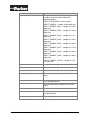
17.4. Obtaining Sampled, Filtered, and Converted
Data
The Input Manager samples, filters, and converts data.
There are three methods that can be used to obtain sampled, filtered, and
converted data with the input manager, as follows:
•
Refer to the data storage location for the input, as specified in the input
table.
•
Use the general service
o
•
input_get_value.
Use one of the specific services:
o input_get_raw_value,
o input_get_filtered_value
o input_get_converted_value
NOTICE
Refer to section 13.1 “Services” and its sub chapters for using the service
input_get_value.
17.4.1. Getting Input Data by Referring to a Data Storage Location
Referring to a data storage location is the most efficient way to obtain data using
the Input Manager.
NOTICE
In order to use this method, you must know the specific storage location for the
input.
To get input data by referring to a data storage location
•
Refer to the respective data storage location for the input, as specified in
the input table.
NOTICE
If an input is not configured to be sampled by the input manager, then just
referencing the respective data storage location is not sufficient, and a call to
input_get_value is required to force the required operation(s) to occur.
Example call:
The following example assumes an input table already exists, and that it is
configured to store the state of INPUT_1 in Din[0].
Copyright 2011-2015 © Parker-Hannifin Corporation. All rights reserved.
Page 90 of 114
if (*Din[0])
{
// INPUT_1 raw value is non-zero ...
}
17.4.2. Getting Input Data by Calling input_get_value
NOTICE
Using this method forces inputs set to INPUT_NO_SAMPLE to sample, filter, and convert
when input_get_value is called. To use this method, you do not need to know the
specific storage location for the input.
To get input data by calling input_get_value
•
Call Idata_ptr_t input_get_value(uint16 input, input_request_t
request); where
•
input is the index of the input within the input table (for example, 0 is
the first input, 1 is the second, etc.).
•
request
is the type of data request, where the following values apply:
is the raw value from the last sample.
•
INPUT_RAW
•
INPUT_FILTERED
•
INPUT_CONVERTED
•
INPUT_REALTIME_RAW
•
INPUT_REALTIME_FILTERED
•
is the filtered value from the last sample.
is the converted value from the last sample.
is the raw value after forcing a read.
is the filtered value after forcing a read.
INPUT_REALTIME_CONVERTED
is the converted value after forcing a
read.
Return Value: A pointer to the requested data where
•
NULL indicates the operation failed.
Example call:
hw_din_value_ptr_t input_1_value_ptr = input_get_value(INPUT_1,
INPUT_RAW);
if (*input_1_value_ptr)
{
// input on ...
}
17.4.3. Getting Input Data by Using a Specific Service
This section describes how to get the most recently sampled value of an input in
each of the following states:
•
Raw data (input_get_raw_value)
•
Filtered data (input_get_filtered_value)
Copyright 2011-2015 © Parker-Hannifin Corporation. All rights reserved.
Page 91 of 114
•
17.4.3.1.
Converted data (input_get_converted_value)
input_get_raw_value
This service is used to return raw input data.
To get the most recently sampled value of an input in its raw state
•
Call idata_ptr_t input_get_raw_value(uint16 input); where
•
input is the index of the input within the input table (for example, 0 is
the first input, 1 is the second, etc.).
Return Value: A pointer to the data requested where
•
NULL pointer indicates the operation failed.
Example of getting a raw state input value:
hw_din_value_ptr_t input_1_value_ptr = input_get_raw_value(INPUT_1);
if (*input_1_value_ptr)
{
// input raw state is non-zero (on) ...
}
17.4.3.2.
input_get_filtered_value
This service is used to return filtered input data.
To get the most recently sampled value of an input in its filtered state
•
Call idata_ptr_t input_get_filtered_value(uint16 input); where
•
input is the index of the input within the input table (for example, 0 is
the first input, 1 is the second, etc.).
Return Value: A pointer to the data requested where
•
NULL pointer indicates the operation failed.
Example of getting a filtered input value:
hw_din_value_ptr_t input_1_value_ptr = input_get_filtered_value(INPUT_1);
if (*input_1_value_ptr)
{
// input filtered state is non-zero (on) ...
}
17.4.3.3.
input_get_converted_value
This service is used to return converted input data.
Copyright 2011-2015 © Parker-Hannifin Corporation. All rights reserved.
Page 92 of 114
To get the most recently sampled value of an input in its converted state
Call idata_ptr_t input_get_ converted _value(uint16 input); where
•
•
input is the index of the input within the input table (for example, 0 is
the first input, 1 is the second, etc.).
Return Value: A pointer to the data requested where
NULL pointer indicates the operation failed.
•
Example of getting a converted input value:
hw_din_value_ptr_t input_1_value_ptr = input_get_ converted
_value(INPUT_1);
if (*input_1_value_ptr)
{
// input converted state is non-zero (on) ...
}
17.4.4. Commonly used read, filter and conversion services
17.4.4.1.
read_bit_uchar8
This service is for checking the state of one bit at the specified memory location.
The bit and address(port) are specified in the read parameters.
The state of the bit is stored in data_ptr as a 1 or 0.
To check the state of one bit in specified memory location:
Call void read_bit_uchar8 ( const idata_ptr_t
input_read_params_ptr_t params ) Where
•
data_ptr,
const
is a pointer to the state of the bit.
•
data_ptr
•
params are the read parameters including the specified address(port)
and bit (see read_bit_params_uchar8_t).
Return value: Nothing, but the result is stored in data_ptr
Example Call:
read_bit_uchar8(data_ptr, params);
if( *data_ptr )
{
// The state of the bit is 1.
}
17.4.4.2.
read_bit_uint16, read_bit_uint32
Checks the state of one bit at the specified memory location.The bit and
address(port) are specified in the read parameters. The state of the bit is stored
in data_ptr as a 1 or 0.
Copyright 2011-2015 © Parker-Hannifin Corporation. All rights reserved.
Page 93 of 114
To check the state of one bit in specified memory location:
Call void read_bit_uint16 ( const idata_ptr_t
input_read_params_ptr_t params )
Where
•
data_ptr,
const
is a pointer to the state of the bit.
•
data_ptr
•
params are the read parameters including the specified address(port)
and bit (see read_bit_params_uint16_t).
You may need to use read_bit_uint32 instead of read_bit_uint16. However,
the format is the same. Replace the function with desired type in your application
in such case. For params - see read_bit_params_uint32_t
Return value: Nothing, but the result is stored in data_ptr
Example Call - read_bit_uint16 used in here as example:
read_bit_uint16(data_ptr, params);
if( *data_ptr )
{
// The state of the bit is 1.
}
17.4.4.3.
read_buf_uchar8
This service copies the specified number of memory locations from the source to
the destination address. The source address and the number of locations to copy
are specified in the read parameters.
To copy memory locations:
•
Call void read_buf_uchar8 ( const idata_ptr_t
input_read_params_ptr_t params )
Where
•
data_ptr
•
params
data_ptr,
const
is a pointer to the destination address.
are the read parameters including the specified sourse
address and number of locations to copy (see
read_buf_params_uchar8_t).
Return value: Nothing, but the result is stored in data_ptr
Example Call:
read_buf_uchar8(data_ptr, params);
17.4.4.4.
read_buf_uint16, read_buf_uint32
This service copies the specified number of memory locations from the source to
the destination address. The source address and the number of locations to copy
are specified in the read parameters.
Copyright 2011-2015 © Parker-Hannifin Corporation. All rights reserved.
Page 94 of 114
To copy memory locations:
•
Call void read_buf_uint16 ( const idata_ptr_t
input_read_params_ptr_t params )
Where
•
data_ptr
•
params
data_ptr,
const
is a pointer to the destination address.
are the read parameters including the specified source
address and number of locations to copy (see
read_buf_params_uint16_t).
You may need to use read_buf_uint32 instead of read_buf_uint16. However,
the format is the same. Replace the function with desired type in your application
in such case. For params - see read_buf_params_uint32_t.
Return value: Nothing, but the result is stored in data_ptr
Example Call - read_buf_uint16 used in here as example:
read_buf_uint16(data_ptr, params);
17.4.4.5.
din_debounce_filter
Performs debounce filtering on a digital input.The debounce parameters are
specified in the filter paramters structure and includes the increment and
decrement steps, the upper and lower bounds where the result changes, the min
and max counts and a pointer to a counter where the current count is stored.
To perform debounce filtering for digital input
•
Call void din_debounce_filter ( const idata_ptr_t dst_data,
const idata_ptr_t
params )
where
src_data, const input_filter_params_ptr_t
•
dst_data If the
*dst_data to 1.
•
If the count has reached the lower change point - change *dst_data to
0.
src_data is the digital input to be debounce filtered.
params are the debounce parameters (see
din_debounce_filter_params_t).
•
•
count has reached the upper change point - change
Return Value: Nothing is returned but the result is stored in dst_data.
Example of debounce filtering
din_debounce_filter(dst_data, src_data, params);
filtering on *src_data.Returns
17.4.4.6.
// Performs debounce
running_average
This service performs a running average on an input. The parameters used for
averaging are specified in the filter parameters structure and the number of
samples to base the average on, an index that indicates the oldest sample, a
sum of the samples and a pointer to the samples.
Copyright 2011-2015 © Parker-Hannifin Corporation. All rights reserved.
Page 95 of 114
To get the running average on an input
•
Call void running_average ( const idata_ptr_t dst_data, const
idata_ptr_t src_data, const input_filter_params_ptr_t params)
where
•
•
•
dst_data is a pointer to the average value.
src_data is the input to run average on.
params are the parameters used for averaging
(see
running_average_params_t).
Return Value: Nothing is returned but the result is stored in dst_data.
Example call
running_average(dst_data, src_data, params);
// Stores the average value into dst_data.Returns
17.4.4.7.
convert_linear_sint32
This service performs linear conversion on an input in the form of y = mx/n + b.
The parameters are specified in the convert paramters structure and include
slope and intercept.
To perform a linear conversion on an input
•
Call void convert_linear_sint32 ( const idata_ptr_t dst_data,
const idata_ptr_t
where
params )
•
•
•
src_data, const input_convert_params_ptr_t
dst_data A pointer to the converted value.
src_data The input to performs linear conversion
params The parameters used for converting (see
convert_linear_params_t).
on.
Return Value: Nothing is returned but the result is stored in dst_data.
Example call
convert_linear_sint32(dst_data, src_data, params);
// Stores the converted value into dst_data.Returns
Copyright 2011-2015 © Parker-Hannifin Corporation. All rights reserved.
Page 96 of 114
18. FLASH
18.1. Overview
The flash module (pfw_flash.h) provides an interface for writing to and erasing
flash. File reference: pfw_flash.h ; stypes.h. Please refer to hw_config.h for details
about the platform's memory architecure for the flash_write(), flash_read() and
flash_erase_sector() function calls.
NOTICE
Refer to section 8.1 CM0711 Memory Map to clarify the available memory areas and
to chapter 8.2 Fixed Addresses for memory locations with static data.
18.2. Flash functions
This section provides you information how to:
-
Initialize the Flash memory void flash_init (void)
-
Write to Flash memory
-
Read from Flash memory uint16 flash_read (uint32 base_address,
uint32 offset, uchar8 *buffer, uint16 size)
-
Erase the Flash memory
boolean
base_address, uint32 sector)
uint16 flash_write (uint32 base_address,
uint32 offset, uchar8 *buffer, uint16 size)
flash_erase_sector (uint32
18.2.1. flash_init
Initialize internal and external flash memories. Call this once before using any
other flash functions.
To initialize the Flash -memory
•
Call void flash_init ( void
)
Return Value: Nothing
Example call
flash_init();
18.2.2. flash_write
Writes data to flash memory. Note there are some areas of flash that the
application may not be allowed to write to (such as the bootblock).
Copyright 2011-2015 © Parker-Hannifin Corporation. All rights reserved.
Page 97 of 114
To write to Flash - memory
•
Call uint16 flash_write ( uint32
uchar8 * buffer, uint16 size )
•
•
•
•
base_address, uint32
offset,
where
base_address is the start address of the section of flash to be
modified.
offset is the start address of memory that is written to is
"base_address + offset".
buffer is a pointer to the data to be programmed into the flash.
size is the number of bytes to be programmed into the flash.
Return Value: Is the number of bytes programmed sucessfully.
Example call
uint16 size_of_programmed_data;
size_of_programmed_data = flash_write(base_address, offset,
buffer_ptr, size);
18.2.3. flash_read
Reads data from flash memory.
To read from Flash - memory
•
Call uint16 flash_write ( uint32
uchar8 * buffer, uint16 size )
•
•
•
•
base_address, uint32
offset,
where
base_address is the start address of the section of flash to be read.
offset is the start address of memory that is read is "base_address +
offset".
buffer is a pointer to buffer where data is read.
size is the number of bytes to be read from the flash.
Return Value: Is the number of bytes read sucessfully.
Example call
uint16 size_of_read_data;
size_of_read_data = flash_read(base_address, offset, buffer_ptr,
size);
18.2.4. flash_erase_sector
Erases a flash sector. Note there are some areas of flash that the application may
not be allowed to erase (such as the bootblock).
To erase the Flash – memory sector
Copyright 2011-2015 © Parker-Hannifin Corporation. All rights reserved.
Page 98 of 114
Call boolean flash_erase_sector
sector ) where
•
•
•
( uint32
base_address Not used. For backwards
sector The sector to be erased.
base_address,
uint32
combatibility.
Return Value:
o
o
TRUE - success.
FALSE - failure.
Example call
if( TRUE == flash_erase_sector(base_address, sector))
{
// Successfully erases the flash sector.
}
Copyright 2011-2015 © Parker-Hannifin Corporation. All rights reserved.
Page 99 of 114
19. EEPROM Emulation
19.1. Overview
CM0711 Data Flash memory has hardware support for EEPROM emulation. This
feature allows you to read, write and delete data records without the need to
erase the memory. Emulation can be used for example to store calibration data or
user configurations. Frequent writing is not advised due to flash memory wearout.
This section provides you information how to:
-
Initialize the emulation.
-
Write records.
-
Read records.
-
Delete records.
19.2. Initialize the emulation
Emulation has 16368 bytes of effective memory space for storing records. Each
record takes up (16 + data length) bytes of memory rounded up to next 16 bytes.
So the minimum record size is 32 bytes and maximum number of such records is
511.
NOTICE
It is not recommended to use all available space as this will require more frequent
flash block swapping. Swapping is very expensive performance-wise and will corrupt
flash quickly if written frequently.
19.2.1. eeprom_init
Initializes EEPROM emulation system.
If necessary, creates or repairs the memory structures used for EEPROM emulation.
Fills the record data look-up table with pointers to valid records; null pointers are
written to look-up table for IDs that do not have a saved record.
Parameters
max_records
Maximum number of records in the look-up table (1 511).
Return value: char8
• EEPROM_OK: Init OK.
• EEPROM_FLASH_ERROR: Flash handling function returned an error,
couldn't finish initialization.
Example Call:
char8 err;
err = eeprom_init(100);
Copyright 2011-2015 © Parker-Hannifin Corporation. All rights reserved.
Page 100 of 114
19.3. Write Records
Writing is done in arbitrary size records. Each record will take space 16 bytes +
data size rounded up to next 16 bytes. So a record with a single char and a 16
byte string, both consume 32 bytes space.
A record with the same id can be written again without the need to delete it. Old
records are kept in the memory as long as there is free space left. The latest
record is set as active. You should always write the same type of data to a
specific record id. Or at least a type with the same size.
NOTICE
When space is eventually used up, the active emulation block is swapped and old
records are permanently erased. This can take several hundreds of milliseconds and
will wear out the flash memory. Therefore it is not recommended to use all space and
you should minimize write times.
19.3.1. eeprom_WriteRecord
Saves given data to non-volatile memory.
The new data replaces any existing data with the same record ID (look-up table is
updated). If necessary, flash block swap is performed during the write (in which case
look-up table pointers to all existing records are updated).
Parameters
record_id
data_length
*data
A label for identifying the stored data. Use values from
zero to (max_records - 1.
Number of data bytes in the record
Pointer to data that will be
written inside the record.
Return value: char8
• EEPROM_OK: Success.
• EEPROM_INVALID_PARAMETER: Too large value for record_id given or
null pointer specified for data.
• EEPROM_OUT_OF_MEMORY: EEPROM full or record is too big.
Example Call:
char8 err;
uint32 data = 123456789;
err = eeprom_WriteRecord(0, sizeof(uint32), &data);
Example Call:
char8 err;
some_struct_type data;
data.x = 10;
data.y = 20;
data.z = 30;
Copyright 2011-2015 © Parker-Hannifin Corporation. All rights reserved.
Page 101 of 114
err = eeprom_WriteRecord(1, sizeof(some_struct_type), &data);
19.4. Read Records
Read function returns a void pointer to the constant record data. Null pointer is
returned if data is not found.
19.4.1. eeprom_GetRecord
Retrieves pointer to an existing data record.
Parameters
record_id
Data identifier for the record.
Return value: void*
• NULL: Data not found.
• Pointer to data record. Cast to expected type.
Example Call:
const uint32* rec_ptr;
uint32 data;
rec_ptr = (const uint32*)eeprom_GetRecord(0);
if (rec_ptr)
{
data = *rec_ptr;
}
Example Call:
const some_struct_type* rec_ptr;
some_struct_type data;
rec_ptr = (const some_struct_type*)eeprom_GetRecord(1);
if (rec_ptr)
{
memcpy(&data, rec_ptr, sizeof(some_struct_type));
}
19.5. Delete Records
Delete function removes a single record without the need to erase the whole
block. It will also look for older references for the given record. If one is found, it is
restored and set as the active one.
19.5.1. eeprom_DeleteRecord
Deletes an existing data record and restores previous record of the same id, if any.
Call repeatedly to delete all references to a record.
Copyright 2011-2015 © Parker-Hannifin Corporation. All rights reserved.
Page 102 of 114
Parameters
record_id
Data identifier for the record.
Return value: char8
• EEPROM_OK: Record deleted.
• EEPROM_NO_DATA_FOUND: There is no saved record to delete.
• EEPROM_INVALID_PARAMETER: Too large value for record_id.
• EEPROM_FLASH_ERROR: Flash writing failed - system may be unstable
now!
Example Call:
char8 err;
err = eeprom_DeleteRecord(0);
Example Call:
char8 err;
do {
// Delete all references to record 1
err = eeprom_DeleteRecord(1);
while (err == EEPROM_OK);
Copyright 2011-2015 © Parker-Hannifin Corporation. All rights reserved.
Page 103 of 114
20. Cyclic Redundancy Check
The cyclic redundancy check (CRC) is an error-detecting code to detect accidental
changes to raw data. Short check value is attached to data blocks, based on the
remainder of a polynomial division of their contents. Calculation is repeated, while
the data is to be retrieved and evaluation can be made to see whether the retrieved
data is still usable.
20.1. Overview
The CRC module services in CM0711 SW Platform Framework provides a
functionality for calculating a 16-bit CRC on a block of data using the CRCCCITT Poly: 0xF0B8.
File Reference: pfw_crc.h
#include "stypes.h"
20.2. CRC Functions
There is 3 functions under this service
o
o
CRC Calculation
Inserting CRC
o
CRC result evaluation
NOTICE
CRC_NOT_COMPLIMENTED May have potential issues when the buffer size
changes and the new bytes are 0's.
CRC_COMPLIMENTED (Preferred to use this)
20.2.1.1.
crc16_calculation
Calculates a 16-bit CRC for the memory space pointed to by the data parameter
that is num_bytes in size.
To calculate CRC
•
uint16 crc16_calculation
)
where
•
•
( CRC_Void_Ptr
data, uint32
data is a pointer to the beginning of the data
num_bytes is the size of the data range.
Copyright 2011-2015 © Parker-Hannifin Corporation. All rights reserved.
num_bytes
range.
Page 104 of 114
Return Value: 16- bit CRC
Example Call:
crc = crc16_calculation(data_array, size_of_data);
20.2.1.2.
insert_crc
This function attach a 16-bit CRC to a data block. The routine will only calculate
the CRC on the (size-2) as the last 2 bytes are used to store the CRC (LSB first).
To Insert CRC:
•
Call boolean insert_crc ( CRC_Void_Ptr buffer, uint32
buffer_size, CRC_Complimented complimented )
where
buffer is a pointer to data buffer.
buffer_size is the size of data buffer.
complimented is the flag indicating if the
•
•
•
1's complimented CRC is to
be used.
Return Value:
• TRUE indicates success
• FALSE indicates failure
Example Call:
if (insert_crc(data_array, size_of_data, CRC_NOT_COMPLIMENTED))
{
// CRC is inserted sucessfully.
}Returns
TRUE;
}
20.2.1.3.
is_crc_ok
Checks a data block for a valid CRC. This assumes that the 16-bit CRC is in the
last 2 bytes of the data block in LSB first.
To evaluate CRC result
•
Call boolean is_crc_ok ( CRC_Void_Ptr buffer, uint32
buffer_size, CRC_Complimented complimented )
where
- refer to
•
data
•
Table 3: Parameters by Library for details.
•
•
•
buffer is a pointer to data buffer.
buffer_size is the size of buffer (including crc).
complimented is the flag indicating if the crc in
the buffer is the 1's
compliment.
Copyright 2011-2015 © Parker-Hannifin Corporation. All rights reserved.
Page 105 of 114
Return Value:
• TRUE indicates that CRC passes
• FALSE otherwise
Example Call:
if (is_crc_ok(data_array, size_of_data, CRC_NOT_COMPLIMENTED))
{
// CRC is ok.
}
Copyright 2011-2015 © Parker-Hannifin Corporation. All rights reserved.
Page 106 of 114
21. Application parameter table support
There are three functions in this service to provide means to ask version, build
and part number of application parameter table.
File references:
21.1.1.1.
•
hw_interface.h
•
hw_user.h
get_application_pararmeter_table_version
This function check the checksum and if it passes, it returns the application
parameter table version stored in specific memory address – see chapter 8.2
Fixed addresses for more information.
To check this info
•
Call uint16 get_application_pararmeter_table_version (void)
Return Value:
•
Application parameter table version information
•
Otherwise - returns 0xFFFF, when application parameter table version
information is not available
Example Call:
uint16 get_application_pararmeter_table_version( void )
{
uint16 version_number = 0xFFFF;
#ifdef INCLUDE_APPLICATION_PARAMETER_TABLE_SUPPORT
if (verify_application_parameter_table_checksum())
{
version_number = *Application_Parameter_Table_Version_Ptr;
}
#endif
return version_number;
}
21.1.1.2.
get_application_pararmeter_table_build_number
This function check the checksum and if it passes, it returns the application
parameter table build number –information stored in specific memory address –
see chapter 8.2 Fixed addresses for more information.
To check this info
Copyright 2011-2015 © Parker-Hannifin Corporation. All rights reserved.
Page 107 of 114
•
Call uchar8 get_application_pararmeter_table_build_number (void)
Return Value:
•
Application parameter table build number- information
•
Otherwise - returns 0xFF, when application parameter table build numberinformation is not available
Example Call:
uchar8 get_application_pararmeter_table_build_number( void )
{
uchar8 build_number = 0xFF;
#ifdef INCLUDE_APPLICATION_PARAMETER_TABLE_SUPPORT
if (verify_application_parameter_table_checksum())
{
build_number = *Application_Parameter_Table_Build_Number_Ptr;
}
#endif
return build_number;
}
21.1.1.3.
get_application_pararmeter_table_part_number
This function check the checksum and if it passes, it returns the application
parameter table part number –information stored in specific memory address –
see chapter 8.2 Fixed addresses for more information.
To check this info
•
Call uint32 get_application_pararmeter_table_part_number (void)
Return Value:
•
Application parameter table build number- information
•
Otherwise – returns 0xFFFFFFFF, when application parameter table build
number- information is not available
Example Call:
uint32 get_application_pararmeter_table_part_number( void )
{
uint32 part_number = 0xFFFFFFFF;
#ifdef INCLUDE_APPLICATION_PARAMETER_TABLE_SUPPORT
if (verify_application_parameter_table_checksum())
{
Copyright 2011-2015 © Parker-Hannifin Corporation. All rights reserved.
Page 108 of 114
part_number = *Application_Parameter_Table_Part_Number_Ptr;
}
#endif
return part_number;
}
Copyright 2011-2015 © Parker-Hannifin Corporation. All rights reserved.
Page 109 of 114
22. RAM
22.1. Overview
CM0711 RAM memory is divided into two blocks:
•
Stack
•
Program RAM memory
NOTICE
•
Refer to section 8.1 CM0711 Memory Map to clarify the available memory
areas.
There is reserved own block for the stack in RAM memory. With service
max_stack_usage application developer can determine stack usage. That service
is needed when checking the risk of overflowing the stack.
Header file(s) to include: stack_usage.h
All the rest operations using RAM memory will be placed on ‘program RAM
memory’ block. Also Heap Memory will be placed on that block in RAM. There is
one thing that application developer must be aware of CM0711 heap memory.
See section 22.3.
22.2. max_stack_usage
There is 1 service to get stack usage.
o
max_stack_usage
uint8 max_stack_usage(void)
To get stack usage percentage
•
Call uint8 max_stack_usage(void);
Return Value: Maximum percentage of available stack that has been in use at
some point since reset. Resolution 1=1%
Example Call:
uint8 usage_percentage;
usage_percentage = max_stack_usage();
Copyright 2011-2015 © Parker-Hannifin Corporation. All rights reserved.
Page 110 of 114
22.3. Heap memory requirement
NOTICE
CM0711 platform framework (pfw) requires approximately 300 bytes heap memory.
Application developer has to ensure that the heap is left with enough RAM.
Copyright 2011-2015 © Parker-Hannifin Corporation. All rights reserved.
Page 111 of 114
23. Module idTAG
This service is done to get CM0711 idTAG module id. The idTAG-resistor is
connected between CM0711 address pins (ADDR-H and ADDR-L). There are 8
possible idTAG module id:s from 0 to 7.
Refer to document: “CM0711_Instruction_HY33-4201-IBUK” for defined module
id-TAG resistor values. Other than specified values are interpreted as “0”.
Header file(s) to include: pfw_idTag.h
23.1. define_idTAG
There is 1 service to define cm0711 module id.
o
define_idTAG
To get resistor module id
Call uchar8 define_idTAG(uchar8 *valid_idTAG); where
•
*valid_idTAG; Retrieves the information if idTAG definition
succeed or failed (TRUE/FALSE).
Return Value: Address Id-Tag value 0..7
Example Call:
uchar8 valid;
uchar8 idTAG;
idTAG = define_idTAG(&valid);
23.2. Reading resistor like Analog Inputs
The idTAG-resistor can be read also with service used to read analog inputs.
Example read ad-value from ADDR_L pin with service get_realtime_ain_value:
hw_ain_value_t ad_value;
// idTAG resistor between ADDR_L & ADDR_H pins.
// Raw ad-value in ADDR_L analog input.
ad_value=get_realtime_ain_value((hw_ain_channel_t)ADDR_L, NULL);
Copyright 2011-2015 © Parker-Hannifin Corporation. All rights reserved.
Page 112 of 114
24. Frequently Asked Questions
Q: Can I access a JTAG port for software debugging purposes?
The CM0711 has JTAG port that is not accessible from outside its
enclosure in normal serial production units. However, it is
possible to order special development units from Parker.
Q: Can I develop PC applications for CM0711 communication using DLA?
Yes. The DLA supports RP1210 which is an industry standard. PC
applications can be written to interface via RP1210 to the DLA.
Reference Instruction book for USB-DLA on Parker website for
detailed information.
Q: I have shared variable between a thread and CAN rx table. Do I need to lock it
somehow?
No. Received data is passed from CAN rx interrupt to the
corresponding stack. The stack gets processed in an internal
thread. Since CM0711 does not support parallel threads, the
internal thread and your own thread cannot interrupt each other
and there is no conflict.
Q: Why isn’t there any main function in template project?
Main function is encapsulated inside the bootblock. It initializes
the system, invokes ap_init() and then enters main loop to
schedule running threads. That is why you need to fork at least
one thread in ap_init().
Copyright 2011-2015 © Parker-Hannifin Corporation. All rights reserved.
Page 113 of 114
25. Feedback
In order to ensure the manual meets your needs, we need your feedback. Please
answer the questions on this page and then fax the page to the Marketing
Services group at Parker Hannifin Manufacturing Finland Oy. Or, use the e-mail
address shown below to send us your comments.
Mailing address:
Parker Hannifin Manufacturing Finland Oy
P.O.Box 86,
FI-30101 Forssa
Finland
Fax:
+358 3 4335 157
E-mail:
info.ecdforssa@ parker.com
1. What is your comfort level with the subject matter?
Beginner — Intermediate — Advanced — Professional
2. How would you rate the quality of this manual?
1 (low) — 2 — 3 — 4 — 5 (high)
3. What do you like about this manual?
4. What do you dislike about this manual?
Copyright 2011-2015 © Parker-Hannifin Corporation. All rights reserved.
Page 114 of 114