1
GT Works Version5/GT Designer Version5
Reference Manual
SW5D5C-GTWORKS-E
SW5D5C-GOTR-PACKE(V)
MITSUBISHI Graphic Operation Terminal
• SAFETY PRECAUTIONS •
(Always read these instructions before using this equipment.)
Before using this product, please read this manual and the relevant manuals introduced in this manual
carefully and pay full attention to safety to handle the product correctly.
The instructions given in this manual are concerned with this product. For the safety instructions of the
programmable controller system, please read the CPU module user's manual.
In this manual, the safety instructions are ranked as "DANGER" and "CAUTION".
DANGER
Indicates that incorrect handling may cause hazardous conditions,
resulting in death or severe injury.
! CAUTION
Indicates that incorrect handling may cause hazardous conditions,
resulting in medium or slight personal injury or physical damage.
!
Note that the ! CAUTION level may lead to a serious consequence according to the circumstances.
Always follow the instructions of both levels because they are important to personal safety.
Please save this manual to make it accessible when required and always forward it to the end user.
[Test Operation Instructions]
!
DANGER
• Before performing test operation (bit device on/off, word device's present value changing,
timer/counter's set value and present value changing, buffer memory's present value changing)
for a user-created monitor screen, system monitoring, special module monitoring or ladder
monitoring, read the manual carefully to fully understand how to operate the equipment.
During test operation, never change the data of the devices which are used to perform
significant operation for the system.
False output or malfunction can cause an accident.
A-1
A-1
Precautions for using this software (important)
1. Memory of the personal computer used
Processing may be terminated by Microsoft Windows 95 operation system, Microsoft Windows 98
operation system, Microsoft Windows NT Workstation4.0 operation system,
Microsoft Windows Millennium Edition Operating system, Microsoft Windows 2000 Professional
Operating System on some personal computer models having main memory of not more than 32M bytes.
Therefore, use them after increasing the main memory to 32M bytes or more.
R
R
R
R
R
R
R
R
R
R
2. Free space on the hard disk
While this software is running, free space of at least 50M byte is required on the hard disk.
Since free space of 50M byte is required by Windows 95, Windows 98, Windows NT Workstation4.0,
Windows Me, Windows 2000 Professional as the swap area, Windows 95, Windows 98, Windows NT
Workstation4.0, Windows Me, Windows 2000 Professional may forcibly terminate the program if that free
space is used up while the drawing software is running. Produce a sufficient amount of free space on the
hard disk before using the drawing software. If you have to use the drawing software with an amount of free
space that is barely above the requirement, save project data as often as possible.
When GT Simulator is used with GX Developer or GX Simulator, free space is required separately.
Refer to the GX Developer or GX Simulator Operating Manual for the free space required for use of GX
Developer or GX Simulator.
R
R
R
R
R
R
R
R
R
R
3. Using a spin box in a dialog box
• Do not enter into a spin box a numerical value with a number of digits that drastically exceeds the maximum
number of digits that can be entered into the spin box. Entering a number of digits that drastically exceeds the
maximum allowable number of digits may cause a forcible termination of the program.
• On the [Action] tab selectable from the [Touch key] dialog box, the spin box provided for selecting a key
code does not display the key codes in the order of valid key codes when it displays the key codes for the
special keys used by such functions as the alarm history display, data list display, and alarm list (user
alarm) display. When you keep on clicking the button, therefore, the key codes will not be scrolled forward
or backward in the order of the valid key codes. (Clicking the button when the spin box displays "FFEF", for
example, will not display "FFB0" as the valid key code that comes next in the order.)
To specify such a key code for a special key associated with an object, use the keyboard the type the key
code into the spin box instead of making a selection from the spin box.
4. Operation on a table in a dialog box
To select a line on a table when specifying a object display range, for example, click on any part of the line
except the number display column. Clicking on the number display column on a line does not select the line.
If you clicked on the number display column on a line, that line is displayed in reverse video; click on the
number display column again to resume the display in normal video.
5. Instructions for displaying any line other than a continuous line (such as a dotted line) in boldface type
When any line other than a continuous line is drawn in boldface type, the personal computer screen may not
display the line type properly. However, it is displayed properly on the GOT and there are no problems in data.
6. Measures against the year 2000 (Y2K) problem
The GOT reads and displays the clock information from the PLC. When the GOT is connected to the
Mitsubishi PLC/Mitsubishi motion controller or is used with the A9GT-RS2T, continuous operation or restart
of the GOT will present no problem since the PLC/motion controller/A9GT-RS2T itself will perform 1999-to2000 roll-over operation and leap compensation properly. (No measures required) When connected to a
third party PLC, however, the GOT reads and displays the clock data from the third party PLC. Therefore,
contact the corresponding company for the clock data when the GOT is connected to the third party PLC.
7. About the messages displayed at start
"Internal error: null pointer access"
If the above error has appeared, change the setting in the following procedure.
1) Click the "Start" button, point to the [Settings]-[Control Panel] menu, and click.
2) Double-click the "Regional Settings" icon.
3) As the [Regional Settings Property] dialog box appears, choose "English". If the above message appears
with the setting of "English", choose the language other than English and restart the personal computer.
After a start, choose "English" again and restart the personal computer.
"Abnormal termination"
If the above error has appeared, check whether the hard disk has the free capacity of 50MB or more.
8. Printing (file save) on the Windows 2000
If save a lot of screen images at a time when performing "Save file" of the print function on the
Windows 2000, the bitmap file may not be saved correctly. In such cases, separate the screen images for
each and save it.
R
R
A-2
A-2
REVISIONS
* The manual number is given on the bottom left of the back cover.
Print Date
Aug., 2000
Oct., 2000
* Manual Number
SH (NA)-080117-A First edition
SH (NA)-080117-B Partial corrections
Section 2.1.2
Revision
Partial additions
Section 4.5.2, Section 2.2.3, Appendix7
Nov., 2000
SH (NA)-080117-C Partial corrections
Section 7.2.3
Partial additions
Section 4.3.1, Section 4.3.2, Section 4.5.2, Section 4.5.3, Section 5.2.1,
Section 5.2.2, Section 5.2.3, Section 5.3.3, Section 5.5, Section 5.6.1,
Section 5.6.2, Section 5.8, Section 7.1.2
Additions
Section 4.1.4, Section 4.1.5, Section 5.8.13, Section 5.8.14
Feb., 2001
SH (NA)-080117-D Partial corrections
Section 2.2.3, Section 4.1, Section 4.1.2, Section 4.3.1, Section 4.3.2,
Section 4.5.2, Section 5.1.4, Section 5.2.2, Section 5.5, Section 5.7,
Section 5.8.1, Section 5.8.5, Section 5.8.6, Section 5.8.7, Section 5.8.8,
Section 5.8.9, Section 5.8.10, Section 5.9.1, Section 6.5.2, Appendix5,
Appendix7
Partial additions
Section 3.2, Section 4.1.4, Section 4.5.3, Section 6.5, Section 6.6,
Section 6.7, Appendix4
Additions
Section 4.1.7
May, 2001
Jun., 2001
SH (NA)-080117-E Partial corrections
Section 3.2, Section.4.1.1, Section.4.1.2, Section.4.1.7, Section.4.2.2,
Section.4.3.1, Section.4.5.2, Section.4.5.3, Section.5.5.1, Section.5.2.1,
Section.5.3.1, Section.5.3.3, Section.5.5, Section.5.6.1, Section.5.8.1,
Section.5.8.2, Section.5.8.5, Section.5.8.12, Section.5.9.4, Section.6.5.2,
Section.7.1.2, Appendix1, Appendix2, Appendix3, Appendix7
SH (NA)-080117-F Partial corrections
Section 4.3.2, Section 5.1.4, Section 5.8.9, Appendix7
Additions
Section 5.9.5
Aug., 2001
May, 2002
SH (NA)-080117-G Partial corrections
Section 2.1.1, Section 2.1.2, Section 2.2.1, Section 2.2.2, Section 2.2.3,
Section 3.2, Section 4.4.2, Section 4.5.2, Section 5.2.1, Section 5.4.6,
Section 5.5, Section 5.8.4, Section 5.8.9, Section 5.9.2, Section 6.5.1,
Appendix6, Appendix 7
SH (NA)-080117-H Partial corrections
Section 2.2.3, Section 3.2, Section 4.1, Section 4.1.2, Section 4.1.4,
Section 4.1.5, Section 4.2.1, Section 4.2.2, Section 4.3.1, Section 4.3.2,
Section 4.5.1, Section 4.5.2, Section 5.1.4, Section 5.2.1, Section 5.2.2,
Section 5.3.3, Section 5.5, Section 5.8.13, Section 5.9.1, Section 5.9.2,
Section 6.5.1, Section 6.5.2, Appendix4, Appendix8
Additions
Appendix7
A-3
A-3
* The manual number is given on the bottom left of the back cover.
Print Date
Jul., 2003
* Manual Number
SH (NA)-080117-I
Revision
Partial corrections
Section 2.2.3, Section 3.1, Section 4.4.2, Section 4.5.3, Section 5.1.4,
Section 5.5, Section 5.9.1, Section 5.9.5, Section 7.2.2
Additions
Chapter 1, Appendix 8
Jan., 2004
Jun., 2004
SH (NA)-080117-J Partial corrections
Section 4.3.2, Section 4.5.1
SH (NA)-080117-K Partial corrections
Manuals
MODEL CODE change
Changed from 13JF95 to 1DM186
Oct., 2004
Jan., 2006
SH (NA)-080117-L Partial corrections
Precautions for using this software (important), Section 4.3.2,
Section 5.8.1, Section 7.1.2, Section 7.2.2, Section 7.2.3, Section 7.5.2
SH (NA)-080117-M Partial corrections
Section 4.5.2, Section 5.3.2, Section 5.4.1, Section 5.4.2, Section 5.4.5,
Section 5.8.1, Section 5.8.12, Section 5.9.5, Section 7.2.2
Additions
Section 3.7, Section 4.5.4
Japanese Manual Version SH-080112-N
This manual confers no industrial property rights or any rights of any other kind, nor does it confer any patent
licenses. Mitsubishi Electric Corporation cannot be held responsible for any problems involving industrial property
rights which may occur as a result of using the contents noted in this manual.
© 2000 MITSUBISHI ELECTRIC CORPORATION
A-4
A-4
INTRODUCTION
Thank you for choosing the Mitsubishi Graphic Operation Terminal.
Before using the equipment, please read this manual carefully to use the equipment to its optimum.
CONTENTS
SAFETY PRECAUTIONS...............................................................................................................................A- 1
Precautions for using this software (important)..............................................................................................A- 2
REVISIONS .....................................................................................................................................................A- 3
INTRODUCTION.............................................................................................................................................A- 5
CONTENTS.....................................................................................................................................................A- 5
About Manuals ................................................................................................................................................A- 9
Abbreviations and generic terms in this manual ...........................................................................................A-10
CHAPTER1 OVERVIEW
1- 1 to 1- 2
CHAPTER2 SYSTEM CONFIGURATION
2- 1 to 2- 5
2.1 System Configuration of Monitoring Screen ............................................................................................ 2- 1
2.1.1 System configuration....................................................................................................................... 2- 1
2.1.2 Operation environment.................................................................................................................... 2- 1
2.2 System Configuration of Data Transfer and Document Creation............................................................ 2- 2
2.2.1 System configuration....................................................................................................................... 2- 2
2.2.2 Compatible RS-232C cable ............................................................................................................ 2- 4
2.2.3 Compatible PC card (Only when the GOT-A900 series is used) .................................................. 2- 5
CHAPTER3 SCREEN CONFIGURATION OF GT DESIGNER
3- 1 to 3-21
3.1 Screen Configuration and Various Tools ................................................................................................. 3- 1
3.2 Menu Configuration................................................................................................................................... 3- 7
3.3 Basic Operation of Dialog Box................................................................................................................. 3-11
3.4 Operation of Template ............................................................................................................................. 3-13
3.5 Operation of Tool Palette......................................................................................................................... 3-16
3.6 How to Use Help ...................................................................................................................................... 3-18
3.6.1 Help menu makeup ........................................................................................................................ 3-19
3.6.2 Printing the help screen.................................................................................................................. 3-19
3.7 Contents of Help ...................................................................................................................................... 3-20
CHAPTER4 SPECIFICATION
4- 1 to 4-78
4.1 Types and Number of Screens Created................................................................................................... 4- 1
4.1.1 Base screen..................................................................................................................................... 4- 1
4.1.2 Window screen ................................................................................................................................ 4- 2
4.1.3 About the report screen.................................................................................................................. 4-10
4.1.4 Video window.................................................................................................................................. 4-11
4.1.5 RGB screen .................................................................................................................................... 4-21
4.1.6 Video window/RGB screen settings .............................................................................................. 4-23
4.1.7 Wide display screen ....................................................................................................................... 4-25
A-5
A-5
4.2 Drawing Figures and Number of Attributes............................................................................................. 4-27
4.2.1 Types of drawing figures ................................................................................................................ 4-27
4.2.2 Attribute type for selection.............................................................................................................. 4-29
4.2.3 Figures in bitmap file format........................................................................................................... 4-31
4.2.4 Character size by magnification..................................................................................................... 4-32
4.2.5 Data capacity of each figure........................................................................................................... 4-33
4.3 Types and Specifications of Available Object Functions ........................................................................ 4-34
4.3.1 Types of and restrictions on object functions for setting ............................................................... 4-34
4.3.2 Specifications of the object functions that may be set .................................................................. 4-37
4.4 Overlap Setting......................................................................................................................................... 4-45
4.4.1 Figure and object............................................................................................................................ 4-45
4.4.2 About overlapping Objects ............................................................................................................. 4-45
4.5 Available Devices..................................................................................................................................... 4-46
4.5.1 Internal devices of GOT ................................................................................................................. 4-46
4.5.2 Device ranges available for the GOT-A900 series........................................................................ 4-53
4.5.3 Device ranges available for the GOT-F900 series........................................................................ 4-69
4.5.4 Numeric Data that can be Handled with GOT............................................................................... 4-77
CHAPTER5 OBJECT FUNCTIONS
5- 1 to 5-140
5.1 Data Display Functions ............................................................................................................................. 5- 2
5.1.1 Numerical display function (shows word device data as a numerical value) ................................ 5- 2
5.1.2 Data list display function (lists multiple word device states as numerical values) ........................ 5- 5
5.1.3 ASCII display function (shows data stored consecutively within devices as a character string).. 5- 8
5.1.4 Clock display function (reads and shows clock data of PLC CPU) .............................................. 5-11
5.2 Message Display Functions..................................................................................................................... 5-14
5.2.1 Comment display function
(shows a comment corresponding to ON/OFF or value of monitor device) .......................................... 5-14
5.2.2 Alarm history display function
(shows a history of occurrence times, comments and others when a condition is enabled)................ 5-18
5.2.3 Alarm list display function (shows the error information of the system at error occurrence) ....... 5-24
5.3 Animation Display Functions ................................................................................................................... 5-27
5.3.1 Part display function (shows a part/screen corresponding to a device) ....................................... 5-27
5.3.2 Part movement display function (shows the movement of a part corresponding to a device) .... 5-30
5.3.3 Lamp display function (changes the lit-up color of a lamp with a device value) .......................... 5-33
5.3.4 Panelmeter display function (shows a meter according to a word device value) ........................ 5-36
5.4 Graph Display Functions ......................................................................................................................... 5-39
5.4.1 Trend graph display function (shows a word device value on trend graph)................................. 5-39
5.4.2 Line graph display function (shows word device values on line graph) ....................................... 5-46
5.4.3 Bar graph display function (shows word device values on bar graph) ......................................... 5-51
5.4.4 Statistical graph display function (shows word device values on statistical graph) ..................... 5-54
5.4.5 Scattered chart display function (shows word device values on scattered chart)........................ 5-57
5.4.6 Level display function (shows a word device value as a level)..................................................... 5-63
5.5 Touch Key Functions (When Touched, Touch Keys Perform such Functions as Device Value Change
and Screen Switching)............................................................................................................................. 5-66
5.6 Data Input Functions................................................................................................................................ 5-77
5.6.1 Numerical input function (writes any value to device)................................................................... 5-77
5.6.2 ASCII input function (writes any key code to word devices)......................................................... 5-81
A-6
A-6
5.7 Report Function (Prints Values Stored in Devices or Buffer Memory)................................................... 5-84
5.8 Other Object Functions ............................................................................................................................ 5-88
5.8.1 Hardcopy function (prints a monitor screen or converts it into image file) ................................... 5-88
5.8.2 System information function (confirms the GOT operating status on the PLC CPU) .................. 5-91
5.8.3 Observe status function (writes to the PLC CPU when the specified condition is enabled) ....... 5-94
5.8.4 Floating alarm function (causes comments to flow from right to left on a base screen).............. 5-98
5.8.5 Recipe function (reads/writes values in the specified device range).......................................... 5-100
5.8.6 Sound function (plays a sound on GOT) ..................................................................................... 5-104
5.8.7 Test function (changes the device value of the PLC CPU) ........................................................ 5-106
5.8.8 Barcode function (writes data read with barcode reader to PLC CPU)...................................... 5-107
5.8.9 Operation panel function (operates GOT externally) .................................................................. 5-108
5.8.10 Time action function (performs specified operation at preset time).......................................... 5-110
5.8.11 Sampling function (reads PLC CPU data under specified condition)....................................... 5-113
5.8.12 Script function (exercises display control under GOT program)............................................... 5-115
5.8.13 Video display function ................................................................................................................ 5-118
5.8.14 RGB screen function .................................................................................................................. 5-119
5.9 Useful Functions .................................................................................................................................... 5-120
5.9.1 Screen call function (reduces project data capacity) .................................................................. 5-120
5.9.2 Security function (limits users) ..................................................................................................... 5-127
5.9.3 Offset function (monitors multiple devices by setting of one device).......................................... 5-131
5.9.4 Expression function (performs operation processing of PLC CPU on GOT) ............................. 5-133
5.9.5 Station number switching function
(Switches the monitor destination to the same device of another station number) ................... 5-138
CHAPTER6 OPERATION FOR DISPLAY OF MONITORING SCREEN ON GOT
6- 1 to 6-12
6.1 Operations to Be Set for the First Time.................................................................................................... 6- 1
6.2 Operations for Drawing Figures................................................................................................................ 6- 2
6.3 Operations for Object Setting ................................................................................................................... 6- 2
6.4 Operations for Creating a Report Screen................................................................................................. 6- 3
6.5 Installation Operations of System Program ............................................................................................. 6- 4
6.5.1 Types of system program installed on GOT................................................................................... 6- 4
6.5.2 Required knowledge before installation of system program.......................................................... 6- 7
6.5.3 Installation of ROM_BIOS............................................................................................................... 6- 9
6.5.4 Installation of OS ............................................................................................................................ 6-10
6.6 Download of Screen Data........................................................................................................................ 6-11
6.7 Debugging of Screen Data ...................................................................................................................... 6-12
CHAPTER7 SCRIPT FUNCTIONS
7- 1 to 7-28
7.1 Overview.................................................................................................................................................... 7- 1
7.1.1 Features........................................................................................................................................... 7- 1
7.1.2 Operating instructions ..................................................................................................................... 7- 3
7.2 Specifications ............................................................................................................................................ 7- 6
7.2.1 Types ............................................................................................................................................... 7- 6
7.2.2 Control structure .............................................................................................................................. 7- 7
7.2.3 Usable data and representation methods ..................................................................................... 7-10
7.2.4 Script execution .............................................................................................................................. 7-14
A-7
A-7
7.3 Settings and Procedure for Execution..................................................................................................... 7-17
7.4 Program Examples .................................................................................................................................. 7-18
7.4.1 Touch keys with interlock function ................................................................................................. 7-18
7.4.2 Lamps which change their indications under multiple conditions................................................. 7-19
7.4.3 Password input screen with time limit function.............................................................................. 7-21
7.5 Troubleshooting ....................................................................................................................................... 7-23
7.5.1 Simulation on general C language compiler or debugger ............................................................ 7-23
7.5.2 Errors and corrective actions for script execution on GOT ........................................................... 7-25
APPENDICES
App- 1 to App-33
Appendix1 Operations for Use of the Conventional Model Data...............................................................App- 1
Appendix2 Display Speed of Object (Reference Value)............................................................................App- 5
Appendix3 List of Key Code .......................................................................................................................App- 7
Appendix4 Drawing Sheet .........................................................................................................................App-10
Appendix5 Printing Time of Hard Copy Function (Reference Value).......................................................App-16
Appendix6 Relationships between Extended Functions OS Installation and User Area
(Memory Map) .........................................................................................................................App-17
Appendix7 Synthesized Colors Available for XOR ...................................................................................App-18
Appendix8 List of Functions Added by Version Update of GT Works Version5
/ GT Designer Version5...........................................................................................................App-21
INDEX
A-8
Index- 1 to Index- 3
A-8
About Manuals
The following manuals are relevant to this product.
Refer to the following list and order the required manuals.
• Detailed manuals
Manual name
Manual number (Model code)
A985GOT/A975GOT/A970GOT/A960GOT User’s Manual
Explains the specifications, general system configuration, component devices, part names, option
unit loading methods, installation and wiring methods, maintenance and inspection methods, and
error codes of A985GOT/A975GOT/A970GOT/A960GOT unit.
(Available as option)
SH-4005
(1DM099)
A950GOT/A951GOT/A953GOT/A956GOT User’s Manual
Explains the specifications, general system configuration, component devices, part names, option
unit loading methods, installation and wiring methods, maintenance and inspection methods, and
error codes of A950GOT/A951GOT/A953GOT/A956GOT unit.
(Available as option)
SH-080018
(1DM103)
• Relevant Manual
For relevant manual, refer to the PDF manual stored within the drawing software.
A-9
A-9
Abbreviations and generic terms in this manual
Abbreviations, generic terms and special terms used in this manual are described as
follows:
Abbreviations, generic terms
and special terms
A985GOT-V
A985GOT
Description
Generic term of A985GOT-TBA-V and A985GOT-TBD-V
Generic term of A985GOT-TBA, A985GOT-TBD and A985GOT-TBA-EU
Generic term of A975GOT-TBA-B, A975GOT-TBD-B, A975GOT-TBA, A975GOT-TBD and
A975GOT
A975GOT-TBA-EU
Generic term of A970GOT-TBA-B A970GOT-TBD-B, A970GOT-TBA, A970GOT-TBD,
A970GOT
A970GOT-SBA, A970GOT-SBD, A970GOT-LBA, A970GOT-LBD, A970GOT-TBA-EU and
A970GOT-SBA-EU
A97*GOT
Generic term of A975GOT and A970GOT
A960GOT
Generic term of A960GOT-EBA, A960GOT-EBD and A960GOT-EBA-EU
Generic term of A956GOT-TBD, A956GOT-SBD, A956GOT-LBD, A956GOT-TBD-M3,
A956GOT
A956GOT-SBD-M3 and A956GOT-LBD-M3
A956WGOT
Generic term of A956WGOT-TBD
Generic term of A953GOT-TBD, A953GOT-SBD, A953GOT-LBD, A953GOT-TBD-M3,
A953GOT
A953GOT-SBD-M3 and A953GOT-LBD-M3
Generic term of A951GOT-TBD, A951GOT-SBD, A951GOT-LBD, A951GOT-TBD-M3,
A951GOT
A951GOT-SBD-M3 and A951GOT-LBD-M3
GOT
Generic term of A951GOT-QTBD, A951GOT-QSBD, A951GOT-QLBD, A951GOT-QTBD-M3,
A951GOT-Q
A951GOT-QSBD-M3 and A951GOT-QLBD-M3
Generic term of A950GOT-TBD, A950GOT-SBD, A950GOT-LBD, A950GOT-TBD-M3,
A950GOT
A950GOT-SBD-M3 and A950GOT-LBD-M3
Generic term of A950GOT-SBD-M3-H, A950GOT-SBD-M3-H, A953GOT-SBD-M3-H and
A950 handy GOT
A953GOT-LBD-M3-H
Generic term of A956GOT, A953GOT, A951GOT, A951GOT-Q, A950GOT and A950 handy
A95*GOT
GOT
F940GOT
Generic term of F940GOT-SWD-E, F940GOT-LWD-E, ET-940BH(-L) and ET-940PH(-L)
F930GOT
Generic term of F930GOT-BWD-E, F930GOT-BBD-K-E
F920GOT
Abbreviation of F920GOT-BBD5-K-E
Generic term of F940GOT-SBD-H, F940GOT-LBD-H, F943GOT-SBD-H, F943GOT-LBD-H,
F940 handy GOT
F940GOT-SBD-RH, F940GOT-LBD-RH, F943GOT-SBD-RH and F943GOT-LBD-RH
F940WGOT
Abbreviation of F940WGOT-TWD
Generic term of A985GOT-V, A985GOT, A975GOT, A970GOT, A960GOT, A95*GOT and
GOT-A900 series
GT SoftGOT
GOT-F900 series
Generic term of F940GOT, F930GOT, F920GOT, F940 handyGOT and F940WGOT
Generic term of A9GT-QBUSS, A9GT-QBUS2S, A9GT-BUSS and A9GT-BUS2S
Communica- Bus connection board
tion board
Serial communication board Generic term of A9GT-RS4, A9GT-RS2 and A9GT-RS2T
Generic term of A9GT-QBUS2SU, A9GT-BUS2SU, A9GT-BUS2SU, A7GT-BUSS and A7GTBus connection unit
BUS2S
Communica- Data link unit
Generic term of A7GT-J71AP23, A7GT-J71AR23 and A7GT-J71AT23B
tion unit
Network unit
Generic term of A7GT-J71LP23 and A7GT-J71BR13
CC-Link communication unit Generic term of A8GT-J61BT13 and A8GT-J61BT15
Abbreviation of A9GT-80PSC, A9GT-70PSC, A9GT-60PSC and A9GT-50PSC type
Protection sheet
transparent protection sheets
Abbreviation of A9GT-80LTT, A9GT-70LTTB, A9GT-70LTT, A9GT-70LTS and
Backlight
A9GT-50LT type backlights
Debug stand
Abbreviation of A9GT-80STAND, A9GT-70STAND and A9GT-50STAND type debug stand
PC card ( memory card )
Abbreviation of PC card with PCMCIA Ver.2.1
Flash PC card
Generic term of A9GTMEM-10MF, A9GTMEM-20MF and A9GTMEM-40MF
Option
Compact flash PC card
Compact flash PC card compliant with Compact FlashTM
Abbreviation
of A9GT-FNB, A9GT-FNB1M, A9GT-FNB2M, A9GT-FNB4M, A9GT-FNB8M,
Memory board
A9GT-QFNB, A9GT-QFNB4M, A9GT-QFNB8M type option function memory board
Attachment
Generic term of A77GT-96ATT/A85GT-95ATT/A87GT-96ATT/A87GT-97ATT attachments
Ten-key Panel
Abbreviation of A8GT-TK ten-key Panel
A7GT-CNB
Abbreviation of A7GT-CNB bus connector conversion box
A9GT-QCNB
Abbreviation of A9GT-QCNB bus connector conversion box
External I/O unit
Abbreviation of A9GT-70KBF and A8GT-50KBF type external I/O interface unit
Printer interface unit
Abbreviation of A9GT-50PRF type printer interface unit
Memory card interface unit
Abbreviation of A1SD59J-MIF memory card interface unit
Option unit
Video input interface unit
Abbreviation of A9GT-80V4 type Video input interface unit
RGB input interface unit
Abbreviation of A9GT-80R1 type RGB input interface unit
Video/RGB mixed input
Abbreviation of A9GT-80V4R1 type Video/RGB mixed input interface unit
interface unit
GT Works Version 5
Abbreviation of SW5D5C-GTWORKS-E software package
Generic term of SW5D5C-GOTR-PACKE software package and SW5D5C-GOTR-PACKEV
GT Designer Version 5
software package
Software
GT Designer
Abbreviation of image creation software GT Designer for GOT900
GT Simulator
Abbreviation of GT Simulator screen simulator GOT900
A - 10
A - 10
Abbreviations, generic terms and special terms
GT Converter
GT Debugger
GT Manager
Software
GT SoftGOT
GX Developer
GX Simulator
QCPU (Q Mode)
CPU
QCPU (A Mode)
QCPU
QnACPU (Large Type)
QnACPU (Small Type)
QnACPU
AnUCPU
AnACPU
AnNCPU
ACPU (Large Type)
A2US(H)CPU
AnS(H)CPU
A1SJ(H)CPU
ACPU (Small Type)
ACPU
FXCPU
Motion controller CPU
FA controller
Inverter
Peripheral
connection unit G4
Description
Abbreviation of data conversion software GT Converter for GOT900
Abbreviation of debugging software GT Debugger
Abbreviation of GT Manager data editing software for GOT900
Abbreviation of GT SoftGOT monitoring software
Generic term of SW D5C-GPPW-E/SW D5F-GPPW-E software packages
Generic term of SW D5C-LLT-E ladder logic test tool function software packages
(SW5D5C-LLT-E or later)
Generic term of Q00JCPU, Q00CPU, Q01CPU, Q02CPU, Q02HCPU, Q06HCPU, Q12HCPU,
Q25HCPU, Q12PHCPU and Q25PHCPU CPU units
Generic term of Q02CPU-A, Q02HCPU-A and Q06HCPU-A CPU units
Generic term of QCPU (Q Mode) and QCPU (A Mode)
Generic term of Q2ACPU, Q2ACPU-S1, Q3ACPU, Q4ACPU and Q4ARCPU CPU units
Generic term of Q2ASCPU, Q2ASCPU-S1, Q2ASHCPU and Q2ASHCPU-S1 CPU units
Generic term of QnACPU (Large Type) and QnACPU (Small Type)
Generic term of A2UCPU, A2UCPU-S1, A3UCPU and A4UCPU CPU units
Generic term of A2ACPU, A2ACPU-S1 and A3ACPU CPU units
Generic term of A1NCPU, A2NCPU, A2NCPU-S1 and A3NCPU CPU units
Generic term of AnUCPU, AnACPU and AnNCPU CPU units
Generic term of A2USCPU, A2USCPU-S1 and A2USHCPU-S1 CPU units
Generic term of A1SCPU, A1SHCPU, A2SCPU and A2SHCPU CPU units
Generic term of A1SJCPU-S3 and A1SJHCPU CPU units
Generic term of A2US(H)CPU, AnS(H)CPU and A1SJ(H)CPU CPU units
Generic term of ACPU (Large Type), ACPU (Small Type) and A1FXCPU CPU units
Generic term of FX0 series, FX0N series, FX0S series, FX1 series, FX1N series, FX1S series,
FX2 series , FX2C series, FX2N series, FX1NS series, FX2NC series, FX(2N)-10GM/20GM
series CPU unit
Generic term of A273UCPU, A273UHCPU, A273UHCPU-S3, A171SCPU-S3, A171SHCPU,
A172SHCPU, Q172CPU, Q173CPU CPU unit
Generic term of LM610, LM7600, LM8000 CPU unit
Generic term of FREQROL series (A500 Series, E500 Series, F500 Series)
Abbreviation of AJ65BT-G4-S3
Generic term of AJ71E71-S3, A1SJ71E71-B2-S3, A1SJ71E71-B5-S3, AJ71E71N-B2,
AJ71E71N-B5T, A1SJ71E71N-B2 and A1SJ71E71N-B5T
Generic term of AJ71QE71, A1SJ71QE71-B2, AJ71QE71-B5, A1SJ71QE71-B5,
QE71
AJ71QE71N-B2, AJ71QE71N-B5T, A1SJ71QE71N-B2 and A1SJ71QE71N-B5T
Q series-compatible E71
Generic term of QJ71E71, QJ71E71-B2 and QJ71E71-100
Generic term of C200HS, C200H, C200H series(C200HX, C200HG, C200HE), CQM1,
Omron PLC
C1000H,C2000H,CV500, CV1000, CV2000, CVM1-CPU11, CVM1-CPU21, CS1, CJ1 CPU unit
Generic term of GL60S, GL60H, GL70H, GL120, GL130, CP-9200SH, CP-9300MS, MP-920,
Yasukawa PLC
MP-930, MP-940, CP-9200(H) and PROGIC-8 CPU unit
SLC500 Series
Generic term of SLC500-20, SLC500-30, SLC500-40, SLC5/01 SLC5/02, SLC5/03, SLC5/04 SLC5/05
Generic term of 1761-L10BWA, 1761-L10BWB, 1761-L16AWA, 1761-L16BWA, 1761MicroLogix1000 Series
L16BWB, 1761-L16BBB, 1761-L32AWA, 1761-L32BWA, 1761-L32BWB, 1761-L32BBB,
1761-L32AAA, 1761-L20AWA-5A, 1761-L20BWA-5A, 1761-L20BWB-5A
MicroLogix1500 Series
Abbreviation of 1764-LSP
Allen-Bradley PLC
Generic term of SLC 500 Series, MicroLogix1000 Series, MicroLogix1200 Series, MicroLogix1500 Series
Generic term of JW-21CU, JW-22CU, JW-31CUH, JW-32CUH, JW-33CUH, JW-50CUH,
Sharp PLC
JW-70CUH, JW-100CUH CPU unit
PROSEC T Series
Generic term of T2 (PU224 type), T2E, T2N, T3, T3H CPU unit
PROSEC V Series
Abbreviation of Model3000 (S3) CPU unit
Toshiba PLC
Generic term of PROSEC T Series and PROSEC V Series
SIEMENS PLC
Generic term of SIMATIC S7-200 Series, SIMATIC S7-300 Series and SIMATIC S7-400 Series CPU unit
Generic term of H-302(CPU2-03H), H-702(CPU2-07H), H-1002(CPU2-10H), H-2002(CPU2Large type H series
20H), H-4010(CPU3-40H),.J-300(CPU-03Ha), H-700(CPU-07Ha), H-2000(CPU-20Ha)
Generic term of H-200(CPU-02H, CPE-02H), H-250(CPU21-02H), H-252(CPU22-02H), HH200 to 252 Series
252B(CPU22-02HB), H-252C(CPU22-02HC, CPE22-02HC)
Generic term of H-20DR, H-28DR, H-40DR, H-64DR, H-20DT, H-28DT, H-40DT, H-64DT,
H Series board type
HL-40DR, HL-64DR
EH-150 Series
Generic term of EH-CPU104, EH-CPU208, EH-CPU308, EH-CPU316
HITACHI PLC (HIDIC H Series) Generic term of large type H series,H-200 to 252 Series H Series board type, EH-150 Series
Matsushita Electric Works Generic term of FP0-C16CT, FP0-C32CT, FP1-C24C, FP1-C40C, FP2, FP2SH, FP2-CCU,
PLC
FP3, FP5, FP10(S), FP10SH, FP-M(C20TC) and FP-M(C32TC)
Memory
abbreviation of memory (flash memory) in the GOT
OS
Abbreviation of GOT system software
Object
Setting data for dynamic image
Personal Computer
Personal computer where the corresponding software package is installed
Servo amplifier
Generic term of MR-J2S- A, MR-J2S- CP and MR-J2M A series
E71
Ethernet unit
Other PLC
Others
In this manual, the following products are called by new names.
Old Name
GPPW
A - 11
New Name
GX Developer
Remarks
Generic term of SW D5C-GPPW-E/SW D5F-GPPW-E software packages
A - 11
1 OVERVIEW
MELSOFT
CHAPTER1 OVERVIEW
1
This manual describes the system configuration, screen makeup, basic dialog box
operation methods, specifications, help using methods, functions and others of the
following products used with the GOT900 series.
• SW5D5C-GTWORKS-E software package
• SW5D5C-GOTR-PACKE software package
• SW5D5C-GOTR-PACKEV software package
Exclusive updating products which can be utilized by those who use the previous
products.
In this manual, the above products are abbreviated to the following.
SW5D5C-GTWORKS-E ...........................................................GT Works Version5
SW5D5C-GOTR-PACKE/SW5D5C-GOTR-PACKEV.............GT Designer Version5
POINT
• This manual describes only the basic operation methods, specifications and
functions.
Refer to the help of the corresponding software package for information on
setting details and operation methods (e.g. figure drawing for monitor screen
creation, object function setting operation, data transfer to the GOT).
Refer to Chapter 5 for how to use help.
• GT Works Version5 and GT Designer Version5 do not support the functions
added to GT Designer2.
When it is desired to use the functions added to GT Designer2, consider using
GT Designer2.
1-1
1-1
1 OVERVIEW
MELSOFT
MEMO
1
1-2
1-2
2 SYSTEM CONFIGURATION
MELSOFT
CHAPTER2 SYSTEM CONFIGURATION
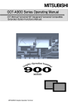
2.1 System Configuration of Monitoring Screen
2.1.1 System configuration
2
GT Works Version5
GT Designer Version5
IBM PC/AT or 100% compatible
2.1.2 Operation environment
Item
Description
Pentium
133MHz or higher (Pentium II
R
Personal computer on which Microsoft
Body
Windows
R
R
266MHz or higher recommended)
Windows
98 operating system, Microsoft
system operates, Microsoft
Microsoft
R
R
Windows
R
Windows
R
R
R
R
95 operating system, Microsoft
WindowsNT
R
R
Workstation 4.0 operating
Millennium Edition Operating System or
2000 Professional Operating System.
Disk drive
CD-ROM drive is mandatory.
Main memory
32 Mbyte (64 Mbyte or more is recommended.)
At the time of complete installation
Hard disk space
When installed
: 80M bytes or more
When operating
CRT
: 50M bytes or more
Compatible with Windows
Windows
R
R
95, Windows
R
98, WindowsNT
R
4.0, Windows
R
Me,
2000 Professional
Display colors
256 colors
Resolution
Resolution of 800 × 600 dots or more
Mouse, keyboard, printer,
Compatible with Microsoft
CD-ROM drive
Me, Windows
R
R
Windows
R
95, Windows
R
98, WindowsNT
R
4.0, Windows
R
2000 Professional
POINT
Depending on the language of your Operating System, this software may not start.
In such a case, start this software after setting the Regional Settings within Control
Panel of Windows 95, Windows 98, WindowsNT 4.0 to "English".
R
2-1
R
R
2-1
2 SYSTEM CONFIGURATION
MELSOFT
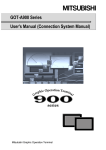
2.2 System Configuration of Data Transfer and Document Creation
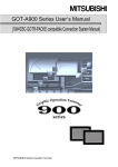
2.2.1 System configuration
(1) When the GOT-A900 is used
2
1
GOT-A900 Series
RS-232C cable
IBM PC/AT or 100% compatible
2
OS program and monitoring screen data
can be transferred (written) on the
PC card.
PC card with PCMCIA
Ver. 2.1
GT Works Version5
GT Designer Version5
Printer cable
Windows R compatible printer
1: Refer to Item 2.2.2 for wiring diagram of RS-232C.
2: Refer to Item 2.2.3 for available PC cards.
2-2
2-2
2 SYSTEM CONFIGURATION
MELSOFT
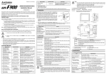
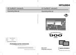
(2) When the GOT-F900 series is used
1
RS-232C cable
GOT-F900 series
IBM PC/AT or 100% compatible
Printer cable
Windows R compatible printer
GT Works Version5
GT Designer Version5
1: Refer to Item 2.2.2 for wiring diagram of RS-232C.
2-3
2-3
2 SYSTEM CONFIGURATION
MELSOFT
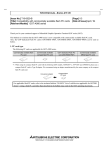
2.2.2 Compatible RS-232C cable
The cable in the wiring diagram below or the cable type below is required.
POINT
When the cable is self-made for the GOT-A900 series/GOT-F900 series, either of
the following wiring diagrams (1) and (2) may be used.
However, if the F940GOT/F930GOT is connected to the A series CPU or the FX
series CPU with RS422 to use the PLC CPU and the GOT with the FX-2PIF at the
same time, use the F2-232CAB-1 connection cable.
(1) Wiring diagram of AC30R2-9SS
IBM PC/AT or 100% compatible
RXD
2
3
TXD
7
RTS
8
CTS
6
DSR
SG
5
4
DTR
GOT
2
3
7
8
6
5
4
RXD
TXD
RTS
CTS
DSR
SG
DTR
Shield
(2) Wiring diagram of FX-232CAB-1
IBM PC/AT or 100% compatible
RXD
2
TXD
3
RTS
7
CTS
8
DSR
6
SG
5
DTR
4
GOT
2
3
7
8
6
5
4
RXD
TXD
RTS
CTS
DSR
SG
DTR
Shield
Use the screw-in type connector (inch) for the GOT side.
IBM PC/AT
or
100% compatible
Manufacturer
Mitsubishi Electric
AC30R2-9SS
FX-232CAB-1
GOT
Type
AC30R2-9SS (9pin-9pin)
FX-232CAB-1 (9pin-9pin)
If the following cable is used, 9-25 pin converter is required.
Manufacturer
Mitsubishi Electric
2-4
Type
AC30R2-9P (9pin-25pin)
F2-232CAB-1 (9pin-25pin)
2-4
2 SYSTEM CONFIGURATION
MELSOFT
2.2.3 Compatible PC card (Only when the GOT-A900 series is used)
(1) About compatible PC card types
For the PC cards available for the GOT, refer to the User's Manual supplied with
the GOT unit.
(2) About PC card formatting
Use the PC card after formatting.
It may be formatted in either of the following ways.
(a) Using the personal computer (SRAM type, flash PC card)
Format the PC card on the personal computer that satisfies the following
conditions.
1) The PCMCIA card slot is provided.
2) Windows 95, Windows 98, Windows Me or Windows 2000 has been
installed.
(Note that Windows NT 4.0 cannot format the PC card.)
R
R
R
R
R
POINT
• The PC card used with the GOT should be formatted in either of the following
systems.
• SRAM type PC card : FAT16
• Flash PC card
: FAT16, FAT32
• To make the SRAM type PC card recognized by Windows 95 or Windows 98,
config.sys must be added to the description.
For details, enter "SRAM" and keyword in Help of Windows 95 or Windows 98,
and refer to the contents.
R
R
R
R
(b) Using the self-diagnostics (memory card check) of the utility
menu
This method is valid for the SRAM type PC card only.
This method is fewer in the number of object files that may be saved than
the method using the personal computer.
For details of the utility menu, refer to the GOT-A900 Series Operating
Manual (GT Works Version5/GT Designer Version5 Compatible Extended •
Option Functions).
(3) About the number of files that may be saved
There are the following upper limits to the number of object files that may be
saved according to the memory capacity of the PC card.
Number of Files
Total of recipe, alarm history and
Total of all files 1
report files
Max. 2025 files
1M
(512 bytes/file)
Max. 128 files
Max. 4075 files
2M
(512 bytes/file)
Max.
2041 files
4M
Max. 256 files
(2048 bytes/file)
Max. 2541 files
16M (A9GTMEM-10MF)
(4096 bytes/file)
Max. 9740 files
32M (A9GTMEM-20MF)
Max. 512 files
(2048 bytes/file)
Max. 19497 files
48M (A9GTMEM-40MF)
(2048 bytes/file)
Memory Capacity of PC
Card
1: Indicates the maximum number of files that can be stored when the file size is as
indicated in the parentheses.
For example, when data of 3072 bytes is written to the above 4M PC card, the data
occupies two files and are stored there since the data exceeds the parenthesized
value (2048).
As a result, the remaining number of files where data can be written is 2039.
2-5
2-5
3 SCREEN CONFIGURATION OF GT DESIGNER
MELSOFT
CHAPTER3 SCREEN CONFIGURATION OF GT DESIGNER
3.1 Screen Configuration and Various Tools
This section describes screen configuration and various tools.
(1) Title bar
(2) Menu bar
(12) Help
(4) Toolbar (Main)
(5) Toolbar (View)
(6) Toolbar
(Figure . Object)
(7) Toolbar (Edit)
(1) Title bar
(10) Template
(11) Tool palette
(8) Toolbar (Draw)
(9) Status bar
(3) Drop-down menu
3-1
3-1
3
3 SCREEN CONFIGURATION OF GT DESIGNER
MELSOFT
(1) Title bar
The screen title is displayed.
Move the cursor to the title bar. You can drag the screen to the desired position.
The GT Designer has the application window title bar and the screen title bar.
The title is displayed.
The screen size can be changed or the
screen can be closed.
The screen enlarges or shrinks.
The screen can be minimized.
Click here to close
the screen.
3
(2) Menu bar
Menu names that can be used on the GT Designer are displayed.
Select a menu and a dropdown menu appears. Then, various functions can be
selected from this menu.
(3) Dropdown menu
Function names that can be used on the GT Designer are displayed.
If " " is displayed at the right end of the dropdown menu, subsequent dropdown
menu of the function is displayed.
If "..." is displayed on the function name, move the cursor to the function and click
it. The set dialog box appears.
Dropdown menu
is displayed.
Select this and the
dialog box appears.
3-2
3-2
3 SCREEN CONFIGURATION OF GT DESIGNER
MELSOFT
(4) Toolbar (Main)
This is where the basic items assigned on the menu bar appear as buttons. Move
the cursor onto any tool button and click it to perform the corresponding function.
1) 2) 3)
4) 5) 6)
7) 8) 9)
10)
11)
Names of tool buttons
1) New project
2) Open project
3) Save project
4) New screen
5) Load screen
6) Save screen
7) Cut
8) Copy
9) Paste
10) Preview
12) 13) 14) 15) 16) 17)
18) 19) 20)
11) Switching edit screen
12) Open and display closed screen (for
switching edit screen)
13) Object list screen display
14) Device list screen display
15) Comment edit
16) Tool palette display
17) Template display
18) Panelkit display
19) Figure and object editing cursor
20) Template placing cursor
(5) Toolbar (View)
This is where the items (moving distance, pattern, etc.) assigned on the menu
bar appear as buttons.
Moving the cursor onto " " and clicking it opens the drop-down menu of the
corresponding item.
Move the cursor to the attribute you want to change and click it to perform the
corresponding function.
1)
2)
3)
4)
5)
6)
7)
1) Setting cursor moving distance
2) Enlarging screen
3) Setting grid color
4) Grid distance
5) Switching ON/OFF object functions
3-3
8)
9)
10)
6) Setting screen display data (object
ID, device)
7) Setting screen color
8) Setting screen pattern
9) Setting screen background
10) Switching screen-drawn target
(GOT-F900 series only)
3-3
3 SCREEN CONFIGURATION OF GT DESIGNER
MELSOFT
POINT
When a pattern is set to the background of the screen using "Pattern (8))", the set
pattern is not deleted completely if "Pattern (8))" is set to "No" again.
The outer frame of the screen is displayed in the color set to Color (7)).
(The outer frame is not displayed when Color (7)) is set to Black (0).)
When it is desired to delete the pattern settings, display the [Screen Auxiliary
Setting] dialog box of the screen where the pattern has been set, and remove the
checkmark in the "Sheet color" checkbox.
Screen Auxiliary Setting Dialog Box
The details of the "Screen Auxiliary Setting" dialog box settings and operation
information can be browsed by choosing the following Help items.
(1) Choose [Help] - [Object setting].
(2) Choose "Operations after making screen" "Defining the input processing
specifications for each screen" in the Help contents.
(6) Toolbar (Figure • Object)
This is where the figure/object setting items laid out in the tool palette appear as
buttons.
Move the cursor onto any tool button and click it to perform the corresponding
function.
1) 2) 3) 4) 5) 6) 7) 8) 9) 10) 11) 12)
13) 14) 15) 16) 17) 18) 19) 20) 21) 22) 23) 24) 25) 26) 27) 28) 29) 30)
Names of tool buttons
1) Line
2) Line freedom
3) Rectangle
4) Polygon
5) Circle
6) Arc
7) Sector
8) Scale
9) Text
10) Paint
11) Insert BMP format file
12) Insert DXF format file
13) Numerical display function
14) Data list display function
15) ASCII display function
3-4
16) Clock display function
17) Comment display function
18) Alarm history display function
19) Alarm list display function
20) Part display function
21) Part movement display function
22) Lamp display function
23) Panel meter display function
24) Line/trend/bar graph display function
25) Statistics graph display function
26) Scatter chart display function
27) Level display function
28) Touch key function
29) Numerical input function
30) ASCII input function
3-4
3 SCREEN CONFIGURATION OF GT DESIGNER
MELSOFT
(7) Toolbar (Edit)
This is where the figure editing items assigned on the menu bar appear as
buttons.
Move the cursor onto any tool button and click it to perform the corresponding
function.
1) 2) 3) 4) 5) 6) 7) 8) 9)
10) 11) 12) 13)
Names of tool buttons
1) Bring to front
2) Send to back
3) Grouping
4) Canceling grouping
5) Horizontal flip
6) Vertical flip
7) 90° counterclockwise
8) Edit vertex
9) Align
10) Selection target (figure)
14) 15) 16) 17) 18) 19)
11) Selection target (object)
12) Selection target (figure+object)
13) Selection target (report line)
14) Report figure (line)
15) Report figure (text)
16) Report print object (numerical)
17) Report print object (comment)
18) Setting report header line
19) Setting report repeat line
(8) Toolbar (Draw)
This is where the items (line style, pattern, text style, etc.) laid out in the tool
palette appear as lists.
Moving the cursor " " onto any button and clicking it opens the drop-down menu
of the corresponding item.
Move the cursor to the attribute you want to change and click it to perform the
corresponding function.
1)
2)
3)
4)
5)
1) Set/change of line style
2) Set/change of line width
3) Set/change of line color
4) Set/change of painting pattern
5) Set/change of painting color
6)
7)
8)
9)
6) Set/change of painting background
color
7) Set/change of character color
8) Set/change of character decoration
9) Set/change of character shade color
(9) Status bar
This is where the current operation status and cursor coordinates are displayed.
Current operation status is displayed.
Cursor coordinates
are displayed.
(10) Template
This is provided to register and read the panelkit and parts easily.
Refer to Section 3.4 for details.
3-5
3-5
3 SCREEN CONFIGURATION OF GT DESIGNER
MELSOFT
(11) Tool palette
This is where the buttons for setting figures, objects and so on are displayed.
Refer to Section 3.5 for details.
(12) Help
This is where how to operate GT Designer, how to create/edit the GOT screen
data, and other information are shown.
Refer to Section 3.6 for details.
3-6
3-6
3 SCREEN CONFIGURATION OF GT DESIGNER
MELSOFT
3.2 Menu Configuration
This section describes the command list allocated on the menu bar and explains the
details.
(1) GT Designer
Project
Edit
New
Open
Close
Save
Save as
Import File
Project
Bitmap
Dxf
GPP Comment
Print
Option
Exit
Undo
Cut
Copy
Paste
Consecutive Copy
Delete
Edit Vertex
Object of Selection
Figure
Object
Figure and Object
Report line
Select All
Group
Group
Switch group
Ungroup
Rotate/Flip
Flip Vertical
Flip Horizontal
Rotate Left
Align
Stacking Order
Bring to Front
Send to Back
Attribute
Replace Devics
Replace Overlap Screen
View
Preview
ON Image
Redisplay
Color Setting
Device List
Screen
Project
Object List
Overlap Screen
Option
3-7
New project data is created.
Existing file is read.
Editing file is closed.
Editing file is saved with project data.
Editing file is saved as different name and editing continues.
Other project data is used for the project data in editing.
BMP format figure data is pasted on the screen.
DXF format figure data is pasted on the screen.
GX Developer device comment file to be read into the GT Designer is specified.
Setting data and screen image is output to printer and files.
Operation, display and communication environments are set.
GT Designer is ended.
The last operation for the data is cancelled and the previous data is maintained.
Figures and objects are cut and stored in the clipboard.
Selected figures, characters and objects are stored in the clipboard.
Figures and objects stored in the clipboard are pasted.
Selected figures and objects are copied and pasted on the multiple editing screen.
Selected figures and objects are deleted.
Length of continuous line or lines designated by polygon is changed.
Only figures are edited.
Only objects are edited.
Figures and objects are edited.
Report lines are edited.
All figures and objects are selected.
Selected figures and objects are grouped.
Grouping of selected objects as a single object.
Grouping of selected figures and objects is canceled.
Selected figures are flipped vertically.
Selected figures are flipped horizontally.
Selected figures are rotated to the left by 90°.
Selected figures and objects are aligned.
Selected figures and objects are brought to front.
Selected figures and objects are sent to back.
Attributes of selected figures and objects are changed.
The set monitoring devices are replaced with other devices.
Overlap screen numbers are batch-changed.
Screen details are displayed in monitoring image.
Screen details are displayed in ON.
Editing screen is re-displayed.
16 colors that are displayed on the color list are selected.
Displays the device list used for each screen.
Displays the device list used for each project.
Object list set in the screen is displayed.
Overlap screens are displayed hierarchically.
Operation, display and communication environments are set.
3-7
3 SCREEN CONFIGURATION OF GT DESIGNER
Draw
Panelkit
Part
Comment
Draw Figure
Line
Line Freeform
Rectangle
Polygon
Circle
Arc/Sector
Scale
Text
Paint
Data Display
Numerical Display
Data List
Ascii Display
Clock
Message Display
Comment
Alarm History
Alarm List
Animation Display
Part Display
Part Movement
Part Move Route
Lamp
Panelmeter
Graph
Trend/Line/Bar
Report
Reads, registers and deletes the panel kit.
Registers the part for the part display function and the part movement function.
Registers the comment for the comment display function, the alarm list display function
and the alarm history display function.
Draws linear line.
Draws a continuous linear line.
Draws a rectangle.
Draws a polygon.
Draws a circle.
Draws an arc/sector.
Draws graduation.
Inputs characters.
Paints a polygon or a closed area with selected pattern.
Sets the numerical display function.
Sets the data list display function.
Sets the ASCII display function.
Sets the clock display function.
Sets the comment display function.
Sets the alarm history display function.
Sets the alarm list display function.
Sets the part display function.
Sets the part movement function.
Sets the part movement route.
Sets the lamp display function.
Sets the panel meter function.
Sets the trend graph display function, the line graph display function and the bar graph
display function.
Sets the statistical graph function.
Sets the scatter chart display function.
Sets the level function.
Sets the touch key function.
Statistics
Scatter chart
Level
Touch Key
Data Input
Numerical Input
Ascii Input
Overlap Screen
Window Position
Overlap Window 1
Overlap Window 2
Superimpose Window
Key Window
Sets the window screen position for overlap window 1.
Sets the window screen position for overlap window 2.
Sets the window screen position for superimpose window.
Sets the key window position.
Key Window Custom
Input Value Area
Input Range Area
Sets the input value display area in the key window.
Sets the input range display area in the key window.
Common
Parameter
Print Object
Number
Comment
Line
Text
Header/Continue
3-8
MELSOFT
Sets the numerical input function.
Sets the ASCII input function.
Sets the overlap screen function.
Makes settings for the whole report function.
Sets the parameters of each report screen.
Sets the value to be printed.
Sets the comment to be printed.
Draws the rules (rectangle).
Enters characters.
Specifies the header and repeated lines.
3-8
3 SCREEN CONFIGURATION OF GT DESIGNER
Communication
Common
MELSOFT
Download (to GOT)
Monitor Data
Special Function/
Motion/Servo
amplifier Monitor Data
Upload (from GOT)
Install
Downloads the created monitoring screen data to the GOT or the PC card.
Downloads the special Function monitoring data/Motion Monitor data/
Servo amplifier data to the GOT or the PC card.
OS
ROM_BIOS
Memory
Data Check
Option
Installs the OS on the GOT or the PC card.
Installs the ROM_BIOS on the GOT or the PC card.
Displays or clears the memory.
Checks the number of monitoring data.
Operation, display and communication environments are set.
Uploads the monitoring data stored in the GOT.
Title
Screen
Project
Switching Screen
Switching Station No.
Ethernet
Gateway
Sets the titles and details for each base screen, window screen and report screen.
Registers the title and the ID number of the project data.
Sets the base/window screen switching device.
Sets the station No. switching device.
Sets the monitor destination for Ethernet connection.
Server
Client
Mail
FTP Server
Password
Hardcopy
Operation Panel
Barcode
Sampling
System Information
Time action
Observe Status
Alarm History
Floating Alarm
Recipe
Print Format
Sound
GOT/PC Type
Script
Project script setting
Screen script setting
Key Window Screen No.
Auxiliary Setting
Screen
Project
Update Script data
Sets the server function.
Sets the client function.
Sets the mail send function.
Sets the FTP server function.
Sets the security function (password, etc.).
Sets the hard copy function.
Sets the operation panel function.
Sets the bar code function.
Sets the sampling function.
Sets the device to check the GOT operation status on the PLC CPU.
Sets the time action function.
Sets the status monitoring function.
Sets the alarm history function in common with projects.
Sets the alarm flow Alarm.
Sets the recipe function in common with projects.
Sets the print format used on the alarm history display function.
Sets the voice file (WAV format).
Sets the GOT type for the created screen data and the PC type for connection.
Make project-based script setting.
Make screen-based script setting.
Sets the screen used as a key window.
Performs auxiliary setting for each screen.
Performs auxiliary setting for each project.
Updates the script data read to GT Designer to the latest script data.
Screen
New Screen
Load
Clear
Clear and Load
Store
Store As
Screen Utilize/Delete
Change Size
Cascade
Tile
New screen is created.
Designated screen is opened.
Designated screen is closed.
Editing screen is closed and another screen is opened.
Editing screen is saved and editing continues.
Editing screen No. is changed.
Screen data is utilized/deleted in the editing project.
Editing screen size is changed.
The current screens are displayed in cascade.
The current screens are displayed in tile.
Help
Update
Firstly
Figure
Object
Transfer/Print
About
Help which allows you to browse the updated additional function list.
Fist operation help learned in the step of GT Designer.
Operation help for drawing figures.
Operation help for setting objects.
Operation help for data transmission and printing.
Version of installed GT Designer is displayed.
3-9
3-9
3 SCREEN CONFIGURATION OF GT DESIGNER
MELSOFT
(2) GT Converter
Project
Open
Option
Conversion setting
Folder of GT Designer
Execute GT Designer
Exit
Start Conversion
Designates the monitor screen data for GOT800 to be converted.
Set conversion options for converting Digital's package data into
GOT900 series data.
Designates the folder having the execution file of the GT Designer
to be started.
Starts the GT Designer.
Ends the data GT Converter.
Executes the conversion of the monitor screen data for GOT900.
Screen
Log display
Displays the result of conversion to the monitor screen data for GOT900.
Help
Help topics
About
Operation help for the GT Converter.
Displays the software version of the installed GT Converter.
(3) GT Debugger
File
Open
Close
Save
Save As
Exit
Opens the debugging file.
Closes the debugging file.
Saves the debugging file.
Saves the current debugging file and editing continues.
Ends the GT Debugger.
Communication
Start
End
Starts communication with the GOT.
Ends communication with the GOT.
Setting
Registration Device
Delete Device
Option
Registers device for debugging.
Deletes registered device from device registration.
Sets the communication port and the communication speed.
Help
Reference topics
About
Operation help for GT Debugger.
Displays software version of installed GT Debugger.
(4) GT Manager
Project
Execute
Renumber
Delete
Exit
Starts GT Designer.
Changes the drawing data screen number.
.Deletes the drawing data.
Ends the GT Manager.
Edit
Cut
Copy
Paste
Cuts the selected drawing data and stores in the clipboard.
Copies the selected drawing data and stores in the clipboard.
Pastes the drawing data stored in the clipboard.
Help
Reference topics
About
Operation help of GT Manager.
Displays software version of installed GT Manager.
3 - 10
3 - 10
3 SCREEN CONFIGURATION OF GT DESIGNER
MELSOFT
3.3 Basic Operation of Dialog Box
(1) Tab
(2) Command button
(3) List box
(4) Check box
(5) Radio button
(6) Text box
(7) Spin box
3 - 11
3 - 11
3 SCREEN CONFIGURATION OF GT DESIGNER
MELSOFT
(1) Tab
To change the tab, click (
) where the setting item is displayed.
(2) Command button
or Cancel
button for execution.
OK
is available for the command button. Click the appropriate
(3) List box
Click
to display the list for selection and click the desired item.
(4) Check box
To execute the item, click
to put
mark.
(5) Radio button
Click
for the desired item.
(6) Text box
Input characters from the keyboard.
(7) Spin box
There are two cases; one is direct input of the value and the other is changing
. To input the value directly, click the spin box and
the value by clicking
input the value from the keyboard.
To change the value by clicking
, click
and the value increases. Click
and the value decreases.
3 - 12
3 - 12
3 SCREEN CONFIGURATION OF GT DESIGNER
MELSOFT
3.4 Operation of Template
POINT
In the template function, Mitsubishi Electric Corp. owns the copyright for design
of all parts, including 256 color BMP parts provided with the GT Designer.
Use of these parts is strictly prohibited for the purpose other than the GOT.
In the template function, figures or objects can be easily registered or pasted on the
screen as parts (panelkit, parts).
A template has parts display area and tree display area.
(1) Parts/tree display area
(a) Parts display area
This displays parts (panelkit, parts) in the library registered in each folder
(parts library, panelkit, parts).
1)
2)
3)
4)
5)
6)
7)
8)
1) Displays the library name.
2) Click this to display or not display the panelkit name and the parts name.
3) Click this to delete the selected panelkit or parts.
4) Click this to change the registered number and the name of the selected
panelkit or parts.
5) Select the figure or the object on the screen, and click it. It is then
registered in the library as a panelkit or part.
6) Click this and the tree display area of the template appears.
7) Panelkit or parts are displayed.
8) Panelkit name or parts names are displayed.
POINTS
• Panelkit in the part library folder cannot be deleted and their attributes cannot
be changed.
• Panelkit cannot be registered in the part library folder.
3 - 13
3 - 13
3 SCREEN CONFIGURATION OF GT DESIGNER
MELSOFT
(b) Tree display area
The library where the panelkit or parts on the parts display area is
registered is displayed.
1)
2)
3)
4)
5)
7)
6)
8)
1) Click this to create the library of the panelkit folder.
Up to 50 libraries can be created.
2) Click this to delete the library of the selected panelkit folder.
3) Click this to change the registered number and the name of the selected
panelkit folder library.
4) Parts (not changed by user) provided by the GT Designer are registered.
Some parts in the parts library folder show objects and others show
figures only. Reading and pasting of these parts allow easy setting of
lamp figure or switch figure.
5) Figures and objects drawn by a user can be registered as panelkit.
6) A figure registered by a user can be registered as a part.
Parts registered in this step are used in the parts display function and
the parts movement function.
7) Displays the library.
8) Click this to close the tree display area.
POINT
Only the panelkit folder library is used for creation, deletion and change of
attribute.
3 - 14
3 - 14
3 SCREEN CONFIGURATION OF GT DESIGNER
MELSOFT
(2) Pasting method of parts
1) Bring up the tree display area and double
click the name where the panelkit or parts for
pasting is registered.
2) Click the desired panelkit or part on the parts
display area.
3) Move the cursor to the position of pasting and
click the mouse. The part is then pasted.
4) Perform either of the following operations:
<Continue pasting>
1) Hold down the [Ctrl] key and press the [C] key
C ).
( Ctrl
2) Holding down the [Ctrl] key and pressing the
V ). Drag
[V] key pastes the part ( Ctrl
and move it to the pasting position.
You can continue pasting by repeating the
operations in step 2) and later.
<Change the attribute>
Right-click and click the [Attribute] menu.
3 - 15
3 - 15
3 SCREEN CONFIGURATION OF GT DESIGNER
MELSOFT
3.5 Operation of Tool Palette
Click each button to draw figures or to set objects.
Line attributes or figure painting pattern can be selected from the list box.
(Tool palette for GOT-A900 series)
(Tool palette for GOT-F900 series)
(1) Cursor button
1)
2)
3)
4)
1) Panelkit
2) Cursor for editing figure and object
3) Cursor for placing template
4) Cursor for editing report range
(2) Figure drawing button
1)
2)
3)
4)
5)
1) Line
2) Line Freeform
3) Rectangle
4) Polygon
5) Circle
6) Arc
7) Sector
3 - 16
6)
7)
8)
9)
10)
11) 12)
13) 14)
8) Scale
9) Text
10) Paint
11) Report figure (line)
12) Report figure (text)
13) Insert BMP format file
14) Insert DXF format file
3 - 16
3 SCREEN CONFIGURATION OF GT DESIGNER
MELSOFT
(3) Object setting button
1)
2)
3)
4)
5)
6)
7)
8)
11) 12) 13) 14) 15) 16) 17) 18)
9) 10)
19) 20) 21) 22)
1) Numerical display function
2) Data list display function
3) ASCII display function
4) Clock display function
5) Comment display function
6) Alarm history display function
7) Alarm list display function
8) Part display function
9) Part movement display function
10) Lamp display function
11) Panelmeter display function
12) Trend/Line/Bar graph display
function
13) Statistics graph display function
14) Scatter chart display function
15) Level display function
16) Touch key function
17) Numerical input function
18) ASCII input function
19) Print object (numerical) function
20) Print object (comment) function
21) Setting report header line
22) Setting report repeat line
(4) Attribute setting list box
1)
2)
3)
4)
5)
6)
7)
8)
9)
1) Set/change of line style
2) Set/change of line width
3) Set/change of line color
4) Set/change of painting pattern
5) Set/change of painting color
3 - 17
6) Set/change of painting background
color
7) Set/change of character color
8) Set/change of character decoration
9) Set/change of character shade
color
3 - 17
3 SCREEN CONFIGURATION OF GT DESIGNER
MELSOFT
3.6 How to Use Help
Help is installed together with the corresponding software of GT Designer Version5.
Help includes not only how to operate the corresponding software but also GOT
screen data creating/editing methods and other information.
Example: When checking the [Numeral] item of the Numerical Display dialog box
(Basic tab setting)
<GT Designer setting dialog box>
Check
[Numeral] item.
1) Enter keyword.
Explanation of "Numeral" item in setting item
list appears.
2) Choose display item from Topics Found.
3) If there are multiple [Numeral] items in
Topics Found, those multiple candidates
appear.
Here, choose "Numeral" in
[Numerical Display] dialog box.
4) Display
3 - 18
3 - 18
3 SCREEN CONFIGURATION OF GT DESIGNER
MELSOFT
3.6.1 Help menu makeup
The help menu is made up as described below.
(1) GT Designer help
Update..................................Lists the additional functions made available by
updating GT Designer to Version5.
Firstly....................................Describes the screen and project operations and
common setting items.
Figure ...................................Describes figure drawing and editing operations.
Object ...................................Describes object setting and editing operations.
Transfer/Print .......................Describes information required for data transfer and
download/upload operations.
About ....................................Describes the version information of GT Designer.
(2) GT Converter/GT Debugger/GT Manager help
Reference topics ..................Describes operations for GT Converter/GT
Debugger/GT Manager.
About ....................................Describes the version information of GT
Converter/GT Debugger/GT Manager.
3.6.2 Printing the help screen
(1) Printing from the contents
Click or
button.
of the item to be printed to make selection, and click the
Print
(2) Printing the current topic
Click the
3 - 19
Print
button.
3 - 19
3 SCREEN CONFIGURATION OF GT DESIGNER
MELSOFT
3.7 Contents of Help
Some items are changed or added in Help as described below.
Check the details below before using GT Designer.
(1) Change of described contents
The described contents of the recipe function and hard copy function are
changed as shown below.
Function
Before change
After change
Recipe function
When multiple recipe functions have been set and the
operation of the recipe function having the specified
file register name is being performed (access to the
CPU file register is being made), the operation of
another recipe function is not started if its trigger
device turns on/off.
The restriction shown left is not applied.
Hard copy function
Be sure to turn on bit devices specified as start and
abort triggers for 2 seconds or more.
Be sure to turn on/off bit devices specified
as start and abort triggers for the period
set at Trigger Watch Cycle or more.
3 - 20
3 - 20
3 SCREEN CONFIGURATION OF GT DESIGNER
MELSOFT
(2) Addition of description
The following descriptions regarding the cursor move setting in [Auxiliary Setting]
are added.
(a) When the cursor is not moved as designed
The following diagram shows the example of which the cursor is moved to
the opposite position with the cursor direction of the touched arrow key.
When changing the setting of [Position to specify area] from [Top-Left] to
[Bottom-Right], the cursor is enabled to move the same cursor direction as
the direction of the touched arrow key.
(Before setting change)
(After setting change)
[Position to specify area]
[Position to specify area]
1)
012345
3)
012345
2)
0123456
2)
0123456
3)
01234567
1) 01234567
Actual specified Touched button
direction of cursor
The cursor is moved in the order, 3)
2)
1).
As the top-left parts of three objects are not
on the same x-coordinate, the cursor is
moved to the closest object on the left when
operating to move the cursor to top direction.
Actual specified Touched button
direction of cursor
The cursor is moved in the order, 1)
2)
3).
As the bottom-right parts of three objects
are on the same x-coordinate, the cursor is
moved to the same direction as the arrow
key when changing [Position to specify area]
from [Top-Left] to [Bottom-Right].
(b) When the cursor is not moved as designed even if changing
the setting of above (a)
Readjust the arrangement of the objects as follows.
(Before setting change)
(After setting change)
[Position to specify area]
1)
2)
3)
[Position to specify area]
012345
012345
012345
Touched button
The cursor is moved in the order, 1)
3)
2).
As the [Position to specify area] is not on
the same x-coordinate, the cursor is moved
in the order, 1) 3) 3).
3)
012345
2)
012345
1)
012345
Touched button
The cursor is moved in the order, 1)
2)
3).
Arrange the objects so that the [Position to
specify area] may be on the same x-coordinate.
(When moving the cursor from side to side,
arrange the objects so that the [Position to
specify area] may be on the same y-coordinate.)
(c) When the cursor is not moved as designed even if readjust the
arrangement of the objects
Directly touch the object to input.
3 - 21
3 - 21
4 SPECIFICATION
MELSOFT
CHAPTER4 SPECIFICATION
(1) Table at top right of each section
The table at top right of each section indicates the following meanings.
GOT Type
GOT-A900 series
GOT-F900 series
: Function available,
: Function unavailable
4.1 Types and Number of Screens Created
GOT-A900 series
GOT-F900 series
When the GOT-A900 series is used, the base screen, window screen (two display
methods: overlap window and superimpose window) and report screen are created.
When the GOT-F900 series is used, the base screen and key window screen (display
method: overlap window) can be created.
4
Close key Movement key
window screen
Touch the close key of the overlap
window screen and the overlap
window closes.
To move the overlap window
screen, touch the movement
key and then touch the desired
position for movement.
Base screen
4.1.1 Base screen
GOT-A900 series
GOT-F900 series
This screen is the basic display of the GOT. Each screen operates as an individual
screen.
Base screen
A
4-1
B
GOT Type
A (Dots)
B (Dots)
GT SoftGOT
GT SoftGOT
A985GOT/ GT SoftGOT
A97 GOT/ GT SoftGOT
A960GOT
A956WGOT
A95 GOT
F940WGOT
F940GOT
F930GOT
F920GOT
1280
1024
800
1024
768
600
480
400
234
240
234
240
80
64
640
480
320
480
320
240
128
Max. Number
of Screens
Registerable
Screen Number
4096
1 to 32767
500
1 to 500
4-1
4 SPECIFICATION
MELSOFT
4.1.2 Window screen
GOT-A900 series
GOT-F900 series
POINT
The GOT-F900 series (except the F920GOT) allows only the key window to be
created.
There are 2 window screens; the overlap window that pops up on the base screen, and
the superimpose window that compose contents.
Up to 1024 window screens can be created. (Screen numbers can be registered from
1 to 32767.)
(1) Setting range of screen size
GOT Type
Base Screen
(Horizontal × vertical dots)
Window Screen
(Horizontal × vertical dots)
Maximum
GT SoftGOT
1280×1024/1024×768
A985GOT/GT SoftGOT
800×600
A97 GOT/GT SoftGOT
640×480
A960GOT
640×400
A956WGOT
480×234
480×234
Minimum
800×480
640×400
A95 GOT
320×240
320×240
F940WGOT
480×234
480×234
F940GOT
320×240
320×240
F930GOT
240×80
240×80
F920GOT
128×64
94×81
For the overlap window, the above values indicate the maximum setting range
applicable when the close and move keys are hidden.
When the close and move keys are displayed, the maximum setting range is as
follows.
When using GT SoftGOT/A985GOT: Maximum width 798 × length 463 dots
When using A97 /960GOT: Maximum width 638 × length 383 dots
When using A956WGOT: Maximum width 478 × length 217 dots
When using A95 GOT: Maximum width 318 × length 223 dots
When using F940WGOT, F940GOT and F930GOT: Functions as a key
window.
Setting range for the width : Minimum 94 dots - Maximum 800 dots
Setting range for the length : Minimum 81 dots - Maximum 480 dots
POINT
The initial value of the window screen size is set as follows:
• When using model other than A95 GOT: Width 318 × Length 176 dots
• When using A95 GOT/A956WGOT: Width 190 × Length 126 dots
4-2
4-2
4
4 SPECIFICATION
MELSOFT
(2) Display method of window screen
A window screen with the value stored in the window switching device is
displayed at the designated display position.
(Set the display position by directly specifying it. Alternatively, it may be specified
by the value of the specified device. (Overlap window only))
The window screen is closed when you touch the close button (overlap window
only) or the window switching device turns to "0".
(Ex.) Overlap window 1
Screen switching device = 3
Overlap window 1 display position
Window screen 3
Overlap window is displayed at the left top of the window position.
(3) Movement of window screen (Overlap window only)
Touch the movement bar on the window screen to go into the movement mode.
Touch the movement bar again at the desired position for movement.
Movement key area
Touch the movement key area of the window
screen.
4-3
The window screen moves to the desired
position where touched.
4-3
4 SPECIFICATION
MELSOFT
(4) Overlap window
(a) Display type of overlap window
The overlap window has a close (close screen) and a move bar (move
screen) bar to perform manual window operation.
You can make setting to display or hide these close key and move bar.
<Close and move keys displayed>
<Close and move keys hidden>
Overlap window screen
Overlap window screen
Screen can be moved or
closed manually.
Screen cannot be moved.
Set screen switching device
value to close.
(b) When overlap windows are overlaid
Two overlap windows can be displayed together.
When two windows are overlaid, touch the lower hidden window to bring it
up.
Overlap window 1 display position
Overlap window 2
Overlap window 2
Overlap window 1
Overlap wind
Overlap window 2 display position
Touch the lower hidden window screen.
The lower window comes up.
(c) Relationships between overlap windows and touch keys
Touch keys are invalid around overlap windows in the area equivalent to
one key (16 dots).
Therefore, note that touch keys hidden under the overlap windows are
invalid if pressed.
: Valid touch key area
Overlap window 1
: Invalid touch key area
Overlap window 2
Single key-equivalent
touch key invalid areas
4-4
4-4
4 SPECIFICATION
MELSOFT
The surrounding single key (16 dots)-equivalent touch key invalid areas
may be eliminated only when the following conditions are satisfied.
• The close and move keys are set to be hidden.
• The window size is set to a multiple of 16 dots.
: Valid touch key area
: Invalid touch key area
Overlap window 1
Overlap window 2
(5) Superimpose window
Retrieve one window screen on the base screen for composition. It can be used
as part of the base screen.
While the superimpose window is displayed, changing the window screen
number can change the part of the base screen dynamically.
(Ex. 1) Add color to line A where abnormality has occurred.
Operation for abnormality in line A
Store 3 in the screen switching device
Figure of window screen number 3
A Current
production
quantity:300
B Current
production quantity:256
Abnormality
Set "3" in the screen switching device
of the superimpose window.
A Abnormality
B Current
production quantity:256
POINT
Note that the touch key underneath the overlap window does not function properly.
4-5
4-5
4 SPECIFICATION
MELSOFT
(Ex. 2) Switch the display method of manufacturing quantity with buttons.
Button A
Operation of each button
Display the window screen of screen number 1
Button B
Display the window screen of screen number 5
Button C
Display the window screen of screen number 10
A
B
C
Main screen
Window screen
Superimpose window
display position
Numerical display
Graph display
Statistical display
1
5
10
Current production
quantity
Current production
quantity
Current production
quantity
Window screen number
A line 135Unit
Screen
B line
89Unit
C line 106Unit
A
B
C
1) Touch button A to display window screen 1.
A
B
C
Current production
quantity
+
A line
135Unit
B line
89Unit
C line
106Unit
=
A
B
C
Current production
quantity
A line
135Unit
B line
89Unit
C line
106Unit
2) Touch button B to display window screen 5.
A
B
C
Current production
quantity
+
=
A
B
C
A
B
C
Current production
quantity
A
B
C
3) Touch button C to display window screen 10.
A
B
C
4-6
Current production
quantity
+
=
A
B
C
Current production
quantity
4-6
4 SPECIFICATION
MELSOFT
(Ex. 3) Switch the display/non-display of buttons for additional product option
parts.
Operation of each button
Button A
Display the window screen of screen number 3
Button B
Display the window screen of screen number 7
Button C
Display the window screen of screen number 10
Superimpose window display position
The added options are available.
Name
A
B
C
Main screen
Window screen
A
B
C
Options of product A
Options of product B
Options of product C
3
7
10
Window screen number
D
E
Screen
D
F
F
G
G
H
I
I
J
H
1) Touch button A to display window screen 3.
Name
A
B
C
The added options are available.
A
The added options are available.
Name
B
D
C
+
E
F
G
=
I
A
B
C
A
B
C
D
E
F
G
I
2) Touch button B to display window screen 7.
The added options are available.
The added options are available.
Name
A
B
C
A
Name
B
C
+
G
H
I
J
=
A
B
C
A
B
C
G
H
I
J
3) Touch button C to display window screen 10.
The added options are available.
The added options are available.
Name
A
B
C
4-7
A
Name
B
C
+
D
F
H
=
A
B
C
A
B
C
D
F
H
4-7
4 SPECIFICATION
MELSOFT
(6) Precautions for display of the superimpose window screen
If the superimpose window screen overlaps the base screen, be careful for the
following points:
(a) Contents of each screen overlaps
1) Figure data
Figures of superimpose window screen are brought to front.
+
Base screen
Superimpose window
screen
Screen display
2) Object data
The object with changed values out of objects in the base screen and
the Superimpose Window screen is brought to front.
12345
000001
12345
+
Base screen
000001
Superimpose window
screen
Screen display
When the value of the object
changes, the object with changed
value is brought to front.
3) Touch key
The touch key of the superimpose window screen is brought to front.
If the touch keys overlap, both touch key functions of the base screen
and the superimpose window screen become effective when touched.
+
Base screen
Superimpose window
screen
Screen display
POINT
If the touch keys of the superimpose window screen and the base screen overlap
and the touch keys are briefly touched, only the touch key of the superimpose
window screen may function.
4-8
4-8
4 SPECIFICATION
MELSOFT
(b) If the superimpose window screen is displayed out of the base
screen
With the reference point "+" at the upper left for the superimpose window
screen, the limited area can be displayed on the base screen.
+
Base screen
Superimpose window
screen
Screen display
(not displayed for touch key)
(c) If only one object that can be displayed in one screen overlaps
If only one object, such as data list or alarm list, that can be displayed in
one screen overlaps, the objects can be displayed for the number of
screens. However, the functions are limited and the display may not be
correct.
4-9
4-9
4 SPECIFICATION
MELSOFT
4.1.3 About the report screen
GOT-A900 series
GOT-F900 series
POINT
The A950 handy GOT / GOT-F900 series has no report screens.
The report screen is used to set the format and layout of data printed by a printer with
the report function of the GOT.
Hence, only the functions usable with the report function may be set on this screen.
For details of the report function, refer to Section 6.7.
(1) Screen size setting range
Left
space
Item
Format
Top
space
Report screen
lines
Margins
Setting Range
lines
1 to 127
columns
1 to 255
Top space
0 to 30
Left space
0 to 254
Number of screens
1 to 8
columns
(2) Setting for each printer
The screen size (print format settings) of the report screen must be changed
according to the printable area of the printer.
You can use the following expressions to find the settings.
For more information on the print format settings, refer to the GT Designer Help.
• To find the maximum setting of the columns + left space (width)
(Printable area width of printer [mm]) ÷ 25.4 × 15
Example) Printable area width of printer is "204mm"
204 ÷ 25.4 × 15 = 120.47…
Hence, set the columns + left space to within 120 in the GOT print
format setting.
• To find the maximum setting of the lines + top space (height)
(Printable area height of printer [mm]) ÷ 4.23
Example) Printable area height of printer is "280mm"
280 ÷ 4.23 = 66.19…
Hence, set the lines + top space to within 66 in the GOT print format
setting.
POINT
The printable area of the printer changes with the printer used.
For details of the specifications, refer to the instruction manual of the printer used.
4 - 10
4 - 10
4 SPECIFICATION
MELSOFT
4.1.4 Video window
GOT-A900 series
GOT-F900 series
A video window displays a picture taken with a video camera.
The video window has two different modes: the full mode in which a picture taken with
a video camera is displayed as-is; and the clip mode in which part of a picture taken
with a video camera is displayed.
Since video windows are independent of other screens, the base screen can be
switched with the video windows open.
This section explains video windows.
Refer to Section 4.1.6 for video window settings.
Video camera
(Cannnel.No1)
A 1254
B 348
Video camera
(Cannnel.No2)
Video camera
(Cannnel.No3)
Video camera
(Cannnel.No4)
Video window4
Video window3
Video window2
Video window1
POINT
• Video windows may be used only when the A9GT-80V4/A9GT-80V4R1 is fitted
to the A985GOT-V.
• No objects can be placed in a video window.
• The video signal format (NTSC/PAL) specified on the GOT side should be the
same as the format of the video signal input from a video camera.
If the video signal formats are different, a video picture may not be displayed
properly.
Refer to Section 4.1.6 for the way to choose the video signal format.
• A video picture is not displayed if a video signal is not input to the specified
channel due to cable disconnection, camera power-off or the like.
4 - 11
4 - 11
4 SPECIFICATION
MELSOFT
(1) How to display the video window
(a) When the data of the device set as the "Channel No." turns to any of 1 to 4,
the corresponding video window appears in the then states (Channel No.,
Size, Coordinates (X axis, Y axis)) of the monitored devices set on GT
Designer.
(Example) When the picture of channel No. 1 is displayed in video window 1
• Channel No.: D105
• X axis: D107
• Size: D106
• Y axis: D108
D105 0
D106 0
D107 0
D108 0
1
0
32
32
(Channel No.)
(Size : 640 480)
(X axis)
(Y axis)
Video window 1 is displayed with
the specified channel, size and
coordinates.
POINT
There is no close button for a video window.
Use the device (reset the channel No. to 0) to close the video window.
(2) Video window display position
You can specify a video window display position within the following range.
A video window appears at the specified coordinates.
The video window can be placed on the base screen or in overlap window 1.
A
As the display coordinates,
specify the coordinates at top
left of the video window.
Type
A [dots]
B [dots]
Base screen
0 to 784
0 to 584
Overlap window 1
0 to 784
0 to 464
B
Video window
4 - 12
4 - 12
4 SPECIFICATION
MELSOFT
POINT
• Set the display coordinates as multiples of 16 (dots).
If you set the coordinates which are not multiples of 16, they are automatically
changed to multiples of 16.
• If the video window displayed on the base screen overflow the GOT screen, it is
automatically placed within the GOT screen.
• If the video window displayed in overlap window 1 overflows the window screen,
its video picture does not appear.
• The following indication and windows are displayed in front of video windows.
Floating alarm function, key window, comment window, overlap windows (1, 2),
test window
(The priorities of the overlap windows (1, 2) and test window can be changed by
making setting.)
(3) How to move video windows
There is no move button for a video window.
To move a video window, change the device values used to set the coordinates
(X axis, Y axis).
In case more then two video windows are moved frequently, there might be no
response to move by the overlap window touch.
(4) When placing video window in overlap window
(a) A video window may be placed only in the overlap window 1.
(b) All windows displayed in front of the overlap window 1 are shown in front of
the video window.
(c) The video window placed in the overlap window 1 is transparency -processed
automatically.
(Refer to (8) for the transparency processing.)
(d) When the screen specified to place the video window is changed from the
base screen to the overlap window 1 while the video window is being
displayed, the video window is closed once and then opened in the overlap
window 1.
4 - 13
4 - 13
4 SPECIFICATION
MELSOFT
(5) Full mode
In the full mode, the picture taken with a video camera is displayed on the GOT
as-is.
When the full mode is used, up to four video windows can be displayed
simultaneously.
A single video window can display pictures by changing one channel number to
another.
Video picture
Video-taken picture appears as-is.
(a) Resolution (effective pixels) and size
In the full mode, a video window can be displayed at the resolution of
720×480 dots or 640×480 dots, and its size can be changed in three steps
(100%, 50%, 25%) at each resolution.
Resolution
Size
At 720×480 dots
At 640×480 dots
At 100%
720×480 dots
640×480 dots
At 50%
360×240 dots
320×240 dots
At 25%
180×120 dots
160×120 dots
*1 Set the same resolution to four channels.
(b) Size change
The video window size can be changed in the following procedure.
1) Touch the video window.
(You can disable size change through touching operation by turning b4
of “Video/RGB Common” device on. (See Section 4.6.1, item (2).))
Size : 50%
Size : 25%
Size : 100%
Touching operation changes the video window size as described
below.
<Size change>
Size : 50%
Size : 25%
Size : 100%
Size : 50%
4 - 14
For example, when a video window is
displayed at the size of 25%, the first touching
operation changes the size to 50%.
When the video window is displayed at
50%, the first touching operation always
changes the size to 100%.
4 - 14
4 SPECIFICATION
MELSOFT
2) Change the value of the device where the size has been
set.
D105 1 1 1 (Channel No.)
D106 2 1 0 (Size)
D107 32 32 32 (X axis)
D108 32 32 32 (Y axis)
Size : 25%
Size : 50%
Size : 100%
(c) When multiple video windows are displayed
1) When opened, the video window appears in the forefront.
2) When the coordinates and/or size of the video window is changed, a new
video window appears in the forefront.
3) When video windows are overlapping, touching the lower video window
shows it in the forefront.
4) When you attempt to display the picture of the same channel in multiple
video windows, it appears only in the last specified video window and the
other windows are displayed blue.
(d) Touch key disable areas around the video window
The displayed video windows of specific sizes have touch key disable
areas as indicated below.
Video widow
Right
Bottom
Size
4 - 15
Resolution
At 720×480 dots
At 640×480 dots
At 100%
720×480 dots
(No disable areas)
640×480 dots
(No disable areas)
At 50%
360×240 dots
320×240 dots
(No disable areas)
At 25%
180×120 dots
(Disable area: 12 dots at right, 8
dots at bottom)
160×120 dots
(Disable area: 8 dots at bottom)
4 - 15
4 SPECIFICATION
MELSOFT
POINT
• When touching operation is performed to return the size to that at the video
window opening time, the display position also returns to the position at the
video window opening time.
• The resolution of the video picture input from a video camera should be the
same as that of the video window displayed on the GOT.
The following cases will be happened due to different resolutions.
(Example 1)
Video picture resolution: 720 480 dots
Video window resolution: 640 480 dots
Video window
(640 480 dots)
Video picture
(720 480 dots)
Not displayed partly.
(Example 2)
Video picture resolution: 640 480 dots
Video window resolution: 720 480 dots
Video window
(720 180 dots)
Video picture
(640 480 dots)
Not displayed correctly.
Refer to Section 4.1.6 for the way to select the video window resolution.
4 - 16
4 - 16
4 SPECIFICATION
MELSOFT
(6) Clip mode
In the clip mode, the specified part (clip area) of the picture taken with a video
camera is displayed on the GOT in full size.
The display area of the video window can be decreased without the displayed
picture being reduced.
In the clip mode, you can use only video window 1 and cannot use video
windows 2 to 4.
Specified
part
Video picture
Specified video picture part appears as-is.
(a) Clip area selection
As a clip area, specify the coordinates at top left of the part you want to
display from the video picture and set the height (64 to 720 dots) and width
(64 to 480 dots).
Set coordinates at top left of
part to be displayed in clip mode
Set width.
Set height.
Video picture
POINT
• In the clip mode, video windows 2 to 4 are closed and cannot be opened.
• In the clip mode, the displayed video window will not operate if touched.
• When video windows 2 to 4 are open, changing the full mode to the clip mode
forces them to be closed.
• When the clip mode is returned to the full mode, video windows 2 to 4 are
displayed in accordance with the specified channel numbers, coordinates and
sizes valid at that point.
4 - 17
4 - 17
4 SPECIFICATION
MELSOFT
(7) Freeze-frame picture
The video picture displayed in the full or clip mode can be changed to a freezeframe picture.
When two or more video windows are displayed in the full mode, all of them are
changed to freeze-frame pictures.
(Moving picture/freeze-frame
picture selection bit ON: b5)
Turning the bit on changes
moving picture into freeze-frame
picture.
D10 ... b5 b4 b3 b2 b1 b0
OFF ON
POINT
• While the screen is still, touching operation for a video window and switching
from the PLC are invalid.
Hence, note that the following operations are disabled while the screen is still.
Window channel changing, size changing, display position changing, closing
and opening of video window
• If the picture of the video window placed in the overlap window is changed to a
freeze-frame picture, moving the overlap window causes the video picture to be
hidden.
(8) Transparency processing
You can specify the through color to display the objects and figures located under
a video window.
You can choose either of "Other than specified color is transmitted through" and
"Specified color is transmitted through".
When two or more video windows are displayed, all windows are transmissionprocessed.
(Transmission processing
selection bit ON: b2)
Turning the bit on performs
transmission processing.
(Thru color specifying method
selection bit ON: b3)
Turning the bit on causes the
specified color to be transmitted
through.
D10 ............... b3 b2 b1 b0
OFF ON
OFF ON
A FED
A FED
B CDE
B CDE
Figures and objects of specified
color can be transmitted through.
Through color specifying
method selection bit: b3
OFF
(Other than specified color is transmitted through)
ON
(Specified color is transmitted through)
Through
Color
Display
Figures and objects of colors other than
black are displayed on the video window.
Black figures and objects are displayed on
0 (black)
the video window.
0 (black)
POINT
• The touch keys and numerical/ASCII input function under video windows are
made usable by performing transparency processing.
• When placing a video window in the overlap window 1, transparency processing is
performed automatically if the transmission processing selection bit (b2) is OFF.
4 - 18
4 - 18
4 SPECIFICATION
MELSOFT
(9) Examples of using video windows
(a) Examples of using full mode
1) A single video window is used to display channels 1 to 4, and a touch
key is used to switch between the channels.
Cannel2
Cannel1
Device
D100
Setting
Device
Set video input signal.
(NTSC or PAL)
Cannel4
Cannel3
Setting
Device
Setting
D106
Change from 1 to 2 to 3 to 4,
then again from 1 ...
(Channel No.)
D108
32 (X axis)
D107
0 (Size)
D109
32 (Y axis)
2) While channel 1 is being displayed, change the video window size.
Size2
Device
D100
Setting
Set video input signal.
(NTSC or PAL)
Size1
Device
Setting
Size0
Device
Setting
D106
1 (Channel No.)
D108
32 (X axis)
D107
2→1→0 (Size)
D109
64 (Y axis)
3) While channels 1 to 4 are being displayed in four video windows, change
the size of video window 3.
Device
D100
4 - 19
Setting
Set video input signal.
(NTSC or PAL)
Device
Setting
Device
Setting
D106
1 (Channel No.)
D114
3 (Channel No.)
D107
2 (Size)
D115
2→0 (Size)
D108
32 (X axis)
D116
384→32 (X axis)
D109
480 (Y axis)
D117
480→0 (Y axis)
D110
2 (Channel No.)
D118
4 (Channel No.)
D111
2 (Size)
D119
2 (Size)
D112
208 (X axis)
D120
560 (X axis)
D113
480 (Y axis)
D121
480 (Y axis)
4 - 19
4 SPECIFICATION
MELSOFT
4) While channels 1 to 4 are being displayed in four video windows, change
the video window sizes using the touch key function and script function.
Device
D100
Setting
Set video input signal.
(NTSC or PAL)
Device
Setting
Device
Setting
D106
1 (Channel No.)
D114
3 (Channel No.)
D107
2→0→2 (Size)
D115
2 (Size)
D108
32 (X axis)
D116
384 (X axis)
D109
480→0→480 (Y axis)
D117
480 (Y axis)
D110
2 (Channel No.)
D118
4 (Channel No.)
D111
2→0 (Size)
D119
2 (Size)
D112
208→32 (X axis)
D120
560 (X axis)
D113
480→0 (Y axis)
D121
480 (Y axis)
Create a script which repeats the following every time the touch key is pressed.
1) Window 1: Small to large
2) Window 1: Large to small
Window 2: Small to large
3) Window 2: Large to small
Window 3: Small to large
(b) Examples of using clip mode
1) Using touch keys, change the clip coordinates of a video picture.
X
Y
70
50
Video picture
Specify clip coordinates
with touch keys.
Device
4 - 20
Setting
Device
Setting
D100
Clip mode selection
D105
1 (Channel No.)
D101
70→75→80
(X axis to be clipped)
D106
0 (Size)
D102
50→55→60
(Y axis to be clipped)
D107
112 (X axis)
D103
256 (Clip width)
D108
112 (Y axis)
D104
256 (Clip height)
—
—
4 - 20
4 SPECIFICATION
MELSOFT
4.1.5 RGB screen
GOT-A900 series
GOT-F900 series
The picture of a personal computer can be displayed on the GOT.
An RGB screen allows SVGA (800×600 dots) or VGA (640×480 dots) to be selected.
This section explains the RGB screen functions.
Refer to Section 4.1.6 for RGB screen settings.
POINT
An RGB screen is usable only when the A9GT-80R1/A9GT-80V4R1 is fitted to the
A985GOT-V.
(1) How to display RGB screen
(a) An RGB screen is switched from/to the GOT monitor screen depending on
whether the monitored RGB screen display/hide selection bit (bit device in
word device) set on GT Designer is on or off.
(RGB screen display/hide selection bit ON: b15)
Turning the bit on changes the GOT monitor
screen to the RGB screen.
D10 b15 .................b2 b1 b0
OFF
ON
A FED
B CDE
Monitor screen
RGB screen
(b) You can touch the RGB screen to return to the monitor screen.
This function can be selected from among the following six different
operations.
4 - 21
FULL
L-UP
L-DW
Touching any place in the
window switches it to
the monitor screen.
The window changes to the
monitor screen only when
you touch its top left.
The window changes to the
monitor screen only when
you touch its bottom left.
R-UP
R-DW
NONE
The window changes to the
monitor screen only when
you touch its top right.
The window changes to the
monitor screen only when
you touch its bottom right.
The window does not
change to the monitor
screen if you touch it.
4 - 21
4 SPECIFICATION
MELSOFT
1) Instructions for touching the RGB screen to change it to
the GOT monitor screen
When you have touched the RGB screen to change it to the GOT
monitor screen, the RGB screen display/hide selection bit does not
turn off.
Hence, you cannot change the GOT monitor screen to the RGB
screen again since the RGB screen display/hide selection bit is on.
When you have touched the RGB screen to change it to the GOT
monitor screen, turn off the RGB screen display/hide selection bit.
Using the script function allows you to turn off the RGB screen
display/hide selection bit when you have touched the RGB screen to
change it to the GOT monitor screen.
The following is the script function setting example to turn off the RGB
screen display/hide selection bit.
Setting Item
Set the Switching screen
Settings
Video/RGB Common Device: D100 (Selection of RGB screen display or hide bit: D100.b15)
Set the System information Write Device: Set 15 points starting from D33.
Type: Project Script
Trigger Type: Ordinary
Data Format: Signed BIN 16/32bit
Set the Script Function
Script description:
if(([b:D100.b15]==ON)
&&([w:D35]==-1)){
[b:TMP0000.b0]=ON ;
}
else{
if([b:TMP0000.b0]==ON){
[b:D100.b15]=OFF ;
[b:TMP0000.b0]=OFF ;
}
}
//When the RGB screen display/hide selection bit is on and
// -1 (RGB screen) is in Base screen number storage area of System information
//The RGB screen displaying flag is turned on
//When the RGB screen is changed to the monitor screen
//the RGB screen display/hide selection bit is turned off
//the RGB screen displaying flag is turned off
POINT
• When VGA (640×480 dots) is used, the margins are displayed black since the
resolution differs from that of the A985GOT-V (800×600 dots).
• When offline (e.g. when monitor screen data is downloaded from GT Designer),
the GOT shows a screen.
If the RGB screen display controlling bit is on when the GOT is switched from
offline to online, the monitor screen is displayed once and the RGB screen is
then displayed.
• Each object operates while the RGB screen is being displayed.
• While the RGB screen is being displayed, the RGB screen cannot be printed or
a BMP file cannot be saved on a PC card if you use the hardcopy function.
4 - 22
4 - 22
4 SPECIFICATION
MELSOFT
(2) Screen save for RGB screen
To use the screen save function while the RGB screen is being displayed, the
display power-saving function of the personal computer must be active.
If it is inactive, the screen save function set on the GOT is invalid.
Screen save for an RGB screen is performed in the following sequence.
(Only when human sensor setting is made)
The above message appears
after detection of display
power-saving status of personal
computer.
After elapse of screen save
The display (message) remains
unchanged after elapse of human time set on GOT side,
GOT enters screen save status.
sensor off delay time set on
GOT side.
POINT
• When the GOT monitor screen is being displayed, screen save operates
independently of whether the display power-saving function of the personal
computer is active or not.
For details of the GOT screen save function, refer to the GOT-A900 series
operating manual (GT Works Version 5/GT Designer Version 5 compatible
Extended • Option Functions Manual).
• If the RGB signal is not input to the GOT due to cable disconnection or the like,
the screen displayed is the same as in the power saving status of the personal
computer display.
4.1.6 Video window/RGB screen settings
The video window/RGB screen operates in accordance with the monitored devices set
on GT Designer.
The following table indicates the contents of the devices set on GT Designer.
(1) Contents of devices set on GT Designer
Item
Description
Video/RGB
Common 1
Thru Color
0 (Black) to 255 (White)
X axis
Y axis
Width
Height
Channel No.
Clip
Size 3
Video Window 1
2
X axis
Y axis
Setting Details
Device used to control the operation of a video or RGB screen.
(Refer to (2) for device contents.)
Specify the color for transparency processing.
Specify the X axis where a video picture will be clipped in the clip mode.
Specify the Y axis where a video picture will be clipped in the clip mode.
Specify the width of the clipped picture.
Specify the height of the clipped picture.
Specify the channel number to be displayed in video window 1. (0 to 4)
Specify the size of the video window.
(0: 100% display, 1: 50% display, 2: 25% display)
Specify the X axis of the video window to be displayed on the base screen or in
overlap window 1.
Specify the Y axis of the video window to be displayed on the base screen or in
overlap window 1.
1 When an RGB screen is displayed, the devices other than "Video/RGB Common" cannot be set.
2 Set video windows 2 to 4 to set multiple video windows.(Settings are the same as those of video window 1.)
3 When the display size is changed by PLC CPU, the set device value will be altered.
When the display size is changed by touching the video window, the set device value will not be altered.When the size on the display is
changed by the video window touch, the device will not be altered.
4 - 23
4 - 23
4 SPECIFICATION
MELSOFT
(2) Contents of "Video/RGB Common" device
The device specified as "Video/RGB Common" stores the following data.
Turning on/off the corresponding bit device controls the operation of the
video/RGB screen.
Bit
Position
Description
Bit Status
b0
Selection of full or clip
mode
ON : Clip mode is selected.
OFF : Full mode is selected.
b1
Selection of video window
placement screen
b2
Selection of transparency
processing
b3
Selection of thru color
specifying method
ON : Overlap window 1 is selected.
OFF : Base screen is selected.
ON : Transparency processing is performed.
OFF : Transparency processing is not
performed.
ON : Specified color is transmitted through.
OFF : Other than specified color is transmitted
through.
b4
Selection of whether size
is changed or not when
video window is touched
ON : Size is not changed.
OFF : Size is changed.
b5
Selection of moving or
freeze-frame picture
2 3 4
ON : Freeze-frame picture is selected.
OFF : Moving picture is selected.
b6
Selection of video window
display priority
b7
Reserved
ON : Video windows are displayed in front of
overlap and test windows.
OFF : Video windows are displayed at rear of
overlap and test windows.
—
b8
Selection of video input
signal (format)
ON : Input in PAL system.
OFF : Input in NTSC system.
b9
Selection of video picture
resolution
ON : 720 480 dots are selected.
OFF : 640 480 dots are selected.
b10 to
b14
Reserved
b15
Selection of RGB screen
display or hide 5
Remarks
Valid when video window is open.
Can be changed while video window is being
displayed.
Transparency processing is performed
automatically when the b1 is ON
Valid when b1 and b2 are on.
Valid when Valid when video window is open.
Can be changed while video window is being
displayed.
ON : Valid only while video window is being
displayed as moving picture.
OFF : Valid only while video window is being
displayed as freeze-frame picture.
Valid when Valid when video window is open.
Can be changed while video window is being
displayed.
Valid when video window is opened first after
power-on of GOT.
Cannot be changed thereafter.
Valid when video window is opened first after
power-on of GOT.
Cannot be changed thereafter.
—
ON : RGB screen is displayed.
OFF : GOT monitor screen is displayed.
ON : Valid only when GOT monitor screen is
displayed.
OFF : Valid only when RGB screen is displayed.
1 With the exception of b15, selection is made for all video windows.
2 The following operations cannot be performed when the bit is on.
Open a video window. (The video window cannot be opened when it is not being displayed.)
Close the video window.
Change the display position of the video window.
3 In case the power supply of GOT is turned on while the bit is ON, the video window is not shown.
In order to show the video window, the power supply of GOT should be turned on while the bit is off.
4 In case the other bit is turned on simultaneously, it is with no effect.(the b5 takes priority.)
5 When any of the utility function, system monitor function, ladder monitor function, special module monitor function, network monitor
function and list editor function screens is displayed on the GOT, it does not change to the RGB window if the bit turns on.
It changes to the RGB screen after the corresponding function is terminated.
4 - 24
4 - 24
4 SPECIFICATION
MELSOFT
4.1.7 Wide display screen
GOT-A900 series
GOT-F900 series
The wide size GOT has a wide screen (landscape monitor) to provide a wide display.
When drawing, refer to the following drawing method and precautions for the wide
screen.
(1) Drawing method effective for wide screen
A95*GOT screen
A956WGOT screen
Line1
0
100
Line1
100
0
Line2
25
Line2
25
Line3
45
Line3
45
Input object:
Appears only when necessary.
Input object:
Always appears.
POINT
Though A95*GOT screen data can be used unchanged on the A956WGOT, note
that the data in the 6 dots at the bottom of the A95*GOT screen are not displayed.
234
dots
A95*GOT screen size
A956WGOT
screen size
6 dots
(2) Precautions for drawing method on wide display
1) Because of the difference between the vertical and horizontal dot intervals on
a wide display, the actual screen display provided is 1.15 times greater
vertically than the drawing screen of GT Designer.
You can confirm the actual screen display using the preview display function
of GT Designer.
4 - 25
4 - 25
4 SPECIFICATION
MELSOFT
GT Designer screen
A956WGOT screen
2) If you run the monitor A956WGOT, the screen may flicker depending on the
type of object/shape fill pattern used when creating images.
This is due to the specifications of the LCD panel and not a malfunction.
Be sure to check the combination of type of pattern and color on the machine
before using.
(a) Examples of patterns where flicker is likely to occur
As in the following pattern examples, a pattern of lines, points or the like
whose colors change line-by-line (horizontal pattern) particularly tends to
cause a screen to flicker.
(A basic figure or the like that uses a horizontal pattern may also flicker.)
Also a figure or the like that is clear in light and shade is likely to flicker.
(When "Background: black", "Foreground: white", and others are selected.)
<Examples of patterns where flicker is likely to occur>
(b) How to prevent flicker
• Flicker is reduced by selecting a solid color pattern.
• When using a horizontal pattern or the like, flicker is
reduced by selecting similar colors for foreground
and background.
(Example1) Select a solid color pattern for "Pattern"
Pattern: A solid color pattern (8)
4 - 26
(Example2) Select similar colors for "Foreground" and
"Background"
Foreground: Blue (3), Background: Light blue (31)
4 - 26
4 SPECIFICATION
MELSOFT
4.2 Drawing Figures and Number of Attributes
GOT-A900 series
GOT-F900 series
4.2.1 Types of drawing figures
Figures and character types are as follows:
(1) When the GOT-A900 series is used
Figures
Example of drawing
Attributes for selection
Line
Line style, line width, line color
Line Freedom
Rectangle
Line style, line width, line color,
Polygon
painting pattern, painting color,
painting background
Circle (ellipse)
Arc (ellipse arc)
Line style, line width, line color
Line style, line width, line color,
Sector
painting pattern, painting color,
painting background
Painting of enclosed
Painting pattern, painting color,
area
painting background
Figure data in
bitmap / DXF
format
Text
ABC ABC
A
B ABC
C
A BC
Style , text color, solid color, size,
vertical, direction, alignment, high
quality font (high quality font only for
multiple of 2, 4, 6 and 8 of length to
width magnification)
Number of graduation, direction,
Scale
centerline, line style, line width, line
color
Report figure (line)
Report figure(text)
4 - 27
ABC
4 - 27
4 SPECIFICATION
MELSOFT
When "Raised" is selected for "Character decoration", the display provided on
the GT Designer screen is the same as when "Shadow" is selected, but the
correct display is provided on the GOT.
"Raised" is "Character decoration" as if "Boldface" ad "Shadow" are combined.
Uninfluenced by the character size, the shadow part of "Raised" is always 1 dot
large.
The shadow part of "Shadow" changes in proportion to the character size.
(Example: The shadow is 2 dots large when the character size is 2x2.)
(2) When the GOT-F900 series is used
Figures
Example of drawing
Line
Attributes for selection
Line style, line color
Rectangle
Line style, painting pattern, painting
color
Circle
Figure data in
⎯⎯⎯
bitmap / DXF
format
Text
4 - 28
ABC ABC
A BC
Text color, size, alignment
4 - 28
4 SPECIFICATION
MELSOFT
4.2.2 Attribute type for selection
Attribute types for drawing are as follows:
(1) When the GOT-A900 series is used
Attribute
Line style
Line width
Example of drawing
Full line
, Broken line
Alternate long and short dash line
1 dot
4 dot
, 2 dot
, 5 dot
, Dotted line
,
, Alternate long and two short dash line
, 3 dot
, 7 dot
,
256 colors
Displayed in selected colors when the GOT used is
compatible with 256 color display.
Displayed in reduced 16 colors when the GOT used is
Display color
compatible with 16 color display.
Display on GOT
Displayed in reduced 8 colors when the GOT used is
compatible with 8 color display.
All colors other than black are displayed in the same
color (orange / white) when the GOT used has a
monochrome display.
Painting
pattern
256 colors
Displayed in selected colors when the GOT used is
compatible with 256 color display.
Displayed in reduced 16 colors when the GOT used is
Painting color,
painting
background
compatible with 16 color display.
Display on GOT
Displayed in reduced 8 colors when the GOT used is
compatible with 8 color display.
All colors other than black are displayed in the same
color (orange / white) when the GOT used has a
monochrome display.
POINT
• Colors that can be displayed on each GOT
When the GOT used can display 16 or less colors, the following colors can be
Displayed.
GOT Display Colors
Displayable Colors
16-color display
255,0,3,224,227,28,31,252,109,182,2,160,162,20,22,180
8-color display
255,0,3,224,227,28,31,252
Monochrome display
All colors other than black are displayed as the same color (orange/white).
The GOT display can be confirmed on the preview screen of GT Designer.
For the preview screen, refer to the help function of GT Designer.
4 - 29
4 - 29
4 SPECIFICATION
MELSOFT
(2) When the GOT-F900 series is used
Attribute
Line style
Example of drawing
Full line
, Broken line
Alternate long and short dash line
Line width
, Dotted line
,
, Alternate long and two short dash line
1 dot
256 colors
F940WGOT-TWD-E (Color liquid crystal)
Displayed in reduced 256 colors.
F940GOT-SWD-E(Color liquid crystal)
Displayed in reduced 8 colors.
Display color
F940GOT-LWD-E(Monochrome liquid crystal)
Display on GOT
All colors other than black are displayed in the same
color (white).
F930GOT-BWD-E, F920GOT-BB5-K-E (Blue liquid
crystal)
All colors other than black are displayed in the same
color (white), and black is displayed in blue.
Painting
pattern
256 colors
F940WGOT-TWD-E (Color liquid crystal)
Displayed in reduced 256 colors.
F940GOT-SWD-E(Color liquid crystal)
Displayed in reduced 8 colors.
Painting color
F940GOT-LWD-E(Monochrome liquid crystal)
Display on GOT
All colors other than black are displayed in the same
color (white).
F930GOT-BWD-E, F920GOT-BB5-K-E (Blue liquid
crystal)
All colors other than black are displayed in the same
color (white), and black is displayed in blue.
4 - 30
4 - 30
4 SPECIFICATION
MELSOFT
4.2.3 Figures in bitmap file format
(1) When the GOT-A900 series is used
Figures in bitmap file format displayed on the GOT-A900 series are 3 types; 256
colors, 16 colors and black-and-white.
There are some colors that cannot be displayed on some GOT types and they
are displayed in reduced colors.
(Ex.)
• 256 color bitmap is displayed in reduced colors on the 16 color/black-and-white
GOT-A900 series.
• 16 color bitmap is displayed in reduced colors on the black-and-white GOTA900 series.
(2) When the GOT-F900 series is used
Figures in bitmap file format displayed on the GOT-F900 series are 3 types; 256
colors, 16 colors and black-and-white.
There are some colors that cannot be displayed on some GOT types and they
are displayed in reduced colors.
(Ex.)
• 256 color bitmap is displayed in reduced colors on the 8 color/black-and-white/
white-and-blue GOT-F900 series.
• 16 color bitmap is displayed in reduced colors on the 8 color/black-and-white/
white-and-blue GOT-F900 series.
4 - 31
4 - 31
4 SPECIFICATION
MELSOFT
4.2.4 Character size by magnification
(1) When the GOT-A900 series is used
Length × Width (dot)
Length
magnification
Width
magnification
× 0.5
×1
×2
×3
×4
×5
×6
×7
×8
× 0.5
8×8
8 × 16
8 × 32
8 × 48
8 × 64
8 × 80
8 × 96
8 × 112
8 × 128
×1
16 × 8
16 × 16
16 × 32
16 × 48
16 × 64
16 × 80
16 × 96
16 × 112
16 × 128
×2
32 × 8
32 × 16
32 × 32
32 × 48
32 × 64
32 × 80
32 × 96
32 × 112
32 × 128
×3
48 × 8
48 × 16
48 × 32
48 × 48
48 × 64
48 × 80
48 × 96
48 × 112
48 × 128
×4
64 × 8
64 × 16
64 × 32
64 × 48
64 × 64
64 × 80
64 × 96
64 × 112
64 × 128
×5
80 × 8
80 × 16
80 × 32
80 × 48
80 × 64
80 × 80
80 × 96
80 × 112
80 × 128
×6
96 × 8
96 × 16
96 × 32
96 × 48
96 × 64
96 × 80
96 × 96
96 × 112
96 × 128
×7
112 × 8
112 × 16
112 × 32
112 × 48
112 × 64
112 × 80
112 × 96
112 × 112
112 × 128
×8
128 × 8
128 × 16
128 × 32
128 × 48
128 × 64
128 × 80
128 × 96
128 × 112
128 × 128
REMARKS
• Set the character magnification for both length and width to the multiple of 2, 4,
6 and 8 if high quality font is used.
• If a part with high quality font is displayed with the part display/part movement
display function on the screen which is not using high quality font, the part is
not displayed in high quality font.
When any of characters on the screen are changed to high quality font, the part
is displayed in high quality font.
(2) When the GOT-F900 series is used
Length × Width (dot)
Length
magnification
Width
magnification
×1
×2
×3
×4
× 0.5
8 × 16
8 × 32
8 × 48
8 × 64
×1
16 × 16
16 × 32
16 × 48
16 × 64
×2
32 × 16
32 × 32
32 × 48
32 × 64
×3
48 × 16
48 × 32
48 × 48
48 × 64
×4
64 × 16
64 × 32
64 × 48
64 × 64
4 - 32
4 - 32
4 SPECIFICATION
MELSOFT
4.2.5 Data capacity of each figure
GOT-A900 series
GOT-F900 series
Memory capacity of figures and characters for drawing is as follows.
The following memory capacity applies to figures regardless of attribute types and
sizes.
(1) When the GOT-A900 series is used
Figure
Memory capacity (byte)
Line
20
Line Freedom
16 + 4 × n
n is the number of vertexes.
Rectangle
24
16 + 4 × n
Polygon
n is the number of vertexes.
(Start and end points are counted as one of vertexes.)
Circle (ellipse)
24
Arc (ellipse arc)
32
Sector
36
Painting of enclosed area
16
Figure data in bitmap file
format
20 + data capacity of bitmap file
28 + 2 (n + 1)
n is the number of characters
Text
(memory capacity in the left regardless of 2 byte/1 byte
character)
High quality font
128 × n
n is the number of characters.
Scale
24
Report figure (line)
64 for rules of 32 × 32 dots
Report figure (text)
16 + 4 × (number of characters ÷ 2)
(2) When the GOT-F900 series is used
Figure
Line
20
Rectangle
24
Circle
24
Figure data in bitmap file
format
Text
4 - 33
Memory capacity (byte)
20 + data capacity of bitmap file
34 + n
n is the number of characters
4 - 33
4 SPECIFICATION
MELSOFT
4.3 Types and Specifications of Available Object Functions
4.3.1 Types of and restrictions on object functions for setting
GOT-A900 series
GOT-F900 series
This section explains the object function types.
Restrictions on the object functions are marked " ".
Refer to Chapter5 for details of the object functions.
: Allowed for setting,
Function
GOT-A900 series
GOT GT SoftGOT
A9
GOT-F900
series
Data list
display
ASCII display
Clock display
Comment
display
7
Alarm list
display(system alarm)
Alarm list
display(user
alarm)
Part display
Part
movement
display
Lamp display
Panel meter
display
Trend graph
display
4 - 34
Details
Function that displays the data stored in the word device in a
numerical value.
The display color and attributes can be changed according to
the monitor device value or specified device status (ON/OFF,
device value).
Function that displays the status of multiple word devices in
numerical values on the table.
Designation of one row out of 5 rows maximum as a sort key
allows sorting of display according to the set priority.
Function that displays character strings, acknowledging data
stored continuously in the word device as character code
(ASCII code).
Function that displays the clock data of the PLC CPU.
(When GT SoftGOT is used, the clock data of the personal
computer appears. When the GOT-F900 series is used, the
clock data of the GOT appears.)
This can be displayed in the form of time/date.
Function that displays comments in relation to the bit device
ON/OFF and the designated range of the word device.
Comment can be displayed in multiple lines for the display
area.
Function that displays the time and the comment of ON status
and being in the designated range in relation to the comment
of the ON status of the designated bit device and the
designated range of the word device.
Function that displays a warning for error on PLC CPU, data
link/network and GOT.
Numerical
display
Alarm history
display
: Not allowed for setting
5
Function that displays comment of the ON bit device in the
order of priority in relation to the comments of multiple bit
devices.
Function that displays the specified part/screen or the
part/screen associated with the ON/OFF of the bit device or
the value of the word device. (The function to display a part
on the base screen is available for the GOT-A900 only.)
It can also displays the figure in BMP/DXF file format as a
part.
Function that displays the movement/locus of the part figure
associated with the bit device ON/OFF, word device value or
specified device status (ON/OFF, device value) in the
specified movement method.
Function that changes the lamp illumination color according to
the monitor device value or specified device status (ON/OFF,
device value).
Function that displays the value of the word device on the
meter with the ratio for the upper/lower limits.
When the value of the monitoring devices reaches a certain
value, the color of the meter panel can be changed.
Function that collects the data stored in the word device at the
designated timing and displays it on the trend graph. When
the graph is displayed to the screen range, the screen scrolls
for further display.
Refer To
Section 5.1.1
Section 5.1.2
Section 5.1.3
Section 5.1.4
Section 5.2.1
Section 5.2.2
Section 5.2.3
Section 5.2.3
Section 5.3.1
Section 5.3.2
Section 5.3.3
Section 5.3.4
Section 5.4.1
4 - 34
4 SPECIFICATION
Function
GOT-A900 series
GOT GT SoftGOT
A9
MELSOFT
GOT-F900
series
Line graph
display
Bar graph
display
Statistical
graph display
5
5
Scatter chart
display
Level display
5
Touch key
Numerical
input
ASCII input
Hardcopy
1,
5,
10
1
Barcode
3,
5
2,
5
3,
5
System
information
Observe
Status
Floating Alarm
display
7
Recipe
Sound
4,
7
2
Test
Overlap
screen
Operation
panel
Report
Time action
7
1,
7,
8
9
Sampling
Script
Details
Refer To
Function that collects the data of multiple word devices in a
Section 5.4.2
batch and displays the line graph.
Function that displays the data stored in multiple word devices
Section 5.4.3
with a bar graph.
Function that collects the data of multiple word devices and
Section 5.4.4
displays the percentage of each word device data in graph.
Function that gathers the data stored in the word devices
associated with the X and Y axes and displays them as a
Section 5.4.5
scatter chart.
Function that displays the word device value in level with the
Section 5.4.6
ratio for upper/lower limits.
Function that performs bit device ON/OFF, word device value
changing, screen switching, etc. according to the touch keys
Section 5.5
touched.
Function that inputs the desired value into the designated
Section 5.6.1
word device.
Function that inputs the desired ASCII code into the
Section 5.6.2
designated word device.
The hardcopy function enables you to capture and print out a
GOT monitor screen, and save to a PC card using
BMP/JPEG-type data file by setting a bit device to ON/OFF or Section 5.8.1
by touching the touch key set in the Touch key (Extended)
settings
Function that writes the data from the bar code reader into the
Section 5.8.8
PLC CPU.
Function that checks the GOT operation status with the PLC
Section 5.8.2
CPU.
Function that writes data to the PLC CPU when the specified
Section 5.8.3
condition is enabled (ON/OFF of specified bit device, word
device value range designation).
Function that displays the comments of the ON bit device in
the order of occurrence from right to left on the base screen in Section 5.8.4
relation to the comments of multiple bit devices.
Function that sets the device as a monitoring device, writes
the designated data into the device, saves the designated
Section 5.8.5
device range into the memory card, and writes it into the PLC
CPU.
Function that reproduces the voice file in WAV format and
Section 5.8.6
provides a touch sound on the touch key or sounds in status
monitoring function.
Function that displays the test window during display of the
Section 5.8.7
monitoring screen to change the device value.
Function that retrieves other screen on the current screen for
Section 5.9.1
overlap display. The retrieved screen is displayed in green
frames.
Function that allows operation from outside the GOT using an
Section 5.8.9
operation panel connected.
Function that gathers and prints numerical data stored in the
word devices or the buffer memory of a special function
Section 5.7
module, or to print numerical data and comments associated
with bit device ON/OFF.
Function that performs operation, such as device write, at the
Section 5.8.10
specified time of the day of the week.
Function that collects data in the specified cycle or under the
Section 5.8.11
bit condition and displays them in a graph or the like.
Function that can control the GOT display with the GOT's
Section 5.8.12
original programs (scripts).
Chapter 7
1: Unusable on the A950 handy GOT.
2: Unusable on the F940 handy GOT.
3: Unusable on the F930GOT.
4: Not used on the A95 GOT/A956WGOT.
4 - 35
4 - 35
4 SPECIFICATION
MELSOFT
5: Unusable on the F920GOT.
6: When using any of the functions, you always need to install the corresponding extended OS in the GOT.
Function
Extended function OS
Report function
Extended function OS (report)
Hard copy function
Extended function OS (ESC printer/PCL printer)
Recipe function
Extended function OS (recipe)
Sound function
Extended function OS (sound)
Bar code function
Extended function OS (bar code)
Operation panel function
Extended function OS (external key input)
7: When using any of the following object functions, you need to fit necessary equipment for the corresponding function.
Function name
A985GOT/A97 GOT/
A956WGOT
A960GOT
A95 GOT
When using SRAM card:
Memory card interface unit
Memory card
When using compact flash
interface unit
display function/
PC card:
(SRAM card only)
hard copy function
Option unit unnecessary
Alarm history
For PC card save
For history printing/
printout
Unnecessary
Unnecessary
Printer interface unit
Use the applicable model
Unnecessary
Report function
Unnecessary
(A95 GOT- BD-M3/
A950 handy GOT).
Report printing
Unnecessary
Printer interface unit
Use the applicable model
Memory board
Recipe function
Memory board
(A95 GOT- BD-M3/
A950 handy GOT).
For PC card save
Sound function
Unnecessary
Memory board and
external speaker
Operation panel
Printer interface unit
Unusable
Unusable
External I/O unit
Among the above units, either only one memory card interface unit or one printer interface unit may be fitted to the A95 GOT/
A956WGOT.
When using the alarm history display function, therefore, note that PC card save and history printing cannot be functioned
simultaneously.
(Enabled when the compact flash PC card is used with the A956WGOT.)
8: Logging report cannot be used with the A95*GOT/A956WGOT.
(Enabled when the compact flash PC card is used with the A956WGOT.)
9: When the target PLC CPU has no clock data, the time action function is unusable.
(Since GT SoftGOT uses the clock data of the personal computer, the time action function can be used if the target PLC CPU has no
clock data.)
10: A95*GOT cannot do 256-color printing.
11: Can be used for setting the function switches of the F920GOT (with keypad), F930GOT (with keypad) and ET-940.
4 - 36
4 - 36
4 SPECIFICATION
MELSOFT
4.3.2 Specifications of the object functions that may be set
GOT-A900 series
GOT-F900 series
The following indicate the main specifications of the functions.
In the following tables, the maximum setting points and used memory spaces assume
that the setting items are all default values.
When data operation, display method and/or other settings are made to increase the
following memory space, the number of points that can be set may decrease.
(1) When the GOT-A900 series is used
Specifications
Numerical
Display
Data list
display
512
24
1
(not
32 + 12
(row + 1) 6
allowed for
devices
window
screen)
Expression
Security
Offset designation
Station number changing
Bit device
Word device
Bit Trigger
Monitor/write Option
devices
functions
ON/OFF Sampling
During ON/OFF
Display attributes
Range
Used memory space
(bytes)
Rise/Fall
Max.
setting
points per
screen
Ordinary
Function
Sampling
Display/operation
triggers
Others
Shape, Frame, Plate,
Numeral, Blink,
Reverse
Display format/number of display
digits
Decimal
: 1 to 13
Hexadecimal : 1 to 8
Octal
: 1 to 6
Binary
: 1 to 32
Real
: 1 to 32
Shape, Frame, Plate,
Title, Color, Rule,
Reverse
Display format/number of display
digits
Decimal
: 1 to 13
Hexadecimal : 1 to 8
Octal
: 1 to 6
Binary
: 1 to 32
Real
: 1 to 32
ASCII display
256
8 + Text
Shape, Frame, Plate,
Color, Blink, Reverse
Digits:1 to 80
Clock display
2
8
Shape, Frame, Plate,
Color
Data format
yy/mm/dd
dd/mm/yy
mm/dd/yy
16 + 4
registered
comments + (2
total
Style, Color, Solid,
characters)
Reverse, Blink, High
(values in ( ) are
quality font
converted to the multiple
number of 4.)
Comment
Comment
display
256
24
Shape, Frame, Size,
Blink
1
(not
80 + (2
title characters
Shape, Frame, Plate,
Alarm history
display items +
allowed for + 4)
Title, Rule
display
window
devices
16
screen)
4 - 37
• Max. number of comments
registered: 32767
• Max. number of characters set
to 1 comment: 512 characters
(independently of character
size)
Max. number of characters set
to 1 comment: 512 characters
(independently of character size)
Max. number of monitor points
Bit Device: 3072
Word Device
(16 Bit): 1024
(32 Bit): 512
4 - 37
4 SPECIFICATION
MELSOFT
Specifications
Alarm list
display
(System
alarm)
Alarm list
display
(User alarm)
Part Display
Part
Movement
display
Lamp
display
256
256
256
Panel meter
display
256
Trend graph
display
24
(Memory
saving
16)
Line graph
display
32
(Locus
Mode: 1
per 1
Project)
Bar graph
display
256
4 - 38
152 + devices
24
3
Expression
Security
Offset designation
Bit device
Shape, Frame, Plate,
Size
Max. number of monitor points
Consecutive bit device
: 8192 points
Random bit device
: 512 points
24
(Memory
saving
16) 1
Word device
Max. number of display
characters: 60 characters
Bit Trigger
Shape, Frame, Plate,
Size
ON/OFF Sampling
184
During ON/OFF
1
Range
Display attributes
Rise/Fall
Used memory space
(bytes)
Ordinary
Max.
setting
points per
screen
Sampling
Function
Monitor/write Option
devices
functions
Station number changing
Display/operation
triggers
Others
44
Display mode
(Overwrite/XOR),
Positioning (Topleft/Center), Color,
Blink
Type
Part/Mark/Base Screen/Window
screen
60
Movement Mode
(Position/Line/Point),
Display mode
(Locus/Movement),
Positioning (Topleft/Center), Color,
Blink
Type
Part/Mark
24
Shape (Basic
figure/Free figure),
High quality font,
Frame, Lamp,
Background, Pattern,
Blink, Text, Style,
H
Color, Solid, V
40
Shape, Frame, Plate,
Needle, Meter panel,
Text, Size, Color,
High quality font,
Scale display, Scale
points
Meter type
1/4 Circle
(Top/Bottom/Left/Right/Right
top/Left top/Left Bottom)
1/2 Circle
(Top/Bottom/Left/Right)
3/4 Circle, Circle
Shape, Frame, Plate,
Scale display, Scale
points, Graph, Style,
Width
• Max. number of graphs : 8
• Max. number of points : 100
76 + devices
76 + devices
220
2
2
Shape, Frame, Plate,
Scale display, Scale
points, Graph, Style,
Width
Shape, Frame, Plate,
Graph, Pattern,
Background
3
4
• Max. number of graphs : 8
• Max. number of points : 500
Max. number of graphs: 8
4 - 38
4 SPECIFICATION
MELSOFT
Specifications
Statistical
graph
display
32
24
(Memory
Scatter chart
saving
16) 1
Level display
Touch key
256
256 (10)
1 2
Offset designation
Station number changing
Word device
ON/OFF Sampling
number of
128 + 4
stored memories
(number of points + 1)
40
Boundary, Level,
Pattern, Backgroud,
Graph, Pattern
40
Shape, Frame,
Switch, Pattern,
Backgroud Style,
Color, Solid, V H,
Text, High quality font
Numerical
Input
256
32
ASCII input
256
8 + characters
Shape, Frame, Plate,
Color, Blink, Reverse
Hardcopy
1
44
Barcode
32
System
information
1
3
3
5
Expression
Security
Bit device
Shape, Frame, Graph
frame, Plate, Display
mode, Graph display
form (type/size/color)
• Graph type:
Sample/batch display
• Number of points that may be
saved into memory: 2000
points (For batch display, the
above number of points is the
total of the number of batchdisplayed points the number
of collection times)
• Max. cumulative count (point
device data format):
9999 (16 bit, BCD value)
65535 (other than above)
Bit Trigger
Graph:
Rectangle graph/Circle graph
Range
444
Shape, Frame, Plate,
No. of Partitions,
Direciton, Scale
display, Scale points,
Graph, Pattern,
Background
Rise/Fall
Display attributes
Shape, Frame, Plate,
Numeral, Blink,
Reverse
4 - 39
Monitor/write Option
devices
functions
Used memory space
(bytes)
Ordinary
Max.
setting
points per
screen
Sampling
Function
During ON/OFF
Display/operation
triggers
Others
• Display trigger
Key/Bit/Word
• Action
Key code/Bit/Word/
Extended/Base/Window/
Station No./Buzzer
Format type/Format digits
Decimal
: 1 to 13
Hexadecimal : 1 to 8
Octal
: 1 to 6
Binary
: 1 to 32
Real
: 1 to 32
Digits
1 to 80
When stored onto PC card:
Max. 9999 files
4 - 39
4 SPECIFICATION
MELSOFT
Specifications
Observe
Status
64 + 36
(set number
of conditions) + 16
512/
(number of indirect
Screen, device and bit ALT device
512/
points in all conditions) +
Project 16
(total of write
device points in all
in
common conditions) + 20
(number of conditions
with word ranges)
Expression
Security
Offset designation
Station number changing
Bit device
Word device
Bit Trigger
Monitor/write Option
devices
functions
ON/OFF Sampling
During ON/OFF
Display attributes
Range
Used memory space
(bytes)
Rise/Fall
Max.
setting
points per
screen
Ordinary
Function
Sampling
Display/operation
triggers
Others
Max. number of points for write
operation
Bit momentary, bit RST, bit SET,
bit ALT: 40
Data SET (16 bits): 20
Data SET (32 bits): 10
8+4
sum of
When
devices in
stored in the
each recipe
internal
file + 108
memory
number
of recipe file
149
number of
recipe files
+9
sum of
number of
When
16 bit
stored in the
devices in
PC card
each recipe
file + 14
sum of 32
bit devices
in each
recipe file
Recipe
Sound
100
• Max. recipe operation:
256 points
• Max. number of points for write
operation
16 bits: 8192
32 bits: 4096
128
Max. number of sound files: 100
Max. number of monitor device
points
Consecutive bit devices:
512 points
Random bit devices:
255 points
Test
Floating
alarm
display
1
(1Project)
80
Overlap
screen
2047
80 + Depending on object
1
128
Numerical
256
44
Print format, number
of print digits, number
of fraction digits
Comment
256
48
number of print digits
32
1592
Report
Operation
panel
Time action
4 - 40
Character size
4
• Report type
Real-time continuous/logging
page renewal
• Report screen:
Up to 8 screens may be
created per project.
Time action operation
Max. setting count: 32
4 - 40
4 SPECIFICATION
MELSOFT
Script
Gateway
setting
Server
setting
Client
setting
Mail send
setting
FTP server
setting
32768
128
96
Security
Expression
Offset designation
Station number changing
Bit device
Word device
Bit Trigger
Monitor/write Option
devices
functions
ON/OFF Sampling
During ON/OFF
256
number of
(36 + (40
project scripts set) + (36
number of displayed
base screen calls set) +
number of
(40
displayed base screen
scripts set) + (36
number of displayed
window screen 1 calls
number of
set) + (40
displayed window screen
1 scripts set) + (36
number of displayed
window screen 2 calls
number of
set) + (40
displayed window screen
2 scripts set) + (36
number of displayed
superimpose screen calls
number of
set) + (40
displayed superimpose
screen scripts set) 5
Display attributes
Range
Used memory space
(bytes)
Rise/Fall
Max.
setting
points per
screen
Ordinary
Function
Sampling
Specifications
Display/operation
triggers
Others
number of
20 + 20
assigned devices
number of set
16 + 20
GOTs to be monitored
(number of
20 + 4
destinations + 2) + 2
(total number of
destination, subject and
From characters)
12 + 2
(total number
of login name and
password characters)
1 The number within parentheses indicates the maximum number of set points at the maximum setting of the setting item.
2 For the touch keys to which ON/OFF delays were set, the maximum number of set points is 100 points.
3 Unusable only when the memory storage function is used.
4 Operates only during ON.
5 The capacity of the script function set to each window is 0 bytes if the window screen is not displayed.
(a) Memory capacity for setting of high quality font
The memory capacity of high quality font is 128 bytes for 1 character
regardless of the character size.
(b) Maximum setting count when the cycle trigger is set for the
display
The maximum setting count in one screen for the cycle trigger is 100
points.
(c) Maximum setting count of objects
The maximum setting count of objects in one screen is 512 points.
If 513 or more objects are set in one screen, note that 513th object
becomes invalid.
4 - 41
4 - 41
4 SPECIFICATION
MELSOFT
(d) Data capacity of object stored on PC card/Hard disk
1) Capacities of data stored on the PC card (When using the A985/97 /
960 / 95 /956WGOT)
Depending on the object used, it has a function which can store data on
the PC card.
The following table lists the capacity of data stored onto the PC card on
an object basis.
Object Name
Report function
Alarm history function
Hard copy function
Recipe function
Data Capacity (Bytes)
(Number of devices 8 + 36) + ((number of devices 8 + 8) collection count)
When 3072 points of alarm history displays are saved
In Cumulative mode (Store CSV format) : Approx,.97k bytes (Approx,.400k bytes)
In History mode (Store CSV format)
: Approx,.72k bytes (Approx,.360k bytes)
Data capacity per screen (see below) number of screens stored
Data Capacity per Screen (Kbytes)
Model
At BMP file
At JPEG file
A985GOT-V
470.0 (video window: 1406.3)
133.4
A985GOT
470.0
113.9
A975GOT
301.0
86.6
A970GOT-TB
150.0
86.6
A970GOT-SB
150.0
84.5
A970GOT-LB
37.6
A960GOT
37.6
A956WGOT
110.0
33.2
A95 GOT-TBD
76.1
26.8
A95 GOT-SBD
37.6
27.6
A95 GOT-LBD
9.4
117 number of recipe files + 9
bit devices in each recipe file
sum of 16-bit devices in each recipe file + 14
sum of 32-
2) Capacities of data stored on the hard disk (When using the GT SoftGOT)
Some objects have the function to store data on the hard disk of the
personal computer.
The following table indicates the capacities of data stored on the
personal computer hard disk object-by-object.
Object Name
Report function
Alarm history function
Data Capacity (Bytes)
(Number of collection times + (number of 1 page-printable data collection times - 1))/
number of 1 page-printable data collection times) ((number of header lines + 1) data
size on 1 line) + number of collection times (repeated lines data size on 1 line)
Data size per line (see below) (number of printing times (number of occurrence, recovery,
check times) + 1)
Model
Data Capacity (Bytes)
History mode
80
Cumulative mode (status only)
79
Cumulative mode
88
(cumulative time or occurrence time, status)
Cumulative mode
97
(cumulative time, occurrence time, status)
Hard copy function
Data capacity per screen (see below) number of screens stored
Data Capacity per Screen
Model (dot)
Data Capacity (Kbytes)
SoftGOT (1280 1024)
1281.0
SoftGOT (1024 768)
767.0
SoftGOT (800 600)
469.8
SoftGOT (640 480)
301.0
Recipe function
117 number of recipe files + 9 sum of 16-bit device points of all recipe files + 14
32-bit device points of all recipe files
4 - 42
sum of
4 - 42
4 SPECIFICATION
MELSOFT
(2) When the GOT-F900 series is used
Specifications
Expression
Security
Offset designation
Station number changing
Bit device
Word device
Bit Trigger
Monitor/write Option
devices
functions
ON/OFF Sampling
During ON/OFF
Display attributes
Range
Used memory space
(bytes)
Rise/Fall
Max.
setting
points per
screen
Ordinary
Function
Sampling
Display/operation
triggers
Others
Numerical
Display
50
32
Shape, Frame, Plate,
Numeral
Display format/number of display
digits
Decimal
: 1 to 32
Hexadecimal : 1 to 32
Octal
: 1 to 32
Binary
: 1 to 32
Real
: 1 to 32
ASCII
display
10
32
Shape, Frame, Plate,
Color
number of display digits: 1 to 40
Clock
display
10
28
Shape, Frame, Plate,
Color
Data format
yy/mm/dd, dd/mm/yy, mm/dd/yy,
Type1, Type2
Comment
display
50
Word: 36
Bit: 44
Shape, Frame, Size
Max. number of characters set
to 1 comment:
512 characters (independently of
character size)
Alarm history
display
1
32
Shape, Frame, Plate,
Title
Max. number of monitor points
Bit devices: 256 points
Alarm list
display
(User alarm)
1
32
Shape, Frame, Plate,
Size
Max. number of monitor points
Consecutive bit devices:
255 points
Part display
50
Word: 32
Bit: 36
Display mode (Replay),
Positioning (Topleft/Center), Color
Type
Part/Mark
Lamp
display
50
32
Frame, Lamp, Text,
Color, V H
Panel meter
display
50
40
Shape, Frame, Plate,
Needle, Meter panel,
Scale display
Meter type
1/4 Circle
(Top/Bottom/Left/Right/Right
top/Left top/Left Bottom)
1/2 Circle
(Top/Bottom/Left/Right)
3/4 Circle, Circle
Trend graph
display
1
40 + 2
Number of
graph lines
Shape, Frame, Plate,
Graph, Style, Scale
display
• Max. number of graphs : 4
• Max. number of points : 50
Line graph
display
1
36 + 2
Number of
graph lines
Shape, Frame, Plate,
Graph, Style, Scale
display
• Max. number of graphs : 4
• Max. number of points : 50
Bar graph
display
50
44
Shape, Frame, Plate,
Graph, Scale display
Max. number of graphs: 1
4 - 43
4 - 43
4 SPECIFICATION
MELSOFT
50
48
Shape, Frame, Plate,
Numeral
ASCII input
10
32
Shape, Frame, Plate,
Color
1
40/
Screen,
40/
Project
in
common
24
Hardcopy
Observe
Status
8 + 28
setting points
Recipe
Floating
alarm
display
Overlap
Screen
Operation
panel
Time action
Sampling
1
80
Character size
Security
Numerical
Input
Expression
Shape, Frame, Switch,
H, Text
Color, V
Offset designation
28
Station number changing
50
Bit device
Touch key
Word device
Shape, Frame, Plate,
No. of Partitions,
Direciton, Graph, Scale
display
Bit Trigger
28 + devices
Monitor/write Option
devices
functions
ON/OFF Sampling
1
During ON/OFF
Statistical
graph
display
Range
Display attributes
Rise/Fall
Used memory space
(bytes)
Ordinary
Max.
setting
points per
screen
Function
Sampling
Specifications
Display/operation
triggers
Others
Graph:
Rectangle graph/Circle graph
• Display trigger
Key/Bit
• Action
Key code/Bit/Word/Base
Display format/number of display
digits
Decimal
: 1 to 32
Hexadecimal : 1 to 32
Octal
: 1 to 32
Binary
: 1 to 32
Real
: 1 to 32
number of display digits
1 to 20
Max. number of points for write
operation
Bit momentary, bit RST, bit SET,
bit ALT: 40
Data SET (16 bits): 20
Data SET (32 bits): 10
• Max. recipe operation:
256 points
• Max. number of points for write
operation
16 bits: 4000
Max. number of monitor device
points
Consecutive bit devices:
256 points
Depending on object
Time action operation
Max. setting count: 32
Storage count: Max. 2000 times
(a) The number of parts that may be displayed actually is as follows:
[Maximum setting points in the above list] = [base screen] + [overlap screen]
(b) The size of the memory capacity changes with the conditions (such as the
presence/absence of the display frame).
The above sizes are the minimum sizes of the corresponding parts.
(c) The built-in memory capacities of the GOT-F900 series are as follows.
• F940WGOT: 1M bytes
• F940GOT : 512k bytes
• F930GOT : 256k bytes
• F920GOT : 128k bytes
4 - 44
4 - 44
4 SPECIFICATION
MELSOFT
4.4 Overlap Setting
4.4.1 Figure and object
GOT-A900 series
GOT-F900 series
When the GOT is used for display, objects are displayed on figures regardless of the
setting order of objects.
4.4.2 About overlapping Objects
GOT-A900 series
GOT-F900 series
POINT
Make setting so that objects are not overlapped.
When the GOT is used for display, the overlap area is not displayed correctly.
However, overlapped objects can be set only in the case of the following
combinations.
(1) Combination of objects usable by overlapping with touch key
Objects created without the touch key, Numerical input and ASCII input can be
overlapped with the touch key.
POINT
When setting the touch key, set "Shape" to "No". Do not set "Text".
(2) Combination of objects usable by overlapping with level display
Objects created with numerical display and comment display can be overlapped
with the level display. (only one object for one level display function)
In this case, the display mode in numerical display and comment display must be
designated to "Transparent" or "XOR".
If not designated, "Transparent" becomes effective as the default.
(Ex. 1) When the display mode is designated to "Transparent"
It is effective when using a color display.
25
50
98
(Ex. 2) When the display mode is designated to "XOR"
In contrast to the object in "Transparent", the overlap area of the level can
be inverted.
It is effective when using a black and white display.
FULL
FULL
POINT
Numerical display or comment display placed over level display
• A numerical/comment display is not blinked (flickered).
• A numerical/comment display is not highlighted.
• A numerical/comment display may not be provided properly if it comes out of the
display frame of a level display.
• A numerical/comment display may not be provided properly if a frame figure has
been set to the numerical or comment display function.
• A numerical/comment display is updated only when a level display has changed.
A numerical/ comment display is not updated if only the monitor device value set
to that display is changed.
4 - 45
4 - 45
4 SPECIFICATION
MELSOFT
4.5 Available Devices
4.5.1 Internal devices of GOT
(1) GOT bit registers (GB), GOT data registers (GD)
These are the GOT's internal devices which may be used only within the GOT.
The GOT bit registers (GB) are bit devices and the GOT data registers (GD) are
word devices.
These devices are useful when you want to use devices in the following
processings which need not be passed through the PLC CPU.
• Screen switching device
• Script function work area
• Bar-code read value storage area
(2) GOT special registers (GS)
These are special registers designed for the GOT.
They store the GOT's internal information, communication conditions, script error
information, etc.
By monitoring these devices with various object functions and script functions,
you can gather various information of the GOT easily.
The following table lists the GOT special registers and device functions.
(a) Read devices
Device
GS0
GS1
GS2 to GS5
GS6
GS7
GS8
GS9
GS10
GS11 to GS13
GS14
GS15
GS16
GS17
:
:
GS46
GS47
GS48
GS49 to GS79
GS80 to GS199
GS200 to GS229
GS230 to GS251
GS252
GS253 to 383
Function
Common information 1
Base screen information
Reserved
CC-Link G4 station number
1-second binary counter
Monitor scan time
Reserved
Monitor scan counter
Reserved
Script common information
Script error pointer
Script number
Error code
:
:
Script number
Error code
Script execution pointer
Script execution number
Reserved
Gateway information
Reserved
Error detection common information
Must not be used
• Common information 1 (GS0)
b15 to b6
b0
b1
4 - 46
b5
b4
b3
b2
b1
b0
: Alternates between ON and OFF per communication
cycle.
: Remains ON from base/window screen switching until
one cycle of on-screen setting processing is completed.
(This also applies to station number changing and
security level changing.)
4 - 46
4 SPECIFICATION
MELSOFT
b2
: Turns ON from when the base/window screen is changed
until one cycle of the on-screen status watching object
processing is completed. (This also applies to the case
where the station number is changed or the security level
is changed.)
b3
: Remains ON while the power-on initial screen appears.
b4
: Normally ON.
b5
: Normally OFF.
b6 to b15
: Reserved
• Base screen information (GS1)
b2
b15 to b3
b1
b0
b0
: Alternates between ON and OFF per communication
cycle of the base screen.
b1
: Remains ON from base screen switching until one cycle
of on-base screen setting processing is completed. (This
also applies to station number changing and security
level changing.)
b2
: Turns ON from when the base screen is changed until
one cycle of the on-screen status watching object
processing is completed. (This also applies to the case
where the station number is changed or the security level
is changed.)
b3 to b15
: Reserved
• CC-Link G4 station number (GS6)
Stores the station number of the AJ65BT-G4-S3 only once when the
GOT connected to the CC-Link network via the AJ65BT-G4-S3 is
powered on.
• 1-second binary counter (GS7)
Incremented every second immediately after power-on.
The user can write a specific value, from which the counter will start
incrementing. The value is stored in binary.
• Monitor scan time (GS8)
Stores in binary the time (ms) until one cycle of processing set on the
display screen is completed.
The data is updated upon completion of all processings set on the
screen.
Errors of about ±10ms may occur depending on the processing setting.
Also, the object not processed by the security function will not be the
target.
• Monitor scan time counter (GS10)
Incremented every time one cycle of processing set on the display screen
is completed.
• Script common information (GS14)
Stores the error information of the script functions.
b15 to b13
b0
b1 to b6
b7
b8
b9 to b11
b12
b13 to b15
4 - 47
b12
b11 to b9
b8
b7
b6 to b1
b0
: Turns ON at error occurrence.
: Reserved
: Turns ON at BCD error occurrence.
: Turns ON at zero division error occurrence.
: Reserved
: Turns ON at communication error occurrence.
: Reserved
4 - 47
4 SPECIFICATION
MELSOFT
• Script error pointer (GS15)
Stores the pointer value (16 to 46) which indicates the address where the
script error data (GS16 to 47) is stored. (Default: -1)
Every time error data is stored, the pointer value changes as indicated
below.
"-1"
"16"
"18"
"20"
.....
"46"
"16"
The pointer value denotes the address of the script error data (GS16 to
47) as indicated below.
Example 1) When GS15 is 16, error data is stored into GS16, 17.
Example 2) When GS15 is 46, error data is stored into GS46, 47.
• Script error data (GS16 to GS47)
Store the script numbers and error codes of the scripts in error in due
order, starting from the higher addresses of the storage area.
When an error occurs, a script number and error code are stored on a 2word basis as a history.
Note that if 15 or more errors occur, the upper addresses are overwritten
in order.
• Script execution pointer (GS48)
Stores the pointer value (49 to 79) which indicates the address where a
script execution number (GS49 to 79) is stored. (Default: -1)
Every time an execution number is stored, the pointer value changes as
indicated below.
"-1"
"49"
"50"
"51"
.....
"79"
"49"
The pointer value denotes the address of the script execution number
(GS49 to 79) as indicated below.
Example 1) When GS48 is 49, the execution number is stored into GS49.
Example 2) When GS48 is 79, the execution number is stored into GS79.
• Script execution number (GS49 t GS79)
Store the script numbers of the scripts executed as a history.
• Gateway information (GS200 to GS229)
Stores the error information when the gateway functions are used.
For details of the error definition stored, refer to the GOT-A900 Series
Operating Manual (GT Works Version5/GT Designer Version5
Compatible Gateway functions).
• Error detection common information (GS252)
b15 to b1
b0
b1 to b15
4 - 48
b0
: Turns ON if an error is detected in the alarm information
file to be stored when executing PC card storage function
by alarm history display function.
The alarm information file is not stored into a PC card
while this bit is ON.
Turns OFF when the error detection common control
(GS452.b0) is turned ON.
Useful for error detection during file storage.
: Must not be used.
4 - 48
4 SPECIFICATION
MELSOFT
(b) Write devices
Device
Function
GS384
GS385
GS386 to 399
GS400
GS401 to 449
GS450
GS451
GS452
GS453 to 499
GS500
GS501 to 511
Script common information
Script monitor time
Reserved
Gateway common control
Reserved
Monitor common control
Reserved
Error detection common control
Reserved
GT SoftGOT common information
Reserved
• Script common information (GS384)
Clears the script error data (GS16 to 47) or re-executes the script at error
stop.
b1
b15 to b2
b0
b0
b1
: Turned ON to clear the script error data.
: Re-executes the script that was at a stop due to error
occurrence.
When re-executing it, check/execute the following.
• Before starting re-execution, turn ON the bit 0 to clear
the error.
• Execute the script from its beginning, not from where it
had stopped.
• Since the device values remain unchanged as in the
stop status,
check the device values of the script before starting reexecution.
• When the "trigger type" of the script is the "rise/fall" of a
device, turn
the trigger device from ON to OFF/OFF to ON again to
re-execute the script.
• Script monitor time (GS385)
Set the monitor time of one script in seconds.
If a script does not end the preset time after its start, script processing is
stopped. (Error code: 15)
The initial setting of "0" is processed as 10 seconds.
Setting Example
0 (default)
1
10
11
Monitor Time
10 seconds
1 second
10 seconds
11 seconds
• Screen script initial operation (GS386)
Set whether initial operation will be performed or not when any of the
following conditions is enabled.
4 - 49
4 - 49
4 SPECIFICATION
MELSOFT
• The screen script function is used.
• The execution condition (trigger type) selected is "Rise/Fall".
• Switching to the screen having scripts takes place.
For example, when the trigger type is Bit OFF to ON and its trigger bit is
ON at the setting of "0", the screen is changed and the screen scripts are
then executed once.
Setting Example
0
Other than 0
Trigger Type
Bit OFF to ON
Bit ON to OFF
Bit OFF to ON
Bit ON to OFF
Bit Value of
Trigger
ON
OFF
ON
OFF
Initial Operation
Performed
Not performed
• Gateway common information (GS400)
Clears the error information on the gateway functions stored in the
gateway information (GS200 to 229).
For details of the error definition stored, refer to the GOT-A900 Series
Operating Manual (GT Works Version5/GT Designer Version5 Compatible
Gateway functions).
• Monitor common control (GS450)
b15 to b13
b0 to b11
b12
b13 to b15
b12
b11 to b0
: Reserved.
: Controls the timing when the screen/station No. changes
by touch switch operation. This applies when multiple
actions including either of the bit Set/Reset/Alternate and
either of screen switching/station No. switching have
been set for a touch switch.
: Reserved.
1) When multiple actions including either of bit Set/Reset/Alternate and
either of screen switching/station No. switching are set for a touch switch
When multiple actions including either of bit Set/Reset/Alternate and
either of screen switching/station No. switching are set for a touch
switch, the timing when the screen or station No. changes will vary
depending on the standard monitor OS version in GOT, as shown below.
Setting item
Screen switching/Station
No. switching + Set
Screen switching/Station
No. switching + Reset
Screen switching/Station
No. switching + Alternate
Screen switching/Station
No. switching + Momentary
Screen switching/Station
No. switching + Word
Standard monitor version
9.0.7 or earlier
Standard monitor version
9.1.1 or later
When the touch switch is
released
When the touch switch is
released
When the touch switch is
released
When the touch switch is
touched
When the touch switch is
touched
When the touch switch is
touched
When the touch switch is released
When the touch switch is
touched
When the touch switch is
touched
Standard monitor version 9.0.7: Stored in GT Designer Version5 30G
edition
Standard monitor version 9.1.1: Stored in GT Designer Version5 31H
edition.
4 - 50
4 - 50
4 SPECIFICATION
MELSOFT
Example) When multiple actions including followings are set for a touch
switch.
When multiple actions including both screen switching and bit
Alternate are set for a touch switch, the device status after
screen change is reversed between standard monitor version
9.0.7 or earlier and 9.1.1 or later.
(However, when bit Momentary is set with other actions for a
touch switch, the same operation as standard monitor version
9.0.7 or earlier is performed.)
Bit Alternate
: M100
Screen switching : Screen changes to base screen 2 when
M100 turns ON.
Screen switching : Screen changes to base screen 1 when
M100 turns OFF.
• Action when standard monitor version 9.0.7 or earlier is used.
For standard monitor version 9.0.7 or earlier, the screen or station No.
changes simultaneously when the specified bit device has turned
ON/OFF/ON
OFF. The GOT operates based on the value after the bit
Set/Reset/Alternate is executed.
Base screen 50
M100
M100 turns ON when
the touch switch is
touched.
Base screen 2
M100
The screen changes
when the touch switch
is released.
Base screen 2
M100
M100 turns OFF when
the touch switch is
touched again.
Base screen 1
M100
The screen changes
when the touch switch
is released.
• Action when standard monitor version 9.1.1 or earlier is used.
For standard monitor version 9.1.1 or later, the screen or station No.
changes simultaneously when the specified bit device has turned
ON/OFF/ON
OFF. The GOT operates based on the value before the
bit Set/Reset/Alternate is executed.
Base screen 50
M100
Base screen 1
M100
M100 turns ON and the screen
changes when the touch switch
is touched. (The operation is
based on the value (M100: OFF)
before the bit Alternate is executed.)
Base screen 1
M100
Base screen 2
M100
M100 turns OFF and the screen
changes when the touch switch
is touched. (The operation is
based on the value (M100: ON)
before the bit Alternate is executed.)
<Corrective action>
The same operation as standard monitor version 9.0.7 or earlier is
performed by turning the GOT internal device (GS450.b12) ON before
pressing the touch switch.
4 - 51
4 - 51
4 SPECIFICATION
MELSOFT
Setting item
GS450.b12
ON
OFF
Screen switching/Station
No. switching + Set
When the touch switch is
released
When the touch switch is
touched
Screen switching/Station
No. switching + Reset
When the touch switch is
released
When the touch switch is
touched
Screen switching/Station
No. switching + Alternate
When the touch switch is
released
When the touch switch is
touched
Screen switching/Station
No. switching + Momentary
Screen switching/Station
No. switching + Word
When the touch switch is released
When the touch switch is
touched
When the touch switch is
touched
The following example shows how to make the settings so that the status
observation function will work to automatically turn GS450.b12 ON after the
GOT is powered ON.
<Example of setting the status observation function>
Make the following settings in the “Status Observation” screen.
The GOT internal device (device that is always ON: GS0.b4) functions as
a trigger.
GS450.b12 turns ON when the trigger is ON.
With this settings, the status observation function works and GS450.b12
turns ON after the GOT is powered ON.
For details of observation function, refer to the .corresponding
information, which is obtainable by using the GT Designer Help function.
• Make the settings in the
“Project” tab within the
“Status Observation” screen.
• Put the settings in the first
line. (GS450.b12 turns ON
right after the GOT is
powered ON.)
• Set “Observe Cycle” to
“Ordinary”.
• Error detection common control (GS452)
b15 to b1
b0
b0
: Turns ON to turn the error detection common information
(GS252.b0) OFF.
b1 to b15
: Must not be used.
• GT SoftGOT common information (GS500)
b15 to b1
b0
4 - 52
b0
: Turning this bit ON displays the dialog box used to exit
from GT SoftGOT.
Turns OFF when exit is canceled in the dialog box.
4 - 52
4 SPECIFICATION
MELSOFT
4.5.2 Device ranges available for the GOT-A900 series
The devices available for each object function of the GOT-A900 series depend on the
connection target CPU and connection form.
Device availabilities are listed below on connection target CPU and connection form
bases.
(1) QCPU (A Mode), ACPU
Device name
Available range for monitoring
Input (X)
X0 to X1FFF
Output (Y)
Y0 to Y1FFF
Internal relay (M)
M0 to M8191
Latch relay (L)
L0 to L8191
Annunciator (F)
F0 to F2047
Bit device
Link relay (B)
B0 to B1FFF
Special internal relay (M)
Timer
Counter
M9000 to M9255
Contact (TT)
TT0 to TT2047
Coil (TC)
TC0 to TC2047
Contact (CT)
CT0 to CT1023
Coil (CC)
CC0 to CC1023
Link special relay (SB)
SB0 to SB7FF
Designated bit of the following word
devices (except for index register and
buffer memory)
Word device bit
GOT bit register (GB)
GB64 to GB16383
Data register (D)
D0 to D8191
Word device
Special data register (D)
D9000 to D9255
Link register (W)
W0 to W1FFF
Timer (current value) (TN)
TN0 to TN2047
Counter (current value) (CN)
CN0 to CN1023
Link special register (SW)
SW0 to SW7FF
File register (R)
R0 to R8191
Extended file register (ER)
Index register
2
Block
1 to 255
Device
R0 to R8191
(Z)
Z0 to Z6 (Z0 = Z)
(V)
V0 to V6 (V0 = V)
Accumulator (A)
A0 to A1
Buffer memory (special function unit) (BM)
Bit device word
3
4
GOT data register (GD)
GOT special register (GS)
1
BM0 to BMn
Converting the above bit devices to words
(except for timer and counter)
GD64 to GD16383
GS0 to GS511
1 Only special function units of the GOT connection station can be designated.
Set within the address range of the buffer memory of the designated special function unit.
2 Writing to the index register is prohibited during computer link connection.
3 Use a multiple of 16 for setting device number.
4 If converting the special internal relay (M) to a bit device word, regard 9000 as 0 and use a
multiple of 16 for the device number.
(Example) M9000, M9016, M9240
4 - 53
4 - 53
4 SPECIFICATION
MELSOFT
(2) QCPU (Q Mode), QnACPU
Device name
Input (X)
Output (Y)
Internal relay (M) 7
Latch relay (L)
Annunciator (F)
Link relay (B)
Bit device
Timer
Counter
Contact (TT)
Coil (TC)
Contact (CT)
Coil (CC)
7
7
Special relay (SM)
Retentive timer
Contact (SS)
Coil (SC)
Step relay (S)
Link special relay (SB)
Word device
Word device bit
GOT bit register (GB)
Data register (D) 7
Special data register (SD)
Link register (W)
Timer (current value) (TN)
Counter (current value) (CN)
Retentive timer (current value) (SN)
Link special register (SW)
File register (R) 1, 2
Block
Extended file register (ER) 1
Device
Extended file register (ZR) 1, 3, 4
Index register (Z)
Buffer memory (special function unit) (BM)
Bit device word 6
GOT data register (GD)
GOT special register (GS)
5
Available range for monitoring
X0 to X1FFF
Y0 to Y1FFF
M0 to M32767
L0 to L32767
F0 to F32767
B0 to B1FFF
TT0 to TT32767
TC0 to TC32767
CT0 to CT32767
CC0 to CC32767
SM0 to SM2047
SS0 to SS32767
SC0 to SC32767
S0 to S32767
SB0 to SB7FF
Designated bit of the following word
devices (except for index register and
buffer memory)
GB64 to GB16383
D0 to D32767
SD0 to SD2047
W0 to W1FFF
TN0 to TN32767
CN0 to CN32767
SN0 to SN32767
SW0 to SW7FF
R0 to R32767
0 to 31
R0 to R32767
ZR0 to ZR1042431
Z0 to Z15
BM0 to BMn
Converting the above bit devices to words
GD64 to GD16383
GS0 to GS511
1 Do not set a file register by GT Designer when multiple programs are executed with the file of the
file register set at "Use the same file name as the program" by the PLC parameter of GX
Developer. (With exceptions of MELSEC-QnA).
Otherwise, read/write at GOT will be erroneous.
2 Available for file register of block No. switched with the RSET instruction.
3 Available for file register of block No. of file name switched with the QDRSET instruction.
4 GOT treats them in units of 32k (32767 points).
Make the setting not to break up the 32k-unit block when specifying the extension file register
(ZR) in the object settings.
In the case of incorrect setting, the error message "The specified device is outside the valid
range" will be displayed in the system alarm.
There is no range limit for the read/write by specifying the file register name with the recipe
function.
[Setting example]: When devices are specified consecutively (e.g. line graph); when 10 points are
specified
Correct: Head device: ZR32768
ZR0
to
ZR0
Block 0
ZR32767
ZR32768
to
4 - 54
Wrong: Head device: ZR32767
to
Block 0
ZR32767
ZR32768
Block 1
to
10 points are set
beyond ZR32767.
Block 1
4 - 54
4 SPECIFICATION
MELSOFT
5 Only special function units of the GOT connection station can be designated.
Set within the address range of the buffer memory of the designated special function unit.
6 Set the device numbers in multiples of 16.
7 Do not use the local device set in a QCPU (Q mode) system.
Otherwise normal monitoring is not performed.
(3) Motion controller CPU (Q172CPU, Q173CPU)
Device name
X0 to X1FFF
Output (Y)
Y0 to Y1FFF
Bit device
Internal relay (M)
6
M0 to M8191
Latch relay (L)
L0 to 8191
Annunciator (F)
F0 to F2047
Link relay (B)
B0 to B1FFF
Special relay (SM)
1
SM0 to SM255
Word device bit
Specified bit of the following word devices
GOT bit register (GB)
Data register (D)
Word device
Available range for monitoring
Input (X)
2,
GB64 to GB16383
3,
Link register (W)
Motion device
Bit device word
6
D0 to D32767
W0 to W1FFF
4
#0 to #8191
5
GOT data register (GD)
GOT special register (GS)
Converting the above bit devices to words
GD64 to GD16383
GS0 to GS511
1 When setting the special internal relays M9000 to M9255, use SM as the device name, and the
value decreased by 9000 (i.e. 0 to 255) as the device number.
2 When setting the special data registers (D9000 to D9255), set them as they are, D9000 to D9255.
3 D8192 to D8999 and D9256 to D9999 are outside the range.
4 Cannot be monitored using GT SoftGOT.
5 Set the device number as a multiple of 16.
6 Do not use the local device set in a motion controller CPU (Q172CPU, Q173CPU) system.
Otherwise normal monitoring is not performed.
4 - 55
4 - 55
4 SPECIFICATION
MELSOFT
(4) MELSEC-Q (Multi) / Q Motion
Bit device
Device name
Input (X)
Output (Y)
Internal relay (M) 11
Latch relay (L)
Annunciator (F)
Link relay (B)
Timer
Counter
Contact (TT)
Coil (TC)
Contact (CT)
Coil (CC)
11
11
Special relay (SM)
7
Retentive timer 11
Contact (SS)
Coil (SC)
Step relay (S)
Link special relay (SB)
Word device
Word device bit
Data register (D) 8, 9, 11
Special data register (SD)
Link register (W)
Timer (current value) (TN) 11
Counter (current value) (CN) 11
Retentive timer (current value) (SN) 11
Link special register (SW)
File register (R) 1, 2
Block
Extended file register (ER) 1
Device
Extended file register (ZR) 1, 3, 4
Index register (Z)
Buffer memory (special function unit) (BM)
Ww
Wr
Motion device (#) 10
Bit device word 6
5
Available range for monitoring
X0 to X1FFF
Y0 to Y1FFF
M0 to M32767
L0 to L32767
F0 to F32767
B0 to B7FFF
TT0 to TT32767
TC0 to TC32767
CT0 to CT32767
CC0 to CC32767
SM0 to SM2047
SS0 to SS32767
SC0 to SC32767
S0 to S32767
SB0 to SB7FF
Specified bit of the following word devices
(Except Index register and Buffer memory)
D0 to D32767
SD0 to SD2047
W0 to W7FFF
TN0 to TN32767
CN0 to CN32767
SN0 to SN32767
SW0 to SW7FF
R0 to R32767
0 to 255
R0 to R32767
ZR0 to ZR1042431
Z0 to Z15
BM0 to BM32767
Ww0 to WwFF
Wr0 to WrFF
#0 to #8191
Converting the above bit devices to words
1 to *6(1) For details of *1 to *5, refer to "(2) QCPU (Q mode), QnACPU".
Q Motion
7 When setting special internal relay M9000 to M9255, use SM for the device name and set the
value subtracted 9000 for the device number (0 to 255).
8 The setting range is D9000 to D9255 when setting the special data register.
9 D8192 to D8999 and D9256 to D9999 are out of the valid setting range.
10 Monitoring is not available with GT SoftGOT2.
11 Do not use the local device set in a MELSEC-Q (Multi)/Q motion system.
Otherwise normal monitoring is not performed.
4 - 56
4 - 56
4 SPECIFICATION
MELSOFT
(5) CC-Link connection (Remote device)
Word device
Bit device
Device name
Available range for monitoring
Remove input (RX)
X0 to X7FF
Remote output (RY)
Y0 to Y7FF
Bit designation of remote register write area (RWw)
Ww0 to WwFF
Bit designation of remote register read area (RWr)
Wr0 to WrFF
GOT bit register (GB)
GB64 to GB16383
Bit designation of GOT data register (GD)
GD64 to GD16383
Remote register write area (RWw)
Ww0 to WwFF
Remote register read area (RWr)
Wr0 to WrFF
GOT data register (GD)
GD64 to GD16383
Converting GOT bit register to word (GB)
GB64 to GB16383
GOT special register (GS)
GS0 to GS511
(6) FXCPU
Bit device
Device name
Input relay (X)
X0000 to X0377
Output relay (Y)
Y0000 to Y0377
Auxiliary relay (M)
M0000 to M3071
State (S)
S0000 to S0999
Special auxiliary relay (M)
M8000 to M8255
Timer contact (T)
T000 to T255
Counter contact (C)
C000 to C255
Word device bit 1
GOT bit register (GB)
Word device
Available range for monitoring
⎯
GB64 to GB16383
Timer (current value) (T)
T000 to T255
Counter (current value) (C)
C000 to C255
Data register (D)
D000 to D0999
RAM file register (D)
D1000 to D7999
Special data register (D)
D8000 to D8255
Bit device word
2 3
GOT data register (GD)
GOT special register (GS)
Device number
expression
Octal notation
Decimal notation
⎯
Decimal notation
⎯
GD64 to GD16383
GS0 to GS511
1 While the touch key function to which a word device bit is designated as the monitor device is
executed, do not write the word device in a sequence program.
2 Bit devices of the timer contact (T) and counter contact (C) cannot be converted to words.
3 Use a multiple of 16 for designating the device number.
4 - 57
4 - 57
4 SPECIFICATION
MELSOFT
(7) Omron PLC
Word device
Bit device
Device name
I/O relay
Internal auxiliary relay
Data link relay (LR)
Auxiliary memory relay (AR)
Holding relay (HR)
Internal holding relay (W)
Timer contact (TIM) 1
Counter contact (CNT) 1
Data memory (DM) 2
Timer (current value) (TIM) 2
Counter (current value) (CNT) 2
GOT bit register (GB)
I/O relay
Data link relay (LR)
Auxiliary memory relay (AR)
Holding relay (HR)
Internal holding relay (W)
Data memory (DM)
Timer (current value) (TIM)
Counter (current value) (CNT)
Extended data memory (EM current bank) 3
Extended data memory (EM banks 0 to 12) 3 4
GOT data register (GD)
GOT special register (GS)
Available range for
monitoring
..0000 to 614315
LR00000 to LR19915
AR00000 to AR95915
HR00000 to HR51115
WR00000 to WR51115
TIM0000 to TIM2047
CNT0000 to CNT2047
DM00000 to DM9999
TIM0000 to TIM2047
CNT0000 to CNT2047
GB64 to GB16383
0000 to 6143
LR000 to LR199
AR000 to AR959
HR000 to HR511
WR000 to WR511
DM0000 to DM9999
TIM0000 to TIM2047
CNT0000 to CNT2047
EM0000 to EM9999
GD64 to GD16383
GS0 to GS511
1 When CV1000, CS1 and CJ1 is used, write cannot be performed.
2 When executing the touch key function with a word device bit specified as the monitor device, do
not perform write to that word device in a sequence program.
3 On extended data memory, write/read cannot be performed across banks.
4 When the CJ1 is used, EM 0 to 2 are usable.
4 - 58
4 - 58
4 SPECIFICATION
MELSOFT
Bit device
(8) Yasukawa PLC
(a) When using GL60S, GL60H, GL70H, GL120 or GL130
Device name
Coil
Input relay
Link coil
GOT bit register
Input register
Word device
Holding register
Link register
Constant register
GOT data register
GOT special register (GS)
Available range for monitoring
O01 to O63424
I1 to I63424
D1 to D2048
D10001 to D12048
D20001 to D22048
GB64 to GB16383
Z1 to Z31840 1
W1 to W28291 2
SW1 to SW28291 4
R1 to R2048
R10001 to R12048
R20001 to R22048
SR1 to SR2048 4
SR10001 to SR12048 4
SR20001 to SR22048 4
K1 to K4096 3
GD64 to GD16383
GS0 to GS511
1 Change the input register 30001 to 30512 to Z1 to Z512. (Example of setting in default)
2 Change the input register 40001 to 49999 to W1 to W9999. (Example of setting in default)
3 Change the constant register 31001 to 35096 to K1 to K4096. (Example of setting in default)
3 SR and SW are data format-ready registers (imaginary registers) that display the internal data of
the PLC using R and W.
The following are differences between SR, SW and R, W display values according to the internal
data values of the PLC.
PLC internal data (for 16 bits)
SR, SW
R, W
9999
9999
9999
1001
1001
1001
1000
1000
1000
999
999
999
0
0
0
-1
-1
32769
-999
-999
33767
-1000
-1000
33768
-1001
-1001
33769
-9999
-9999
42767
(b) When using CP-9200SH, MP-920, MP-930, MP-940
Bit device
Device name
Coil
Input relay
Word device
GOT bit register
Input register
Available range for monitoring
MB0 to MB4095F
MB40960 to MB8191F1 1
MB245760 to MB28671F1 1
MB286720 to MB32767F1 1
IB0000 to IBFFFF
GB64 to GB16383
IW0 to IW7FFF
Holding register
MW0 to MW32767
GOT data register
GD64 to GD16383
GOT special register (GS)
GS0 to GS511
1 Usable by only MP-940.
4 - 59
4 - 59
4 SPECIFICATION
MELSOFT
(c) When using CP-9300MS (CP-9300MC incompatible)
Word device Bit device
Device name
Coil
Available range for monitoring
MB0 to MB3071F
Input relay
GOT bit register
Input register
IB0000 to IB3FF
GB64 to GB16383
IW0 to IW3F
Holding register
MW0 to MW3071
GOT data register
GOT special register (GS)
GD64 to GD16383
GS0 to GS511
(d) When using CP-9300MS (CP-9300MC compatible)
Word device
Bit device
Device name
Coil
Available range for monitoring
OB0 to OB1023
Input relay
GOT bit register
IB0 to IB1023
GB64 to GB16383
Input register
I0 to I63
Data register
M0 to M2047
Output register
GOT data register
GOT special register (GS)
o0 to o63
GD64 to GD16383
GS0 to GS511
(e) When using CP-9200(H)
Bit device
Device name
Coil
OB00000 to OB007FF
Input relay
GOT bit register
Input register
Word device
Available range for monitoring
Output register
Data register
Common register
GOT data register
GOT special register (GS)
IB00000 to IB007FF
GB64 to GB16383
IW00000 to IW007F
OW0000 to OW007F
DW0000 to DW02047
ZD0000 to ZD02047
1
MW0000 to MW7694
GD64 to GD16383
GS0 to GS511
1 May be set only when CP-9200 is used.
(f) When using PROGIC-8
Bit device
Device name
Coil
Input relay
Link coil
GOT bit register
Word device
Input register
Holding register
Link register
GOT data register
GOT special register (GS)
Available range for monitoring
o0001 to o2048
1
I0001 to I0512
D0001 to D1024
GB64 to GB16383
Z0001 to Z0128
W0001 to W2048
SW0001 to SW2048
R0001 to R1024
SR0001 to SR1024
GD64 to GD16383
GS0 to GS511
1 Internal coils N1 to N1536 may be set as o513 to o2048.
However, make setting to avoid o1 to o0512 from overlapping o513 to o2048.
4 - 60
4 - 60
4 SPECIFICATION
MELSOFT
(9) Allen-Bradley PLC
(a) When using SLC500 series
Device name
Bit (B)
Timer (timing bit) (TT)
Bit device
Timer (completion bit) (TN)
Counter (up counter) (CU)
Counter (down counter) (CD)
Counter (completion bit) (CN)
Integer (N)
Word device bit
GOT internal bit register (GB)
Bit (B)
Timer (set value) (TP)
Word device
Timer (current value) (TA)
Counter (set value) (CP)
Counter (current value) (CA)
Integer (N)
GOT internal data register (GD)
GOT special register (GS)
Monitoring range
Device No. notation
B3:0/0 to B3:255/15
B10:0/0 to B255:255/15
T4:0/14 to T4:255/14
T4:0/TT to T4:255/TT
T10:0/14 to T255:255/14
T10:0/TT to T255:255/TT
T4:0/13 to T4:255/13
T4:0/DN to T4:255/DN
T10:0/13 to T255:255/13
T10:0/DN to T255:255/DN
C5:0/15 to C5:255/15
C5:0/CU to C5:255/CU
C10:0/15 to C255:255/15
C10:0/CU to C255:255/CU
Decimal
C5:0/14 to C5:255/14
C5:0/CD to C5:255/CD
C10:0/14 to C255:255/14
C10:0/CD to C255:255/CD
C5:0/13 to C5:255/13
C5:0/DN to C255:255/DN
C10:0/13 to C255:255/13
C10:0/DN to C255:255/DN
N7:0 to N7:255
N10:0 to N255:255
Designated bit of the following word
devices
GB64 to GB16383
B3:0 to B3:255
T4:0.1 to T4:255.1
T4:0.PRE to T4:255.PRE
1
T10:0.1 to T255:255.1
T10:0.PRE to T255:255.PRE
T4:0.2 to T4:255.2
T4:0.ACC to T4:255.ACC
1
T10:0.2 to T255:255.2
T10:0.ACC to T255:255.ACC
C5:0.1 to C5:255.1
C5:0.PRE to C5:255.PRE
Decimal
1
C10:0.1 to C255:255.1
C10:0.PRE to C255:255.PRE
C5:0.2 to C5:255.2
C5:0.ACC to C5:255.ACC
1
C10:0.2 to C255:255.2
C10:0.ACC to C255:255.ACC
N7:0 to N7:255
1
N10:0 to N255:255
GD64 to GD16383
GS0 to GS511
1 Writing on device is not allowed for 32 bit data.
2 If the device specified is outside the range, the object set to the out-of-range device may not be
displayed. In that case, check and correct the device.
4 - 61
4 - 61
4 SPECIFICATION
MELSOFT
(b) When using Micrologix 1000 series
Device name
Bit (B)
Timer (timing bit) (TT)
Bit device
Timer (completion bit) (TN)
Counter (up counter) (CU)
Counter (down counter) (CD)
Counter (completion bit) (CN)
Integer (N)
Word device bit
GOT internal bit register (GB)
Bit (B)
Word device
Timer (set value) (TP)
Timer (current value) (TA)
Counter (set value) (CP)
Counter (current value) (CA)
Integer (N)
GOT internal data register (GD)
GOT special register (GS)
Monitoring range
B3:0/0 to B3:31/15
T4:0/14 to T4:39/14
T4:0/TT to T4:39/TT
T4:0/13 to T4:39/13
T4:0/DN to T4:39/DN
C5:0/15 to C5:31/15
C5:0/CU to C5:31/CU
C5:0/14 to C5:31/14
C5:0/CD to C5:31/CD
C5:0/13 to C5:31/13
C5:0/DN to C5:31/DN
N7:0 to N7:104
Designated bit of the following
word devices
GB64 to GB16383
B3:0 to B3:31
T4:0.1 to T4:39.1
T4:0.PRE to T4:39.PRE
T4:0.2 to T4:39.2
T4:0.ACC to T4:39.ACC
C5:0.1 to C5:39.1
C5:0.PRE to D5:39.PRE
C5:0.2 to C5:31.2
C5:0.ACC to C5:31.ACC
N7:0 to N7:14
GD64 to GD16383
GS0 to GS511
Device No. notation
Decimal
1
1
1
Decimal
1
1
1 Writing on device is not allowed for 32 bit data.
2 If the device specified is outside the range, the object set to the out-of-range device may not be
displayed. In that case, check and correct the device.
(c) When using Micrologix 1500 series
Device name
Bit (B)
Timer (timing bit) (TT)
Bit device
Timer (completion bit) (TN)
Counter (up counter) (CU)
Counter (down counter) (CD)
Counter (completion bit) (CN)
Integer (N)
Word device bit
GOT internal bit register (GB)
Bit (B)
Word device
Timer (set value) (TP)
Timer (current value) (TA)
Counter (set value) (CP)
Counter (current value) (CA)
Integer (N)
GOT internal data register (GD)
GOT special register (GS)
Monitoring range
B3:0/0 to B255:255/15
T3:0/14 to T255:255/14
T3:0/TT to T255:255/TT
T3:0/13 to T255:255/13
T3:0/DN to T255:255/DN
C3:0/15 to C255:255/15
C3:0/CU to C255:255/CU
C3:0/14 to C255:255/14
C3:0CD to C255:255/CD
C3:0/13 to C255:255/13
C3:0/DN to T255:255/DN
N3:0 to N255:255
Designated bit of the following
word devices
GB64 to GB16383
B3:0 to B255:255
T3:0.1 to T255:255.1
T3:0.PRE to T255:255.PRE
T3:0.2 to T255:255.2
T3:0.ACC to T255:255.ACC
C3:0.1 to C255:255.1
C3:0.PRE to C255:255.PRE
C3:0.2 to C255:255.2
C3:0.ACC to C255:255.ACC
N3:0 to N255:255
GD64 to GD16383
GS0 to GS511
Device No. notation
Decimal
1
1
1
Decimal
1
1
1 Writing on device is not allowed for 32 bit data.
2 If the device specified is outside the range, the object set to the out-of-range device may not be
displayed. In that case, check and correct the device.
4 - 62
4 - 62
4 SPECIFICATION
MELSOFT
(10) Sharp PLC
Device name
I/O relay
T/C0000 to T/C1777
Timer counter (current value)
T/C0000 to T/C1777
(b0000 to b3776)
File register
Device No. notation
0 to 15777
20000 to 75777
Timer counter (contact)
Register
4 - 63
Setting monitor
09000 to 09776
19000 to 19776
29000 to 29776
39000 to 39776
49000 to 49776
59000 to 59776
69000 to 69776
79000 to 79776
89000 to 89776
99000 to 99776
E0000 to E0776
E1000 to E1776
E2000 to E2776
E3000 to E3776
E4000 to E4776
E5000 to E5776
E6000 to E6776
E7000 to E7776
Octal
1000000 to 1177776
2000000 to 2177776
3000000 to 3177776
4000000 to 4177776
5000000 to 5177776
6000000 to 6177776
7000000 to 7177776
4 - 63
4 SPECIFICATION
MELSOFT
(11) Toshiba PLC
(a) PROSEC T Series
Device name
Available range for setting monitor
Bit device
External input (X)
X0000 to X511F
External output (Y)
Y0000 to Y511F
Internal relay (R)
R0000 to R999F
Special relay (S)
S0000 to S255F
Link register relay (Z)
Z0000 to Z999F
Link relay (L)
L0000 to L255F
Timer (contact) (T)
4
Counter (contact) (C)
Word device bit
T000 to T999
4
C000 to C511
Designated bit of the following word devices (except timer
(current value) and counter (current value))
5
GOT bit register (GB)
GB64 to GB16383
External input (X)
XW000 to XW511
External output (Y)
YW000 to YW511
Internal relay (R)
RW000 to RW999
Special relay (S)
SW000 to SW255
⎯ 3
Link register relay (Z)
Word device
Link relay (L)
LW000 to LW255
Timer (current value) (T)
Counter (current value) (C)
Data register (D)
2
Link register (W)
File register (F)
Bit device word
GOT data register (GD)
GOT special register (GS)
4
T000 to T999
4
C000 to C511
D0000 to D8191
W0000 to W2047
F0000 to F32467
1
Conversion of the above bit devices to words (except link
register relay, timer (contact) and counter (contact))
GOT data register (GD)
GD64 to GD16383
GS0 to GS511
1 The extended file register is not supported.
2 When the mode switch on the CPU module is set to "P-RUN", D0000 to D4095 are write disabled.
3 The Z relay corresponds to 1 bit in 1000 words from W registers 0 to 999.
4 The contacts and current values of the timers/counters are written after they have been read
once. During that period, therefore, do not change them in the sequence program.
5 The bit of the word device is designated after it has been read once. During that period, therefore,
do not change it in the sequence program.
4 - 64
4 - 64
4 SPECIFICATION
MELSOFT
(b) PROSEC V Series
The representations of the device addresses set differ between Toshiba
PLC's peripheral software and GOT as indicated below. Make setting after
converting the Toshiba side addresses into the GOT side addresses.
Available range for setting/monitoring
(GOT side address)
Bit device
Device name
Special register (S) 3
Data register (R) 3
Word device bit 1,
S0000 to S511F
S0000 to S8191
R00000 to R4095F
R00000 to R65535
Specified bit of the following word devices
(Except data register (R))
GB64 to GB16383
16 bits: SW000 to SW511
SW000 to SW511
32 bits: SD000 to SD255 (integer)
(SW000 to SW510: 32 bits)
32 bits: SF000 to SF255 (real number)
16 bits: RW0000 to RW4095
RW0000 to RW4095
32 bits: RD0000 to RD2047 (integer)
(RW0000 to RW4094: 32 bits)
32 bits: RF0000 to RF2047 (real number)
16 bits: DW0000 to DW4095
D0000 to D4095
32 bits: DD0000 to DD2047 (integer)
(D0000 to D4094: 32 bits)
32 bits: DF0000 to DF2047 (real number)
Converting the above bit devices into words
GD64 to GD16383
GS0 to GS511
-
3
GOT bit register (GB)
Word device
Special register (SW)
Available range for setting/monitoring
(Toshiba side address)
4
Data register (RW)
2, 4
Data register (D)
2, 4
Bit device word
GOT data register (GD)
GOT special register (GS)
1 Specify the word device bit after the GOT has read it once.
Note that if you make a change in the sequence program before that, the specifying
destination will be changed.
2 RW0000 and D0000 differ in representation but indicate the data registers in the same
region.
3 Use the following method to convert the device address into the one represented by the
GOT for bit data.
Toshiba address representation/16=word address (quotient) ... bit address (remainder)
Toshiba side address representation
GOT side address representation
Conversion expression
S8191
S511 F
(Decimal)(Hexadecimal)
8191/16=511...15
R65535
R4095 F
(Decimal)(Hexadecimal)
65535/16=4095...15
4 Use the following method to convert the device address into the one represented by the
GOT for word data.
Data format
Toshiba side address representation
GOT side address representation
16-bit data
DW10
D10
(Integer)
DD10
(Calculate device No. in increments of 32 bits)
D20
(Real number)
DF10
(Calculate device No. in increments of 32 bits)
D20
32-bit data
4 - 65
4 - 65
4 SPECIFICATION
MELSOFT
(12) SIEMENS PLC connection
(a) SIMATIC S7-300 series
Bit device
Device name
Input relay
Output relay
Bit memory
GOT bit register
Input relay
I0000 to I1277
Q0000 to Q1277
M0000 to M2557
GB64 to GB16383
IW000 to IW126
Output relay
QW000 to QW126
Bit memory
MW000 to MW254
Timer (present value)
Counter (present value)
Word device
Available range for monitoring
Data register
GOT data register
GOT special register (GS)
T000 to T127
C00 to C63
D000100000 to D000108190
D000200000 to D000208190
D000300000 to D000308190
•
•
•
D012600000 to D012608190
D012700000 to D012708190
GD64 to GD16383
GS0 to GS511
(b) SIMATIC S7-400 series
Bit device
Device name
Input relay
Word device
I0000 to I5117
Output relay
Q0000 to Q5117
Bit memory
M00000 to M20477
GOT bit register
GB64 to GB16383
Input relay
IW000 to IW510
Output relay
QW000 to QW510
Bit memory
MW0000 to MW2046
Timer (present value)
T000 to T511
Counter (present value)
C000 to C511
Data register
GOT data register
GOT special register (GS)
4 - 66
Available range for monitoring
D000100000 to D000165534
D000200000 to D000265534
D000300000 to D000365534
•
•
•
D409400000 to D409465534
D409500000 to D409565534
GD64 to GD16383
GS0 to GS511
4 - 66
4 SPECIFICATION
MELSOFT
(13) Hitachi PLC connection
Monitoring range
Device No. notation
External input (X)
Device name
X00000 to X05A95
External output (Y)
Y00000 to Y05A95
Hexadecimal +
decimal
Remote external input (X)
X10000 to X49995
Remote external output (Y)
Y10000 to Y49995
L0000 to L3FFF
Bit device
First CPU link (L)
Second CPU link (L)
L10000 to L13FFF
Data area (M)
M0000 to M3FFF
On-delay timer (TD) 1
TD000 to TD255
Single-shot timer (SS) 1
SS000 to SS255
Watchdog timer (WDT) 1
WDT000 to WDT255
Monostable timer (MS)
1
MS000 to MS255
Retentive timer (TMR)
1
TMR000 to TMR255
Up counter (CU)
Hexadecimal
Decimal
CU000 to CU511
1
Ring counter (RCU)
RCU000 to RCU511
1
Up/down counter (CT)
CT000 to CT511
1
R000 to R7BF
Bit internal output (R)
DIF (leading edge detection)
1
DIF000 to DIF511
DFN (trailing edge detection)
1
DFN000 to DFN511
GOT bit register
Word device
Decimal
WX0000 to WX05A7
External output (WY)
WY0000 to WY05A7
Remote external input (WX)
WX1000 to WX4997
Remote external output (WY)
WY1000 to WY4997
Hexadecimal +
decimal
Decimal
WL000 to WL3FF
Second CPU link (WL)
WL1000 to WL13FF
Data area (WM)
WM000 to WM3FF
Timer/counter (elapsed value)(TC)
1
Decimal
GB64 to GB16383
External input (WX)
First CPU link (WL)
Hexadecimal
Hexadecimal
TC000 to TC511
Decimal
Word internal output (WR)
WR000 to WR3FF
Hexadecimal
GOT data register
GD64 to GD16383
GOT special register (GS)
GS0 toGS511
Decimal
1 The same number cannot be used.
2 If the device specified is outside the range, the object set to the out-of-range device may not be
displayed. In that case, check and correct the device.
4 - 67
4 - 67
4 SPECIFICATION
MELSOFT
(14) Matsushita Electric Works PLC connection 1
Device name
Input relay (X)
2,
Bit device
Output relay (Y)
X0000 to X511F
3
Y0000 to Y511F
Internal relay (R)
R0000 to R886F
Link relay (L)
L0000 to L639F
5
Special relay (R)
2
Timer contact (T)
2,
Counter contact (C)
Word device
Available range for setting monitor
3
R9000 to R910F
4
2,
T0000 to T3071
4
C0000 to C3071
GOT bit register (GB)
GB64 to GB16383
Input relay (WX)
WX000 to WX511
2
Output relay (WY)
WY000 to WY511
Internal relay (WR)
WR000 to WR886
Link relay (WL)
WL000 to WL639
Special relay (WR)
WR900 to WR910
Timer/counter (elapsed
value)(EV) 4
EV0000 to EV3071
Timer/counter (set value)(SV)
4
Data register (DT)
Link register (LD)
File register (FL)
SV0000 to SV3071
DT00000 to DT10239
5
5
GOT data register (GD)
GOT special register (GS)
LD0000 to LD8447
FL00000 to FL32764
GD64 to GD16383
GS0 to GS511
1 Device ranges for use of the FP10SH. When the FP0, FP1, FP2, FP3, FP5, FP10(S) or FP-M is
used, the device ranges vary with the CPU.
2 Write to device cannot be performed.
3 Only the devices assigned to the I/O contacts using the peripheral software are usable.
4 The number of timer and counter devices varies with the first number of the counters set with the
system register (No. 5) value.
5 There are no corresponding devices on the FP0/FP1/FP-M.
(15) Microcomputer connection
Bit device
Device name
GOT bit register (GB)
Data register (D)
Word device
Specified bit of word device
Data register (D)
GOT data register (GD)
GOT special register (GS)
Available range for monitoring
GB64 to GB16383 1
D0 to D2047
⎯
D0 to D2047
GD64 to GD16383
1
GS0 to GS511
1 Write and read operations for GB and GD devices cannot be performed from the host.
4 - 68
4 - 68
4 SPECIFICATION
MELSOFT
4.5.3 Device ranges available for the GOT-F900 series
The devices available for each object function of the GOT-F900 series depend on the
connection target CPU and connection form.
Device availabilities are listed below on connection target CPU and connection form
bases.
Bit device
(1) QCPU(A Mode), ACPU
Device name
Input (X)
Output (Y)
Internal relay (M)
Latch relay (L)
Annunciator (F)
Link relay (B)
Special internal relay (M)
Contact (TT)
Coil (TC)
Contact (CT)
Coil (CC)
Timer
Word device
Counter
GOT bit register (GB)
Data register (D)
Special data register (D)
Link register (W)
Timer (set value) (TS)
Timer (current value) (TN)
Counter (set value) (CS)
Counter (current value) (CN)
File register (R)
Accumulator (A)
Index register
1
(Z)
(V)
GOT data register (GD)
Available range for setting/monitoring
X0 to X0FFF
Y0 to Y0FFF
M0 to M8191
L0 to L8191
F0 to F2047
B0 to B1FFF
M9000 to M9255
TT0 to TT2047
TC0 to TC2047
CT0 to CT1023
CC0 to CC1023
GB132 to GB1023
D0 to D8191
D9000 to D9255
W0 to W1FFF
TS0 to TS2047
TN0 to TN2047
CS0 to CS1023
CN0 to CN1023
R0 to R8191
A0 to A1
Z0 to Z6 (Z0 = Z)
V0 to V6 (V0 = V)
GD100 to GD1023
1 Write to the index register cannot be performed during computer link connection.
(2) FXCPU
(a) MELSEC-FX
Word device
Bit device
Device name
Input (X)
Output (Y)
Auxiliary relay (M)
Special auxiliary relay (M)
State (S)
Timer contact (T)
Counter contact (C)
Data register (D) (Including file register)
Special data register (D)
Current value (T)
Timer (T)
Set value (TS) 2
Current value (C)
16bit
Set value (CS)
Counter (C)
Current value (C)
1
32bit
Set value (CS) 1
Index register (Z)
Index register (V)
Setting range
X0
Y0
M0
M8000
S0
T0
C0
D0
D8000
T0
TS0
C0
CS0
to
to
to
to
to
to
to
to
to
to
to
to
to
X377
Y377
M3071
M8255
S999
T255
C255
D7999
D8255
T255
TS255
C199
CS199
C200
to
C255
Device No.
Notation
Octal
Decimal
Decimal
CS200 to
CS255
Z Available in
DU/WIN/unavailable in GTD
V Available in
DU/WIN/unavailable in GTD
1 Bar code reader cannot be specified as word device.
4 - 69
4 - 69
4 SPECIFICATION
MELSOFT
Condition enabling data changes
While the GOT is connected to the A Series CPU or A Series computer link
unit, data cannot be changed in set values (specified directly) of timers and
counters and file registers in the following condition.
PLC status
Memory
cassette
attached
to PLC
Keyword
While PLC is stopped
Memory type
RAM
EPROM
Write protect
switch status
Not present
Present
While PLC is running
EEPROM
ON
1
RAM
EPROM
EEPROM
OFF
ON
1
1
2
OFF
1
3
2
The following error messages are displayed on the screen only when a
timer, counter or file register is
accessed through a Numeric Input or ASCII input.
1 When data of a set value (specified directly) of a timer or counter is tried to be changed, the error
message "CAN NOT WRITE." is displayed.
(Set values of timers and counters can be changed if they are specified indirectly using data
registers.)
When data of a file register is tried to be changed, the error message "CAN NOT WRITE." is
displayed.
2 The error message "CAN NOT USE THE FUNCTION WHILE PROTECTED." is displayed.
3 The error message "PLC IS RUNNING." is displayed.
(b) FX series GM positioning
Word device
Bit device
Device name
Input (X)
1
Setting range
X0
to
X377
Output (Y)
Y0
to
Y67
Auxiliary relay (M)
M0
to
M511
Special auxiliary relay (M)
M0
to
M9175
Data register (D)
D0
to
D3999
Special data register (D)
D9000
to
D9313
File register (D)
D4000
to
D6999
Index register (Z)
Z0
to
Z6 (32 bits)
Index register (V)
V0
to
V6 (32 bits)
Device No.
Notation
Octal
Decimal
Decimal
1 Writing to device is not executable.
4 - 70
4 - 70
4 SPECIFICATION
MELSOFT
(3) QCPU(Q Mode), QnACPU
Device name
Available range for setting/monitoring
Input (X)
X0 to X1FFF
Output (Y)
Y0 to Y1FFF
Internal relay (M)
M0 to M32767
Latch relay (L)
L0 to L32767
Annunciator (F)
F0 to F32767
Link relay (B)
B0 to B7FFF
Bit device
Link special relay (SB)
SB0 to SB7FF
Timer
Counter
Contact (TT)
TT0 to TT32767
Coil (TC)
TC0 to TC32767
Contact (CT)
CT0 to CT32767
Coil (CC)
CC0 to CC32767
Special internal relay (M)
M9000 to M9255
Special relay (SM)
SM0 to SM2047
Retentive timer
Step relay (S)
SS0 to SS32767
Coil (SC)
SC0 to SC32767
S0 to S32767
GOT bit register (GB)
GB132 to GB1023
Data register (D)
Word device
Contact (SS)
D0 to D32767
Special data register (D)
D9000 to D9255
Special register (SD)
SD0 to SD2047
Link register (W)
W0 to W7FFF
Link special register (SW)
Timer (current value) (TN)
SW0 to SW7FF
2
Counter (current value) (CN)
TN0 to TN32767
2
CN0 to CN32767
Retentive timer (current value) (SN)
SN0 to SN32767
File register (R)
R0 to R32767
2
Index register (Z)
GOT data register (GD)
1
Z0 to Z15
GD100 to GD1023
1 Block file register that is switched by the RSET command is set/monitored.
2 When the GOT-F900 series is connected to the system where the A series computer link module
is loaded in the QnACPU, monitoring and write cannot be performed on the timers, counters and
file registers.
Also note that the available range for setting/monitoring will be the range of the ACPU (AnACPU
equivalent).
4 - 71
4 - 71
4 SPECIFICATION
MELSOFT
Word device
Bit device
(4) Omron PLC
Device name
I/O relay
Internal auxiliary relay
Data link relay (LR)
Auxiliary memory relay (AR)
Holding relay (HR)
Timer contact (TIM)
Counter contact (CNT)
GOT bit register
Data memory (DM)
Timer (current value) (TIM)
Counter (current value) (CNT)
Extended data memory (EM current bank)
Extended data memory (EM banks 0 to 12)
GOT data register
Available range for setting/monitoring
..0000 to 614315
WR0000 to WR51115
LR00000 to LR19915
AR00000 to AR51115
HR0000 to HR9915
TIM000 to TIM2047
CNT000 to CNT2047
GB132 to GB1023
DM0000 to DM9999
TIM000 to TIM2047
CNT000 to CNT2047
EM0000 to EM9999
GD100 to GD1023
(5) Microcomputer board
Bit device
Bit data (M)
Word device
Device name
Word data
Special internal relay
Available range for setting/monitoring
M0 to M2047
1
GOT bit device (GB)
M8000 to M8063
GB132 to GB1023
D0 to D4095
Special data register 1
D8000 to D8015
GOT word device (GD)
GD100 to GD1023
1 Special is a device used for special applications (such as interrupt output and communication
error information) of the GOT.
4 - 72
4 - 72
4 SPECIFICATION
MELSOFT
(6) Allen-Bradley PLC
Device name
Bit (B)
Timer (timing bit) (TT)
Bit device
Timer (timing bit) (TN)
Counter (up counter) (CU)
Counter (down counter) (CD)
Counter (completion bit) (CN)
Word device bit
GOT internal bit register (GB)
Timer (set value) (TP)
Word device
Timer (current value) (TA)
Counter (set value) (CP)
Counter (current value) (CA)
Integer (N)
GOT internal data register (GD)
Device
number
notation
Available range for
setting/monitoring
B3:0/0 to B3:255/15
B10:0/0 to B255:255/15
T4:0/14 to T4:255/14
T4:0/TT to T4:255/TT
T10:0/14 to T255:255/14
T10:0/TT to T255:255/TT
T4:0/13 to T4:255/13
T4:0/DN to T4:255/DN
T10:0/13 to T255:255/13
T10:0/DN to T255:255/DN
C5:0/15 to C5:255/15
C5:0/CU to C5:255/CU
C10:0/15 to C255:255/15
C10:0/CU to C255:255/CU
C5:0/14 to C5:255/14
C5:0/CD to C5:255/CD
C10:0/14 to C255:255/14
C10:0/CD to C255:255/CD
C5:0/13 to C5:255/13
C5:0/DN to C255:255/DN
C10:0/13 to C255:255/13
C10:0/DN to C255:255/DN
Designated bit of the following
word devices
GB64 to GB1023
T4:0.1 to T4:255.1
T4:0.PRE to T4:255.PRE
T10:0.1 to T255:255.1
T10:0.PRE to T255:255.PRE
T4:0.2 to T4:255.2
T4:0.ACC to T4:255.ACC
T10:0.2 to T255:255.2
T10:0.ACC to T255:255.ACC
C5:0.1 to C5:255.1
C5:0.PRE to C5:255.PRE
C10:0.1 to C255:255.1
C10:0.PRE to C255:255.PRE
C5:0.2 to C5:255.2
C5:0.ACC to C5:255.ACC
C10:0.2 to C255:255.2
C10:0.ACC to C255:255.ACC
N7:0 to N7:255
N10:0 to N255:255
GD100 to GD1023
Octal
Decimal
1
1
1
1
1 Writing on device is not allowed for 32 bit data.
4 - 73
4 - 73
4 SPECIFICATION
MELSOFT
(7) SIEMENS PLC (S7-200) connection
Device name
Variable memory
Input
Bit device
Output
Bit memory
Special memory
Timer
I0.0 to I7.7
Q0.0 to Q7.7
M00.0 to M31.7
SM000.0 to SM194.7
T000 to T255
C000 to C255
PLC control relay
S00.0 to S31.7
GOT bit register
GB132 to GB1023
Variable memory
VW0000 to VW5118
Output
Word device
V0000.0 to V5119.7
Counter
Input
4 - 74
Available range for monitoring
IW0 to IW6
QW0 to QW6
Analog input
AIW00 to AIW30
Analog output
AQW00 to AQW30
Bit memory
Special memory
MW00 to MW30
SMW000 to SMW192
Timer
T000 to T255
Counter
C000 to C255
High-speed counter
HC0 to HC2
PLC control relay
S00 to S30
GOT data register
GD100 to GD1023
4 - 74
4 SPECIFICATION
MELSOFT
(8) SIEMENS PLC (S7-300) connection
Word device
Bit device
Device name
Available range for monitoring
Input relay
Output relay
Bit memory
GOT bit register
I0000 to I5117
Q0000 to Q5117
M00000 to M20477
GB132 to GB1023
Timer (present value)
T000 to T511
Counter (present value)
C000 to C511
Data register
D000100000 to D102365534
GOT data register
GD100 to GD1023
(9) Matsushita PLC (FP0, FP2SH, FP2-CCU)
Device name
Device name
Word device
Input relay (X) 3
Output relay (Y)
Internal relay (R) 4
Link relay (L)*1
Alarm warning relay (E) 2 3
Timer contact (T) 3
Counter contact (C) 3
GOT bit register
Timer/counter elapsed value (EV)
Timer/counter set value (SV)
Data register (DT) 4
Link register (LD) 1
File register (FL) 1 5
GOT data register
Available range for setting/monitoring
X0000 to X511F
Y0000 to X511F
R0000 to R910F
L0000 to L639F
E0 to E2047
T0 to T3017
C0 to C3071
GB132 to GB1023
EV0 to EV3071
SV0 to SV3071
DT0 to DT16383
LD0 to LD8447
FL0 to FL32764
GD100 to GD1023
1 Except the FP0.
2 Available for the FP2SH only.
3 Data cannot be written.
4 The special relays (R9000 to R910F) and special data registers (D9000 top D9255) are also
included. For the FP2SH, however, access to the special data registers cannot be made.
5 For the FP2SH, access to only bank 0 can be made.
4 - 75
4 - 75
4 SPECIFICATION
MELSOFT
(10) Inverter (FREQROL series (A500 series, E500 series, F500 series))
Device name
Bit device
Word device
Control status (S) 1
Alarm code (A) 1
Parameter (Pr) 1
Program operation (PG) 1
Special parameter (SP) 1
1 Set the station number in
4 - 76
Available range for setting/monitoring
S0:
A0:
Pr000:
PG000:
SP108:
to S7:
to A7:
to Pr993:
to PG89:
to SP127:
.
4 - 76
4 SPECIFICATION
MELSOFT
4.5.4 Numeric Data that can be Handled with GOT
GOT supports and handles the following 7 types of numeric data.
• 16- or 32-bit signed binary (binary including a sign)
• 16- or 32-bit unsigned binary (binary including no sign)
• 16- or 32-bit BCD (Binary Coded Decimal)
• 32-bit real number (floating point data)
The range of each numeric data type is shown below.
The data range varies depending on the data length (16 or 32 bits).
Data type
Data range
Data length: 16 bits
Data length: 32 bits
-32768 to 32767
-2147483648 to 2147483647
Unsigned BIN
0 to 65535
0 to 4294967295
BCD
0 to 9999
0 to 99999999
Real number
Not used
Signed BIN
Signed 13-digit notation (floating point format only)
1
1: The real number precision is given up to the sixth decimal place. The accuracy of the 7th
and later decimal places cannot be guaranteed.
If a number having 7th and later digits is displayed on GOT, there are cases the displayed
value differs from the value displayed on GX Developer.
Example:
When the value of a real number (floating point data) of the connected PLCs is 4.123
• Display on GX Developer
: 4.123000
• Display on GOT (display of up to 6th digit) : 4.123000
• Display on GOT (display of up to 13th digit) : 4.1230001449585
For details of real number (floating point data), refer to the following.
QCPU User's Manual (Function Explanation, Program Fundamentals) (Section 3.9.4
Real numbers (floating decimal point data))
The following shows an example where the data length and data type are set on the
Trigger tab in the Numerical Input.
4 - 77
4 - 77
4 SPECIFICATION
MELSOFT
MEMO
4 - 78
4 - 78
5 OBJECT FUNCTIONS
MELSOFT
CHAPTER5 OBJECT FUNCTIONS
(1) About object item settings
Each object item has settings to be made to achieve function outline examples.
The settings given are specifically only the items where the default values of that
object must be changed.
Setting Portion
<Basic>tab
Settings
Graph
Display mode
Setting Portion
: Sample
: Locus
Settings
<Device/Attribute> X axis Device: D100
tab
Y axis Device: D200
(2) About setting item list
The items marked " " in the setting item list of each object item are registered to
the keyword function of the help.
By entering a keyword to make a search, you can directly display the explanation
of the corresponding portion.
"Numerical display" dialog box
Basics tab
Basic
5
Device
Shape
Device
Device dialog box ..Set the DeviceNo.
Data type
Signed BIN/Unsigned BIN/BCD/Real
Data length
16bit/32bit
Unchecked/checked
Frame
Image List dialog box ..Choose the Shape
Designation of Frame (0 to 255)
Plate
Designation of Background (0 to 255)
Numeral
Designation of Color (0 to 255)
1) Enter keyword.
Explanation of "Numeral" item in setting item
list appears.
2) Search.
3) As a result of search, multiple candidates
for the[Numeral] item appear.
Here, choose "Numeral" in
[Numerical Display] dialog box.
4) Display.
5-1
5-1
5 OBJECT FUNCTIONS
MELSOFT
5.1 Data Display Functions
The data display functions show the PLC CPU's memory data in real time. They are
available in the following types.
• Numerical display function...........Shows a numerical value.
• Data list display function ..............Shows numerical values in tabular form.
• ASCII display function..................Shows a text.
• Clock display function ..................Shows time.
5.1.1 Numerical display function (shows word device data as a numerical value)
GOT-A900 series
GOT-F900 series
This function shows data stored in a PLC CPU device as a numerical value.
(1) Function outline
(a) Reads the data stored in a PLC CPU device to the GOT and displays it as a
numerical value in real time.
D100 150
150
5
Setting Portion
<Basic>tab
Settings
Device: D100
(b) Changes the displayed numerical color/background color according to the
current value of a monitor device.
Present temperature
58
Present temperature
-20
Present temperature
125
(Monitor device: D0)
Setting Portion
<Basic>tab
Settings
Device
Setting Portion
: D0
<Case>tab
Settings
Case1: Defined case($V<0), Numeral: 3
Case2: Defined case(100<$V), Numeral: 0
Plate: 255
(c) Used with the level display function (refer to Section 5.4.6).
(Only when using the GOT-A900 series)
25
98
(Monitor device: D0)
Setting Portion
<Basic>tab
Settings
Device: D0
Numeral: 0
Setting Portion
<Option>tab
Settings
Display mode: XOR
POINT
• The numerical display function allows only one value to be superimposed on one
level indication provided by the level display function.
• A numerical value on a level indication does not blink (flicker).
5-2
5-2
5 OBJECT FUNCTIONS
MELSOFT
(2) Setting items
The numerical display function consists of the following setting items.
• "Numerical display" dialog box
(a) When using the GOT-A900 series
Basic
Basic tab
Device
Device
Device dialog box ..Set the Device No.
Data type
Signed BIN/Unsigned BIN/BCD/Real
Data length
16bit/32bit
Unchecked/checked
Shape
Frame
Image List dialog box ..Choose the Shape.
Designation of Frame (0 to 255)
Plate
Designation of Background (0 to 255)
Numeral
Designation of Color (0 to 255)
Blink
No/Low/Middle/High
Reverse
Unchecked/checked
Numeral/Numeral and Plate
Form
Format
Signed decimal/Unsigned decimal/Real/Octal/Binary/Hexadecimal
Right alignment/Left alignment/Center
Disp all digits (add 0)
Unchecked/checked
High quality font
Size (Height width size setting)
Digits (Digit count setting)
Decimal point (Digit count setting)
Adjust decimal point range
Unchecked/checked
Extended tab
Case
Edit
(Setting for each case)
Delete
Edit Display Format dialog box ..Set the display attribute changing
conditional expression and display attribute.
Option
Security
Offset
Checked/Unchecked
Display mode
Transparent/XOR
Device
Device dialog box ..Set the Device No.
Trigger
Trigger Type
Ordinary/ON/OFF/Rise/Fall/Range/Sampling (Setting of Sampling Interval) /Bit trigger
Device
Device dialog box ..Set the Device No.
16bit/32bit
Signed BIN/Unsigned BIN/Real
Range
Initial display
Unchecked/checked
Hold display
Unchecked/checked
Bit trigger
Expression
Bit (Bit count setting)
Set
Multiple Bit Trigger dialog box ...Set the bit device and condition enabling.
Mask
None/AND/OR/XOR
Pattern
Set the mask value.
Shift
None/Left/Right
No.of shift
Set the shift count.
Expression
5-3
Edit Range dialog box ..Set the conditional expression for word device range.
Input Expression dialog box ...Set the calculation expression.
5-3
5 OBJECT FUNCTIONS
MELSOFT
(b) When using the GOT-F900 series
Basic
Device
Shape
Device
Device dialog box ..Set the Device No.
Data type
Signed BIN/Unsigned BIN
Data length
16bit/32bit
Unchecked/checked
Frame
Image List dialog box ..Choose the Shape.
Designation of Frame (0 to 255)
Plate
Designation of Background (0 to 255)
Numeral
Designation of Color (0 to 255)
Form
Format
Signed decimal/Unsigned decimal/Real/Octal/Binary/Hexadecimal
Right alignment/Left alignment/Center
Disp all digits (add 0)
Size (Height
Unchecked/checked
width size setting)
Digits (Digit count setting)
Decimal point (Digit count setting)
Expression
Gain 1 (Gain 1 value setting)
Gain 2 (Gain 2 value setting)
Offset (Offset value setting)
(3) Setting method
Refer to the following items of the help for details of the settings and operation
method.
1) Choose [Help]-[Object].
2) Choose "Setting up data display" "Setting up numerical display" from
Contents of Help.
POINT
(1) When using the GOT-A900 series
• Security, offset and expression can be set.
• The display color and attributes can be changed according to the monitor
device value or specified device status (ON/OFF, device value).
• The display can be superimposed on a level display or used for XOR display.
Only one value may be superimposed on a level display.
• Values including decimal points can be displayed or calculated.
(2) When using the GOT-F900 series
• Expression can be set.
5-4
5-4
5 OBJECT FUNCTIONS
MELSOFT
5.1.2 Data list display function (lists multiple word device states as numerical values)
GOT-A900 series
GOT-F900 series
This function gathers the states of multiple word devices periodically and lists them as
numerical values.
(1) Function outline
(a) Sorts a list in the preset priority according to the states of the corresponding
word devices (D11, D21, D31, D41).
GOT display setting
D10: 100 D30: 100
D11: 10 D31: 30
D12: 3 D32: 3
D10: 100 D30: 100
D11: 30 D31: 32
D12: 3 D32: 5
D20: 100 D40: 100
D21: 25 D41: 40
D22: 3 D42: 3
D20: 100 D40: 100
D21: 25 D41: 41
D22: 3 D42: 3
Machining
count result
Machine
1
Machine
2
Machine
3
Machine
4
Plan Output Failure
(D10) (D11)
(D12)
(D20) (D21)
(D22)
(D30) (D31)
(D32)
(D40) (D41)
(D42)
Sorted in ascending order
on the basis of this column.
List is sorted every time the display is updated.
Machining
No. count result Plan
1
2
3
4
Setting Portion
<Form>tab
Machine
1
Machine
2
Machine
3
Machine
4
Output Failure
100
10
3
1
100
20
3
2
100
30
3
3
100
40
3
4
Settings
Rows
Display rows
Columns
Sort:
Sort/Attr. column
Machining
No. count result Plan
:4
:4
:4
: Ascending
:3
Machine
2
Machine
1
Machine
3
Machine
4
100
25
3
100
30
3
100
32
3
100
41
3
Setting Portion
<List>tab
Output Failure
Settings
Row1: Columns 2 Device(D10)
Row2: Columns 2 Device(D20)
Row3: Columns 2 Device(D30)
Row4: Columns 2 Device(D40)
Device: Random
(b) Using the data list display function and graph display (statistical graph in the
example) together shows multiple device states effectively.
No.
1
2
3
4
Setting Portion
<Form>tab
5-5
Settings
Rows
Display rows
Columns
Label
Sort:
Sort/Attr. column
:4
:4
:3
:2
: Number
:3
Machine
name
Machine
1
Machine
2
Machine
3
Machine
4
Setting Portion
<List>tab
Target
Output
100
24
100
42
100
22
100
22
Settings
Row1: Columns 2 Device (D10), Label
foreground: 255 (White)
Row2: Columns 2 Device (D20), Label
foreground: 224 (Red)
Row3: Columns 2 Device (D30), Label
foreground: 3 (Blue)
Row4: Columns 2 Device (D40), Label
foreground: 252 (Yellow)
Device: Random
: In a statistic graph, set the monitor devices
and display colors to match the above.
5-5
5 OBJECT FUNCTIONS
MELSOFT
(2) Setting items
The data list display function consists of the following setting items.
• "Data List" dialog box
Basic
Basic tab
Shape
Unchecked/checked
Image List dialog box ..Choose the Shape.
Designation of Frame (0 to 255)
Frame
Plate
Title
Designation of Plate (0 to 255)
Designation of Title (0 to 255)
Designation of Color (0 to 255)
Text
Designation of Rule (0 to 255)
Rule
Reverse
Checked/unchecked
Form
Rows
Display rows (Row count setting)
Columns (Column count setting)
Label
Checked/unchecked
Interval (Vertical horizontal spacing setting)
Size (Height width size setting)
Sort
Number/Ascending/Descending/No sort
Sort/Attr. column
High quality font
Checked/unchecked
List
Row.n
Edit Rows dialog box
Device dialog box
Device
Comment No.
Comment List dialog box
..Set the display comment.
Designation of Label pattern
Designation of Label foreground (0 to 255)
Designation of Label background (0 to 255)
Label pattern
Label foreground
Label background
Col.n
..Set the Device No.
Edit Columus dialog box
Format
Signed decimal/Unsigned decimal/Real/Octal/Binary/Hexadecimal
Format
Right alignment/Left alignment/Center
Disp. all digits (add 0)
Digits (Digit count setting)
Decimal point (Digit count setting)
BCD/Signed BIN/Unsigned BIN
Device
Title (Set the column item name)
Color (0 to 255)
16bit/32bit
Expression
Mask
Pattern
Shift
No.of shift
Expression
Device
Comment
None/AND/OR/XOR
Set the mask value.
None/Left/Right
Set the shift count.
Input Expression dialog box ...Set the calculation expression.
Continuous/Random
Continuous/Random
Case
Edit
Delete
5-6
Edit Display Format dialog box ..Set the display attribute changing conditional
expression and display attribute.
5-6
Extended tab
5 OBJECT FUNCTIONS
MELSOFT
Option
Security
Checked/unchecked
Offset
Device
Device dialog box
..Set the Device No.
Trigger
Ordinary/ON/OFF/Rise/Fall/Range/Sampling (Setting of Sampling Interval) /Bit trigger
Trigger Type
16bit/32bit
Signed BIN/Unsigned BIN/Real
Device
Range
Device dialog box ..Set the Device No.
Edit Range dialog box ..Set the conditional expression for word device range.
Initial display
Unchecked/checked
Hold display
Bit trigger
Unchecked/checked
Bit (Bit count setting)
Set
Multiple Bit Trigger dialog box ...Set the bit device and condition enabling.
(3) Setting method
Refer to the following items of the help for details of the settings and operation
method.
1) Choose [Help]-[Object].
2) Choose "Setting up data display" "Setting up data list display" from Contents
of Help.
POINT
• Security and offset can be set.
• Display Label rows can be set. Combining the label rows and statistical or bar
graphs makes effective display.
• Display sequence can be sorted in the ascending or descending order of number
or device values.
• Display color and attributes can be changed when the monitor device value
reaches the specified value.
5-7
5-7
5 OBJECT FUNCTIONS
MELSOFT
5.1.3 ASCII display function (shows data stored consecutively within devices as a character
string)
GOT-A900 series
GOT-F900 series
This function regards the data stored consecutively in word devices as text data (ASCII
code) and shows them as a character string.
(1) Function outline
(a) Recognizes the data stored consecutively within the corresponding word
devices (D10 to D14) as text data and shows them as a character string on
the GOT.
D10: 5841H (XA)
D11: 342DH (4-)
D12: 0031H (1)
AX-41
Setting Portion
<Basic>tab
Settings
Device: D10
Setting Portion
<Form>tab
Settings
Size
Digits
:8 8
:5
(b) Updates the characters according to the condition with the monitor device
value changed from a peripheral device, sequence program or the like.
D10: 504FH
D11: 5245H
D12: 5441H
D13: 2045H
Setting Portion
<Basic>tab
5-8
Settings
Device: D10
(PO)
(RE)
(TA)
( E)
D10: 5453H
D11: 504FH
D12: 2020H
D13: 2020H
(TS)
(PO)
( )
( )
Operating condition
Operating condition
Line 1 OPERATE
Line 1 STOP
Setting Portion
<Form>tab
Settings
Digits: 8
5-8
5 OBJECT FUNCTIONS
MELSOFT
(2) Setting items
The ASCII display function consists of the following setting items.
• "ASCII display" dialog box
(a) When using the GOT-A900 series
Basic tab
Basic
Device
Device
Shape
Unchecked/checked
Device dialog box ..Set the Device No.
Image List dialog box ..Choose the Shape.
Frame
Designation of Frame (0 to 255)
Plate
Designation of Background (0 to 255)
Text
Designation of Color (0 to 255)
Blink
No/Low/Middle/High
Reverse
Unchecked/checked
Text/Text and Plate
Form
Size (Height
width size setting)
Extended tab
Digits (Digit count setting)
Option
Security
Offset
Checked/unchecked
Device
Device dialog box
..Set the Device No.
Trigger
Trigger Type
Ordinary/ON/OFF/Rise/Fall/Range/Sampling (Setting of Sampling Interval) /Bit trigger
16bit/32bit
Signed BIN/Unsigned BIN
Device
Range
Edit Range dialog box ..Set the conditional expression for word device range.
Initial display
Unchecked/checked
Hold display
Unchecked/checked
Bit trigger
Bit (Bit count setting)
Set
5-9
Device dialog box ..Set the Device No.
Multiple Bit Trigger dialog box ...Set the bit device and condition enabling.
5-9
5 OBJECT FUNCTIONS
MELSOFT
(b) When using the GOT-F900 series
Basic
Device
Device
Shape
Unchecked/checked
Frame
Image List dialog box ..Choose the Shape.
Designation of Frame (0 to 255)
Plate
Designation of Background (0 to 255)
Text
Designation of Color (0 to 255)
Device dialog box
..Set the Device No.
Form
Size (Height
width size setting)
Digits (Digit count setting)
Alignment
Left/Right/Center
(3) Setting method
Refer to the following items of the help for details of the settings and operation
method.
1) Choose [Help]-[Object].
2) Choose "Setting up data display" "Setting up ASCII display" from Contents of
Help.
POINT
(1) When using the GOT-A900 series
• Security and offset can be set.
5 - 10
5 - 10
5 OBJECT FUNCTIONS
MELSOFT
5.1.4 Clock display function (reads and shows clock data of PLC CPU)
GOT-A900 series
GOT-F900 series
This function displays the PLC CPU's clock data (GOT-A900 series) or GOT's built-in
clock data (GOT-F900 series) on the GOT.
(1) Function outline
(a) When using the GOT-A900 series
The clock data of the PLC CPU is read and displayed at power-on, and
thereafter, the clock data of the PLC CPU is read every hour.
Between when the clock data is read from the PLC CPU and when the
clock data is read next, the time counted in the GOT is displayed.
Either the date or time can be displayed.
(When GT SoftGOT is used, the clock data of the personal computer is
displayed in real time.)
00/08/11
13:48
1) Clock display object (date indication)
Setting Portion
Settings
2) Clock display object (time indication)
Setting Portion
<Basic>tab
Display style: Date Shape: checked
<Form>tab
Data format: yy/mm/dd
<Basic>tab
Settings
Display style: Time
POINT
The GOT reads the clock data of the PLC CPU once an hour. If the clock data of
the PLC CPU is changed, therefore, the clock indication of the GOT may not be
updated for an hour at the longest.
REMARK
• When the date is selected, the year is displayed as the two lower digits of the year.
• When the time is selected, the time is displayed on a 24-hour basis.
(b) When using the GOT-F900 series
Shows the GOT's built-in clock data.
Either the date or time can be displayed.
11/AUG/2000(FRI)
13:48:40
1) Clock display object (date indication)
Setting Portion
Settings
2) Clock display object (time indication)
Setting Portion
Settings
<Basic>tab
Display style: Date Shape: checked
<Basic>tab
Display style: Time
<Form>tab
Data format: Type1
<Form>tab
Data format: Type1
5 - 11
5 - 11
5 OBJECT FUNCTIONS
MELSOFT
(2) Setting items
The clock display function consists of the following setting items.
• "Clock" dialog box
(a) When using the GOT-A900 series
Basic tab
Basic
Display
style
Date
Shape
Unchecked/checked
Frame
Time
Image List dialog box ..Choose the Shape.
Designation of Frame (0 to 255)
Plate
Designation of Background (0 to 255)
Color
Designation of Color (0 to 255)
Form
yy/mm/dd
Data format
dd/mm/yy
mm/dd/yy
Size (Height
width size setting)
Extended tab
High quality font Checked/unchecked
Option
Security
(b) When using the GOT-F900 series
Basic
Display
style
Date
Shape
Unchecked/checked
Time
Frame
Image List dialog box ..Choose the Shape.
Designation of Frame (0 to 255)
Plate
Designation of Background (0 to 255)
Color
Designation of Color (0 to 255)
Form
Data format
yy/mm/dd
dd/mm/yy
mm/dd/yy
Type1
Type2
Size (Height
5 - 12
width size setting)
5 - 12
5 OBJECT FUNCTIONS
MELSOFT
(3) Setting method
Refer to the following items of the help for details of the settings and operation
method.
1) Choose [Help]-[Object].
2) Choose "Setting up data display" "Setting up clock display" from Contents of
Help.
5 - 13
5 - 13
5 OBJECT FUNCTIONS
MELSOFT
5.2 Message Display Functions
The message display functions show comments or error messages corresponding to
the PLC CPU status.
They are available in the following types.
• Comment display function .........Shows a comment corresponding to a device state.
• Alarm history display function....Shows occurrence times and comments when
condition is enabled.
• Alarm list display function ..........Shows error messages or comments in list form.
5.2.1 Comment display function (shows a comment corresponding to ON/OFF or value of
monitor device)
GOT-A900 series
GOT-F900 series
This function shows a comment corresponding to ON/OFF of a bit device or the
specified range of a word device.
(1) Function outline
(a) Shows a comment corresponding to ON/OFF of a bit device (X0).
OFF
X0
ON
X0 is OFF
Setting Portion
<Basic>tab
X0 is ON
Settings
Device: X0
(b) Shows a comment corresponding to the value of a word device (D100).
When the GOT-F900 series is used, this function shows the comment of the
comment number equal to the value of the word device (D100).
D100 1 10 100
Current production
quantity is 1.
Setting Portion
<Basic>tab
Current production
quantity is 10.
Today's production
is completed.
Settings
Device: D100
(c) Changes the entire on-screen comment display according to ON/OFF of the
bit device (X0). (Example: Changing between Japanese and English)
Setting Portion
<Basic>tab
<Case(Bit)>tab
5 - 14
Settings
Device: X0(Set the same device to all objects)
ON time setting
: Direct(Enter comment data in Japanese)
OFF time setting
: Direct(Enter comment data in English)
5 - 14
5 OBJECT FUNCTIONS
MELSOFT
(2) Setting items
The comment display function consists of the following setting items.
• "Comment Display" dialog box
(a) When using the GOT-A900 series
Basic tab
Basic
Device
Device dialog box
Data type
Bit/Word (BIN16)/Word (BCD16)
Shape
Unchecked/checked
Frame
Designation of Frame (0 to 255)
Size
Specify (height
Blink
(Text/Text and Plate)
Alignment
(Left/Right/Center)
Image List dialog box ..Choose the Shape.
width size).
Case (Bit)
Comment List dialog box ...Setting of display comment
No.
ON/Off
Direct
Unchecked/checked
Copy from ON(OFF only)
Attribute(ON)/
Attribute(OFF)
Designation of Plate (0 to 255)
Plate
Change attribute
Style
Text
Solid
Blink
Reverse
High quality font (Direct only)
Unchecked/checked
Regular/Bold/Solid/Raised
Designation of Color
Designation of Solid of characters.
No/Low/Middle/High
Unchecked/checked
Unchecked/checked
Case (Word)
Edit
Edit Display Format
dialog box
Range
Indication
Edit range dialog box
...Set the conditional expression.
No./ Indirect/ Hold
Attribute
Plate
Designation of Plate
Change
attribute
Style
Unchecked/checked
Text
Solid
Blink
Delete
Deletion of setting
Regular/Bold/Solid/Raised
Designation of Color
Designation of Solid
of characters.
None/Low
Middle/High
Reverse Unchecked
/checked
5 - 15
5 - 15
Extended tab
5 OBJECT FUNCTIONS
MELSOFT
Option
Security
Setting of Security (0 to 15)
Offset
Unchecked/checked
Display mode
Preview
comment
Device
Device dialog box ...Setting of Device No.
Browse
Comment List dialog box ...Setting of comment
Transparent/XOR
Unchecked/checked
Disp.head
Fixed (1 to 32767)
Device
Device dialog box
Trigger
Trigger Type
Ordinary/ON/OFF/Rise/Fall/Range/Sampling (Setting of Sampling Interval) /Bit trigger
Device
Device dialog box ..Set the Device No.
16bit/32bit
Signed BIN/Unsigned BIN/Real
Range
..Set the conditional expression for word device range.
Initial display
Unchecked/checked
Hold display
Unchecked/checked
Bit trigger
Expression
Mask
Bit (Bit count setting)
Set
Multiple Bit Trigger dialog box ...Set the bit device and condition enabling.
None/AND/OR/XOR
Pattern
Set the mask value.
Shift
None/Left/Right
No.of shift
Set the shift count.
Expression
5 - 16
Edit Range dialog box
Input Expression dialog box ...Set the calculation expression.
5 - 16
5 OBJECT FUNCTIONS
MELSOFT
(b) When using the GOT-F900 series
Basic
Device
Device dialog box
Data type
Bit/Word
Shape
Unchecked/checked
Frame
Image List dialog box ...Choose the Image List.
Designation of Frame (0 to 255)
Size (Height
width size setting)
Case (Bit)
ON/Off
No.
Comment List dialog box ...Setting of comment
Direct
Unchecked/checked
Copy from ON (OFF only)
Attribute(ON)/
Attribute(OFF)
Plate
Change attribute
Text
Designation of Plate (0 to 255)
Unchecked/checked
Designation of Color
Case (Word)
Edit
Start No.
Edit Display Format
dialog box
Plate
Designation of Plate (0 to 255)
Change attribute
Designation of Color (0 to 255)
Text
Set the first device number of comment to be displayed.
(3) Setting method
Refer to the following items of the help for details of the settings and operation
method.
1) Choose [Help]-[Object].
2) Choose "Setting up message display" "Setting up comment display" from
Contents of Help.
POINT
(1) When using the GOT-A900 series
• Security and offset can be set.
• Comment can be displayed on multiple lines in the display area.
• Multiple line comments can be displayed.
• Display color and attributes of a comment can be changed when the monitor
device (bit) value turns ON/OFF.
• The display can be superimposed on a level display or used for XOR display.
Refer to Section 4.4.2 for superimposing on the level display function.
5 - 17
5 - 17
5 OBJECT FUNCTIONS
MELSOFT
5.2.2 Alarm history display function (shows a history of occurrence times, comments and
others when a condition is enabled)
GOT-A900 series
GOT-F900 series
This function shows as history data the occurrence times, comments and other
information when the specified bit device turns on or the condition of a word device
value is enabled.
(1) Function outline
(a) Error history display
Shows a history list of dates and times, messages and others when a
device is confirmed to have turned on (error occurrence). (On the GOTF900 series, shows only the occurrence dates and times, messages and
occurrence counts.)
OFF
OCCURRED
98/06/01 10:25
98/06/01 12:05
98/06/01 12:35
X0
ON
MESSAGE
Conveyor 1 error
Conveyor 2 error
Conveyor 3 error
RESTORED
11:25
12:40
13:20
CHECKS
10:45
12:28
12:50
CUMLAT
01:00
00:20
00:15
COUNT
1
5
2
Shows the history when the monitor device turns on.
Setting Portion
Alarm History (Common) dialog box
Alarm History (Form) dialog box
Settings
<Basic>tab
Mode: Cumulation
<Monitor Device>tab
Delete No.: Continuous, Comment No.: Continuous, Device: X10
<Form>tab
Display style: Occurences, Restorations, Checks, Cumulative, Occur
frequency
(b) Error detail display (only when the GOT-A900 series is used)
Details and action for the comment turned on (when an error occurred) can
be displayed on the base window, window screen or comment window.
OCCURRED
98/06/01 10:25
98/06/01 12:05
98/06/01 12:35
Move
upward
MESSAGE RESTORED CHECKS
Line 1 error 11:25
10:45
Line 2 error
12:28
Line 3 error
Delete
display
Detailed
display
Detailed display screen appears by one touch/touch key entry.
When detail display is provided by one touch, the above
message selection cursors do not appear.
The specified comment is
displayed on the special
window screen for alarm
history display.
Window screen of the
designated number is
displayed.
X0
Line 1 CHECK
Line 1 CHECK
Alarm history display
5 - 18
Line 1 CHECK
ON
Alarm history display
Register as comments the detailed
contents and corrective actions for
when the specified devices turn to
ON status.
Setting Portion
Alarm History (Common) dialog box
Base screen of the
designated number is
displayed.
<Basic>tab
Display on the specified window screen or base screen the detailed
contents and corrective actions for when the specified devices turn
to ON status.
Settings
Detailed display: Comment window/Window screen/Base Screen
5 - 18
5 OBJECT FUNCTIONS
MELSOFT
(2) Setting items
The alarm history display function consists of the following setting items.
(a) When using the GOT-A900 series
• "Alarm History (Common)" dialog box
Make settings common to all projects of the alarm history display function.
Basic
Mode
Alarm
Watch cycle
Detailed display
History store
History erase
Memory store
Store CSV format
History
Cumulation
Set the number of device points to be monitored (1 to 3072).
Set the monitoring cycle (6 to 800).
Not display/Comment window/Window screen/Base Screen
Unchecked/checked
Device
Device dialog box ...Setting of Device No.
Unchecked/checked
Device
Device dialog box ...Setting of Device No.
Unchecked/checked
Set the storage cycle (1 to 60).
Unchecked/checked
When number of alarm occurences exceed set
value, delete oldest alarm occurences
Unchecked/checked
History print
Print Format
Delete the setting.
Delete
Unchecked/checked
Print Format dialog box
...Set the row count, column count, margins, etc.
Monitor Device
Device No.
Comment No.
Display No.
Edit
Continuous/Random/Fixed
Continuous/Random
Continuous/Random
Edit Alarm History
dialog box
Type
Bit/Bit of Word/Signed(BIN16)/
Unsigned(BIN16)/Signed(BIN32)/
Unsigned(BIN32)/BCD16/BCD32/Real
Device
Copy
Copy Alarm History
dialog box
Device dialog box
...Setting of Device No.
Range
Comment No.
Display No.
Setting of Defined case
Designation of Comment No.
Designation of Detailed display No.
Device reset
Unchecked/checked
Send mail
Occurred, Restored, Occurred/Restored
Set the history copy destination, copy source, copy count,
copied data, etc.
Print Condition
Title
Unchecked/checked
Date
Time
Message
Cumulative time
Occur frequency
State
State
print out
Occurred
Unchecked/checked
Restored
Unchecked/checked
Checks
Unchecked/checked
Set the text printed in date field.
Set the text printed in time field.
Set the text printed in message field.
Set the text printed in cumulative time field.
Unchecked/
checked
Set the text printed in
occurrence count field.
Set text displayed in status field.
Set the text printed at occurrence.
Set the text printed at restoration.
Set the text printed at checking.
5 - 19
5 - 19
5 OBJECT FUNCTIONS
MELSOFT
• "Alarm History (Form)" dialog box
Make settings to each screen of the alarm history display function.
Basic tab
Basic
Shape
Unchecked/checked
Frame
Designation of Frame (0 to 255)
Plate
Designation of Plate (0 to 255)
Title
Designation of Title (0 to 255)
Rule
Unchecked/checked
Shape
Image List dialog box
Common
Designation of Rule (0 to 255)
Display the alarm common setting dialog box.
Disp. rows
Designation of Disp. rows (1 to 27)
Disp. head
Designation of Disp. head (1 to 3072)
...Choose the Image List.
Form
Sort
Oldest/Latest
Size
Designation of Size (V
Interval
Designation of Interval (V
Display style
H)
H)
Occurences
Restorations
Unchecked/checked
Checks
Unchecked/checked
Cumulative
Unchecked/checked
Occur frequency
Unchecked/checked
One touch
Unchecked/checked
High quality font
Unchecked/checked
Format
Title
Set the history item title.
Wide
Set the width of history item field.
Color
Specify the history item color (0 to 255).
Contents
Date,Time / Date / Time / string
yy/mm/dd / mm/dd/yy / dd/mm/yy / mm/dd
hh:mm:ss / hh:mm
Extended tab
Text
Set the text to be displayed at alarm occurrence.
Option
Security
5 - 20
Designation of Security (0 to 15)
5 - 20
5 OBJECT FUNCTIONS
MELSOFT
(b) When using the GOT-F900 series
• "Alarm History (Common)" dialog box
Make settings common to all projects of the alarm history display function.
Basic
Mode
History
Cumulation
Set the number of device points to be monitored (1 to 1024).
Alarm
Watch cycle
Set the monitoring cycle (6 to 800).
Detailed display Not display/Comment window/Base Screen
Unchecked/checked
History store
Device
Device dialog box ...Setting of Device No.
History erase
Unchecked/checked
Device
Device dialog box ...Setting of Device No.
When number of alarm occurences exceed set value,
delete oldest alarm occurences
Delete
Unchecked/checked
Delete the setting.
Monitor Device
Display No.
Edit
Continuous/Random
Edit Alarm History
dialog box
Type
Device
Copy
Copy Alarm History
dialog box
Bit
Device dialog box ...Setting of Device No.
Comment No.
Designation of Comment No.
Display No.
Designation of Detailed display No.
Device reset
Unchecked/checked
Set the history copy destination, copy source, copy count, copied data, etc.
Print Condition
Print condition setting is fixed.
5 - 21
5 - 21
5 OBJECT FUNCTIONS
MELSOFT
• "Alarm History (Form)" dialog box
Make settings to each screen of the alarm history display function.
Basic tab
Basic
Shape
Unchecked/checked
Frame
Designation of Frame (0 to 255)
Plate
Designation of Plate (0 to 255)
Title
Designation of Title (0 to 255)
Common
Display the alarm common setting dialog box.
Shape
Image List dialog box ...Choose the Image List.
Form
Disp. rows
Designation of Disp. rows (1 to 27)
Sort
Oldest
Latest
Size
Designation of Size (V
Display style
Occurences
H)
Restorations
Unchecked/checked
Occur frequency
Unchecked/checked
Format
Title
Set the history item title.
Wide
Set the width of history item field.
Color
Specify the history item color (0 to 255).
Contents
Date,Time / Date / Time / String
yy/mm/dd / mm/dd/yy / dd/mm/yy / mm/dd
hh:mm:ss / hh:mm
Text
5 - 22
Set the text to be displayed at alarm occurrence.
5 - 22
5 OBJECT FUNCTIONS
MELSOFT
(3) Setting method
Refer to the following items of the help for details of the settings and operation
method.
1) Choose [Help]-[Object].
2) Choose "Setting up alarm history display" "Setting up alarm history display"
from Contents of Help.
POINT
(1) When using the GOT-A900 series
• Security can be set.
• By using the PC card, the history data can be backed up.
• The ladder monitor function can be started while the device corresponding to
the one which turned ON or fell within the designated range is being searched.
• Alarm history can be printed out.
• The current number of alarm history data can be stored into the designated
word device.
• The display for the restored device can be deleted using the designated bit
device as trigger.
• When the specified bit device/word device turns on (at error occurrence, for
example)/off (at restoration), the date and time of occurrence/restoration,
comment and others can be sent as electronic mail.
• For details of the mail send function, refer to the following corresponding
manual.
• When GOT is used
: GOT-A900 Series Operating Manual
(GT Works Version5/GT Designer Version5
Compatible Gateway functions)
• When GT SoftGOT is used : GT SoftGOT Version 5 Operating Manual
• For restrictions on the alarm history display function, refer to Section 4.3.1.
(2) When using the GOT-F900 series
• The current status of the alarm history display can be printed out.
• The number of errors entered into the monitoring devices can be stored.
5 - 23
5 - 23
5 OBJECT FUNCTIONS
MELSOFT
5.2.3 Alarm list display function (shows the error information of the system at error
occurrence)
GOT-A900 series
GOT-F900 series
This function shows error information at error occurrence or shows comments
corresponding to multiple devices in priority order.
(1) Function outline
(a) Shows error information at error occurrence. (Only when the GOT-A900
series is used)
Monitors GOT/PLC CPU/MELSECNET communication at intervals of three
seconds to check for errors, and shows an error code or error message at
error occurrence. You need not create error messages and numbers as they
are registered in the GOT. (Occurrence time is also displayed at occurrence
of a GOT error.) Use this function to detect PLC CPU/MELSECNET
communication errors.
Voltage dropped below
rated value
Setting Portion
<Basic>tab
Settings
Type: System
(b) Shows comments corresponding to multiple bit devices, which are ON, in the
specified priority order (order of ascending ON bit device numbers for the
GOT-F900 series).
Occurrence
order
2) X1
Message
X3 Check products
X1 Conveyor fault
X2
1)
X3
Setting Portion
3)
X2
1)
X3
Message
X3 Check products
X1 Conveyor fault
X2 Inspect conveyor
Settings
<Basic>tab
Type: User
<Form>tab
Device points: 4
5 - 24
Occurrence
order
2) X1
Device: X1
Continuous: checked
5 - 24
5 OBJECT FUNCTIONS
MELSOFT
(2) Setting items
The alarm list display function consists of the following setting items.
• "Alarm List" dialog box
(a) When using the GOT-A900 series
Basic tab
Basic
Type
System
User
Shape
Unchecked/checked
Shape
Designation of Frame (0 to 255)
Frame
Plate
Size
Designation of Background
Designation of Comment Size (V
Device points
Set the Device points
Image List dialog box ...Choose the Image List.
H)
Form
Device dialog box ...Set the Device No.
Device
Unchecked/checked
Storage
Device dialog box ...Set the Device No.
Extended tab
Comment No.
Set the first device number
of comment to be displayed.
Comment List dialog box ...Setting of comment
Number
Sort
offset
Device dialog box ...Set the Device No.
Plural/Single
Ascending/Descending/Oldest/Latest
Alignment
Left/Right/Center
Option
Security
Specify of Security (0 to 15)
Detailed display
Store memory
Scroll on
Display date
Comment window/Window screen/Base Screen
Unchecked/checked
Unchecked/checked
Unchecked/checked
Disp.
Set the Comment No.
Display No.
One touch
offset
Continuous/Random
Unchecked/checked
Detail
Device dialog box ...Set the Device No.
Trigger
Trigger Type
Ordinary/ON/OFF/Rise/Fall/Range/Sampling (Setting of Sampling Interval) /Bit trigger
Device
Device dialog box ..Set the Device No.
16bit/32bit
Signed BIN/Unsigned BIN/Real
Range
Edit Range dialog box ..Set the conditional expression for word device range.
Initial display
Unchecked/checked
Hold display
Unchecked/checked
Bit trigger
Bit (Bit count setting)
Set
5 - 25
Multiple Bit Trigger dialog box ...Set bit device and condition enabling.
5 - 25
5 OBJECT FUNCTIONS
MELSOFT
(b) When using the GOT-F900 series
Basic
Shape
Unchecked/checked
Frame
Shape
Designation of Frame (0 to 255)
Image List dialog box ...Choose the Image List.
Plate
Set the background color (0 to 255)
Size
Designation of Comment Size (V H)
Form
Device points
Set the Device points
Device dialog box ...Set the Device No.
Device
Unchecked/checked
Storage
Device dialog box ...Set the Device No.
Set the first device number of
comment to be displayed.
Plural/Single
Ascending/Descending
Comment No.
Number
Sort
Comment List dialog box ...Setting of Indication
Option
Detailed display
Store memory
Scroll on
Display date
Comment window/Base Screen
Unchecked/checked
Unchecked/checked
Unchecked/checked
Detail
Disp.
Set the Comment No.
(3) Setting method
Refer to the following items of the help for details of the settings and operation
method.
1) Choose [Help]-[Object].
2) Choose "Setting up message display" "Setting up alarm list display (system
alarms/user alarms)" from Contents of Help.
POINT
(1) When using the GOT-A900 series
• Security can be set.
• Priority can be displayed in the order of occurrence/number.
• Multiple or single comments can be displayed in the order of priority.
• A comment can be displayed on multiple lines in the display area.
(If single comment is selected for display)
• The GOT can count the bit devices turned ON and store the count in the word
device.
• Details and actions for the comment turned ON can be displayed on the base
screen, window screen or comment window.
• The ladder monitor function screen can be activated while the device
corresponding to the bit device turned ON is being searched.
(2) When using the GOT-F900 series
• A comment can be displayed on multiple lines in the display area.
(If single comment is selected for display)
• The number of bit devices which are now ON can be stored.
5 - 26
5 - 26
5 OBJECT FUNCTIONS
MELSOFT
5.3 Animation Display Functions
5.3.1 Part display function (shows a part/screen corresponding to a device)
GOT-A900 series
GOT-F900 series
This function shows a registered part/screen corresponding to a device.
(Screen display is provided only when the GOT-A900 series is used)
(1) Function outline
(a) Shows a part corresponding to ON/OFF of a bit device (X0).
OFF
X0
ON
Switch ON
Setting Portion
Settings
<Basic>tab
Device: X0
<Case(Bit)>tab
ON Part No.: 1 OFF Part No.: 2
(b) Shows a part corresponding to ON/OFF of a word device (D100).
D100 1 10 100
GOT
Setting Portion
Settings
<Basic>tab
Device: D100
<Case(Word)>tab
Range: $V==1
Range: $V==10
Range: $V==100
Indicate Part No.: 1
Indicate Part No.: 2
Indicate Part No.: 3
(c) Shows the specified part according to ON/OFF of a bit device (X1, X2).
OFF
X1
OFF
X2
Setting Portion
<Basic>tab
5 - 27
OFF
ON
X1
X1
ON
OFF
X2
X2
Settings
Setting Portion
Parts switching: Fixed
Part No.: 1
Parts switching: Fixed
Part No.: 2
<Trigger>tab
Settings
Device: X1
Device: X2
5 - 27
5 OBJECT FUNCTIONS
MELSOFT
(2) Setting items
The part display function consists of the following setting items.
• "Part Display" dialog box
(a) When using the GOT-A900 series
Basic tab
Basic
Parts
switching
Fixed
No.
Device dialog box ...Set the Device No.
Device
Display mode
Positioning
Type
Image List dialog box ...Set the Part No.
Data type
Replay/XOR/Overwrite
Bit/Word (BIN16)/Word (BCD16)
Top-left/Center
Part
Mark
Image List dialog box ...Set the Part No.
Base Screen
Window screen
Fixed
Blink
Color (0 to 255)
No/Low/Middle/High
Case (Bit)
On/Off-Time setting
Image List dialog box ...Set the Part No.
No.
Color
Designation of Color (0 to 255)
Blink
No/Low/Middle/High
Case(Word)
Edit Display Format
dialog box
Edit
Extended tab
Delete (Deletion of display setting)
Option
Security
Bit
Device
Device dialog box
Range
Edit range
dialog box ...Set the device value range.
Indicate
Attribute
No./Indirect/Color/Hold
Blink
No/Low/Middle/High
Setting of Security (0 to 15)
Offset
Device dialog box ...Designation of offset value
Preview
comment
Image List dialog box
Trigger
Trigger Type
Ordinary/ON/OFF/Rise/Fall/Range/Sampling (Setting of Sampling Interval) /Bit trigger
Device
Device dialog box ..Set the Device No.
16bit/32bit
Signed BIN/Unsigned BIN/Real
Range
Initial display
Unchecked/checked
Hold display
Unchecked/checked
Bit trigger
Expression
Mask
Bit (Bit count setting)
Set
Multiple Bit Trigger dialog box ...Set the bit device and condition enabling.
None/AND/OR/XOR
Pattern
Set the mask value.
Shift
None/Left/Right
No.of shift
Set the shift count.
Expression
5 - 28
Edit Range dialog box ..Set the conditional expression for word device range.
Input Expression dialog box ...Set the calculation expression.
5 - 28
5 OBJECT FUNCTIONS
MELSOFT
(b) When using the GOT-F900 series
Basic
Parts
switching
Fixed
No.
Device
Device dialog box ...Set the Device No.
Data type
Replay
Display mode
Positioning
Image List dialog box ...Set the Part No.
Bit/Word
Top-left/Center
Type
Part
Mark
Color (0 to 255)
Fixed
Image List dialog box ...Set the Part No.
Case(Bit)
Image List dialog box ...Set the Part No.
No.
Designation of Color (0 to 255)
Color
Case(Word)
Start No.
Preview comment
Unchecked/checked
Image List dialog box ...Set the Part No.
(3) Setting method
Refer to the following items of the help for details of the settings and operation
method.
1) Choose [Help]-[Object].
2) Choose "Setting up animation display" "Setting up part display" from
Contents of Help.
POINT
(1) When using the GOT-A900 series
• Security, offset and expression (for display method "case (word) " only) can be
set.
• Parts/screens registered by the user can be displayed.
• The user-created base/window screen can be displayed as a part.
• According to the change of the device, only the white area of the registered
part figure can be displayed in a different color.
Only one part can be used.
• Part, display color and attributes can be changed according to the value of the
monitor device. (For display method "case (word)" only)
• The displayed parts, display colors and attributes can be changed according to
ON/OFF of the bit devices.
• By setting the part/screen number to "0", the displayed part/screen can be
deleted.
• When switching between parts/screens of different sizes (large to small),
unnecessary display is automatically deleted.
(2) When using the GOT-F900 series
• Parts registered by the user can be displayed.
• Part, display color and attributes can be changed according to the ON/OFF of
the bit device. (For display method "case (bit)" only)
• The displayed parts can be erased by setting their numbers to unregistered
numbers.
• When switching between parts/screens of different sizes (large to small),
unnecessary display is automatically deleted.
5 - 29
5 - 29
5 OBJECT FUNCTIONS
MELSOFT
5.3.2 Part movement display function (shows the movement of a part corresponding to a
device)
GOT-A900 series
GOT-F900 series
This function shows the movement or locus of a part figure, which corresponds to
ON/OFF of a bit device or the value of a word device, in the specified moving method.
(1) Function outline
(a) Specifies movement display coordinates with the values of two word devices
(D100, D101).
Regarding the values of the two word devices (D100, D101) as the X and Y
coordinates, this function changes the values of the two word devices (D100,
D101) to display the movement of a part figure.
250
100
D100 100 250 400
D101 100 200 300 100
Y coordinate
(D101)
Parts
400
200
Parts
X coordinate (D100)
Setting Portion
Part Movement dialog box
300
Parts
Settings
<Basic>tab
Move way: Position Position: D100
The position of the coordinate (origin) set as the reference of parts
movement display is set as below.
1) For parts displayed on an overlap window
The upper-left of the overlap window is the reference coordinate (origin).
2) For parts displayed on other than overlap window (such as a base
screen, superimpose window)
The upper-left of the base screen being displayed is the reference
coordinate (origin).
(b) Shows a part at a point position in the specified path.
Presetting the path and point numbers shows a part in the position of the point
number corresponding to the word device (D100) value.
The word device (D100) value is changed to move the part.
Point number: 1
Preset path
1
2
3
D100 1 2
4
Point number: 2
Point number: 4
Parts
Parts
4
Parts
Numbers are point
numbers.
Setting Portion
Part Movement dialog box
Parts Move Route dialog box
5 - 30
<Basic>tab
Settings
Move way: Point
Position: D100
Route No.: 1
Points: 4
Route No.: 1
5 - 30
5 OBJECT FUNCTIONS
MELSOFT
(c) Shows a part at any position on a line defined by the specified starting and
end points.
Shows a part on a line which is defined by the starting point (0%) and the end
point (100%) by changing the word device (D100) value relative to the upper
and lower limits.
The word device (D100) value is changed to move the part.
The move distance of the part is in increments of 1% the range 0 to 100%.
Preset starting and
end points
Starting
point
Part is displayed with starting point
Displayed at position
preset as 0% and end point as 100%. of 70%.
End
point
D100 70 30 50
Displayed at position
of 30%.
End
point
End
point
Parts
Starting point
End
point
Parts
Starting point
Parts
Starting point
Preset upper limit : 100
Preset lower limit : 0
Setting Portion
Part Movement dialog box
Displayed at position
of 50%.
Settings
Move way: Line
Minimum: 0
<Basic>tab
Position: D100
Maximum: 100
(2) Setting items
The part movement function consists of the following setting items.
(a) When using the GOT-A900 series
• "Part Movement" dialog box
Set the part movement display function.
Basic tab
Basic
Parts
switching
Fixed
Device
No.
Image List dialog box ...Choose the Image List.
Device dialog box ...Set the Device No.
Data type
Move way
Bit/Word (BIN16)/Word (BCD16)
Position/Line/Point
Route No.
Position
Device dialog box ...Set the Device No.
Maximum/Minimum
Display mode
Movement/Locus
Positioning
Top-left/Center
Type
Part
Image List dialog box ...Set the Part No.
Mark
Fixed
Case(Bit)
No/Low/Middle/High
Blink
Color (0 to 255)
ON/OFF-Time setting
Image List dialog box ...Set the Part No.
No.
Color
Blink
Setting of part color (0 to 255)
No/Low/Middle/High
Case(Word)
Edit
Edit Display Format
dialog box
Bit
Range
Indicate
Delete (Deletion of display setting)
Attribute
5 - 31
Device
Device dialog box
Edit range
...Set the device value range.
dialog box
No.
Indirect
Color
Hold
Blink
No/Low/Middle/High
5 - 31
Extended tab
5 OBJECT FUNCTIONS
MELSOFT
Option
Security
Offset
Designation of Security (0 to 15)
Unchecked/checked
Device
Trigger
Trigger Type
Device dialog box ...Setting of Device No.
Ordinary/ON/OFF/Rise/Fall/Range/Sampling (Setting of Sampling Interval) /Bit trigger
Device
Device dialog box ...Set the Device No.
16bit/32bit
Signed BIN/Unsigned BIN/Real
Range
Edit Range dialog box ..Set the conditional expression for word device range.
Initial display
Hold display
Bit trigger
Expression
Unchecked/checked
Unchecked/checked
Bit (Bit count setting)
Set
Mask
Pattern
Shift
No.of shift
Expression
Multiple Bit Trigger dialog box ...Set the bit device and condition enabling.
None/AND/OR/XOR
Set the mask value.
None/Left/Right
Set the shift count.
Input Expression dialog box ...Set the calculation expression.
• "Part Move Route" dialog box
Set the path which is used to display a part at point positions in the
specified path.
Route No.
Points
Arrange in a line
Set the Route No.
Set the Points
(3) Setting method
Refer to the following items of the help for details of the settings and operation
method.
1) Choose [Help]-[Object].
2) Choose "Setting up animation display" "Setting up part movement display"
from Contents of Help.
POINT
(1) When using the GOT-A900 series
• Security, offset and expression can be set.
• Displayed parts can be changed according to the device value.
• Display part, display color and attributes can be changed when the monitor
device value (word device) reaches a given value.
5 - 32
5 - 32
5 OBJECT FUNCTIONS
MELSOFT
5.3.3 Lamp display function (changes the lit-up color of a lamp with a device value)
GOT-A900 series
GOT-F900 series
This function changes the lit-up color of a lamp with a device value.
(1) Function outline
(a) Lights/extinguishes a lamp according to ON/OFF of a bit device (X0).
OFF
X0
Setting Portion
<Basic>tab
Lamp 1
ON
Lamp 1
Settings
Device: X0
POINT
The lamp figure, display color, attributes and character string can be changed
according to ON/OFF of the bit device.
(b) Changes the lit-up color of a lamp according to the value of a word device
(D100).
(Only when the GOT-A900 series is used)
D100=1 to 100
D100=0
D100=100 over
D100 0 1 100 101
On
Off
Setting Portion
Warning on
Settings
<Basic>tab
Device: D100
<Case(Word)>tab
Range: $V==0
Range: 0<=$V<=100
Range: 100<$V
Lamp: 0
Lamp: 224
Lamp: 224
Blink: No
Blink: No
Blink: High
POINT
The lamp figure, display color, attributes and character string can be changed
according to the word device value.
5 - 33
5 - 33
5 OBJECT FUNCTIONS
MELSOFT
(2) Setting items
The lamp display function consists of the following setting items.
• "Lamp" dialog box
(a) When using the GOT-A900 series
Basic tab
Basic
Device
Device
Shape
Data type
Bit/Word (BIN16)/Word (BCD16)
Basic figure/ Free figure
Device dialog box
...Set the Device No.
Case(Bit)
ON/OFF-time setting
(Free figure/Basic figure)
Shape
Image List dialog box ...Set the figure number.
Panelkit dialog box
Frame
Lamp
Background
Pattern
Blink
Text
Designation of Frame (0 to 255)
Designation of Lamp color (0 to 255)
Designation of Background (0 to 255)
Specify the lamp figure pattern (No/1 to 37).
No/Low/Middle/High
...Set the figure from
parts library/panelkit.
Text dialog box ...Set the text, display position and spacing from frame.
Style
Regular/Bold/Solid/Raised
Color
Designation of Color (0 to 255)
Solid
Designation of Solid of characters.
V H
Designation of Size (V H)
Copy from ON
Copy ON-time text setting to OFF-time text setting.
High quality font
Checked/unchecked
Case(Word)
Edit
Edit Display Format
dialog box
Shape
(Free figure/Basic figure)
Image List dialog box
Panelkit dialog box
...Set the figure from parts library/panelkit.
Bit
Range
Frame
Lamp
Background
Pattern
Blink
Text
Delete (Deletion of display setting)
Extended tab
Edit
Style
Color
Solid
V H
High quality
font
Edit Display Format dialog box
Option
Security
Offset
Device dialog box
...Set the figure number.
...Set the Device No.
Edit Range dialog box ...Set the device value range.
Designation of Frame (0 to 255)
Designation of Lamp color (0 to 255)
Designation of Backgroud (0 to 255)
Specify the lamp figure pattern
No/Low/Middle/High
...Set the text, display position and
Text dialog box
spacing from frame.
Regular/Bold/Solid/Raised
Designation of Color (0 to 255)
Designation of Solid of characters.
Designation of Size (V H)
Checked/unchecked
...Display setting made when conditional expression
is not applicable
Setting of Security (0 to 15)
Device dialog box ...Specify the device to be offset.
Expression
Mask
Pattern
Shift
No.of shift
Expression
5 - 34
None/AND/OR/XOR
Set the mask value.
None/Left/Right
Set the shift count.
Input Expression dialog box ...Setting of Defined case
5 - 34
5 OBJECT FUNCTIONS
MELSOFT
(b) When using the GOT-F900 series
Basic
Device
Device dialog box ..Set the Device No.
Shapes
Basic figuer
Parts
Unchecked/checked
Lamp
(External)
Case(Bit)
ON/OFF-time setting
Shape
Image List dialog box ...Set the figure number.
Frame
Lamp
Text
Designation of Frame (0 to 255)
Designation of Lamp color (0 to 255)
Text dialog box
...Set the text, display position and spacing from frame.
Color
Designation of Color (0 to 255)
V
Designation of Size (V
H
Copy from ON
H)
Copy ON-time text setting to OFF-time text setting.
(3) Setting method
Refer to the following items of the help for details of the settings and operation
method.
1) Choose [Help]-[Object].
2) Choose "Setting up animation display" "Setting up lamp display" from
Contents of Help.
POINT
(1) When using the GOT-A900 series
• Security and offset can be set.
• Basic figures provided by GT Designer and the free figures set by the user can
be used as lamps.
• A character string can be displayed on the top, center, bottom, right or left of
the lamp.
(2) When using the GOT-F900 series
• Basic figures provided by GT Designer can be used as lamps.
• A character string can be displayed in the center of the lamp.
5 - 35
5 - 35
5 OBJECT FUNCTIONS
MELSOFT
5.3.4 Panelmeter display function (shows a meter according to a word device value)
GOT-A900 series
GOT-F900 series
This function shows a meter at the ratio of a word device value to the upper and lower
limits.
(1) Function outline
(a) Shows a meter at the ratio of a word device (D100) value to the upper limit
(300) and lower limit (0).
D100 50 100 200
150
0
150
Meter 1
0
300
Setting Portion
Meter 1
150
300
0
Meter 1
300
Settings
<Basic>tab
Device: D100
Text: Meter 1
<Form>tab
Type: Top1/2
Upper: Fixed 300
<Graph>tab
Scale value display (V
H)
1
Lower: Fixed 0
Upper: 300
Lower: 0
1: Scale value indication may be set for only the GOT-A900 series.
POINT
(1) When using the GOT-A900 series
• Security, offset and expression can be set.
• A character string can be displayed on the top, center, bottom, right or left of
the panel meter.
• Scale and scale values can be set above the arc of the panel meter.
(2) When using the GOT-F900 series
• Scale can be set above the arc of the panel meter.
(b) Changes the needle color when the monitor device value reaches a given
value.
(Only when the GOT-A900 series is used)
D100 50 100 230
150
0
Meter 1
Setting Portion
150
150
300
0
Meter 1
300
0
Meter 1
300
Settings
<Basic>tab
Device: D100
Needle: 255
Meter panel: 109
<Form>tab
Type: Top1/2
Upper: Fixed 300
Lower: Fixed 0
<Case>tab
Range: 200<$V
Needle: 0
<Graph>tab
Scale value display (V
H)
1
Upper: 300
Text: Meter 1
Lower: 0
1: Scale value indication may be set for only the GOT-A900 series.
5 - 36
5 - 36
5 OBJECT FUNCTIONS
MELSOFT
(2) Setting items
The panelmeter display function consists of the following setting items.
• "Panelmeter" dialog box
(a) When using the GOT-A900 series
Basic tab
Basic
Device
Device
Device dialog box
...Designation of device to be monitor.
16bit/32bit
Shape
...Specify the panel meter display frame.
Image List dialog box
Frame
Plate
Designation of Frame (0 to 255)
Designation of Background (0 to 255)
Needle
Meter panel
Specify the panel meter display Needle. (0 to 255)
Specify the panel meter display Plate. (0 to 255)
Unchecked/checked
...Set the text, display position and spacing from frame.
Text
Text dialog box
Size
Designation of Size (V H). (0.5 to 8)
Color
Designation of Color (0 to 255)
Unchecked/checked
High quality font
Form
1/4 (Top,Bottom,Left,Right,Top-Right,Top-Left,Bottom-Left,Bottom-Right)/
1/2 (Top,Bottom,Left,Right)/3/4/Full circle
Clockwise/Counterclockwise
Type
Direciton
Point
0 /90 /180 /270
Signed BIN/Unsigned BIN/Real/BCD
Data type
Meter frame
Unchecked/checked
Fixed (Numerical setting)
Extended tab
Upper/Lower
Device dialog box ...Set the Device No.
Device
Case
Edit
Edit Display Format dialog box
Range
Delete
Edit range dialog box ...Set the device value range.
Specify the needle color (0 to 255)
Needle
Deletion of table setting
Graph
Unchecked/checked
Scale display
Scale points
Color
Scale value display
Unchecked/checked
Size
Value no.
Upper/Lower
Option
Color
Security
Offset
Setting of Security (0 to 15)
Designation of size (height width) of
numerical value to be displayed
Designation of number of numerical
values to be displayed (2 to 11)
Designation of upper/lower limit value
to be displayed
Designation of display color of numerical
value (0 to 255)
Device dialog box ...Specify the device to be offset.
Expression
Mask
None/AND/OR/XOR
Pattern
Set the mask value.
Shift
None/Left/Right
No.of shift
Set the shift count.
Expression
5 - 37
Input Expression dialog box ...Setting of Defined case
5 - 37
5 OBJECT FUNCTIONS
MELSOFT
(b) When using the GOT-F900 series
Basic
Device
Device dialog box ...Designation of device to be monitor.
Device
16bit/32bit
Shape
Unchecked/checked
Image List dialog box ...Specify the panel meter display frame.
Frame
Designation of Frame (0 to 255)
Plate
Designation of Background (0 to 255)
Needle
Specify the panel meter display Needle. (0 to 255)
Meter panel
Specify the panel meter display Plate. (0 to 255)
Form
Type
1/4 (Top,Bottom,Left,Right,Top-Right,Top-Left,Bottom-Left,Bottom-Right)/
1/2 (Top,Bottom,Left,Right)/3/4/Full circle
Direciton
Clockwise/Counterclockwise
Point
0 /90 /180 /270
Signed BIN/Unsigned BIN
Data type
Fixed (Numerical setting)
Upper/Lower
Device
Device dialog box
...Set the Device No.
Graph
Scale display
Unchecked/checked
Scale points
Color
(3) Setting method
Refer to the following items of the help for details of the settings and operation
method.
1) Choose [Help]-[Object].
2) Choose "Setting up animation display" "Setting up panelmeter display" from
Contents of Help.
5 - 38
5 - 38
5 OBJECT FUNCTIONS
MELSOFT
5.4 Graph Display Functions
The graph display functions collect word device values and show them in graph format.
They are available in the following types.
• Trend graph display function
• Line graph display function
.... Shows data in trend graph
format.
• Bar graph display function
.... Shows data in line graph
format.
• Statistical graph display function
.... Shows data in bar graph
format.
• Scattered chart display function
.... Shows the ratio of each
data to the total in statistical
graph format.
• Level display function
.... Shows the X and Y axis
device values in scattered
chart format.
.... Shows data as a level at
the ratio to upper/lower
limit.
5.4.1 Trend graph display function (shows a word device value on trend graph)
GOT-A900 series
GOT-F900 series
This function gathers data stored in a word device and shows it on a trend graph.
(1) Function outline
(a) Collects data stored in a word device and shows it on a trend graph. After the
last part of the display range is reached, the screen is scrolled.
D100 100 300 200
Scrolling at display
range end
400
400
300
300
300
200
200
200
100
100
400
100
0
Setting Portion
Settings
1
2
3
0
1
2
Setting Portion
3
0
1
2
Settings
<Basic>tab
Graph: Trend
<Monitor Device>tab Device: D100
<Form>tab
Number: 1
Points: 3
<Case>tab
Upper: 400
Scale display (V
H): Scale points: 5
<Graph>tab
(GOT-A900 series) Scale value display (V
H) 1
<Others>tab
: Value no.: 5 3
(GOT-F900 series) Upper: 400
3
Lower: 0
1
Lower: 0
3
3
1: Scale value indication may be set for only the GOT-A900 series.
5 - 39
5 - 39
5 OBJECT FUNCTIONS
MELSOFT
(2) Setting items
The trend graph display function consists of the following setting items.
• "Line/Trend/Bar Chart" dialog box
(a) When using the GOT-A900 series
Basic tab
Basic
Graph
Trend
Shape
Unchecked/checked
Frame
Shape
Designation of Frame (0 to 255)
Plate
Designation of Plate (0 to 255)
Image List dialog box ...Choose the Shape No.
Form
Direciton
Number
Points
Frame
Right/Left
Designation of Number (1 to 8)
Designation of Points (2 to 100)
Checked/unchecked
Monitor Device
Edit
Delete
Data type
Device
Graph
Style
Width
Deletion of setting
Device
Signed BIN/Unsigned BIN/BCD/Real
Attribute dialog box
Designation of Graph (0 to 255)
Designation of Style
Designation of Width
Device dialog box ...Set the Device No.
16bit/32bit
Continuous/Random
Case
Extended tab
Upper/Lower
Graph
Fixed (Numerical setting)
Device
Device dialog box
Scale
display
Unchecked/checked
Scale
value display
Checked/unchecked
Scale points
Color
Designation of Scale points (V H) (0, 2 to 11)
Designation of Color (0 to 255)
Size
Value no.
Designation of Size (V H)
Designation of number of numerical values (V
to be displayed (0,2 to 11).
Designation of displayed upper limit value
/displayed lower limit value (V H)
Designation of Color (0 to 255)
Upper/Lower
Option
Security
Color
Designation of Security (0 to 15)
Offset
Unchecked/checked
Store
memory
Trigger
...Set the Device No.
Device
Unchecked/checked
Device dialog box
H)
...Set the Device No.
No clear trigger/
Clear on trigger rise/Clear on trigger fall
Trigger type
Rise/Fall
Initial display
Sampling (Setting of Sampling Interval)
ON Sampling/OFF Sampling
Unchecked/checked
Device
Device dialog box
...Set the Device No.
Expression
Mask
None/AND/OR/XOR
Pattern
Set the mask value.
Shift
None/Left/Right
No.of shift
Set the shift count.
Expression
5 - 40
Input Expression dialog box ...Set the calculation expression.
5 - 40
5 OBJECT FUNCTIONS
MELSOFT
(b) When using the GOT-F900 series
Basic
Graph
Trend
Shape
Unchecked/checked
Frame
Shape
Designation of Frame (0 to 255)
Plate
Designation of Plate (0 to 255)
Image List dialog box
...Choose the Shape No.
Form
Direciton
Number
Points
Frame
Right/Left
Designation of Number (1 to 4)
Designation of Points (2 to 50)
Unchecked/checked
Monitor Device
Edit
Graph
Style
Attribute dialog box
Device
Delete
Deletion of setting
Data type
Signed BIN/Unsigned BIN
Designation of Graph (0 to 255)
Designation of Style
Device dialog box ...Set the Device No.
16bit/32bit
Case
Upper/Lower
Fixed (Numerical setting)
Device
Device dialog box
...Set the Device No.
Others
Scale display
Unchecked/checked
Scale points
Color
Designation of Scale points (V H)
Designation of Color (0 to 255)
Trigger type
Specify the cycle time (1 to 3600).
Store memory
No clear trigger/
Clear on trigger rise/Clear on trigger fall
Device
Device dialog box
...Setting of Device No.
(3) Setting method
Refer to the following items of the help for details of the settings and operation
method.
1) Choose [Help]-[Object].
2) Choose "Setting up graph display" "Setting up trend graph display" from
Contents of Help.
POINT
• Security, offset and expression can be set.
• As the condition for graphing the specified word device value, you can combine
and set the monitoring cycle and bit condition (ON/OFF).
• Up to eight graphs (for eight devices) can be displayed on one trend graph.
• Up to 100 pieces of collected data can be displayed on the screen.
• Scales and scale values can be set.
• Graph frame can be set.
5 - 41
5 - 41
5 OBJECT FUNCTIONS
MELSOFT
(4) Store memory
The trend graph collects data only when the screen including the graph is
displayed. When switching to other screen, the collected data will be cleared.
Make sure to check [Store Memory] to collect data even after switching to other
screen.
The status of device value is usually monitored and stored in the internal memory
of GOT.
Set [Store Memory] on basic tab.
Example: Monitored device: D10, D11
Base screen 1
Device value
100
50
D10
D11
25
50
0
0
60
120
Switch display screen
Change device value
Base screen 5
Produce menu
Line 1
Line 2
D10
50
D11
25
D10
25
D11
50
D10
75
D11
90
Display base screen 1 again
Store memory
Do not store memory
100
100
50
50
0
0
60
120
Display the device value
before switching to other
screen, as well as the one
displayed on other screen
on the graph.
0
0
60
120
Display current device value
only after collecting and
displaying new data.
POINT
Timing of erasing the display stored in memory
The data stored in memory will be erased according to the following timing.
• When the condition for clearing trigger is enabled
• When GOT is reset or power supply is OFF.
• Download of project
• Display of build-in memory information
• Execution of utility setup and message display switching (display language
switching)
5 - 42
5 - 42
5 OBJECT FUNCTIONS
MELSOFT
(5) Timing for recognizing clear trigger
The timing of recognizing clear trigger in GOT is same as that set on [Trigger
Type] (trigger tab).
When [Sampling], [ON Sampling], [OFF Sampling] is set in [Trigger Type], the
device ON/OFF status set for clear trigger must be retained longer that the cycle
set in [Trigger Type].
Example of data retention for a period longer than that specified for "Trigger
Type"
Clear trigger : Set the timing to "Rise" and the device to "M10".
Trigger type : Set "Sampling (3 s)."
Touch switch : Set the device to "M10", and the action to "bit momentary"
and "OFF Delay (4 s)."
The "sampling (3 s)" trigger type condition is met during the time from pressing
the touch switch until the clear trigger (M10) is turned off by the OFF delay (4 s),
and the graph is deleted.
100
100
50
50
0
1
2
3
4
0
5
Touch the touch switch
where a clear trigger is set.
1
2
3
4
5
The previously displayed
graph is deleted.
The graph is
deleted.
Sampling (3 s)
5 - 43
OFF Delay touch switch: M10 (4 s)
5 - 43
5 OBJECT FUNCTIONS
MELSOFT
(6) Causes and measures when the trend graph display is not updated
in the set sampling cycle.
(a) Setting of Sampling
When data cannot be collected or graph display cannot be updated in the
set sampling cycle, the trend graph will be displayed with the value different
from actual one.
To display the trend graph correctly, check whether the trend graph is
displayed based on the actual device value, and make adjustment to
prolong setting sampling.
(b) Updated timing at setting "ON Sampling" or "OFF Sampling"
When "ON Sampling" or "OFF Sampling" is set, there are cases the graph
is not updated in the set sampling cycle.
The causes for this problem and the measures to be taken are explained
below.
(i) Causes
The status of the device is checked at the each sampling cycle set in
the "Trigger Type".
When the device condition is not satisfied at checking, the display is
not updated.
(When setting both "Trigger Type" to "On Sampling" and sampling cycle to one second)
one
second
one
second
Sampling cycle set in "Trigger Type"
one
second
ON
Status of the device set in "Trigger Device"
OFF
3)
1)
2)
4)
5)
At the timing of 1), the trend graph is updated.
At the timing of 2), the trend graph is updated.
At the timing of 3), the trend graph is not updated because is
unmatchable to Sampling.
At the timing of 4), the trend graph is not updated because is
unmatchable to the device condition.
At the timing of 5), the trend graph is updated.
(ii) Measures
The sampling cycle set using the "Trigger Type" is not depending on
the status of the device.
(The sampling cycle is not changed even if turning on or off the
device.)
To start the sampling using the device, set as follows.
1. Set "Rise" or "Fall" using "Trigger Type".
2. Program so that turn on or off the device at the timing to update the
display using the sequence program.
5 - 44
5 - 44
5 OBJECT FUNCTIONS
MELSOFT
(c) Updated timing when setting the either following sampling,
"Sampling", "ON Sampling" or "OFF Sampling"
If store memory is used when [Sampling], [ON Sampling] or [OFF
Sampling] is set, the graph update timing will differ from the set sampling
cycle.
(i) Without setting store memory
Counting the sampling is started and reset at the following timing.
• At trend graph displaying (displaying by screen switching or security
level change etc.)
• At station No. switching
• At security level change
(ii) With setting store memory
Counting the sampling is started and reset at the following timing.
• At starting GOT
• At project download
• At build-in memory information displaying
• At execution of utility setup and message display switching (display
language switching)
5 - 45
5 - 45
5 OBJECT FUNCTIONS
MELSOFT
5.4.2 Line graph display function (shows word device values on line graph)
GOT-A900 series
GOT-F900 series
This function gathers the data of multiple word devices and shows a line graph.
(1) Function outline
(a) Batch-collects the data of multiple word devices and shows a line graph.
D100 100 200 300
D101 50
0 400
D102 300 400 100
D103
0 100
0
D104 400 400 300
400
400
400
300
300
300
200
200
200
100
100
100
0
100
Setting Portion
<Basic>tab
<Form>tab
<Case>tab
101
Settings
102
103 104
0
100
Setting Portion
<Monitor Device>tab
<Graph>tab
(GOT-A900 series)
<Others>tab
(GOT-F900 series)
Graph: Line
Number
:1
Points
:5
Upper: 400 Lower: 0
101
102
103
0
100
104
101
102
Settings
Device: D100 (Continuous)
Scale display (V H): Scale points: 5
Scale value display (V
H) 1
: Value no.: 5
5
Upper: 400
104 Lower: 0
100
103
104
5
1: Scale value indication may be set for only the GOT-A900 series.
(b) When the line graph display is updated, the old graph is not erased but a new
graph is overlaid on the old one. (Only when the GOT-A900 series is
displayed)
D100 100 200 300
D101 50
0 400
D102 300 400 100
D103
0 100
0
D104 400 400 300
400
400
400
300
300
300
300
200
200
200
200
100
100
100
400
100
0
100
Setting Portion
<Basic>tab
<Form>tab
<Case>tab
<Option>tab
101
102
103 104
Settings
Graph: Line
Number
:1
Points
:5
Upper: 400 Lower: 0
Locus: checked: Clear on trigger rise
Device (Clear trigger): X0
0
100
101
102
103
104
0
100
101
102
103
104
0
100
Cleared by
erase trigger
101
102
103
Setting Portion
Settings
<Monitor Device>tab Device: D100 (Continuous)
<Graph>tab
(GOT-A900 series)
Scale display (V H): Scale points: 5
Scale value display (V
H)
: Value no.: 5
5
Upper: 400
104 Lower: 0
100
5
POINT
Note the following when setting a line graph which is specified to show a locus.
• Only one graph may be set to one project.
• It cannot be set to a window screen.
• When there is line graph setting, the window screen's overlap window 2 or test
window cannot be displayed.
• The base screen where line graph setting has been made cannot be displayed as
multiple called screens simultaneously by the screen call function.
• The maximum size of a line graph is equal to the maximum size of an overlap
window.
5 - 46
5 - 46
104
5 OBJECT FUNCTIONS
MELSOFT
(2) Setting items
The line graph display function consists of the following setting items.
• "Line/Trend/Bar Chart" dialog box
(a) When using the GOT-A900 series
Basic tab
Basic
Graph
Line
Shape
Unchecked/checked
Frame
Shape
Designation of Frame (0 to 255)
Plate
Designation of Plate (0 to 255)
Image List dialog box ...Choose the Shape No.
Form
Direciton
Number
Points
Frame
Monitor Device
Edit
Delete
Data type
Checked/unchecked
Edit
Continuous/Random
2 Device point
Graph
Style
Deletion of setting
Width
Signed BIN/Unsigned BIN/BCD/Real
Device dialog box
Attribute dialog box
...Set the Device No.
Unchecked/checked
Designation of Graph (0 to 255)
Designation of Style
Designation of Width
16bit/32bit
Case
Upper/Lower
Fixed (Numerical setting)
Device
Graph
Extended tab
Right/Left
Designation of Number (1 to 8)
Designation of Points (2 to 500)
Scale display
Scale value
display
Device dialog box
Unchecked/checked
Scale points
Color
Designation of Scale points (V H) (0, 2 to 11)
Size
Value no.
Designation of Size (V H)
Designation of number of numerical values (V H)
to be displayed (0, 2 to 11).
Designation of displayed upper limit value/displayed
lower limit value (V H)
Designation of Color (0 to 255)
Checked/unchecked
Upper/Lower
Option
Color
Security
Offset
Locus
Value not
displayed
...Set the Device No.
Designation of Color (0 to 255)
Designation of Security (0 to 15)
Unchecked/checked
Device
Device dialog box
Unchecked/checked
...Set the Device No.
No clear trigger
Clear on trigger rise/Clear on trigger fall
unchecked/Checked
Device
Designation of Value not displayed
Device dialog box
...Set the Device No.
Trigger
Trigger type
Initial display
Rise/Fall/Sampling (Setting of Sampling Interval)/ON Sampling/OFF Sampling
Unchecked/checked
Expression
Mask
Pattern
Shift
No.of shift
Expression
5 - 47
None/AND/OR/XOR
Set the mask value.
None/Left/Right
Set the shift count.
Input Expression dialog box ......Set the calculation expression.
5 - 47
5 OBJECT FUNCTIONS
MELSOFT
(b) When using the GOT-F900 series
Basic
Graph
Shape
Line
Unchecked/checked
Shape
Designation of Frame (0 to 255)
Designation of Plate (0 to 255)
Frame
Plate
Image List dialog box ...Choose the Shape No.
Form
Direciton
Number
Points
Frame
Monitor Device
Right/Left
Designation of Number (1 to 4)
Designation of Points (2 to 50)
Unchecked/checked
Edit
Attribute dialog box
Delete
Deletion of setting
Data type
Signed BIN/Unsigned BIN
16bit/32bit
Case
Upper/Lower
Edit
Device dialog box ...Set the Device No.
Graph
Designation of Graph (0 to 255)
Style
Designation of Style
Fixed (Numerical setting)
Device dialog box ...Set the Device No.
Device
Others
Scale display
Unchecked/checked
Scale points
Color
Trigger type
Store memory
Designation of Scale points (V H)
Designation of Color (0 to 255)
Specify the cycle time (1 to 3600).
Unchecked/checked
No clear trigger/
Clear on trigger rise/Clear on trigger fall
Device
Value not
displayed
Device dialog box ...Set the Device No.
Unchecked/checked
Designation of Value not displayed
(3) Setting method
Refer to the following items of the help for details of the settings and operation
method.
1) Choose [Help]-[Object].
2) Choose "Setting up graph display" "Setting up line graph display" from
Contents of Help.
POINT
(1) When using the GOT-A900 series
• Security, offset, expression and hidden values can be set.
• Up to eight graphs can be displayed.
• Up to 500 devices can be monitored with one graph.
• Scales and scale values can be set.
• Graph frame can be set.
(2) When using the GOT-F900 series
• Up to four graphs can be displayed.
• Up to 50 devices can be monitored with one graph.
• Scales can be set.
• Graph frame can be set.
5 - 48
5 - 48
5 OBJECT FUNCTIONS
MELSOFT
(4) Clear ON trigger recognition timing
The timing when the GOT recognizes a clear ON trigger is the same as the
timing set in "Trigger Type" (Trigger tab).
When "Sampling", "ON sampling" or "OFF sampling" has been set in "Trigger
Type", hold the ON/OFF status of the device set to clear trigger at the sampling
set in "Trigger Type" or longer.
5 - 49
5 - 49
5 OBJECT FUNCTIONS
MELSOFT
(5) Causes and measures when the line graph display is not updated
in the set sampling cycle.
(a) Updated timing at setting "ON Sampling" or "OFF sampling"
When "ON sampling" or "OFF sampling" is set, there are cases the graph is
not updated in the set sampling cycle.
The causes for this problem and the measures to be taken are explained
below.
(i) Causes
The status of the device is checked at the each sampling cycle set in
the "Trigger Type".
When the device condition is not satisfied at checking, the display is
not updated.
(When setting both "Trigger Type" to "On Sampling" and sampling cycle to one second)
one
second
one
second
Sampling cycle set in "Trigger Type"
one
second
ON
Status of the device set in "Trigger Device"
OFF
3)
1)
2)
4)
5)
At the timing of 1), the line graph is updated.
At the timing of 2), the line graph is updated.
At the timing of 3), the line graph is not updated because is
unmatchable to Sampling.
At the timing of 4), the line graph is not updated because is
unmatchable to the device condition.
At the timing of 5), the line graph is updated.
(ii) Measures
The sampling cycle set using the "Trigger Type" is not depending on
the status of the device.
(The sampling cycle is not changed even if turning on or off the
device.)
To start the sampling using the device, set as follows.
1. Set "Rise" or "Fall" using "Trigger Type".
2. Program so that turn on or off the device at the timing to update the
display using the sequence program.
(b) Updated timing when setting the either following sampling
cycle, "Sampling", "ON Sampling" or "OFF Sampling"
If locus display is used when "Sampling", "ON Sampling" or "OFF
Sampling" is set, the graph update timing will differ from the set sampling
cycle.
(i) Without setting locus
Counting the sampling cycle is started and reset at the following
timing.
• At line graph displaying (displaying by screen switching or security
level change etc.)
• At security level change
(b) With setting locus
Counting the sampling cycle is started and reset at the following
timing.
• At starting GOT
• At project download
• At build-in memory information displaying
• At execution of utility setup and message display switching (display
language switching)
5 - 50
5 - 50
5 OBJECT FUNCTIONS
MELSOFT
5.4.3 Bar graph display function (shows word device values on bar graph)
GOT-A900 series
GOT-F900 series
This function shows data stored in word devices on a bar graph.
(1) Function outline
(a) Batch-collects the data stored in multiple word devices and shows them on a
bar graph.
D100 -200
D101 400
D102 200
D103 -200
-400
300
300
100
200
400
-400
-200
400
400
400
200
200
200
0
0
0
-200
-200
-200
-400
-400
-400
D100 D101 D102 D103
D100 D101 D102 D103
D100 D200 D300 D400
Drawn as figures/texts.
Setting Portion
Settings
Setting Portion
Settings
<Basic>tab
Graph: Bar
<Monitor Device>tab Device: D100 (Continuous)
<Form>tab
Number: 4
<Case>tab
Upper: 400
Scale display (Vertical): Scale points: 5
<Graph>tab
(Vertical)
(GOT-A900 series)
Scale value display (Vertical) 1
<Others>tab
: Value no.: 5 (Vertical)
(GOT-F900 series)
Upper: 400 (Vertical) Lower: -400 (Vertical)
Lower: -400
1: Scale value indication may be set for only the GOT-A900 series.
(b) Sorts the bar graph (ascending order, descending order) according to the
word device values. (Only when the GOT-A900 series is displayed)
D100
D101
D102
D103
300
200
400
100
200
300
100
400
400
100
200
300
400
400
400
300
300
300
200
200
200
100
100
100
0
Setting Portion
<Basic>tab
<Monitor Device>
tab
<Form>tab
5 - 51
Settings
Graph: Bar
Device:
D100 (Graph: 0)
D101 (Graph: 3)
D102 (Graph: 255)
Number: 3
Setting Portion
Settings
<Case>tab
Base : Fixed 0
Upper : Fixed 400
Lower : Fixed 0
<Graph>tab
Scale display (Vertical): Scale points: 5
(Vertical)
Scale value display (Vertical)
: Value no.: 5 (Vertical)
Upper: 400 (Vertical) Lower: 0 (Vertical)
<Option>tab
Sort: Ascending
5 - 51
5 OBJECT FUNCTIONS
MELSOFT
(2) Setting items
The bar graph display function consists of the following setting items.
• "Line/Trend/Bar Chart" dialog box
(a) When using the GOT-A900 series
Basic
Basic tab
Graph
Shape
Frame
Plate
Bar
Unchecked/checked
Shape
Designation of Frame (0 to 255)
Designation of Plate (0 to 255)
Image List dialog box ...Choose the Shape No.
Form
Direciton
Number
Offset
Width
Width + Space
Frame
Vertical/Horizontal
Designation of Number (1 to 8)
Designation of offset value (0 to 100)
Designation of bar width in bar graph (1 to 500)
Designation of spacing including bar width. (1 to 500)
Monitor Device
Edit
Delete
Data type
Device
Graph
Designation of Graph (0 to 255)
Designation of Pattern
Pattern
Background Designation of Background
Deletion of setting
Device
Device dialog box ...Set the Device No.
Signed BIN/Unsigned BIN/BCD/Real
16bit/32bit
Continuous/Random
Attribute dialog box
Case
Extended tab
Base/Upper/Lower
Fixed (Numerical setting)
Device dialog box
Device
Graph
Scale display
Scale value
display
Unchecked/checked
Scale points
Color
Designation of Scale points (0, 2 to 11)
Designation of Color (0 to 255)
Size
Value no.
Designation of Size (V H)
Designation of number of numerical values
to be displayed (0, 2 to 11).
Designation of displayed upper limit value/
displayed lower limit value
Designation of Color (0 to 255)
Unchecked/checked
Upper/Lower
Option
Color
Security
Offset
Designation of Security (0 to 15)
Unchecked/checked
Sort
Unchecked/checked
Device
Device dialog box
Ascending/Descending
Trigger
Trigger Type
...Set the Device No.
...Set the Device No.
Specify the order of bar graph sorting.
Ordinary/ON/OFF/Rise/Fall/Range/Sampling (Setting of Sampling Interval) /Bit trigger
Device dialog box ...Set the Device No.
Device
16bit/32bit
Signed BIN/Unsigned BIN/Real
Range
Edit Range dialog box ...Set the conditional expression for word device range.
Initial display
Unchecked/checked
Hold display
Unchecked/checked
Bit (Bit count setting)
Bit trigger
Expression
Mask
Pattern
Shift
No.of shift
Expression
5 - 52
Set
Multiple Bit Trigger dialog box
...Set the bit device and condition enabling.
None/AND/OR/XOR
Set the mask value.
None/Left/Right
Set the shift count.
Input Expression dialog box ...Set the calculation expression.
5 - 52
5 OBJECT FUNCTIONS
MELSOFT
(b) When using the GOT-F900 series
Basic
Graph
Shape
Bar
Unchecked/checked
Shape
Designation of Frame (0 to 255)
Designation of Plate (0 to 255)
Frame
Plate
Form
Direciton
Frame
Scale Position
Image List dialog box ...Choose the Shape No.
Vertical/Horizontal
Unchecked/checked
Left/Down/Right/Up
Monitor Device
Edit
Graph
Attribute dialog box
Device
Delete
Deletion of setting
Data type
Signed BIN/Unsigned BIN
16bit/32bit
Designation of Graph (0 to 255)
Device dialog box ...Set the Device No.
Case
Base/Upper/Lower
Fixed (Numerical setting)
Device
Others
Scale display
Device dialog box ...Set the Device No.
Unchecked/checked
Scale points
Color
Designation of Scale points (V H)
Designation of Color (0 to 255)
(3) Setting method
Refer to the following items of the help for details of the settings and operation
method.
1) Choose [Help]-[Object].
2) Choose "Setting up graph display" "Setting up bar graph display" from
Contents of Help.
POINT
(1) When using the GOT-A900 series
• Security, offset and expression can be set.
• Bar graphs can be displayed above/under the designated base value.
• Up to eight graphs (for eight devices) can be displayed.
• Graphs can be sorted in ascending/descending order.
• Scales and scale values can be set.
• Graph frame can be set.
(2) When using the GOT-F900 series
• Bar graphs can be displayed above/under the designated base value.
• Up to one graph (for one device) can be displayed.
• Scales can be set.
• Graph frame can be set.
5 - 53
5 - 53
5 OBJECT FUNCTIONS
MELSOFT
5.4.4 Statistical graph display function (shows word device values on statistical graph)
GOT-A900 series
GOT-F900 series
This function graphs the ratios of the collected word device data to the total.
(1) Function outline
(a) Collects the data of multiple word devices and shows the ratios of the word
device data to the total on a circle graph.
D0
D1
D2
D3
40
60
70
30
20
30
90
60
50
70
40
40
0
0
0
75
25
25
75
25
75
50
50
Setting Portion
Settings
Setting Portion
<Basic>tab
Graph
No. of Partitions
: Circle graph
:4
<Graph>tab
Scale display: Scale points: 4
Scale value display 1: Value no.: 4
<Division>tab
50
Settings
Device
: D0 (Graph 255, Pattern 8)
D1 (Graph 182, Pattern 8)
D2 (Graph 109, Pattern 8)
D3 (Graph 0, Pattern 8)
1: Scale value indication may be set for only the GOT-A900 series.
(b) Shows the ratios of the gathered multiple word device data to the total on a
percentage bar graph.
D0
D1
D2
D3
40
60
70
30
20
30
90
60
50
70
40
40
100
100
50
50
0
0
100
50
0
Setting Portion
Settings
<Basic>tab
Graph
No. of Partitions
<Graph>tab
Scale display: Scale points: 3
Scale value display 1: Value no.: 3
Setting Portion
: Rectangle graph
:4
<Division>tab
Settings
Device
: D0 (Graph 255, Pattern 8)
D1 (Graph 182, Pattern 8)
D2 (Graph 109, Pattern 8)
D3 (Graph 0, Pattern 8)
1: Scale value indication may be set for only the GOT-A900 series.
5 - 54
5 - 54
5 OBJECT FUNCTIONS
MELSOFT
(2) Setting items
The statistical graph display function consists of the following setting items.
• "Statistics Chart" dialog box
(a) When using the GOT-A900 series
Basic tab
Basic
Graph
Shape
Frame
Plate
No. of
Partitions
Direciton
Rectangle graph
Circle graph
Image List dialog box ...Choose the Image List.
Designation of Frame (0 to 255)
Designation of Plate (0 to 255)
Designation of No. of Partitions (0 to 255)
Up/Down/Right/Left
Division
Edit
Attribute dialog box
Data type
Signed BIN/Unsigned BIN/BCD/Real
16bit/32bit
Continuous/ Random
Graph
Pattern
Background
Device dialog box
Device
Extended tab
Device
Designation of Graph (0 to 255)
Designation of Pattern
Designation of Background (0 to 250)
Graph
Scale display
Scale value
display
Unchecked/checked
Scale points
Designation of Scale points (0, 2 to 11)
Color
Designation of Color (0 to 255)
Size
Designation of Size (V H)
Value no.
Color
Designation of Value no.
Designation of Color (0 to 255)
Unchecked/checked
Option
Security
Offset
Sort
Designation of Security (0 to 15)
Unchecked/checked
Device
Unchecked/checked
Device dialog box
...Set the Device No.
Ascending/Descending
Trigger
Trigger Type
Ordinary/ON/OFF/Rise/Fall/Range/Sampling (Setting of Sampling Interval) /Bit trigger
Device
Device dialog box ...Set the Device No.
16bit/32bit
Signed BIN/Unsigned BIN/Real
Range
Edit Range dialog box ...Set the conditional expression for word device range.
Unchecked/checked
Initial display
Unchecked/checked
Hold display
Bit trigger
Bit (Bit count setting)
Multiple Bit Trigger dialog box ...Set the bit device and condition enabling.
Set
Expression
Mask
Pattern
Shift
No.of shift
Expression
5 - 55
None/AND/OR/XOR
Set the mask value.
None/Left/Right
Set the shift count.
Input Expression dialog box
...Set the calculation expression.
5 - 55
5 OBJECT FUNCTIONS
MELSOFT
(b) When using the GOT-F900 series
Basic
Graph
Rectangle graph
Circle graph
Shape
Image List dialog box ...Choose the Image List.
Frame
Plate
No. of
Partitions
Direction
Designation of Frame (0 to 255)
Designation of Plate (0 to 255)
Designation of No. of Partitions (0 to 8)
Up/Right
Division
Edit
Data type
Graph
Device
Attribute dialog box
Designation of Graph (0 to 255)
Device dialog box
Signed BIN/Unsigned BIN
16bit/32bit
Graph
Scale display
Unchecked/checked
Scale points
Color
Designation of Scale points (2 to 50)
Designation of Color (0 to 255)
(3) Setting method
Refer to the following items of the help for details of the settings and operation
method.
1) Choose [Help]-[Object].
2) Choose "Setting up graph display" "Setting up statistical graph display" from
Contents of Help.
POINT
(1) When using the GOT-A900 series
• Security, offset and expression can be set.
• Statistical graphs of up to 32 divisions (for 32 devices) can be displayed.
• Graphs can be sorted in ascending/descending order.
• Scales and scale values can be set.
• Rectangle graph or circle graph is available.
(2) When using the GOT-F900 series
• Statistical graphs of up to eight divisions (for eight devices) can be displayed.
• Graphs can be sorted in ascending/descending order.
• Scales can be set.
• Rectangle graph or circle graph is available.
5 - 56
5 - 56
5 OBJECT FUNCTIONS
MELSOFT
5.4.5 Scattered chart display function (shows word device values on scattered chart)
GOT-A900 series
GOT-F900 series
This function gathers data stored in word devices associated with the X and Y axes
and shows them on a scattered chart.
(1) Function outline
(a) Collects and shows the data of one point device. By updating the display with
the previous display remaining, shows the variation of the point device value
as a locus.
X axis device
D100 200 300
400
50
300
200
Y axis device
D200 50 200 300
Setting Portion
Settings
<Basic>tab
Graph
<Case>tab
X: Upper (400)
X: Lower (0)
Y: Upper (400)
Y: Lower (0)
100
0
0
100
Setting Portion
: Sample
200
300
Settings
<Device/Attribute>
tab
X axis Device: D100
Y axis Device: D200
<Graph>tab
Scale display: Scale point: 5
Scale value display
: Size: 5
5
Upper: 400
400
Lower: 0
0
5
(b) Batch-collects and shows the data of multiple point devices. By changing the
display switching device value, shows different data as different point figures.
X axis devices
D100 100
50
D101 250 125
D102 150 300
D103 300 350
400
300
200
100
Y axis devices
D200 100 300
D201 200 340
D202 250
50
D203 300 100
Setting Portion
<Basic>tab
<Case>tab
5 - 57
Display switching device
D300 1 2
Settings
Graph
Mode
Color: 224
Normally: Type:
X: Upper (400)
X: Lower (0)
Y: Upper (400)
Y: Lower (0)
Setting Portion
: Batch
: Locus
Case1: Defined case (2==$V), Type:
<Case(Word)>tab
0
,
0
100
200
300
Point figures are changed
according to display
switching device value.
Settings
<Device/Attribute>
tab
Display trigger: ”Device” (D300)
Points: 4
X axis Device: D100, Y axis Device: D200
<Graph>tab
Scale display: Scale point: 5
Scale value display
: Size: 5
5
Upper: 400
400
Lower: 0
0
, Color: 255
5
5 - 57
5 OBJECT FUNCTIONS
MELSOFT
(2) Setting items
The scattered chart display function consists of the following setting items.
• "Scatter Chart" dialog box
Basic tab
Basic
Graph
Sample/Batch
Shape
Unchecked/checked
Frame
Image List dialog box ......Choose the Shape.
Designation of Frame (0 to 255)
Plate
Designation of Background (0 to 255)
Mode
Replace/Locus
Graph Frame
Unchecked/checked
Device/Attribute
Display switching
Fixed/Device
Device
Device
Display Attribute
Point/Line
Fixed Attribute
Type
Device dialog box ...Set the Device No.
Data type
Bit/Word (BIN16)/Word (BCD16)
/
/
/
/
/
Size
Small/Medium/Large
Color
0 to 255
Points
Numerical setting
Device
Continuous/Random
/
/
16 Bit/32 Bit
Signed BIN/Unsigned BIN/BCD/Real
Case
X: Upper
Device (X axis)
Device dialog box ...Set the Device No.
Device (Y axis)
Device dialog box ...Set the Device No.
Fixed (Numerical setting)
Device
X: Lower
Device dialog box ...Set the Device No.
Fixed (Numerical setting)
Device dialog box ...Set the Device No.
Device
Y: Upper
Fixed (Numerical setting)
Device dialog box ...Set the Device No.
Device
Y: Lower
Fixed (Numerical setting)
Device
Device dialog box ...Set the Device No.
Case (Bit)
ON
OFF
Type
/
/
/
/
Size
Small/Medium/Large
Color
0 to 255
Type
/
/
/
/
Size
Small/Medium/Large
Color
0 to 255
/
/
/
/
/
/
Case (Word)
5 - 58
Edit
(Setting for each case)
Delete
Edit Display Format dialog box
...Set the display range, type, size and color.
Edit
(Ordinary)
Edit Display Format dialog box
...Set the display range, type, size and color.
5 - 58
5 OBJECT FUNCTIONS
MELSOFT
Extended tab
Graph
Checked
/unchecked
Scale display
Size,
Scale value display
Scale points
Color
Value No.,
Upper,
Lower,
Color
Option
Security
Offset
Checked
/unchecked
Store memory
Checked/unchecked
Clear trigger
Checked
/unchecked
Value not
displayed
Device
Device dialog box
...Set the Device No.
Clear on trigger rise/Clear on trigger fall
Device dialog box
Device
X: Unchecked/checked (Hidden value setting)
...Set the Device No.
Y: Unchecked/checked (Hidden value setting)
Operation at frequency
over time
Interrupt
Initialize and continue
Accumulate/Average
Checked
/unchecked
Device dialog box
...Set the Device No.
Trigger
Trigger Type
Writing interval
Device
Sampling (Setting of Sampling Interval)/Rise/Fall/ON Sampling/OFF Sampling
Device
Initial display
Expression
Mask
None/AND/OR/XOR
Pattern
Set the mask value.
Shift
None/Left/Right
No.of shift
Set the shift count.
Expression
Input Expression dialog box
Device dialog box
...Set the Device No.
......Set the calculation expression.
(3) Setting method
Refer to the following items of the help for details of the settings and operation
method.
1) Choose [Help]-[Object].
2) Choose "Setting up graph display" "Setting up scattered chart display" from
Contents of Help.
POINT
• Security, offset and expression can be set.
• The scattered chart display function allows up to 24 points to be set on one
screen.
• Make setting to avoid a superimpose window to be overlaid on the scattered chart
which is not stored into memory.
If it is overlaid, the overlaid scattered chart part is erased.
5 - 59
5 - 59
5 OBJECT FUNCTIONS
MELSOFT
(4) Store memory
Check the store memory before collecting data after the screen has been
switched to another.
Be sure to save device values into the internal memory of GOT.
The contents stored in the memory will be erased in the case of GOT reset or
power OFF.
The setting for Store Memory is made on the Extended tab.
When no setting is made for Store Memory, the scatter graph executes data
collection only when displaying the screen with the graph arranged. If switched to
other screen, the collected data will be cleared.
Example: Screen switching operation
Graph type [Sample], X-device: D100, Y-device: D101
Store memory
100
Device value
D100
50
D101
50
50
0
Device value changes
100
D100
50
100
0
D101
50
25
100
50
0
0
50
100
Base screen 1
Switch to
and display
base screen 5.
Display base
screen 1 again.
0
50
100
Base screen 1
Display both the device value (before being
switched to other screen) and the device value
in the display of other screen.
Do not store memory
100
50
Production menu
0
Line 1
Line 2
0
50
100
Base screen 1
Only graph display current device value
after collecting and displaying new data.
Base screen 5
<The maximum sampling results which can be stored in the memory>
Up to 2000 points displayed in scatter graph can be saved in the internal
memory.
The following shows the upper limit for each graph type of the scatter graph
(sample, batch).
• Sample .............. 2000 times
• Batch .................
2000
Points
times (Round off the part after decimal point)
For the case that the number of displayed points exceed 2000, make setting for
[Operation at frequency over time] on the Extended tab.
• Interrupt ............................. Interrupts data collection
• Initialize and continue ....... Clears the internal memory, erase the scatter
graph display and collects data again.
POINT
(1) An error message can be displayed when the storage sampling number has
reached the maximum. (refer to Section 5.2.3)
(2) The data stored in memory will be erased according to the following timing.
• When the clear trigger condition is satisfied
• When the number of sampling data available for storage in memory exceeds the
maximum (Only when setting [Operation at frequency over time] to [Initialize and
continue])
• When GOT is reset or power supply is turned OFF
• Download of project
• Display of build-in memory information
• Execution of utility setup and message display switching (display language
switching)
5 - 60
5 - 60
5 OBJECT FUNCTIONS
MELSOFT
(5) Causes and measures when the graph display is not updated in the
set sampling cycle.
(a) Updated timing at setting "ON Sampling" or "OFF sampling"
When "ON Sampling" or "OFF Sampling" is set, there are cases the graph
is not updated in the set sampling cycle.
The causes for this problem and the measures to be taken are explained
below.
(i) Causes
The status of the device is checked at the each sampling cycle set in
the "Trigger Type".
When the device condition is not satisfied at checking, the display is
not updated.
(When setting both "Trigger Type" to "On Sampling" and sampling cycle to one second)
one
second
one
second
Sampling cycle set in "Trigger Type"
one
second
ON
Status of the device set in "Trigger Device"
OFF
3)
1)
2)
4)
5)
At the timing of 1), the scatter graph is updated.
At the timing of 2), the scatter graph is updated.
At the timing of 3), the scatter graph is not updated because is
unmatchable to Sampling.
At the timing of 4), the scatter graph is not updated because is
unmatchable to the device condition.
At the timing of 5), the scatter graph is updated.
(ii) Measures
The sampling cycle set using the "Trigger Type" is not depending on
the status of the device.
(The sampling cycle is not changed even if turning on or off the
device.)
To start the sampling using the device, set as follows.
1. Set "Rise" or "Fall" using "Trigger Type".
2. Program so that turn on or off the device at the timing to update the
display using the sequence program.
(b) Updated timing when setting the either following sampling
cycle, "Sampling", "ON Sampling" or "OFF Sampling"
If store memory is used when "Sampling", "ON Sampling" or "OFF
Sampling" is set, the graph update timing will differ from the set sampling
cycle.
(i) Without setting store memory
Counting the sampling cycle is started and reset at the following
timing.
• At scatter graph displaying (displaying by screen switching or security
level change etc.)
• At security level change
(ii) With setting store memory
Counting the sampling cycle is started and reset at the following
timing.
• At starting GOT
• At project download
• At build-in memory information displaying
• At execution of utility setup and message display switching (display
language switching)
5 - 61
5 - 61
5 OBJECT FUNCTIONS
MELSOFT
(6) Clear ON trigger recognition timing
The timing when the GOT recognizes a clear ON trigger is the same as the
timing set in "Trigger Type" (Trigger tab).
When "Sampling", "ON sampling" or "OFF sampling" has been set in "Trigger
Type", hold the ON/OFF status of the device set to clear trigger at the sampling
set in "Trigger Type" or longer.
Example of holding the display for the sampling period set by [Display Trigger
Type] or longer
Clear Trigger
: Set rise timing and M10 for the device
Display Trigger Type : Set to sampling (3 s)
Touch Switch
: Set M10 for the device, bit momentary for Action
and 4 s for OFF Delay
The condition of [Display Trigger Type]: Sampling (3 s) is met after pressing
touch switch until the clear trigger (M10) turns off by the OFF Delay (4 s), and the
graph is erased.
400
400
300
300
200
200
100
100
0
0
100
200
300
T ouch the switch set for
the clear trigger
0
0
100
200
300
The graph displaed previously
erased.
Erase
the graph.
Sampling (3 s)
5 - 62
OFF Delay touch switch: M10 (4 s)
5 - 62
5 OBJECT FUNCTIONS
MELSOFT
5.4.6 Level display function (shows a word device value as a level)
GOT-A900 series
GOT-F900 series
This function shows a word device value as a level at the ratio to the upper/ lower limit.
(1) Function outline
(a) Shows a word device value as a level in any closed figure at the ratio to the
upper/lower limit.
D100 100 200 300
Setting Portion
<Basic>tab
Settings
Setting Portion
Device: D100
<Form>tab
Settings
Upper: 300
Lower: 0
(b) Used with the numerical display function (refer to Section 5.1.1) or comment
display function (refer to Section 5.2.1). 1
25
98
(Monitor device: D0)
Setting Portion
<Basic>tab
Settings
Device: D0
1: On an object of the numerical or comment display function, set the drawing mode (transparent/XOR) which is used to superimpose the
object on the level display.
POINT
• Level display can be overlapped with a value or comment of the numerical or
comment display function.
• Refer to Section 4.4.2 for overlapping with an object.
5 - 63
5 - 63
5 OBJECT FUNCTIONS
MELSOFT
(2) Setting items
The level display function consists of the following setting items.
• "Level" dialog box
Basic tab
Basic
Device
Device dialog box
...Setting of Device No.
16bit/32bit
Boundary
Level
Pattern
Background
Set the device value range. (0 to 255)
Designation of Level (0 to 255)
Designation of Pattern (0 to 255)
Designation of Background (0 to 255)
Direction
Right/Left/Up/Down
Data type
Signed BIN/Unsigned BIN/BCD/Real
Form
Extended tab
Uppe/Lower
Fixed (Numerical setting)
Device dialog box ...Set the Device No.
Device
Case
Edit
E Edit
‰
Ö
‚ ^ Display
¶ Ö
‚ ^ Format
ã Ö
‚ ^ dialog
‰
º Ö
‚ box
Range
Edit range dialog box
...Set the device range.
Deletion of setting
Delete
Level
Pattern
Designation of Pattern
Background
Designation of Background
(0 to 255)
Option
Security
Setting of Security
Offset
Unchecked/checked
Device
Designation of Level (0 to 255)
Device dialog box ...Setting of Device No.
Trigger
Ordinary/ON/OFF/Rise/Fall/Range/Sampling (Setting of Sampling Interval) /Bit trigger
Trigger Type
Device
16bit/32bit
Device dialog box ...Set the Device No.
Signed BIN/Unsigned BIN/Real
Range
Initial display
Unchecked/checked
Hold display
Unchecked/checked
Bit trigger
Expression
Mask
Bit (Bit count setting)
Set
Multiple Bit Trigger dialog box ...Set the bit device and condition enabling.
None/AND/OR/XOR
Pattern
Set the mask value.
Shift
None/Left/Right
No.of shift
Set the shift count.
Expression
5 - 64
Edit Range dialog box ..Set the conditional expression for word device range.
Input Expression dialog box
...Set the calculation expression.
5 - 64
5 OBJECT FUNCTIONS
MELSOFT
(3) Setting method
Refer to the following items of the help for details of the settings and operation
method.
1) Choose [Help]-[Object].
2) Choose "Setting up graph display" "Setting up level display" from Contents of
Help.
POINT
• Security, offset and expression can be set.
• A level can be displayed at top, bottom, left or right of a figure.
• The level display color and filling pattern can be changed when the monitor device
value reaches a given value.
5 - 65
5 - 65
5 OBJECT FUNCTIONS
MELSOFT
5.5 Touch Key Functions (When Touched, Touch Keys Perform such Functions as Device
Value Change and Screen Switching)
GOT-A900 series
GOT-F900 series
The touch functions are designed to perform the following operations when the
corresponding touch keys are touched.
Function name
Bit function
Word function
Base switching function
Window switching function
Extended function
Station switching function
Creation of numerical/ASCII input
key
GOT-A900 GOT-F900
series
series
Operation
Turns the bit device ON/OFF by touching the key.
Changes the word device value by touching the key.
Switches the base screen by touching the key.
Switches the window screen by touching the key.
Switches to the extended function screen such as ladder monitor or test
window by touching the key.
Switches the station by touching the key.
Refer to
(a)
(b)
(c), (d), (e), (f),
(g)
(h)
(i)
(j)
Creates the key for numerical or ASCII input.
(1) Function outline
(a) Turns a bit device ON/OFF.
By changing the operation type, any of the following four operations can be
performed.
Bit SET
Bit
When touched, the
specified bit turns ON.
Setting Portion
<Action>tab
Settings
Bit
Device: X1
Action: Set
Bit RST
Bit
When touched, the
specified bit turns OFF.
Setting Portion
<Action>tab
Settings
Bit
Device: X2
Action: Reset
Bit ALT
Bit
ON OFF
OFF ON
When touched, the currently
specified bit status is reversed.
Setting Portion
<Action>tab
Settings
Bit
Device: X3
Action: Alternate
Bit momentary
Bit
Only while touched, the
specified bit turns ON.
Setting Portion
<Action>tab
5 - 66
Bit
Device: X4
Settings
Action: Momentary
5 - 66
5 OBJECT FUNCTIONS
MELSOFT
(b) Changes the word device value.
By changing the operation type, any of the following three operations can be
performed.
Fixed
Fixed value 20
D100
100 20
Touching writes
the specified value.
Setting Portion
<Action>tab
Settings
Word
Device: D101
Action: Fixed (20)
Device
D100 200
D102
100 200
Touching writes the present
value of the specified word
device.
Setting Portion
<Action>tab
Settings
Word
Device: D102
Action: Device (D100)
Fixed + device
Setting Portion
<Action>tab
Fixed + D100
100 + 30 = 130
D103
100 130
Touching writes the present value
of the specified word device +
the fixed value.
Settings
Word
Device: D103
Action: Fixed (100) + Device (D100)
(c) Switches to the specified base screen.
Base screen
switching device
1 10
Base screen No. 1
Base screen No. 10
Specified value: 10
Setting Portion
<Action>tab
Base screen of the
specified value appears.
Settings
Base
Basic
Next screen: Fixed (10)
POINT
• Choosing window switching with the operation setting tab enables window
screens to be switched.
• By setting this function to window screens, window screens can be switched.
5 - 67
Base screen No.1
Base screen No.1
Window screen No. 1
Window screen No. 2
5 - 67
5 OBJECT FUNCTIONS
MELSOFT
(d) Turning the specified bit device ON/OFF switches between two different base
screens.
When OFF
Base screen
switching device
When X0 is ON
10 15
When X0 is OFF
10 20
When X0 is ON: 15/OFF: 20
Setting Portion
<Action>tab
When ON
Base screen No. 10
Base screen
No. 20
Base screen
No. 15
Base screen
No. 20 appears.
Base screen
No. 15 appears.
Settings
Base
Basic
Action
Next screen: Device (X0)
ON: No. (15)
OFF: No. (20)
POINT
• Choosing window switching with the operation setting tab enables window
screens to be switched.
• By setting this function to window screens, window screens can be switched.
(e) Switches the base screens according to the present value of the specified
word device.
Base screen
switching device
1 New value
depends on
comparison
expression.
1 D100 10
Base screen No. 10
When 1 D100 10 : 10
When D100=100 : 20
When D100>0
: 30
When normal
: 80
D100=100
When
normal
D100>0
Base screen
No. 10
Base screen
No. 20
Base screen
No.30
Base screen
No.80
Base screen
No. 10
appears
Base screen
No. 20
appears
Base screen
No. 30
appears
Base screen
No. 80
appears
Setting Portion
Settings
Base
Basic
Action
<Action>tab
Next screen: Device (D100)
Range: 1<=$$<=10 No.: 10
:$$=100
No.: 20
:0<$$
No.: 30
:Normally
No.: 80
POINT
• Choosing window switching with the operation setting tab enables window
screens to be switched.
• By setting this function to window screens, window screens can be switched.
• Up to 64 different comparison expressions (including those for normal setting)
may be set.
(f) Switches to the higher-level base screen.
Base screen
switching
device
20 15
Base screen No. 20
Base screen No. 15
Previous base screen
No.: 15
Base screen No. 15
appears
Setting Portion
<Action>tab
5 - 68
More previous
base screen
Settings
Base
Basic
Next screen: Previous
5 - 68
5 OBJECT FUNCTIONS
MELSOFT
POINT
• The GOT stores the screen switching of base screens hierarchically.
Pressing the touch switch display, i.e., switches to the base screen set as the
upper tier.
This cycle can be repeated up to 10 times.
Example)
Hierarchy 1
Base 1
Hierarchy 2
1)
Base 12
Hierarchy 3
2)
Base 23
3)
When the screens are switched as shown above, 1) 2) 3), and then the
touch switch on the base screen 12 is pressed, the base screen1, that is set as
the upper tier, will be displayed.
• The level information is made invalid when the GOT is powered off.
Note that if you switch power off, then on again on any midway level, the screen
displayed first will be on the top level.
(g) Closes a window screen.
Base screen
switching device
0 1 0
Base screen No. 1
Base screen No. 1
Base screen No. 1
Window screen
No. 1
Specified value: 1
Setting Portion
<Action>tab
Specified value: 0
Settings
Window Basic
Window Basic
Next screen: Fixed (1)
Next screen: Fixed (0)
POINT
By setting this function to window screens, window screens can be switched.
(h) Starts the ladder monitor function (e.g. extended function).
P0
M999
187
MOV
K
- 1234 D100
MOV
MOV
MOV
MOV
K
1
K
2
D1
D2
RST V
K
90 D162
K
110 D167
K
100 D172
SET M9028
K
K
DUTY 350 400 M9020
D1
1
D2
2
V
47
D162
90
D167
110
D172
100
Ladder monitor
function appears.
Setting Portion
<Action>tab
Settings
Exlended Extended action: Ladder monitor
POINT
The touch key (extended) function can be used to set the following different items.
• Utility
• Ladder monitor 1, 2 • Key window
• System monitor 2
• Test window 1
• Special function
monitor 1, 2
• Start hardcopy
• Abort hardcopy 2
• Password
• Clean screen 2
• Network monitor 2
• Clock setting 2
• Brightness adjustment 2
• List editor 2
• Motion monitor 2
• Servo amplifier monitor
1 Cannot be set when the A95 GOT/A956WGOT is used.
2 Cannot be used, if set, when GT SoftGOT is used.
5 - 69
5 - 69
5 OBJECT FUNCTIONS
MELSOFT
(i) Performs the station switching function.
The station switching function allows multiple stations to be monitored on the
same screen by switching the object device currently monitored on the data
link/network system to the same device of a different station.
1) Switches the monitor destination to the specified station number.
Monitoring the
host station
Monitoring the
other station
NW No. : 2
Station No.
: 10
Specified station number
Other station NW No. : 2
: 10
Station No.
Setting Portion
<Action>tab
Settings
Station No.
Basic
Next station: Other (NW No.: 2 Station No.: 10)
Mode :All
2) Switches the monitor destination to the specified station number according
to ON/OFF of the specified bit device.
When OFF
Monitoring the
host station
When X0 is ON : Station No. 15
When OFF.
: Station No. 5
Setting Portion
Monitoring the
other station
Station No.: 5
When ON
Monitoring the
other station
Station No.: 15
Station No. 5 appears. Station No. 15 appears.
Settings
Station No.
Basic
<Action>tab
Action
Next station: Device(X0)
Mode :All
ON: Station No.(15) OFF: Station No.(5)
3) Switches the monitor destination to the specified station number when the
present value of the specified word device corresponds to the set
comparison expression.
1 D100 100
Monitoring the
host station
Monitoring the
other station
Station No.: 5
When 1 D100 100 : Station No. 5
When 101 D100 300 : Station No. 10
: No switching
When normal
Setting Portion
5 - 70
Monitoring the
other station
Station No.: 10
Station No. 5 appears. Station No. 10 appears.
When
normal
Monitoring the
host station
No switching
Settings
Station No.
<Action>tab
101 D100 300
Basic
Action
Next station: Device (D100)
Mode :All
Range: 1<=$$<=100
: 101<=$$<=300
: Normally
Switching type: Other Station No.5
Switching type: Other Station No.10
Switching type: Host
5 - 70
5 OBJECT FUNCTIONS
MELSOFT
4) Switches between different station numbers according to the screen type
(four types of base screen, overlap windows 1, 2, and superimpose
window).
Base screen
1
Overlap window 1
2
Monitoring the host station
1
2
1
Monitoring the
host station
1
Touch key 1
Other station N/W No. :2
Mode : Screen (Base)
2
Touch key 2
Other station N/W No. :10
Mode : Screen (Overlap window 1)
Setting Portion
Monitoring the other station
Station No.: 2
2
Monitoring the
host station
Monitoring the other station
Station No.: 2
1
2
Monitoring the
other station
Station No.: 10
Settings
Touch key 1
<Action>tab
Touch key 2
Station No.
Basic
Next station: Other (NW No.: 2)
Mode :Screen (Base)
Station No.
Basic
Next station: Other (NW No.: 10)
Mode :Screen (Overlap window1)
(j) Creates keys for numerical and ASCII inputs.
Type
ABCD
123
Setting Portion
<Action>tab
Settings
A
Key code: 0061H
1
Key code: 0031H
B
Key code: 0062H
2
Key code: 0032H
C
Key code: 0063H
3
Key code: 0033H
D
Key code: 0064H
Key code: 000DH
Key code: 002DH
POINT
• Refer to Appendix 3 for details of key codes.
• Numerical and ASCII input keys are supplied in the template of GT Designer.
5 - 71
5 - 71
5 OBJECT FUNCTIONS
MELSOFT
(2) Setting items
The touch key function consists of the following setting items.
• "Touch key" dialog box
(a) When using the GOT-A900 series
Basic tab
Basic
Display
trigger
Shape
Key/
No/
Bit/
Word
Device
Device dialog box
Range
Edit range dialog box ...Set the device value range.
Data length
16bit/32bit
Data type
Signed BIN/Unsigned BIN/BCD/Real
Basic figure/
Free figure
Unchecked/checked
Switch area reverse
Buzzer
...Set the Device No.
Always set/Set only fill requirements/Always not set
One shot
During Push
Case
ON/OFF
Text
Shape
Direct
(Basic figure)
Image List dialog box
Choose the Shape.
(Free figure)
Panelkit dialog box
Choose the Shape.
Frame
Designation of Frame (0 to 255)
Switch
Designation of Switch (0 to 255)
Pattern
Designation of Pattern
Background
Designation of Background (0 to 255)
Style
Regular/Bold/Solid/Raised
Color
Designation of Color (0 to 255)
Solid
Designation of Solid of characters.
V H
High quality font
Designation of Size (V H)
ON Text/
OFF Text
Copy from ON
Indirect
Device
Text dialog box
...Set the touch key text.
Copy ON-time text setting to OFF-time text setting.
Device dialog box ...Setting of Device No.
Fixed
ON/Off (Numerical setting)
Preview No.
Setting of Comment No.
(To the following page)
5 - 72
5 - 72
5 OBJECT FUNCTIONS
MELSOFT
(From the previous page)
Action
Bit
Word
Key Action (Bit) dialog box
Key Action (Word) dialog box
Device dialog box
Action
Set/ Alternate/
Reset/ Momentary
Device
Device dialog box
Base
Key Action (Extended Key)
dialog box
Key Action (Base switching)
dialog box
...Setting of Device No.
Data type
Signed BIN/Unsigned BIN/BCD/
Real
16bit/32bit
Fixed
Set the fixed value to be written to
word device.
Device dialog box
Indirect Device
Type
Extended
...Setting of Device No.
Device
Condition value
Initial value
Reset value
condition
Utility/Key
Window/Test Window/Start hardcopy/
Extended
Password/Clean screen/Change Brightness/
action
Ladder monitor/System monitor/Special function monitor/
Abort hardcopy/Clock setting/Network monitor/
Basic
Servo amplifier monitor/List editor/motion monitor
Previous
Screen Image dialog box ...Choose the
Fixed
Screen.
Device
Device dialog box ...Setting of Device No.
Data type
Action
(for bit)
No.
Hold
Action
Bit/Word (BIN16)
/Word (BCD16)
Screen Image dialog box ...Choose the
Screen.
(for word)
Edit
Edit Display Format dialog box
...Set the conditional expression and switching
method.
Deletion of operation
Delete
Up/Down Move operation sequence up/down
Edit
Window
Key Action (Window
switching) dialog box
Edit Display Format dialog box
Basic
Next
screen
...Set the switching method for the case where
conditional expression is not applicable.
Fixed
Device
Type
Action
(for bit)
Device dialog box
...Setting of Device
No.
Data type
Bit/Word (BIN16)/
Word (BCD16)
Overlap Window1/Overlap
Window2/Superimpose Window
Same as the settings of Operation setting
tab in
Action
Action
(for bit)
Key operation setting (base switching) dialog box
(for word)
Same as the settings of Operation setting
Action
(for word) tab in
(To the following page)
5 - 73
Key operation setting (base switching) dialog box
5 - 73
5 OBJECT FUNCTIONS
MELSOFT
(From the previous page)
Station
No.
Key Action (Switching
Station No.) dialog box
Basic
Next
station
Host
Other
Device
NW No.
Station No.
Device dialog box ...Setting of
Device No.
Data type
Mode
All
Screen
Type
Action
(For bit)
Host
Other
Base/Overlap window1/Overlap
window2/Superimpose window
NW No.
Station No.
Hold
Action
Bit/Word (BIN16) /
Word (BCD16)
(For word)
Same as the settings of Operation setting
Action
(for word)
tab in Key operation setting (base switching) dialog box
Edit
Delete
Key code
Change the setting.
Delete the setting.
Set the Key code
Extended tab
Option
Security (Display)
Security (input)
Simultaneous press
Delay
Specify of Security (0 to 15)
Specify of Security (0 to 15)
On preference/
Off preference
No/
ON/OFF/Press twice
Attribute for middle
of two presses
Edit key group
Checked/unchecked
Offset
Unchecked/checked
Device
Shape
Frame
Switch
Pattern
Background
Choose the Shape
Designation of Frame (0 to 255)
Designation of Switch (0 to 255)
Designation of Pattern
Designation of Background
(0 to 255)
Text dialog box
Text
Style
Regular/Bold/Solid/Raised
Color
Designation of Color (0 to 255)
Designation of Solid of chraracters.
Solid
V H
Designation of Size (V H)
High quality font
Device dialog box ...Set the Device No.
Trigger
Trigger Type
Ordinary/ON/OFF/Range/Bit trigge
Device
Device dialog box ...Set the Device No.
16bit/32bit
Signed BIN/Unsigned BIN/Real
Range
Bit trigger
Edit Range dialog box ...Set the conditional expression for word device range.
Bit (Bit count setting)
Set
5 - 74
Multiple Bit Trigger dialog box ...Set the bit device and condition enabling.
5 - 74
5 OBJECT FUNCTIONS
MELSOFT
(b) When using the GOT-F900 series
Basic
Display
trigger
Shape
Key
Bit
Device
Case
(ON/OFF)
Shape
Action
Image List dialog box ...Choose the Shape.
Frame
Designation of Frame (0 to 255)
Switch
Designation of Switch (0 to 255)
Text
Bit
Device dialog box ...Set the Device No.
No
Basic figure
Basic figure
Text dialog box ...Set the touch key text.
Color
Designation of Color (0 to 255)
V H
Designation of Size (V H)
Copy from ON
Copy ON-time text setting to OFF-time text setting.
Key Action (Bit) dialog box
Device
Device dialog box
Action
Word
Key Action (Word) dialog box
...Set the Device No.
Set/Alternate/Reset/Momentary
Device
Device dialog box ...Set the Device No.
16bit/32bit
Signed BIN/Unsigned BIN
Data type
Type
Initial value
condition
Key Action (Base switching)
dialog box
Base
Edit
Change the setting.
Delete
Delete the setting.
Key code
Basic
Fixed
Set the fixed value to be written to
word device.
Indirect
Device
Device dialog box
Condition value
Reset value
Previous
Fixed
Screen Image dialog box
...Choose the Screen.
Set the Key code.
Option/Trigger
Simultaneous
press
Trigger type
Unchecked/checked
Ordinary
ON/OFF
Auto repeat
5 - 75
Device
Device dialog box ...Set the Device No.
Unchecked/checked
5 - 75
5 OBJECT FUNCTIONS
MELSOFT
(3) Setting method
Refer to the following items of the help for details of the settings and operation
method.
1) Choose [Help]-[Object].
2) Choose "Setting up touch key" "Setting up touch key" from Contents of Help.
POINT
(1) When using the GOT-A900 series
• Security can be set to display/hide data and to enable/disable the touch key.
• Idling period from when the key is touched until operation starts (set period,
touch again) can be set in increments of one second with a minimum value of
one second. (Delay setting)
• Setting can be made to disable touch keys from being touched simultaneously.
• The following multiple functions can be set to one touch key. If the touch key is
set as an extended key, multiple functions cannot be set.
Quantity
Operation priority
under multiple
setting
Bit momentary
20
High
Bit SET
20
Function
5 - 76
Bit RST
20
Bit ALT
20
Word SET
20
Base screen switching
1
Window screen switching (overlap window 1)
1
Window screen switching (overlap window 2)
1
Window screen switching (superimpose window)
1
Station switching
1
Low
5 - 76
5 OBJECT FUNCTIONS
MELSOFT
5.6 Data Input Functions
The data input functions write any data to devices.
They are available in the following types.
• Numerical input function ..............Writes any value to a device.
• ASCII input function .....................Writes any key code to word devices.
5.6.1 Numerical input function (writes any value to device)
GOT-A900 series
GOT-F900 series
This function writes any value to the specified word device.
(1) Function outline
(a) Writes any value to a word device (D100).
D100 100 1000
D100
100
D200
100
D100
100
0
D200
D100 1000
100
Key window
Touch an input area to
display the input key
window.
Setting Portion
<Basic>tab
D200
100
0
Key window
Numerical input
Move the cursor to the
next input area.
Settings
Device: D100
(b) You can change the display color and attributes when entering a given value
to the monitor device. (Only when the GOT-A900 series is used)
Temperature target value
Temperature target value
Temperature target value
Temperature target value
58
-20
125
58
Key window
(Monitor device: D0)
Setting Portion
<Basic>tab
Settings
Device: D0
Shape: checked
Setting Portion
<Case>tab
Settings
Case1: Defined case ($W<0), Numeral: 255
Case2: Defined case (100<$W), Numeral:0, Plate: 255
(c) You can set the input cursor display order as you like when there are multiple
numerical input areas.
A
100
B
0
A
550
0
C
200
D
50
C
200
Input cursor moving path
Item
Numerical
Input A
Numerical
Input B
Numerical
Input C
Numerical
Input D
Common
5 - 77
Setting Portion
B
0
A
Key window
0
D 50
Numerical input
Move the input cursor to D.
550
C 200
Key window
B
0
D
180
5
A
C 200
Key window
Numerical input
Move the input cursor to B.
Settings
Setting Portion
<Basic>tab
Device: D101
<Option>tab
<Basic>tab
Device: D102
<Option>tab
<Basic>tab
Device: D103
<Option>tab
<Basic>tab
Device: D104
Screen auxiliary
Cursor Movement Defined key action: User ID order
setting
<Option>tab
550
B
3
D
185
Numerical input
Move the input cursor to C.
Settings
User ID: 1
Move destination ID: 4
User ID: 2
Move destination ID: 3
User ID: 3
Move destination ID: 1
User ID: 4
Move destination ID: 2
5 - 77
5 OBJECT FUNCTIONS
MELSOFT
(d) Controls the input cursor position on the PLC CPU side and also develops the
device value whose numerical input has been established into other control.
(Only when the GOT-A900 series is used)
Use the system information function to make sure that the numerical input has
been established.
Under the conditions of the "numerical input number storage area" and
"numerical input signal" data, develop the numerical input value into other
control.
[System information function devices used in this setting example]
Item
Description
D6: Numerical input number storage area
Stores the user ID of the established numerical input function.
D2.b4: Numerical input signal
Turns ON when the numerical input is established.
D1.b4: Numerical input completion signal
Turns ON to turn OFF the numerical input signal.
M1 OFF ON
M2 OFF
M3 OFF
M4 OFF
A
0
C
0
B
0
D
0
Key window
When M1 turns ON, the operation
Numerical input
condition of numerical input A is enabled (Write to D101)
to display the cursor and key window.
Use the key window to enter and establish
the value.
M1 ON OFF
M2 OFF
M3 OFF
M4 OFF
D101 0 100
D6
0 1
D2.b4 OFF ON
A
0
100
C
0
B
0
D
0
Key window
When numerical input is established, D6 and D2.b4 make
changes. Under conditions of their data, develop the D101
value into other control.
D6 : Stores the user ID (1) of the established numerical input.
D2.b4: Turns ON the numerical input signal of the system
information.
A
100
B
0
D2.b4 ON OFF
D1.b4 OFF ON
C
0
D
0
D1.b4 ON OFF
D2.b4 ON OFF
When M1 turns OFF, the cursor and key window disappear.
Until the operation condition (M1 to M4) of numerical input is
enabled (ON), the cursor and key window do not appear.
After making sure that D2.b4
turned OFF, turn OFF D1.b4.
After developing the D101
value into other control, turn
ON D1.b4 to turn OFF D2.b4.
D1.b4: Turns ON to turn OFF the
numerical input signal of the
system information.
Item
Setting Portion
Settings
Numerical
Input A
<Basic>tab
Device: D101
<Trigger>tab
Trigger type: ON, Device: M1
Numerical
Input B
<Basic>tab
Device: D102
<Trigger>tab
Trigger type: ON, Device: M2
Numerical
Input C
<Basic>tab
Device: D103
<Trigger>tab
Trigger type: ON, Device: M3
Numerical
Input D
<Basic>tab
Device: D104
<Trigger>tab
Trigger type: ON, Device: M4
Project Auxiliary Setting
dialog box
Action when condition success:
Display cursor and key window.
Action when condition fail:
Erase cursor, key window and input object.
Common
Setting Portion
Settings
<Option>tab
User ID: 1
<Option>tab
User ID: 2
<Option>tab
User ID: 3
<Option>tab
User ID: 4
System Information
dialog box
Read device: D1
Write device: D2
POINT
Refer to Section 5.8.2 for details of the system information function.
5 - 78
5 - 78
5 OBJECT FUNCTIONS
MELSOFT
(2) Setting items
The numerical input function consists of the following setting items.
• " Numerical Input" dialog box
(a) When using the GOT-A900 series
Basic
Basic tab
Device
Device dialog box ...Set the Device No.
Device
Data type
Shape
Signed BIN/Unsigned BIN/BCD/Real
Data length
16bit/32bit
Unchecked/checked
Frame
Plate
Color
Blink
Reverse
Image List dialog box ...Choose the Shape.
Designation of Frame (0 to 255)
Designation of Backgroud (0 to 255)
Designation of Color (0 to 255)
No/Low/Middle/High
Text/Text and Plate
Unchecked/checked
Form
Format
Signed Decimal/Unsigned Decimal/Real/Octal/Binary/Hexadecimal
Right alignment/Left alignment/Center
Disp all digits
Unchecked/checked
High quality font
Unchecked/checked
Size (Height width size setting)
Digits (Digit count setting)
Decimal point (Digit count setting)
Adjust decimal point range
Expression
Extended tab
Mask
None/AND
Pattern
Set the mask value.
Shift
None/Left/Right
No.of shift
Set the shift count.
Monitor word
Input Expression dialog box ...Set the calculation expression.
Write word
Input Expression dialog box ...Set the calculation expression.
Case
(Setting for each case)
Set
Edit Display Format dialog box
Delete
...Set the display attribute changing conditional expression and display attribute.
Option
Security (Display)
Security (Input)
Offset
Unchecked/checked
Write device
Unchecked/checked
User ID
Unchecked/checked
Move
destination ID
Trigger
Trigger Type
Device
Device dialog box ...Set the Device No.
Device
Device dialog box ...Set the Device No.
Set the User ID.
Unchecked/checked
Set the Move destination ID.
Screen Setting
Screen Auxiliary Setting ...Set the Defined key action.
Ordinary/ON/OFF/Range/Bit trigge
Device dialog box ...Set the Device No.
Device
16bit/32bit
Signed BIN/Unsigned BIN/Real
Range
Bit trigger
Edit Range dialog box ...Set the conditional expression for word device range.
Bit (Bit count setting)
Set
5 - 79
Multiple Bit Trigger dialog box ...Set the bit device and condition enabling.
5 - 79
5 OBJECT FUNCTIONS
MELSOFT
(b) When using the GOT-F900 series
Basic
Device
Device
Data type
Data length
Device dialog box ..Set the Device No.
Signed BIN/Unsigned BIN
16bit/32bit
Shape
Unchecked/checked
Frame
Plate
Numeral
Designation of Frame (0 to 255)
Designation of Background (0 to 255)
Designation of Color (0 to 255)
Image List dialog box ..Choose the Shape.
Form
Format
Signed decimal/UnSigned decimal/Real/Octal/Binary/Hexadecimal
Right alignment/Left alignment/Center
Disp all digits
Unchecked/checked
Size (Height width size setting)
Digits (Digit count setting)
Decimal point (Digit count setting)
Trigger
Trigger Type
Ordinary/ON/OFF
Device dialog box ...Set the Device No.
Device
Others
Gain 1 (Gain 1 value setting)
Gain 2 (Gain 2 value setting)
Offset (Offset value setting)
Upper
Fixed
Lower
Setting of Fixed
Device
Device dialog box ...Set the Device No.
Fixed
Setting of Fixed
Device
Device dialog box ...Set the Device No.
User ID
Unchecked/checked
Move
destination ID
Unchecked/checked
Setting of User ID No.
Setting of Move destination ID No.
Screen setting
Screen auxiliary setting dialog box
.........Confirmation key operation setting
(3) Setting method
Refer to the following items of the help for details of the settings and operation
method.
1) Choose [Help]-[Object].
2) Choose "Setting up Data input" "Setting up numerical input" from Contents of
Help.
POINT
(1) When using the GOT-A900 series
• Security, offset and expression can be set.
• The system key window of the GOT is available for value input. (Input keys
can be created freely.)
• Values including decimal points can be displayed or input.
(2) When using the GOT-F900 series
• The input keys of the F940GOT are available from the key window and GOT's
system window.
• The input keys of the F930GOT are available from the GOT's system window
only.
5 - 80
5 - 80
5 OBJECT FUNCTIONS
MELSOFT
5.6.2 ASCII input function (writes any key code to word devices)
GOT-A900 series
GOT-F900 series
This function writes any key code to the specified word devices.
(1) Function outline
(a) Writes any key code to word devices, starting from the specified one (D100).
1
ABC
2
ABC
1
1 2 3 4 5 A B DEL
C D E F ESC
CCCC
ABC
C
2
1
ABC
Text input
D100 4241 H (BA)
D101 0043 H ( C)
ABC
C
D100 4443 H (DC)
D101 4645 H (FE)
Move the cursor to the
next input area.
Setting Portion
<Basic>tab
2
1 2 3 4 5 A B DEL
C D E F ESC
CCCC
1 2 3 4 5 A B DEL
C D E F ESC
CC
Touch an input area to
display the cursor for input.
CDEF
Settings
Device: D100
(b) You can set the input cursor display order as you like when there are multiple
ASCII input areas.
Item
A 123
B ABC
D
A FED
B ABC
A FED
B ABC
A FED
B 321
1
C CDE
D
C CDE
D
C CDE
D CBA
A
C CDE
D CBA
45
45
1 2 3 4 5 A B DEL
C D E F ESC
CC
1 2 3 4 5 A B DEL
C D E F ESC
CC
1 2 3 4 5 A B DEL
C D E F ESC
CC
1 2 3 4 5 A B DEL
C D E F ESC
CC
Input cursor moving path
Text input
Move the input cursor to D.
Text input
Move the input cursor to B.
Text input
Move the input cursor to C.
Setting Portion
Settings
Setting Portion
Settings
Ascii Input A
<Basic>tab
Device: D10
<Option>tab
User ID: 1
Move destination ID: 4
Ascii Input B
<Basic>tab
Device: D20
<Option>tab
User ID: 2
Move destination ID: 3
Ascii Input C
<Basic>tab
Device: D30
<Option>tab
User ID: 3
Move destination ID: 1
Ascii Input D
<Basic>tab
Device: D40
<Option>tab
Common
Screen auxiliary
Cursor Movement Defined key action: User ID order
setting
User ID: 4
Move destination ID: 2
5 - 81
5 - 81
5 OBJECT FUNCTIONS
MELSOFT
(2) Setting items
The ASCII input function consists of the following setting items.
• " Ascii Input" dialog box
(a) When using the GOT-A900 series
Basic
Basic tab
Device
Shape
Device
Device dialog box ...Set the Device No.
Unchecked/checked
Image List dialog box ...Choose the Shape.
Frame
Designation of Frame (0 to 255)
Plate
Designation of Background (0 to 255)
Text
Designation of Color (0 to 255)
Blink
No/Low/Middle/High
Reverse
Unchecked/checked
Text/Text and Plate
Form
Size(Height width size setting)
Digits(Digit count setting)
Option
Extended tab
Security (Display)
Security (Input)
Offset
Checked/unchecked
Unchecked/checked
User ID
Move destination ID Unchecked/checked
Device dialog box ...Set the Device No.
Device
Device
Set the User ID.
Device
Set the Move destination ID.
Screen Setting
Screen Auxiliary Setting ...Set the Defined key action.
Trigger
Trigger Type
Ordinary/ON/OFF/Range/Bit trigge
16bit/32bit
Signed BIN/Unsigned BIN/Real
Device
Edit Range dialog box ...Set the conditional expression for word device range.
Range
Bit trigger
Bit (Bit count setting)
Set
5 - 82
Device dialog box ...Set the DeviceNo.
Multiple Bit Trigger dialog box ...Set the bit device and condition enabling.
5 - 82
5 OBJECT FUNCTIONS
MELSOFT
(b) When using the GOT-F900 series
Basic
Device
Device
Shape
Unchecked/checked
Frame
Image List dialog box ..Choose the Shape.
Designation of Frame (0 to 255)
Plate
Designation of Background (0 to 255)
Text
Designation of Color (0 to 255)
Device dialog box
..Set the Device No.
Form
Size (Height
width size setting)
Digits (Digit count setting)
Alignment
Left/Right/Center
Trigger
Trigger Type
Ordinary/ON/OFF
Device
Device dialog box
User ID
Unchecked/checked
Move destin.
Unchecked/checked
..Set the Device No.
Option
Setting of User ID No.
Setting of Move destination ID No.
Screen setting
Screen auxiliary setting dialog box
.........Confirmation key operation setting
(3) Setting method
Refer to the following items of the help for details of the settings and operation
method.
1) Choose [Help]-[Object].
2) Choose "Setting up Data input" "Setting up ASCII input" from Contents of
Help.
POINT
(1) When using the GOT-A900 series
• Security and offset can be set.
• Input keys can be created freely.
• By setting the user ID and move destination ID, the position of the next input
area can be set freely.
(2) When using the GOT-F900 series
• The input keys of the F940GOT are available from the key window and GOT's
system window (10-key pad).
• The input keys of the F930GOT are available from the GOT's system window
(10-key pad) only.
• Input keys can be created freely.
• By setting the user ID and move destination ID, the position of the next input
area can be set freely.
5 - 83
5 - 83
5 OBJECT FUNCTIONS
MELSOFT
5.7 Report Function (Prints Values Stored in Devices or Buffer Memory)
GOT-A900 series
GOT-F900 series
This function gathers and prints numerical data stored in the word devices or the buffer
memory of a special function module every time a data collection trigger occurs, or
prints numerical data and comments associated with bit device ON/OFF.
(1) Function outline
(a) Gathers and prints data per data collection trigger. (Real-time report)
The current data and next data are printed continuously without the printer
paper page being renewed.
Device states
OFF
X10
D100
D101
D102
D103
ON
10
20
30
40
Device states
D100
D101
D102
D103
50
60
70
80
D100: Device used to monitor processed products in line 1
D101: Device used to monitor processed products in line 2
D102: Device used to monitor processed products in line 3
D103: Device used to monitor processed products in line 4
[Print example] The following print layout is created on report screen.
00/08/02 16:53:24
Production List
Every time collection trigger X10 turns
ON, device values of D100 to D103
are gathered and printed.
Line Name
Line 1
Line 2
Products Line 1
Line 2
Line 1
Products
Line 2
Products
Amount Line Name
10pcs. Line 3
20pcs. Line 4
50pcs. Line 3
60pcs. Line 4
90pcs. Line 3
100pcs. Line 4
1
Amount
30pcs.
40pcs.
70pcs.
80pcs.
105pcs.
115pcs.
Texts and table
are drawn with
report figures.
Set as repeat
lines.
Set print objects (values).
Setting Portion
Report Comment Setting dialog box
Settings
Trigger watch cycle: 3 minutes (Initial)
Report style
Edit Parameter dialog box <Format/Trigger tab>tab Page No.
Collect trigger type
Numerical Print dialog box <Basic>tab
5 - 84
: Real/cont.
: print (at right top)
: Rise (X10)
Set to D100, D101, D102 and D103, respectively.
Device
: D100 to D103
Print style
: Unsigned decimal
Digits
:3
5 - 84
5 OBJECT FUNCTIONS
MELSOFT
(b) Gathers and stores data onto the PC card per data collection trigger. Then,
prints the data stored on the PC card when a print trigger occurs. (Logging
report)
Before printing, the printer paper page is renewed.
Device states
D100
D101
D102
D103
Device states
10
20
30
40
D100
D101
D102
D103
OFF
50
60
70
80
D100: Device used to monitor processed products in line 1
D101: Device used to monitor processed products in line 2
D102: Device used to monitor processed products in line 3
D103: Device used to monitor processed products in line 4
Every time collection trigger X10 turns ON, device
values of D100 to D103 are gathered and stored onto
PC card.
ON
X10
Collection trigger occurs.
Report data file
Data stored when the first
data collection trigger
occurred
Data stored when the
second data collection
trigger occurred
PC card
Print trigger occurs.
OFF
ON
X100
Every time print trigger X100
turns ON, collected data stored
on PC card are printed.
[Print example] The following print layout is created on report screen.
Production List
Printed when print
trigger turns ON
second time
Line Name
Line 1
Line 2
Line 1
Products
Line 2
Products
Amount Line Name
10pcs. Line 3
20pcs. Line 4
50pcs. Line 3
60pcs. Line 4
Amount
30pcs.
40pcs.
70pcs.
80pcs.
Line Name
Line 1
Line 2
Line 1
Products Line 2
Products
Amount Line Name
90pcs. Line 3
100pcs. Line 4
110pcs. Line 3
120pcs. Line 4
Set as repeat lines.
Set print objects (values).
Production List
Printed when print
trigger turns ON
first time
Texts and table are drawn with
report figures.
Amount
105pcs.
115pcs.
125pcs.
135pcs.
Setting Portion
Report Comment Setting dialog box
Edit Parameter dialog box
Trigger watch cycle: 3 minutes (Initial)
Report style
Page No.
<Format/Trigger tab>tab
Collect trigger type
Print trigger
<Log>tab
Numerical Print dialog box <Basic>tab
5 - 85
Settings
Report num.
Sampling num.
Over processing
Delete trigger type
: Log/page
: Not print
: Rise (X10)
: Rise (X100)
:1
:2
: Overwrite
: Print
Set to D100, D101, D102 and D103, respectively.
Device : D100 to D103
Print style : Unsigned decimal
Digits: 3
5 - 85
5 OBJECT FUNCTIONS
MELSOFT
(2) Setting items
The report function consists of the following setting items.
• [Report Common Setting] dialog box
Make setting used commonly to all report screens.
Unchecked/checked
Set the trigger monitoring cycle (1 to 60)
None/
Rise/Fall
Change page (before print)
Trigger watch cycle
Abort trigger type
Device dialog box
Device
Initialize change page after aborting
Print Format
...Set the Device No.
Unchecked/checked
Print Format dialog box
...Lines, Columns, Margin
• [Edit Parameter] dialog box
Set the report type and operations to each report screen.
Format/Trigger
Report style
Page No.
Time
Collect trigger type
Real/cont. / Log/page
Print (at right top) /Not print
Not print/at center top/at left top/at right top
Sampling ( Setting of Sampling cycle (3 to 3600) )
Rise/Fall
Device dialog box ...Setting of Device No.
Print trigger
Rise/Fall
Device dialog box ...Setting of Device No.
Report num.
Sampling num.
Over processing
Logging
Delete trigger type
Set the repeat count of repeated row at print trigger occurrence.
Set the number of times when collected data is stored onto PC card.
Overwrite/break
Oldest/Latest
Device
Device dialog box ...Setting of Device No.
Rise/Fall/
Turn on/Print
Set the file name stored onto PC card.
Log
File name
• [Numerical Print] dialog box
Set the print position, print device, print format and others of the numerical data
to be printed on report paper.
Basic
Device
Device dialog box ...Setting of Device No.
Data type
Print style
Signed BIN/Unsigned BIN/Real
16bit/32bit
Data length
SignedDecimal/UnsignedDecimal/Hexadecimal/Binary/Real
Right alignment/Left alignment
Digits
Specify the number of digits to be printed (1 to 13).
Disp. all digits
Decimal point
Specify the decimal fraction part to be displayed (0 to 32).
Expression
Mask
Pattern
Set the mask value.
Shift
None/Left/Right
No.of shift
Set the shift count.
Expression
5 - 86
None/AND/OR/XOR
Input Expression dialog box ...Set the calculation expression.
5 - 86
5 OBJECT FUNCTIONS
MELSOFT
• [Comment Print] dialog box
Set the print position, print device, print format and others of the comment data
to be printed on report paper.
Basic
Device
Device dialog box
Data type
Print digits
Bit/Word (BIN16)
Set the number of digits to be printed (1 to 255).
Comment No. (bit)...Set the comment number of ON/OFF.
Expression
Mask
None/AND/OR/XOR
Pattern
Set the mask value.
Shift
None/Left/Right
No.of shift
Set the shift count.
Input Expression dialog box ...Set the calculation expression.
Expression
• [Header/Repeat Range] dialog box
Set the header (title, etc.) range on the report screen and the range where
printing will be repeated per data collection trigger.
Header range
Set
Repeat range
Start/
Unchecked/checked
End
Start/
End
End
(3) Setting method
Refer to the following items of the help for details of the settings and operation
method.
1) Choose [Help]-[Object].
2) Choose "Setting up Report Function" "Introduction-Report Function" from
Contents of Help.
POINT
• For restrictions on the report function, refer to Section 4.3.1.
• You can print the numerical data of word devices and special function module's
buffer memory in decimal or hexadecimal.
• You can print numerical data and comments associated with bit ON/OFF.
• You can print the rules and characters drawn on the report screen. It should be
noted that the report screen displays all rules in continuous line but vertical rules
are actually printed as "-----".
• You can register data of up to eight reports (eight report screens) to a single
project.
• You can set up to 256 points of print objects (values, comments) on a single
report screen.
• You can perform data operations..
5 - 87
5 - 87
5 OBJECT FUNCTIONS
MELSOFT
5.8 Other Object Functions
This section explains the objects which have various functions other than the monitor
and data input functions. There are the following other object functions.
• Hardcopy function.....................Prints a displayed monitor screen on a printer.
• System information function .....Confirms the GOT operating status on the PLC CPU.
• Observe status function............Writes to the PLC CPU when a condition is enabled.
• Floating alarm function .............Causes comments associated with ON bit devices to flow from right to left on
a base screen.
• Recipe function .........................Writes the specified data to devices or writes and saves device values in the
specified device range to a PC card.
• Sound function ..........................Plays the touch sound of a touch key or a sound (sound file in WAV form) in
the observe status function.
• Test function..............................Shows a test window during monitor screen display to allow a device value to
be changed.
• Barcode function.......................Writes the data read with a barcode reader to the PLC CPU.
• Operation panel function ..........Enables operation from an external operation panel connected to the GOT.
• Time action function..................Performs device write or similar operations at the specified times of day on the
specified days of week.
• Sampling function .....................Gathers data at specified intervals or on bit condition and shows them as a
graph.
• Script function ...........................Controls a GOT display under the GOT side program (script).
• Video display function...............Displays the picture taken with a video camera in the GOT video window.
• RGB window display function...Displays the personal computer screen on the GOT.
5.8.1 Hardcopy function (prints a monitor screen or converts it into image file)
GOT-A900 series
GOT-F900 series
This function prints the current monitor screen of the GOT on a printer or saves it onto
a PC card.
(1) Function outline
(a) Prints the current monitor screen of the GOT on a printer according to
ON/OFF of a bit device.
Start trigger occurs.
OFF
ON
X10
No.
Setting Portion
Hardcopy dialog box
5 - 88
25
No.
D10
10
D20
20
25
D10
10
D20
20
Settings
Start trigger: X10
5 - 88
5 OBJECT FUNCTIONS
MELSOFT
POINT
• When turning on or off the hard copy start trigger or abort trigger with a specified
bit device, keep the ON or OFF status of the specified bit device for the period set
at Trigger Watch Cycle or more.
• When the touch key function is used to turn ON the hardcopy starting trigger, set
the operation type to "Bit SET" or "Bit ALT". If you set it to "Bit momentary", the
hardcopy function is not performed.
• If operate (touch) the touch switch when the bit device for hardcopy start trigger is
turned ON and the hardcopy is about to start, the hardcopy function is not
performed.
• The hard copy function may not be started if the GOT screen is being operated.
In such a case, execute the hard copy function again after the GOT screen
operation.
(b) Saves the current monitor screen of the GOT onto a PC card in BMP/JPEG
format.
Instead of a bit device, a touch key (extended) may also be used to determine
the save timing. (Both the PC card saving and touch key (extended) functions
may be used only when the GOT-A900 series is used)
Saved as BMP/JPEG file.
No.
10
PC card
Touch the touch key (extended).
Setting Portion
Hardcopy dialog box
No.
10
1
Settings
Target: PC card (PCMCIA)
1: Set the operation setting of the touch key to the extended (hardcopy) function.
5 - 89
5 - 89
5 OBJECT FUNCTIONS
MELSOFT
(2) Setting items
The hardcopy function consists of the following setting items.
• "Hardcopy" dialog box
(a) When using the GOT-A900 series
Target
Printer/PC card (PCMCIA)
Style
BMP/JPEG
The minimum number's
file is deleted when
capacity is exceeded and
make initial state when
the maximum is filed.
Unchecked/checked
Print mode
256 Color/16 Color/Monochrome
Rev. /Norm
Unchecked/checked
Change page
Unchecked/checked
After-printing page feed setting
Unchecked/checked
Start trigger
Device
Device dialog box ...Set the Device No.
Unchecked/checked
Abort trigger
Device
Trigger watch cycle
Device dialog box ...Set the Device No.
Set the Trigger watch cycle.
(b) When using the GOT-F900 series
Rev. /Norm
Unchecked/checked
Change page
Unchecked/checked
Start trigger
Unchecked/checked
After-printing page feed setting (1 to 4)
Device
Device dialog box ...Set the Device No.
Unchecked/checked
Abort trigger
Device
Trigger watch cycle
Device dialog box ...Set the Device No.
Set the Trigger watch cycle.
(3) Setting method
Refer to the following items of the help for details of the settings and operation
method.
1) Choose [Help]-[Object].
2) Choose "Setting up Other Object Function" "Setting up Hardcopy" from
Contents of Help.
POINT
(1) When using the GOT-A900 series
• For restrictions on the hardcopy function , refer to Section 4.3.1.
• When using the hardcopy function, always install the extended function
operating system (ESC printer/PCL printer) to the GOT.
• If a hardcopy is executed with the GOT in the screen save status, video
pictures will not be output correctly in hardcopy. When making a hardcopy of
the monitor screen which displays a video picture, start a hardcopy after
making sure that the GOT is not in the screen save status.
5 - 90
5 - 90
5 OBJECT FUNCTIONS
MELSOFT
5.8.2 System information function (confirms the GOT operating status on the PLC CPU)
GOT-A900 series
GOT-F900 series
This function confirms the GOT operating status on the PLC CPU or transmits the
information on the GOT900 series operating status from the PLC CPU to the GOT.
(1) Function outline
(a) Reads information on the GOT operating status from the PLC CPU and
controls the GOT operating status.
1) Read device (D10) data is changed.
(Forced screen saver enable
signal ON)
When bit turns ON, screen
save status is forcibly chosen.
b2 b1 b0
D10
2) Read device data is confirmed.
No.
3) Display is cleared according to
the new data of read device
(D10.b1: ON).
25
OFF ON
Setting Portion
System Information dialog
box
Settings
System Signal 1: D10
POINT
The GOT reads the following GOT operation states from the PLC CPU.
• Automatic screen saver disable signal
• Forced screen saver enable signal 1
• Key code read completion signal
• Numerical input read completion
• Barcode input disable signal
signal 1
• Key-in disable signal
• Barcode input read completion signal
• Hardcopy monochrome print signal
• Hardcopy setting enable signal
• GOT error reset signal
• Hardcopy reverse video signal
• Buzzer output signal
• External I/O function's output signal
• Current Recipe No. 2
area
• Buzzer one-shot output signal
1 System information with which GOT-F900 series is compatible
2 System information with which only GOT-F900 series is compatible
(b) Writes the GOT operating status to the PLC CPU.
1) GOT display screen is changed from base screen 1 to 2.
Base screen 1
2) As the GOT operating status changed, new data is written to
the write device.
Base screen 2
Setting Portion
System Information dialog
box
5 - 91
Display screen number is stored into the
write device.
When GOT-A900 series is used
D21 (displayed base screen number
storage area)
When GOT-F900 series is used
D20 (displayed base screen number
storage area)
Settings
<GOT-A900 Series>
System signal 1: D20
On-screen Base Screen Number: Checked
<GOT-F900 Series>
On-screen Base Screen Number: D20
5 - 91
5 OBJECT FUNCTIONS
MELSOFT
POINT
The following information can be written to the PLC CPU every time the GOT
operating status changes.
• PC card battery error detection signal
• GOT error code
• GOT ready signal
• On base screen number 1
• Key code input signal
• On window screen number
• Numerical value input signal 1
• Numerical value input number
• Current cursor position 1
• Previous cursor position
• Key code input signal
• Hardcopy output signal
• Previous numerical value input
• Recipe processing signal
• Current numerical value input
• GOT error detection signal
• Cursor position numeric value input
• Printer error detection signal
• Hardcopy sub-signal
• Barcode input signal 1
• Report output signal
• Human sensor detection signal
• Grip switch hold-down status
• Currently printed report number
(A950 handy GOT, F940 handy GOT
• Superimposed screen number 1 2
only)
• Superimposed screen number 2 2
• Key window output signal
• Input completion object ID 2
1 System information with which GOT-F900 series is compatible
2 System information with which only GOT-F900 series is compatible
(2) Setting items
The system information function consists of the following setting items.
• "System Information" dialog box
(a) When using the GOT-A900 series
Read device
System Signel 1
Device dialog box ...Set the Device No.
External I/O Function output information
Write device
System Signel 2
Device dialog box ...Set the Device No.
GOT Error Code
On-screen Base Screen Number
On-screen Window Screen Number
Numeric Value Input Number
Current Cursor Position
Previous Cursor Position
Key Code Input
Previous Numeric Value Input(32bit)
Current Numeric Value Input(32bit)
Currently printed report screen
External I/O Function Input Information
Cursor Position's Numeric Value Input
Select All/Unselect
5 - 92
5 - 92
5 OBJECT FUNCTIONS
MELSOFT
(b) When using the GOT-F900 series
Read device
System Signel 1
Device dialog box
...Set the Device No.
Device dialog box
...Set the Device No.
Current Recipe No.
Write device
On-screen Base Screen Number
On-screen Overlap Base Screen Number 1
On-screen Overlap Base Screen Number 2
After input Object ID
System Signel 2
Reserve area (10 points)
(3) Setting method
Refer to the following items of the help for details of the settings and operation
method.
1) Choose [Help]-[Object].
2) Choose "Setting up Other Object Function" "Setting up GOT Action (System
information)" from Contents of Help.
5 - 93
5 - 93
5 OBJECT FUNCTIONS
MELSOFT
5.8.3 Observe status function (writes to the PLC CPU when the specified condition is
enabled)
GOT-A900 series
GOT-F900 series
This function writes data to the PLC CPU or performs GOT operation when the
specified condition is enabled, e.g. when the specified bit device turns ON/OFF or the
specified word device value falls within the specified range (only when the GOT-A900
series is used). Two modes are available in this function: to perform write/operation
when the specified condition is enabled, independently of the display monitor screen
(per project); and to perform write/operation for each display screen when the specified
condition is enabled (per screen).
(1) Function outline
(a) When the specified bit device X1 turns ON (condition), writes 100 to D10 (write).
D10
X1
D10 100
OFF
ON
When X1 turns ON, GOT recognizes it.
When condition is enabled, 100 is written
to word device D10 of PLC CPU.
Setting Portion
Observe
Status dialog
box
<Project>tab
0
Settings
Trigger/Action
dialog box
<Trigger>tab
Trigger 1: ON
<Action>tab
Action
Device
Fixed
Device: X1
: Word set (16bit)
: D10
: 100
POINT
• The observe status function can perform the following write/operation.
• Turn ON a bit device only while the condition is enabled. (Momentary)
• Turn ON a bit device. (Bit SET)
• Turn OFF a bit device. (Bit RST)
• Reverse the current status of a bit device. (Bit ALT)
• Write a value to a word device. (Word SET)
• Play a sound file with an external speaker. (Only when the GOT-A900 series is used)
(b) When the value of the specified word device D100 falls within the the
specified range (100 or more) (condition), turns OFF X10 (write). (Only when
the GOT-A900 series is used)
When D100 value rises to or above 100, condition set to
GOT is enabled.
D100 26
D100 100
Current temperature
: 26
Operating status
Operating
Setting Portion
Trigger/Action
Observe
dialog box
Status dialog
<Trigger>tab
box
<Project>tab
<Action>tab
5 - 94
When condition is enabled (D100 value rises to or above 100),
bit device X10 of PLC CPU is turned OFF.
X10
Current temperature
: 100
Operating status
ON
OFF
Standby
Settings
Trigger 1: Word Range
Action
Device
Device: D100
Range: D100>=100
: Reset
: X10
5 - 94
5 OBJECT FUNCTIONS
MELSOFT
(2) Setting items
The observe status function consists of the following setting items.
• "Observe Status" dialog box
(a) When using the GOT-A900 series
Project
Add
Trigger/Action dialog box
Trigger
Trigger 1/
Trigger 2
ON/OFF/Word Range
Data length
Data type
Operator
Constant
Device
Device dialog box ...Set the Device No.
Delete (Condition 2 only)
Action
Momentary/Set/Reset/Alternate/Word set (16bit) /Word set (32bit) /
Sound
Action
Sound
Storing device
Points
Data type
Edit
Delete
Observe cycle
16Bit/32Bit
Signed BIN/Unsigned BIN/BCD/Real
==/</<=/!=/>=/>
Constant setting
Sound File List dialog box
Setting of Sound
Setting of Points (1 to 40)
...Choose the Sound File.
Signed BIN/Unsigned BIN/BCD/Real
Device
Device dialog box/Multiple Device dialog box
...Setting of Device No.
Fixed
Unchecked/checked
Indirect
Unchecked/
checked
Setting of Fixed
Device
Device
dialog box
...Set the Device No.
FMOV/BMOV
Ordinary
Sampling
Setting of Sampling
Screen
Screen type
Base screen/Window screen
No./Browse
Screen Image dialog box ...Choose the Screen.
Add
Trigger/Action dialog box
Trigger
Trigger 1/
Trigger 2
Offset
Same settings as in Condition/operation dialog box for
Project
tab setting
Unchecked/checked
Device dialog box ...Set the Device No.
Action
Same settings as in Condition/operation dialog box for
Project
tab setting
Edit
Observe cycle
Delete
5 - 95
Ordinary
Sampling
Setting of Sampling
5 - 95
5 OBJECT FUNCTIONS
MELSOFT
(b) When using the GOT-F900 series
Project
Add
Trigger/Action dialog box
Trigger
Trigger 1/
Trigger 2
ON/OFF
Device
Device dialog box ...Setting of Device No.
Action
Action
Momentary/Set/Reset/Alternate/Word set (16bit) /Word set (32bit)
Storing device
Points
Setting of Points (1 to 40)
Device
Device dialog box/
...Setting of Device No.
Multiple Device dialog box
Fixed...Set the fixed value to be written to word device.
Indirect
Unchecked/checked
Device
Device dialog box
...Set the Device No.
Edit
Delete
Observe cycle
FMOV/BMOV
Ordinary
Sampling
Setting of Sampling (1 to 60)
Screen
Base screen
Add
Edit
Delete
Observe cycle
No./Browse
Trigger/Action dialog box
Same settings as in Condition/operation dialog box for
Project
tab setting
Ordinary
Sampling
5 - 96
Screen Image dialog box ... Choose the Base screen.
Setting of Sampling (1 to 60)
5 - 96
5 OBJECT FUNCTIONS
MELSOFT
(3) Setting method
Refer to the following items of the help for details of the settings and operation
method.
1) Choose [Help]-[Object].
2) Choose "Setting up Other Object Function" "Setting up Status Observation
Function" from Contents of Help.
POINT
(1) When using the GOT-A900 series
• Up to two bit/word devices can be specified as conditions.
• Only one type of write/operation can be specified for the set condition.
• Up to 512 points of "condition + write/operation" can be specified for each
project and each screen (up to 512 points per screen).
• Monitoring operation of the condition device may cause a delay in object
display on the GOT screen.
Monitoring operation takes longer as the total number of condition device
points increase or the monitoring intervals shorten. Be careful for setting.
(2) When using the GOT-F900 series
• Up to two bit/word devices can be specified as conditions.
• Only one type of write/operation can be specified for the set condition.
• Up to 40 points of "condition + write/operation" can be specified for each
project and each screen (up to 40 points per screen).
• Monitoring operation of the condition device may cause a delay in object
display on the GOT screen.
Monitoring operation takes longer as the condition bit device points increase
(the number of device points will be up to 80 if project-based or screen-based
settings overlap) or the monitoring intervals shorten. Be careful for setting.
5 - 97
5 - 97
5 OBJECT FUNCTIONS
MELSOFT
5.8.4 Floating alarm function (causes comments to flow from right to left on a base screen)
GOT-A900 series
GOT-F900 series
This function causes comments associated with multiple bit devices to flow from right
to left on a base screen in occurrence order of comments corresponding to the bit
devices which are ON.
Comments keep flowing until the ON bit devices turn OFF.
(1) Function outline
(a) When a bit device X1 turns ON, a comment indicating error occurrence
associated with the bit device X1 flows.
X1
Error
D100
OFF
10
Error
ON
Error
Left
Setting Portion
Right
Settings
Floating Alarm dialog box
Device: X1
Screen Auxiliary
Setting dialog box
Carry out display of alarm flow: checked
(b) When comments are associated with multiple bit devices, the comments flow
from right to left on a base screen in occurrence order of comments
corresponding to the bit devices that currently are ON. Simultaneously, how
many monitoring bit devices are ON is also checked.
(How many devices are ON is monitored only when the GOT-A900 series is
used)
Indicates how many monitor devices
are ON using numerical display object.
(Only when the GOT-A900 series
is used) 1
Line 3 error
Number of errors
6
3 error
Error
Left
Setting Portion
Error
Error
Line
Line 1 error
Right
Settings
Floating Alarm dialog box
Device points : 8
Continuous device : X1
Storage device D10
Screen Auxiliary
Setting dialog box
Carry out display of alarm flow: checked
1: Set the numerical display monitor devices to the occurrence count storage device (D10).
5 - 98
5 - 98
5 OBJECT FUNCTIONS
MELSOFT
(2) Setting items
The floating alarm function consists of the following setting items.
• "Floating Alarm" dialog box
(a) When using the GOT-A900 series
Device points
Device dialog box ...Set the Device No.
Device
Storage device
Unchecked/checked
Device
Comment No.
Browse
Device dialog box ...Set the Device No.
Comment List dialog box
...Register the comment.
Size
Delete
(b) When using the GOT-F900 series
Device points
Device
Comment No.
Device dialog box ...Set the Device No.
Browse
Comment List dialog box ...Register the comment.
Size
Delete
(3) Setting method
Refer to the following items of the help for details of the settings and operation
method.
1) Choose [Help]-[Object].
2) Choose "Setting up Other Object Function" "Setting up Floating Alarm
Function" from Contents of Help.
POINT
• Devices to be monitored are common to all screens, but whether floating alarms
are displayed or not can be set for each base screen.
• Floating alarms appear at the bottom of the screen.
5 - 99
5 - 99
5 OBJECT FUNCTIONS
MELSOFT
5.8.5 Recipe function (reads/writes values in the specified device range)
GOT-A900 series
GOT-F900 series
This function writes/reads device values to/from the specified devices of the PLC CPU
on the specified condition (device ON/OFF).
The read data are stored as indicted below depending on whether the GOT is the
GOT-A900 series or GOT-F900 series.
• GOT-A900 series: Stored onto a PC card in CSV format (except A950 handy GOT)
• GOT-F900 series: Stored into the GOT.
(1) Function outline
(a) Turns ON the specified device X1 at a machining start or the like to write the
initial device values of the PLC CPU from the GOT.
1) Specified device
(write trigger) X1 turns ON.
X1
OFF
ON
D10
D11
D12
D13
Setting Portion
<Operation
Contents>tab
10
20
30
40
D10
D11
D12
D13
10
20
30
40
2) Device values are written
to specified devices of
PLC CPU.
Settings
Device: D10
Device points: 4
Recipe
Trigger 1
Attribute
<Write Trigger>tab
X1 ON time
dialog
box
<Recipe
Recipe Device
Device>tab
D10: 10, D11: 20, D12: 30, D13: 40
POINT
Device values may also be written to the specified devices of the PLC CPU from a
PC card fitted to the GOT. (Only when the GOT-A900 series (except the A950
handy GOT) is used)
5 - 100
5 - 100
5 OBJECT FUNCTIONS
MELSOFT
(b) Turns ON the specified device X2 at a machining end or the like to store the
specified device values at machining end onto a PC card.
(Only when the GOT-A900 series (except the A950 handy GOT) is used)
1) Specified device
(read trigger) X2 turns ON.
X2
PC card
OFF
ON
Setting Portion
Recipe
Attribute
dialog
box
<Operation
Contents>tab
<Read Trigger>
tab
Device
Device points
PC card
Trigger 1
X2 ON time
D20
D21
D22
D23
10
20
30
40
2) Specified device values are read and
stored onto PC card.
D20
D21
D22
D23
10
20
30
40
Settings
: D20
:4
: Use (Not set recipe device value)
POINT
Periodically writing device states to a PC card in the method (b) to back up the data
enables a return to the status (b) when a next startup or the like is made in the
method (a).
(For the GOT-F900 series, both the read and write triggers should be set in the
recipe operation setting since the read data are stored into the GOT.)
(c) Using the spreadsheet or similar software of the personal computer, edit the
device values read from the PLC CPU and saved on the PC card as a CSV
format file.
(Only when the GOT-A900 series (except the A950 handy GOT) is used)
1) Device value data read
from PLC CPU
D10
D11
D12
100
200
300
PC
card
Fit
Recipe
Attribute
dialog
box
5 - 101
<Operation
Contents>tab
<Read Trigger>
tab
Fit
PC
card
D10 100
D11 50
D12 250
Setting Portion
2) Perform read, edit, etc. of PC card file on
spreadsheet software or like.
Value
100
50
250
3) Save on PC card in CSV file format the device value
data edited on personal computer, and use them on
GOT.
Specify the same file name as that of the edit source.
Settings
Device points: 3
Device: D10
PC card: Use
Trigger 1
X2 ON time
5 - 101
5 OBJECT FUNCTIONS
MELSOFT
(2) Setting items
The recipe function consists of the following setting items.
• "Recipe" dialog box
(a) When using the GOT-A900 series
Edit
Recipe Attribute
dialog box
Operation Contents
Recipe name Set the recipe operation name.
Device
Device
points
Device dialog box ...Setting of Device No.
Setting of Device points (1 to 8192)
Data type
File register
Signed 16bit/Unsigned 16bit/
Signed 32bit/Unsigned 32bit/
Unchecked/checked
Drive
File name
File
File name
PC card
Not used/Use (In the case of a file not being used, a file will be
created with the recipe device) /Use (Not set recipe device value)
Read Trigger
Trigger 1
Device
Device dialog box ...Setting of Device No.
ON/Off
Trigger 2
Unchecked/checked
Device
Device dialog box
...Setting of Device No.
ON/Off
Write Trigger
Trigger 1
Device
Device dialog box ...Setting of Device No.
ON/Off
Trigger 2
Unchecked/checked
Device
Device dialog box
...Setting of Device No.
ON/Off
Recipe Device
Copy
Device value
Copying of recipe operation
Paste
Creation of copied recipe operation duplicate
Delete
Deletion of recipe operation
Delete all
Deletion of all recipe operations
File name
5 - 102
Setting of Device value
Fixed/
Free
5 - 102
5 OBJECT FUNCTIONS
MELSOFT
(b) When using the GOT-F900 series
Edit
Recipe Attribute
dialog box
Operation Contents
Recipe name
Device
Device points
Set the recipe operation name.
Device dialog box ...Setting of Device No.
Setting of Device points (1 to 4000)
Data type
Signed 16bit/Unsigned 16bit
Read Trigger
Trigger1
Device
Device dialog box ...Setting of Device No.
ON/Off
Write Trigger
Trigger1
Device
Device dialog box ...Setting of Device No.
ON/Off
Recipe Device
Device value
Delete
Deletion of recipe operation
Delete all
Deletion of all recipe operations
Setting of Device value
(3) Setting method
Refer to the following items of the help for details of the settings and operation
method.
1) Choose [Help]-[Object].
2) Choose "Setting up Other Object Function" "Setting up Recipe" from
Contents of Help.
POINT
(1) When using the GOT-A900 series
• Up to two devices can be specified as conditions.
• For restrictions on the recipe function, refer to Section 4.3.1.
(2) When using the GOT-F900 series
• Up to two devices can be specified as conditions.
5 - 103
5 - 103
5 OBJECT FUNCTIONS
MELSOFT
5.8.6 Sound function (plays a sound on GOT)
GOT-A900 series
GOT-F900 series
Set WAV format sound files to play sounds as error warning messages and touch
sounds provided when touch keys are touched.
(1) Function outline
(a) When playing a sound file with the observe status function
(Condition: When the bit device X1 turns ON, a sound file is played.)
Specified bit device X1 turns ON.
X1
OFF
ON
Operation
stops.
When X1 turns ON, GOT recognizes that condition
was enabled and plays specified sound file.
Setting Portion
Settings
Click the Edit button to register the WAV format file as a sound file.
Sound File List dialog box
Observe
Status dialog
box
Trigger/Action
dialog box
<Trigger>tab
Trigger 1 : ON
Device : X1
<Action>tab
Action
: Sound
POINT
To play a WAV format sound file when a touch key is touched, turn on the [Change
touch key sound] check box in the [Project Auxiliary Setting] dialog box to make
setting.
5 - 104
5 - 104
5 OBJECT FUNCTIONS
MELSOFT
(2) Setting items
The sound function consists of the following setting items.
• "Sound File List" dialog box
Edit
Sound File dialog box
No.
File name
Browse
Set the WAV format sound file.
Delete
(3) Setting method
Refer to the following items of the help for details of the settings and operation
method.
1) Choose [Help]-[Object].
2) Choose "Setting up Other Object Function" "Creating Sound Files" from
Contents of Help.
POINT
• For restrictions on the sound function, refer to Section 4.3.1.
• Sound files that can be played on the GOT are in the [8.000kHz, 16 bits,
monaural] audio format. However, most of the sound files used generally are
created in other audio formats.
Hence, when using generally used sound files on the GOT, they must be
converted into the GOT format using general-purpose sound editing software
(e.g. "Sound Recorder" of Windows 95).
For conversion, refer to the help of GT Designer.
• Sound files of within eight seconds can be played on the GOT.
Data longer than eight seconds will be cut.
R
5 - 105
5 - 105
5 OBJECT FUNCTIONS
MELSOFT
5.8.7 Test function (changes the device value of the PLC CPU)
GOT-A900 series
GOT-F900 series
This function shows a test window during monitor screen display to change a device
value.
(This function is available while the ladder monitor function is used.)
(1) Function outline
(a) Touch a touch key to show a test window and change a device value.
NETWK No.[ ]
DEVICE[ ] [
X
Y
B
F
M
G
Setting Portion
Touch Key
dialog box
<Action>
tab
STATION[ ]
] RST:0 SET:1
L
S
AC DEL
Settings
Exlended: Test Window
POINT
• The device types whose values can be changed with the test function are as
follows.
• Bit device ON/OFF
• Word device's current value change
• Timer/counter's set value change
• Buffer memory's current value change
• For restrictions on the test function, refer to Section 4.3.1.
5 - 106
5 - 106
5 OBJECT FUNCTIONS
MELSOFT
5.8.8 Barcode function (writes data read with barcode reader to PLC CPU)
GOT-A900 series
GOT-F900 series
This function writes to the PLC CPU the data which are read with a barcode reader
connected to the GOT.
(1) Function outline
(a) Reads barcode data with a barcode reader and writes them to the specified
devices (D0 to D5) of the PLC CPU.
Barcode
D0
D1
D2
D3
D4
D5
Read data
"123456789"
9
(Byte : 9)
3231H (Data : 21)
3433H (Data : 43)
3635H (Data : 65)
3837H (Data : 87)
2039H (Data : 9)
PLC CPU
Setting Portion
Barcode dialog box
GOT
123456789
Settings
Device
Device points
: D0
:6
(2) Setting items
The barcode function consists of the following setting items.
• "Barcode" dialog box
Device
Device dialog box ...Set the Device No.
Device points
Delete
(3) Setting method
Refer to the following items of the help for details of the settings and operation
method.
1) Choose [Help]-[Object].
2) Choose "Setting up Other Object Function" "Setting up Barcode" from
Contents of Help.
POINT
For restrictions on the barcode function, refer to Section 4.3.1.
5 - 107
5 - 107
5 OBJECT FUNCTIONS
MELSOFT
5.8.9 Operation panel function (operates GOT externally)
GOT-A900 series
GOT-F900 series
This function writes touch inputs, numerical inputs, screen switching, etc. to devices
from outside the GOT using an operation panel.
(1) Function outline
(a) Turns ON the bit device X0 of the PLC CPU from an operation panel outside
the GOT.
Press key preset
to turn ON X0.
OFF
X0
ON
X0
X0 ON
External I/O unit must be fitted.
Setting Portion
Settings
Edit Operation Panel dialog
box
Available Operation Panel
Key
Edit Action/Key
code dialog box
Bit
5 - 108
<Action>
tab
Device
Action
: Checked
: X39
: X0
: Set
5 - 108
5 OBJECT FUNCTIONS
MELSOFT
(2) Setting items
The operation panel function consists of the following setting items.
• "Edit Operation Panel" dialog box
Edit Action/Key code
dialog box
Operation panel key
Initialize
Action / key code
Action
Bit .................
Word ...........
Same settings as in touch keys
can be made. Refer to Section
5.5 for setting details.
Base .............
Window ........
Available Operation Panel
Initialize Mode A8GT-TK
Station No.
Key Action
(Switching
Station No.)
dialog box
Basic
Host
Other
NW No.
Station No.
Device
Action
Device dialog box
...Setting of Device No.
Data Bit/Word (BIN16)
type
/Word (BCD16)
(For bit)
Host
Other
NW No.
Hold
Action
Station No.
(For word)
Edit
Edit Display Format
dialog box
...Set the conditional expression
and switching method.
Deletion of operation
Delete
Up/Down Move operation
sequence up/down
Edit
Edit
Delete
Key code
Edit Display Format
dialog box
Change the setting.
... Set the switching method
Delete the setting.
for the case where
Set the Key code.
conditional expression is
not applicable.
Security
Set the Security.
Simultaneous press Unchecked/checked
Trigger
Trigger Type
Ordinary/ON/OFF/Range
Device
Device dialog box
...Set the Device No.
16bit/32bit
Signed BIN/Unsigned BIN/Real
Range
Edit Range dialog box
...Set the conditional expression for word device range.
(3) Setting method
Refer to the following items of the help for details of the settings and operation method.
1) Choose [Help]-[Object].
2) Choose "Setting up Other Object Function" "Setting up Operation Panel"
from Contents of Help.
POINT
• For restrictions on the operation panel function, refer to Section 4.3.1.
• The operation panel is incompatible with the operation screens dedicated to the
utility menu, system monitoring function, ladder monitoring function, special
module monitoring function, list editor function and motion monitor function.
• If you have pressed the touch key and operation panel at the same time, both are
made valid and the one detected first is processed first.
5 - 109
5 - 109
5 OBJECT FUNCTIONS
MELSOFT
5.8.10 Time action function (performs specified operation at preset time)
GOT-A900 series
GOT-F900 series
This function performs the following operations at the preset times of day on the preset
days of week.
• Turns a bit device ON/OFF.
• Writes a value to a word device. (GOT-A900 series only)
• Plays a sound file from an external speaker. (GOT-A900 series only)
(1) Function outline
(a) Holds M0 ON between 8:00 AM and 5:00 PM from Monday to Friday.
Monday
8:00
OFF
Tuesday to Thursday
17:00
ON
M0
ON
M0
Starting
time
M0
Friday
8:00
17:00
ON
OFF
End
time
Setting Portion
Starting
time
OFF
End
time
Settings
<Time>tab (GOT-A900 series only)
Mode: Daily, Start: 8h 0min Mon/Tue/Wed/Thu/Fri, End: 17h 0min.
<Time>tab (GOT-F900 series only)
Start: 8h 0min. 0sec. Mon/Tue/Wed/Thu/Fri, End: 17h 0min. 0sec.
<Action>tab
Bit
Device: M0
(b) Plays sound 1 and writes "9999" to D100 at 8:00 AM on Monday, and plays
sound 2 and writes "0" to D100 at 5:00 PM on Friday.
(GOT-A900 series only)
Monday
Tuesday to Thursday
Friday
8:00
D100 0000 9999
Setting Portion
17:00
It's a start
of this week!!
D100 9999 0000
Settings
<Time>tab
Mode: Through, Start: 8h 0min Mon, End: 17h 0min Fri
<Action>tab
Word
Device: D100, Start write value: 9999, End write value: 0
Sound Start: 1, End: 2
5 - 110
Have a nice
weekend!!
5 - 110
5 OBJECT FUNCTIONS
MELSOFT
(2) Setting items
The time action function consists of the following setting items.
• "Time action" dialog box
(a) When using the GOT-A900 series
Edit
Time action attribute
dialog box
Time
Mode
Start
End
Daily/
Through
h/min.
Starting time setting
Sun/Mon/Tue/Wed/Thu/Fri/Sat
Starting day-of-week setting
h/min.
End time setting
Sun/Mon/Tue/Wed/Thu/Fri/Sat
Ending day-of-week setting
Action
Bit
Unchecked/
checked
Device
Device dialog box
...Setting of Device No.
Word
Unchecked/
checked
Device
Device dialog box
...Setting of Device No.
Sound
Delete
Deletion of time action
Delete all
Deletion of all time actions
5 - 111
Data
Signed BIN/Unsigned BIN/BCD/Real
Data type
16bit/32bit
Start write
value
Set the value to be written at start.
End write
value
Set the value to be written at end.
Unchecked/
checked
Start
Sound File List
dialog box
...Browse sound file.
End
Sound File List
dialog box
...Browse sound file.
Send mail Unchecked/
checked
(GT
SoftGOT
Alarm history data/Screen image/Recipe file
only)
5 - 111
5 OBJECT FUNCTIONS
MELSOFT
(b) When using the GOT-F900 series
Edit
Time action attribute
dialog box
Time
Mode
Daily
Start
h:min.:sec.
Starting time setting
Sun/Mon/Tue/Wed/Thu/Fri/Sat
Starting day-of-week setting
h:min.:sec.
End time setting.
End
Action
Bit
Delete
Deletion of time action
Delete all
Deletion of all time actions
Unchecked/
checked
Device
Device dialog box
...Setting of Device No.
(3) Setting method
Refer to the following items of the help for details of the settings and operation
method.
1) Choose [Help]-[Object].
2) Choose "Setting up Other Object Function" "Setting up Time action" from
Contents of Help.
POINT
(1) When using the GOT-A900 series
• Up to 32 points can be set to one project.
Also, "bit", "word" and "sound output" can be set together per point.
• For restrictions on the time action function, refer to Section 4.3.1.
• You can send various data, such as the alarm history data, recipe file and
screen image, as electronic mail. (GT SoftGOT only)
For details of the mail sending function, refer to the GT SoftGOT Version 5
Operating Manual.
(2) When using the GOT-F900 series
• Up to 8 points can be set to one project.
5 - 112
5 - 112
5 OBJECT FUNCTIONS
MELSOFT
5.8.11 Sampling function (reads PLC CPU data under specified condition)
GOT-A900 series
GOT-F900 series
This function collects data stored in word devices at specified intervals or on bit
condition.
(1) Function outline
(a) Samples four consecutive devices, starting from the specified word device
(D0).
Sampling results can be displayed on the GOT in list or graph format.
Also, they may be read to GT Designer and saved onto FD or processed as
text data on a personal computer.
Sampling condition: Intervals (1 minute)
400
300
Displayed as graph
or list.
200
100
0
D100
D101
D102
D103
Upload
Sampling at intervals of 1 minute.
Save onto FD
Edited as text data.
Setting Portion
Sampling dialog box
5 - 113
Settings
Device
: D0
Trigger
: Cycle (1 min.)
Use Sampling
: checked
5 - 113
5 OBJECT FUNCTIONS
MELSOFT
(2) Setting items
The sampling function consists of the following setting items.
• "Sampling" dialog box
Device
Trigger
Device dialog box ...Set the Device No.
Device
Device dialog box ...Set the Device No.
Rise/Fall
Start
Cycle
Set the Sampling Interval.
Device
Device dialog box ...Set the Device No.
Rise/Fall
End
Time
Set the Time.
Device
Device dialog box ...Set the Device No.
Rise/Fall
Use Sampling
Time
Set the Time.
Frequency
Set the Frequency.
Unchecked/Checked
(3) Setting method
Refer to the following items of the help for details of the settings and operation
method.
1) Choose [Help]-[Object].
2) Choose "Setting up Other Object Function" "Setting up Sampling" from
Contents of Help.
POINT
Sampling results can be printed by a printer connected to the GOT.
(This cannot be performed when the PLC is connected by RS-232C
communication.)
5 - 114
5 - 114
5 OBJECT FUNCTIONS
MELSOFT
5.8.12 Script function (exercises display control under GOT program)
GOT-A900 series
GOT-F900 series
This function controls a GOT display under the GOT's original programs (hereafter
abbreviated to scripts).
Using the GOT side scripts to exercise GOT display control, load on the system side
(PLC CPU, microcomputer, etc.) display can be reduced significantly.
POINT
Refer to "Chapter7 Script functions" for details of the script function. This chapter
provides details on the specifications, setting procedures, program examples and
troubleshooting of the script function.
Also refer to Section 7.4 for the setting methods of specific examples explained in
the function outline and the program data of scripts.
(1) Function outline
Using the script function enables the following display controls.
(a) Touch keys with interlock functions
The Running lamp is lit when the Ready and Run/Stop switches turn
ON.
Running
Ready
Running
Run/Stop
Ready
Running
Run/Stop
Touch Ready button.
Ready
Running
Run/Stop
Run/Stop
Ready
Touch Run/Stop button.
Running lamp is lit.
(b) Lamp which changes in display text under multiple conditions
Operation controls of lines are exercised with corresponding touch keys
and the control states of the three lines are represented by one lamp.
All lines stop
Line 1
Line 2
Line 3
Stop all lines
Line 1 running
Line 1
Line 2
Line 3
Lines 1, 3 running
Line 1
Line 2
All lines stop
Line 3
Line 1
Line 2
Line 3
Stop all lines
Stop all lines
Stop all lines
Line 1 running appears.
Lines 1, 3 running appears.
All lines stop appears.
(c) Password input screen with clock limit function
The password input screen returns to the previous screen if a correct
password is not entered within 10 seconds after it appeared.
Touching Manager button switches to
Manager password input screen.
Manager
Touch Manager button.
5 - 115
Manager password
3238
Manager password input screen returns to
previous screen if there is no correct
password entry for 10 seconds.
Type Manager password.
Manager screen
Line 1
135
Line 2
Line 3
25 4328
Manager screen appears.
5 - 115
5 OBJECT FUNCTIONS
MELSOFT
(2) Setting items
The script function consists of the following setting items.
• "Script setting" dialog box
Project
Script No.
Add
Script Edit dialog box
Script number setting
Script View dialog box Choose the Script.
list
File name
Script file name designation reference
Comment
Comment setting to script file
Browse
Choose the File name.
Data Format Signed BIN 16Bit/Unsigned BIN 16Bit/BCD 16Bit/Signed BIN
32Bit/Unsigned BIN 32Bit/BCD 32Bit/Real 32bit
Trigger
Ordinary
Format
ON/OFF/Rise/Fall/Sampling/ON Sampling/OFF Sampling
Sampling Interval Set the Sampling Interval.
Previous
Next
Device dialog box ...Set the Device No.
Device
Switch to preceding script file.
Switch to next script file.
Script Edit
Syntax check
Script file editing
Grammar check on script file
Edit
Copy
Copying of script setting
Paste
Pasting of script setting
Delete
Deletion of script setting
Up
Move up the script setting execution order.
Down
Move down the script setting execution order.
Screen
Type
Add
Edit
Copy
Paste
Base/Window
Screen
Screen No.
Script Editing dialog box ............ Same settings as in project
Delete
Up
Copying of script setting
Pasting of script setting
Deletion of script setting
Move up the script setting execution order.
Down
Move down the script setting execution order.
Option
Enable internal device [GD/GB] assignment delay
Script View
Script View dialog box
Browse
Script Edit
Path Replace
Browse dialog box ...Path reference
Script file editing
Convert file
path dialog box
Before
After
All the same
passing is
converted
Syntax Check
Grammar check on script file
All Check
Grammar check on all script files
Delete
Deletion of script setting
Script No.
Setting of script file number to be displayed
Symbol Setting
Script Symbol dialog box ...Character string replacement
Editor Select
Editor Select dialog box
Use Notepad/
Select
5 - 116
Unchecked/
checked
Use Word Pad
Path
Option
Setting of path to editor
Editor option designation
5 - 116
5 OBJECT FUNCTIONS
MELSOFT
(3) Setting method
Refer to the following items of the help for details of the settings and operation
method.
1) Choose [Help]-[Object].
2) Choose "Setting up Other Object Function" "Setting up Script" from Contents
of Help.
(4) Update timing when the trigger type is set to [Sampling], [Cycle
during ON] or [Cycle during OFF]
The sampling cycle counting is started when the trigger condition is satisfied.
When the trigger type is set to [Cycle during ON] and the sampling cycle is set to
10 seconds, for example, the script will be executed 10 seconds after the device
set at [Trigger Device] turns on. (When the trigger device turns off after 10
seconds, the script will not be executed.)
When the trigger condition is not satisfied, counting of the sampling cycle will be
reset.
5 - 117
5 - 117
5 OBJECT FUNCTIONS
MELSOFT
5.8.13 Video display function
GOT-A900 series
GOT-F900 series
This function displays the picture taken with a video camera in the GOT video window.
POINT
Refer to Section 4.1.4 for details of video windows used in the video display
function.
(1) Function outline
(a) The picture taken with a video is displayed on the GOT as-is.
(Full mode)
In the full mode, up to four video windows can be displayed at the same
time.
Video picture
Setting Portion
Switching Screen
dialog box
Settings
<Video/RGB> tab
Video window/RGB screen: Selection
Device: D100
(b) The specified part of the picture taken with a video can be
displayed on the GOT. (Clip mode)
Video picture
Specified part
Setting Portion
Switching Screen
dialog box
Settings
<Video/RGB> tab
Video window/RGB screen: Selection
Device: D100
1: Two or more video windows cannot be displayed in the clip mode.
(2) Setting items
<Video/RGB> tab
The video display function consists of the following setting items.
• "Switching Screen" dialog box
5 - 118
Video window/RGB screen
Device
Data
Unchecked/checked
Setting of the number of video windows
Use A9GT-80V4/
to be displayed
A9GT-80V4R1
Use A9GT-80R1
(RGB screen only)
Device dialog box ............. Setting of device number
BIN
BCD
5 - 118
5 OBJECT FUNCTIONS
MELSOFT
(3) Setting method
Refer to the following items of the help for details of the settings.
1) Choose [Help]-[Firstly].
2) Choose "Setup operations using the "Common" menu" "Setting up screen
switching devices".
POINT
Video windows can be used with the A985GOT-V only.
5.8.14 RGB screen display function
GOT-A900 series
GOT-F900 series
This function displays a personal computer screen on the GOT.
POINT
Refer to Section 4.1.5 for details of the RGB screen.
(1) Function outline
(a) When the RGB display controlling bit turns on, the screen of a
personal computer is displayed on the GOT.
(RGB screen display/hide selection bit ON: b15)
Turning the bit on changes the GOT monitor
screen to the RGB screen.
D10 b15 ............. b2 b1 b0
OFF
ON
A FED
B CDE
RGB screen
Monitor screen
Setting Portion
Switching Screen
dialog box
Settings
<Video/RGB> tab
Video window/RGB screen: Selection
RGB screen: Selection
Device: D100
(2) Setting items
The setting items of the RGB window display function are the same as those of
the video display function.
Refer to Section 5.8.13.
(3) Setting method
Refer to the following items of the help for details of the settings.
1) Choose [Help]-[Firstly].
2) Choose "Setup operations using the "Common" menu" "Setting up screen
switching devices".
POINT
The RGB window display can be used with the A985GOT-V only.
5 - 119
5 - 119
5 OBJECT FUNCTIONS
MELSOFT
5.9 Useful Functions
The following functions are useful.
• Screen call function.......................... Reduces project data capacity.
• Security function............................... Limits users.
• Offset function .................................. Shows multiple devices by setting of one device.
• Expression function.......................... Processes PLC CPU operation on GOT.
• Station number switching function... Switches the monitor destination to the same
device of another station number.
5.9.1 Screen call function (reduces project data capacity)
GOT-A900 series
GOT-F900 series
This function shows other called screens over a basic screen as a single screen.
(1) Function outline
(a) Shows the same display information on multiple screens.
Necessary screen memory space/display setting is for one screen only.
98/7/25
D10 70
D20 10
Base screen 2
Base screen 4
Base screen 8
Setting Portion
Settings
Base screen 4 call setting dialog box
Screen type: Base screen
No.: 2
Base screen 8 call setting dialog box
Screen type: Base screen
No.: 2
(b) Shows multiple called screens on a single screen.
D
A FED
B CDE
Base screen 2
Base screen 1
Base screen 5
Setting Portion
Settings
Base screen 5 call setting dialog box
Screen type: Base screen
No.: 1
Screen type: Base screen
No.: 2
(c) Shows a screen having a layered (nest) structure.
As a single screen can display up to 16 levels of nesting, screen design of
high freedom can be performed. (Only the GOT-A900 series)
A 1254 A 1254
B 348 B 348
2000/8/15
A 1254 A 1254
A 1254 A 1254
B 348
B 348
Window screen 1
B 348 B 348
Base screen 1
Base screen 5
Window screen 3
Base screen 6
Level 1
5 - 120
Level 2
Level 3
5 - 120
5 OBJECT FUNCTIONS
MELSOFT
Setting Portion
Settings
Base screen 1 call setting dialog box
Base screen 5 call setting dialog box
Base screen 6 call setting dialog box
Screen type: Base screen
No.: 5
Screen type: Base screen
No.: 6
Screen type: Window screen
No.: 1
Screen type: Window screen
No.: 3
(2) Setting items
The screen call function consists of the following setting items.
• "Overlap Screen" dialog box
Set the overlap screen.
(a) When the GOT-A900 series is used
Screen type
Base screen
Window screen
No
Screen Image
Screen number designation
Screen Image
dialog box
Display of screen image list
(b) When using the GOT-F900 series
No.
Screen number designation
Screen Image
Screen Image dialog box
Display of screen image list
• "Replace Overlap Screen" dialog box
Batch-change the overlap screen numbers.
(a) When using the GOT-A900 series
Object
Base/
All/
Overlap screen
Window
Selected
Base/
Window
From/
to
Start/End
Browse
Screen Image
dialog box
(b) When using the GOT-F900 series
5 - 121
Object
All/Selected
Start/End
Overlap screen
From/to
Browse
Screen Image
dialog box
5 - 121
5 OBJECT FUNCTIONS
MELSOFT
• "Overlap Screen List" dialog box
Display the overlap screen numbers hierarchally.
(a) When using the GOT-A900 series
Screen type
Base/Window
Screen No.
Browse
Screen Image
dialog box
Edit
Delete
(b) When using the GOT-F900 series
Screen No.
Browse
Screen Image
dialog box
Edit
Delete
(3) Setting method
Refer to the following items of the help for details of the settings and operation
method.
1) Choose [Help]-[Object].
2) Choose "Operations after making screens" "Setting up Screen call" from
Contents of Help.
POINT
• The items available for the screen call function change with the GOT used as
indicated below.
Item
Setting target screen
Max. number of called
screens 1
Max. number of layered
(nesting) levels 2
When using GOT-A900 series
When using GOT-F900 series
Base screen, window screen
Base screen
2047
5
16 (excluding source screen)
Nesting not allowed
1: Indicates the maximum number of called screens relative to the basic screen (source screen).
2: Indicates levels on which screens will be further called.
• Called screen combinations cannot be changed during screen display after
transfer to the GOT.
5 - 122
5 - 122
5 OBJECT FUNCTIONS
MELSOFT
(4) What you should know to use the screen call function (when using
GOT-A900 series)
(a) Order of displaying called screens
When multiple called screens exist on one screen, the display order is
determined by the order of setting on GT Designer and the order of called
screen levels.
Called screens are displayed in the following numerical order.
Since screens displayed later are shown on earlier ones, latter screens
come to front.
Order of call setting to one screen on GT Designer
1
2000/8/15
A 1254 B 1254
C 348 D 348
6
1
Called screen level order
2
1
9
1
Line
1
3
1
5
1
7
1
10
1
8
1
A 1254 B 1254
C 348 D 348
Line
2
4
1
11
1
Line
3
• Up to 16 nesting levels, not including the base screen, are displayed.
• When multiple call settings were made on the same screen, screens are shown in the setting order on GT Designer.
• Among called screens having a layered (nest) structure, deeper screens are shown later.
• A screen having multiple call settings is displayed later than a called screen having a layered structure.
POINT
The security function, observe status function and script function set on called
screens are also processed in the same order as the called screen displaying
order.
5 - 123
5 - 123
5 OBJECT FUNCTIONS
MELSOFT
(b) Instructions for superimposing a called screen
When superimposed, a called screen is shown as described below, and
therefore, setting should be made carefully.
1) When screen displays are overlapped
• Figure data
The figure of called screen is
displayed in the front.
+
Basic screen
Called screen
Screen
• Object data
12345
12345
000001
+
Basic screen
000001
Among the objects of basic
screen and called screen, the
one whose value is changed
will be displayed in the front.
Called screen
Screen
• Touch keys
+
Basic screen
Called screen
Initially, the touch switch
corresponding to the latest
screen will be displayed in
the front.
After, the screen where touch
switch trigger has changed
will be displayed.
Screen display
The touch switches on the called screen has different validity of
display and action according to the number of called screens and their
overlapping state.
(Even if the touch switch is displayed in the front, it may not function
properly.)
Refer to 2) in this section.
• Screen background
The background color of the called screen will be displayed in the front.
When the background color and the basic screen shape color are
overlapped, the shape will not be displayed.
The shape of basic screen
will not be displayed.
+
Basic screen
Called screen
Screen display
POINT
In GT Designer, even if the background color is set to the called screen, it will not
be displayed on the basic screen.
Also, it will not be displayed in GT Designer preview.
To check the called screen's background color, use GT Simulator or GOT.
5 - 124
5 - 124
5 OBJECT FUNCTIONS
MELSOFT
2) Touch key operation
• If screens are called in the same place, the touch keys set to the call
screens 1 to 99 operate. The other touch keys are all invalid. (The
touch keys set to the call screens 100 and later do not operate.)
However, if the touch keys have been set one over another, the
touch keys of up to the sixth screen counted from the basic or call
source screen operate.
Touch
Touch
Touch
Touch
Touch
Called screen 100
Called screen 99
Called screen 98
Called screen 9
Called screen 8
Called screen 7
Called screen 6
Called screen 5
Called screen 4
Called screen 3
Called screen 2
Called screen 1
Basic screen (source screen)
: Touch key activated.
: Touch key not activated.
: Represents that called screens 9 to 98 do not have overlapping touch keys.
• When called screen touch keys are overlapping, the touch keys are
activated in order of upper to lower ones. Hence, the key may not be
activated if touching time is short.
• If simultaneous touch disable keys are overlapped, they are inactive.
3) When objects that may be set only once on a single
screen are superimposed
When objects that may be set only once on a single screen, e.g. data
list and alarm list, are superimposed, they are all displayed but the
function is restricted and the display is not provided correctly.
5 - 125
5 - 125
5 OBJECT FUNCTIONS
MELSOFT
(5) What you should know when using the screen call function (when
the GOT-F900 series is used)
When superimposed on a base screen, a called screen is shown as described
below, and therefore, setting should be made carefully.
(a) When screen displays are overlapped
1) Figure data
A called screen figure appears at the back.
+
Base screen
Called screen
Called screen display
2) Touch keys
The touch key on the called screen appears at the front.
If touch keys are overlapped, only the base screen touch key functions
when touched.
+
Base screen
Called screen
Screen display
(b) When objects that may be set only once on a single screen
are superimposed
When objects that may be set only once on a single screen, e.g. keyboard
and alarm list, are superimposed, they are all displayed but the function is
restricted and the display is not provided correctly.
5 - 126
5 - 126
5 OBJECT FUNCTIONS
MELSOFT
5.9.2 Security function (limits users)
GOT-A900 series
GOT-F900 series
By setting the security level (0 to 15) for each object or screen, display data can be
displayed or hidden according to the security level of the user.
A password can be set for each security level, which can be changed by inputting the
corresponding password.
(The GOT-F900 series allows only the security level of the base screen to be set.)
Security level 0 : No security function is set.
Security level 1 : Low
Security level 15: High
POINT
In addition to the password of the security level, there are specific
screens/functions that can restrict users by setting specific passwords.
• Utility screen
Set a password at a start of the utility screen to prevent accidental upload
operation.
• Parameter change screen (only when GOT-A900 series is used)
Set the password on the parameter setting screen of the motion monitor function
or servo amplifier monitor function to prevent accidental changes from being
made to the parameter settings of the motion controller CPU
(Q172CPU/Q173CPU) or servo amplifier at the connection destination.
• Data transfer operation
Set a password at the time of uploading the screen data of the GOT to GT
Designer to prevent accidental upload operation.
(1) Function outline
(a) Changes the object functions which can be performed by specific persons.
On the following screen where many object functions have been set, change
the operative items depending on operators.
For display/changing the production target
(Security level 1/3)
Switches line power ON/OFF.
(Security level 2)
Starts the line.
(Security level 1)
150
0
Power
Line control screen
Production target
Run
150
0
Stops the line.
(Security level 15)
Stop
Power
Run
Stop
Ladder
Starts the ladder monitor function.
(Security level 15)
Shows the password input screen.
(Security level 0)
Ladder
Password
Password
Operator
Operation items ( : Operative,
Security level of
operator
150
0
display
1
Field worker
1
2
Field responsible
person
2
3
Plant manager
3
4
Maintenance/insp
ection person
15
Others
5 - 127
Power
Run
: Inoperative)
Stop
Ladder
Password
Change
0
5 - 127
5 OBJECT FUNCTIONS
MELSOFT
Security level: 0
Security level: 1
Line control screen
Line control screen
Line control screen
Production target
Production target
150
Run
Stop
Run
1
Password
Security level: 2
Security password input
screen appears.
2
Security level: 3
Password
Line control screen
Line control screen
Production target
Production target
Run
Power
Run
Password
Line control screen
Line control screen
Production target
Production target
3
Power
P0
M999
187
MOV
1500
Run
Stop
MOV
D1
Ladder
Touch Key dialog box
Stop
Touch Key dialog box
Ladder
Touch Key dialog box
Password
Touch Key dialog box
D1
You can perform
maintenance
/inspection using
ladder monitor
function.
D2
RST V
K
90 D162
K
110 D167
K
100 D172
1
D2
2
V
47
D162
90
D167
110
D172
100
4
Setting Portion
Run
K
1
K
2
SET M9028
K
K
DUTY 350 400 M9020
Password
Touch Key dialog box
MOV
MOV
Power
Power
MOV
K
- 1234 D100
Production target
Each operator enters security
password.
Numerical Input dialog box
â
’ Ž
~
Run
Password
Line control screen
Security level: 15
You can perform
operation for
production target
changing.
3000
Stop
Password
Production target
Stop
Password
Run
You can perform
operation for line
power ON/OFF.
150
Stop
1500
Power
Item
Stop
Password
150
Power
You can perform
operation for line
run/stop.
150
Settings
<Basic>tab
Device: D100
<Option>tab
Security (Display): 1
<Action>tab
Bit Device: X1
Action: Alternate
<Option>tab
Security (Display): 2
Security (Input): 2
Security (Input): 3
<Action>tab
Bit Device: X2
Action: Set
<Option>tab
Security (Display): 1
Security (Input): 1
<Action>tab
Bit Device: X2
Action: Reset
<Option>tab
Security (Display): 1
Security (Input): 1
<Action>tab
Extended
Extended action: Ladder monitor
<Option>tab
Security (Display): 15 Security (Input): 15
<Action>tab
Extended
Extended action: Password
(b) Restricts the screen switching of base screens.
By making the security level of a destination screen higher than that of the
current screen, you can restrict the display of the destination screen. (Security
level of destination screen: 6)
Security level: 5
Security level: 5
Line1
Destination
screen security
level: 6
Touch the touch key
(base switching) to
switch the base screen.
Item
Security level: 5
Security level: 6
Line No.1
A 1254 A 1254
Cancel
B 348 B 348
Cancel
Since the security level of the destination screen is
higher than that of the current screen, the password
screen for changing the security level is displayed.
After pressing the Cancel key, press the - key to
return to the previous screen.
The security level is changed
to a level higher than that of
the destination screen.
Setting Portion
Destination screen security
Screen auxiliary setting dialog box
level
5 - 128
Security level: 5
The base screen is
changed.
Settings
Security: 6
5 - 128
5 OBJECT FUNCTIONS
MELSOFT
(2) Setting items
The security function consists of the following setting items.
• "Security" dialog box
Set whether the security level is valid or invalid and the password for converting
the security level.
(a) When using the GOT-A900 series
Level device
Unchecked/
checked
Device
Date Transmission/
Utility
Device dialog box ...Setting of Device
Edit
Password dialog box ...Setting of Password
Delete
Password Verify dialog box ...Deletion of level password
Register
Password dialog box ...Setting of Password
Delete
Password Verify dialog box ...Deletion of Password
(b) When using the GOT-F900 series
Level device
Unchecked/
checked
Date Transmission/
Utility
Device
Device dialog box ...Setting of Device
Edit
Password dialog box ...Setting of Password
Delete
Password Verify dialog box ...Deletion of level password
Register
Password dialog box ...Setting of Password
Delete
Password Verify dialog box ...Deletion of Password
Display password input error.
• "Screen Auxiliary Setting" dialog box
Set the security level for the screen.
Security
Setting of Security (0 to 15)
• "Security function setting object setting" dialog box
Set the security level for each object.
Input object
Security (Display)
Setting of Security (0 to 15)
Security (Input)
Setting of Security (0 to 15)
Display object
Security
5 - 129
Setting of Security (0 to 15)
5 - 129
5 OBJECT FUNCTIONS
MELSOFT
(3) Setting method
Refer to the following items of the help for details of the settings and operation
method.
1) Choose [Help]-[Firstly].
2) Choose "Setup operations using the "Common" menu" "Setting up
Password" from Contents of Help.
POINT
• How to set the security password
Before using the security function, you must set the password of each security
level.
Refer to the help of GT Designer for details of the setting method.
• How to change the security level
When you want to change the security level during operation of the GOT, use the
following procedure.
1) Perform either of the following operations on the GOT monitor screen to show
the password.
• Touch the touch key (extended) for switching to the password screen.
• Touch the password on the utility screen.
2) On the password screen, type the password of the security level you want to
change, and touch
.
in the password display
When stopping the security level change, touch
window.
3) The security level of the current screen is changed and the screen provides the
display which matches the security level.
• If you forgot the security password, security cannot be canceled. Write down
the password so that it may never be forgotten.
5 - 130
5 - 130
5 OBJECT FUNCTIONS
MELSOFT
5.9.3 Offset function (monitors multiple devices by setting of one device)
GOT-A900 series
GOT-F900 series
The value of the set offset device is added to the monitor device address to monitor
devices.
(1) Function outline
(a) Shows multiple device values with one numerical display function.
(Monitor device: D100 to D199, offset device: D200)
Production screen
Line
Production
Production screen
1
1025
Line
Production
Production of line 1 is
displayed.
Offset value: 1
Device: D100+1=D101
1
1025
Touch the line input area.
Item
Production screen
Production screen
Line
1 1
Key window
1025
Production 1025
5
Line
Production 28532
Type the line you want to display.
Setting Portion
Production of line 5 is
displayed.
Offset value: 5
Device: D100+5=D105
Settings
Line
Numerical Input dialog box <Basic>tab
Device: D200
Production
Numerical Display dialog
box
<Basic>tab
Device: D100
<Option>tab
Offset
Device: D200
(b) Shows comments in synchronization with the offset function.
(Input devices: D100 to D199, offset device: D200, displayed comment No.:
D200)
Production setting screen
Production setting screen
Production setting screen
Production setting screen
Line
1
Product
Engine
Production
0
Line
1
Product
Engine
Production
0
Line
1
Product ƒ
Engine
G
“
ƒ
ƒ
W
“ƒ
Key window
Production 30 0
Line
1
Product
Engine
Production
100
Touch the production
input area.
Type production count
of engines.
Engine production
setting is complete.
Settings of line 1 are displayed.
Offset value : 1
Comment No.: 1
Device: D100+1=D101
Production setting screen
Line
Product
Production
5
Tire
0
Settings of line 5 are displayed.
Offset value : 5
Comment No.: 5
Device: D100+5=D105
Item
Production setting screen
Production setting screen
Line
1 1
Product Key
Engine
G window
ƒ
“ƒ ƒ
W “ƒ
Production 30 0
Line
1
Product
Engine
Production
0
Type the line you want
to display.
Touch the production
input area.
Setting Portion
Settings
Line
Numerical Input dialog box <Basic>tab
Device: D200
Product
Comment Display dialog
box
<Basic>tab
Device: D200
Production
Numerical Input dialog box
<Basic>tab
Device: D100
<Option>tab
Offset
5 - 131
Device: D200
5 - 131
5 OBJECT FUNCTIONS
MELSOFT
(2) Setting items
The offset function consists of the following setting items.
• "Offset function setting object setting" dialog box
Offset
Unchecked/checked
Device
Device dialog box ...Setting of Device No.
(3) Setting method
Refer to the following items of the help for details of the settings and operation
method.
1) Choose [Help]-[Object].
2) Type "Offset" in Keyword of Help.
5 - 132
5 - 132
5 OBJECT FUNCTIONS
MELSOFT
5.9.4 Expression function (performs operation processing of PLC CPU on GOT)
GOT-A900 series
GOT-F900 series
This function operates on the device value set to the corresponding object with the
preset calculation expression to perform the corresponding object function with the
resultant value.
(1) Function outline
(a) Shows a monitor device (D100) value as a numerical value having a decimal
point.
(Operation expression (monitor): $$/100)
D100 50
0.5
Operation: 50/100=0.5
Setting Portion
Numerical Display
dialog box
Settings
<Basic>tab
Device: D100
<Format>tab
Format: Real Decimal point: 1
<Expression>tab (GOT-A900 series only)
Expression: $$/100
1
1 Not needed when you use the function "that automatically adjusts the number of decimal digits" of the numerical display functions.
(b) Writes a numerical value with a decimal point to the PLC CPU.
(Operation expression (write): $W 100, operation expression (monitor):
$$/100)
0.5
D100 50
0.9
D100 90
Key window
Operation (input): 0.9
Operation (monitor): 50/100=0.5
Setting Portion
Numerical Input
dialog box
<Basic>tab
100=90
Settings
Device: D100
<Format>tab
Format: Real Decimal point: 1
<Expression>tab (GOT-A900 series only)
Expression: $$/100, Write word: $W
100 2
2 Not needed when you use the function "that automatically adjusts the number of decimal digits" of the numerical input functions.
5 - 133
5 - 133
5 OBJECT FUNCTIONS
MELSOFT
(c) Operation is performed with PLC CPU values handled as values with decimal
points.
When the operation result is changed, the value reflecting the change is
written to the PLC CPU. (Only when the GOT-A900 series is used.)
D100 10
D101 3
D100 442
D101 3
0.18
4.50
key winodw
Operation expression
:
$$ + 0.05 + D101
Operation
:
0.1 + 0.05 + 0.03 = 0.18
The "
$W - 5 - D101
450 - 5 – 3 = 442
" part is automatically adjusted by the numerical input object function.
Setting Portion
Numerical Input
dialog box
Settings
<Basic>tab
Device: D100
<Format>tab
Format: Real Decimal point: 2
Adjust decimal point range: checked
<Expression>tab
Expression: $$+0.05+D101, Write word: $W-5-D101
(2) Setting items
The expression function consists of the following setting items.
• "Data operation function setting object" dialog box
(a) When using the GOT-A900 series
Expression
Mask
None/AND/OR
Pattern
Set the mask value.
1/XOR
Shift
None/Left/Right
No.of shift
Set the shift count.
1
Input Expression dialog box
Expression
Expression
Operator
+,-,*,/,%
Monitor word 2
Hexadecimal/Decimal/Octal
Write word
Expression style
2
1 :You may set only the numerical display function.
2 :You may set only the numerical input function.
Variable
term
Device
$$
$W
$V
Numerical
term
Enter numerical value.
(b) When using the GOT-F900 series
Expression
Gain 1 (Gain 1 value setting)
Gain 2 (Gain 2 value setting)
Offset (Offset value setting)
(3) Setting method
Refer to the following items of the help for details of the settings and operation method.
1) Choose [Help]-[Object].
2) Type "Expression" in Keyword of Help.
5 - 134
5 - 134
5 OBJECT FUNCTIONS
MELSOFT
(4) Expression performed when GOT-A900 series is used
There are the following methods for expression performed for the GOT-A900
series.
(a) Mask operation
Logical product (AND), logical addition (OR), or exclusive logical addition
(XOR) operation is carried out by the mask value which was used for
setting the monitor device value.
1) Logical product (AND)
The result is 1 only when both bit numbers are 1.
If not, the result is 0.
Monitor device value
0 1 0 1 0 1 0 1 0 1 0 1 0 1 0 1
Preset mask value
(set in hexadecimal)
0 0 0 0 1 1 1 1 1 1 1 1 0 0 0 0
Operation result
0 0 0 0 0 1 0 1 0 1 0 1 0 0 0 0
2) Logical addition (OR)
The result is 0 only when both bit numbers are 0.
If not, the result is 1.
Monitor device value
0 1 1 0 0 0 0 0 1 1 1 1 1 0 1 1
Preset mask value
(set in hexadecimal)
0 1 0 1 1 1 0 0 1 1 1 1 0 0 0 0
Operation result
0 1 1 1 1 1 0 0 1 1 1 1 1 0 1 1
3) Exclusive logical addition (XOR)
The result is 0 when the bit numbers are the same.
If not, the result is 1.
Monitor device value
0 1 0 1 0 1 0 1 0 1 0 1 0 1 0 1
Preset mask value
(set in hexadecimal)
0 0 0 0 1 1 1 1 0 0 0 0 1 1 1 1
Operation result
0 1 0 1 1 0 1 0 0 1 0 1 1 0 1 0
(b) Shift operation
The monitor device value is shifted in the specified direction (to right or left)
by the preset bit count.
Shifted 4 bits to the right.
Monitor device value
1 1 1 1 0 0 1 1 1 0 1 0 0 0 0 0
Operation result
0 0 0 0 1 1 1 1 0 0 1 1 1 0 1 0
Shifted 4 bits to the left.
5 - 135
Monitor device value
0 0 0 0 1 0 1 0 1 1 1 1 0 1 1 1
Operation result
1 0 1 0 1 1 1 1 0 1 1 1 0 0 0 0
5 - 135
5 OBJECT FUNCTIONS
MELSOFT
(c) Operation by formula
This function carries out the arithmetic operation of the monitor device
value using the specified expression, and displays the object according to
the result of operation.
1) Expression format
A
(A • B) • C
((A • B) • C) • (D • E)
A•B
A • ((B • C) • D)
(A • B) • ((C • D) • E)
A • (B • C)
A • (B •(C • D)
((A • B) • (C • D)) • E
• Values available for A to E
Numerical value .......... Numerical value of up to 32 digits (decimal)
including minus and decimal point are
available.
$$................................. Used to specify monitor device values as
values A to E.
$W ............................... Used to specify input values as values A to E.
(Available only when the numerical input
function is used.)
$V................................. Used to specify the monitor device values/
expression result values as values A to E.
Device.......................... Used to specify the current device values as
values A to E.
2) Available operations
Addition: +
Multiplication:
Reminder operation: % 1
Subtraction:
Division: /
1 The left side of the symbol is divided by the right side, and the reminder is the result
of operation.
100%3 = 1 (100/3 = 33 with remainder 1)
(d) Operation sequence
1) Sequence of expressions for other than numerical input
function
Monitor
device value
Mask
operation
Shift
operation
Operation
using
expression
GOT display
If no expression is specified
2) Sequence of expressions for numerical input function
Input value
Operation using
expression
(Write word operation)
Shift operation
Input value is calculated
using the expression.
Numerical
value
display
Operation using
expression
(Monitor word operation)
Mask
operation
(AND)
Data is written
to destination
device
Reverse shift
operation 1
Mask
operation
(AND)
Written value is calculated
using the expression.
If no expression is specified
1 It is opposite to the write shift operation.
For example, if the shift operation is performed 2 bits to the right, the reverse shift
operation is carried out 2 bits to the left.
5 - 136
2
5 - 136
5 OBJECT FUNCTIONS
MELSOFT
2 What arithmetic is done by write mask operation
Write mask operation is different from ordinary logical product (AND) operation.
The following arithmetic is done.
Operation result (write value)=
(processing result up to shift operation AND mask value) OR (present value AND reverse pattern of mask value)
Example: This example assumes the following setting.
Item
Setting
Input value
5555H
Operation by expression
None
Shift operation
None
Mask value
00FFH
Device value prior to write
(present value)
AAAAH
Processing result up to shift operation
and mask value are ANDed.
Device value prior to write (present value)
and reverse pattern of mask value are
ANDed.
5555H AND 00FFH = 0055H
AAAAH AND FF00H = AA00H
The above two processing results are
ORed and its result is handled as a write
value.
0055H OR AA00H = AA55H
(5) Expression performed when GOT-F900 series is used
There are the following methods for expression performed for the GOT-F900
series.
The value resulting from four function arithmetic done on the data of a word
element with the values entered into Gain 1, Gain 2 and Offset is displayed or
entered.
(a) Gain 1
Multiplication is performed. (Defaults to 1 when not used)
• Word element data Gain 1
(b) Gain 2
Division is performed. (Defaults to 1 when not used)
• Word element data/Gain 2
(c) Offset
Addition or subtraction is performed. (Defaults to 0 when not used)
Enter a negative value to perform subtraction.
• Word element data + Offset
Calculation is made in the following format.
Word element data
5 - 137
Gain 1 / Gain 2 + Offset
5 - 137
5 OBJECT FUNCTIONS
MELSOFT
5.9.5 Station number switching function (Switches the monitor destination to the same
device of another station number)
GOT-A900 series
GOT-F900 series
This function allows you to switch the device of the currently monitored object to the
same device of another station number on the same data link/network/CCLink/Ethernet system to monitor multiple PLC stations on the same monitor screen.
This function is available only when the connection target PLC is the MELSEC-A,
MELSEC-QnA or MELSEC-Q series.
POINT
The stations whose station numbers can be changed are the same as those in the
access range that the GOT can monitor.
For the range that can be monitored, refer to the GOT-A900 Series User's Manual
(GT Works Version5/GT Designer Version5 compatible Connection manual).
(1) Function outline
(a) The same object is used to monitor the devices of the other stations.
Station No. 1
(For data link)
Station No. 0
(master station)
D100 100
Station No. 2
Monitoring the
host station
D100 40
D100 200
D100 40
Station No. 3
Station number change device
D20 00FF (Hexadecimal)
D100 10
Monitoring station
No. 1
Monitoring station
No. 2
Monitoring station
No. 3
D100 100
D100 200
D100 10
Station number change
device
D20 0001 (Hexadecimal)
Station number change
Station number change
device
device
D20 0002 (Hexadecimal) D20 0003 (Hexadecimal)
Setting Portion
Settings
Switching Station No. dialog box
All
Device: D100
Screen Auxiliary
setting dialog box
Carry out station no. change: checked
< Auxiliary >tab
(b) The network/station is selected and monitored according to the screen type.
Base screen
Overlap window 1
Monitoring the host station
Monitoring the
host station
Station number change device (hexadecimal)
Base screen
:D20 00FF
Overlap window screen 1 :D21 00FF
Setting Portion
Monitoring the other station
N/W No.: 1
Station No.: 3
Monitoring the
host station
0103
00FF
Switching Station No. dialog box
Screen Auxiliary
setting dialog box
Carry out station no. change: checked
5 - 138
Monitoring the other
station N/W No.: 2
Station No.: 6
0103
0206
Settings
Screen type
Base: D20
Overlap window 1: D21
Overlap window 2: D21
< Auxiliary >tab
Monitoring the other station
N/W No.: 1
Station No.: 3
5 - 138
5 OBJECT FUNCTIONS
MELSOFT
(2) Setting items
The station number switching function consists of the following setting items.
• "Switching Station No." dialog box
Switching
station No.
Checked/Unchecked
All
Checked/Unchecked
Device dialog box ...Set the Device No.
Screen
type
Checked/Unchecked
Base
Checked/Unchecked
Device dialog box ...Set the Device No.
Overlap
window1
Checked/Unchecked
Device dialog box ...Set the Device No.
Overlap
window2
Checked/Unchecked
Device dialog box ...Set the Device No.
Superimpose
window
Checked/Unchecked
Device dialog box ...Set the Device No.
Include Touch key action/observe Status(Screen)/Script(Screen)
(3) Setting method
Refer to the following items of the help for details of the settings and operation method.
1) Choose [Help]-[Firstly].
2) Choose "Setup operations using the "Common" menu" "Setting up the
switching station number device" from Contents of Help.
5 - 139
5 - 139
5 OBJECT FUNCTIONS
MELSOFT
POINT
• The stations accessible by switching station number are equal to the stations that
can be accessed for monitoring the objects.
For details, refer to the operating manual for the GOT-A900 Series Operating
Manual (GT Works Version5/GT Designer Version5 compatible Connection
System Manual)
• The devices for the following objects do not allow the switching station number.
Even when a switching station number is instructed, the GOT continues the
monitoring using the same device specified by the object.
• Alarm list 1
• Switching screen
• Alarm history display
• Trend graph display 1
• Hardcopy function
• Switching station number
• System information function
• Report Function
• Clock display
• Scatter chart display function 1
1: Unusable only when the memory save function is used.
• When a GOT data register (GD) is used for the station No. switching device, the
GOT monitors station No.0 of network No.0 immediately after the GOT is started
until a value is set for the station No. switching device (GD).
Thus, the system alarm "402 Communication timeout. Confirm communication
pathway or modules." will occur depending on the connection type.
To not occur the system alarm, create the initial displaying screen and set the value
to switching station No. device in the screen.
• The station number can be changed by performing station number switching
operation with the touch key.
Refer to Section 5.5 for the station number switching operation with the touch key.
Monitoring the
host station
5 - 140
Monitoring the
other station
NW No.: 2
Station No.: 10
5 - 140
6 OPERATION FOR DISPLAY OF MONITORING SCREEN ON GOT
MELSOFT
CHAPTER6 OPERATION FOR DISPLAY OF MONITORING SCREEN ON GOT
6.1 Operations to Be Set for the First Time
GOT-A900 series
GOT-F900 series
The following describes the outline of the procedures for common setting required for
preparing screens on the GT Designer.
For operation procedures of each item, refer to the help window of the GT Designer.
Start
Select [ New ] in the selection dialog box of the project displayed
when the drawing software is started, and set the GOT/PLC type.
Select the [Common]-[Switching Screen] menu to set the
switching device for the base screen and the window screen
(Base screen switching device default value : D0)
6
Select [Common]-[Switching Station No.] menu to designate the
device for switching the station number
⋅⋅⋅⋅⋅⋅ If station number is not switched,
setting is not required
Select the [Common]-[Password] menu to set password for each
security level to show/hide objects
(Default value of the security level : 0 (lowest))
⋅⋅⋅⋅⋅⋅ If the security function is not used,
setting is not required
Select the [Project]-[Option] menu to set the operation
environment (Toolbar status (shown/hidden), Display method of
grid, etc.) of the GT Designer
Select the [View]-[Color Setting] menu and designate display
colors for each object and figure by using the color list box
(Available only for 256-color TFT display)
End
6-1
6-1
6 OPERATION FOR DISPLAY OF MONITORING SCREEN ON GOT
MELSOFT
6.2 Operations for Drawing Figures
GOT-A900 series
GOT-F900 series
Operations for drawing figures are described in the help window.
For further details, refer to the help window of the GT Designer.
6.3 Operations for Object Setting
GOT-A900 series
GOT-F900 series
The following describes the outline of the operation procedures for drawing objects.
For further details, refer to the help window of the GT Designer.
Start
• Select the object to draw from the [Draw] menu
• Click the button of the object to draw on the tool palette
The object drawing dialog box is displayed
6
Designate the basic tab items (basic setting, display setting, etc.)
If extension tab is not designated
If extension tab is designated
Click the Extended>> button
Designate the extended tab items
(option, expression, etc.)
After setting, click the OK button
g £
Š
’ â {ƒƒ
^Designate
ƒ
“ ð
‚ Nƒ ƒ
Š the
bƒ ƒ
Ndisplay
·
‚ é
‚ position of the object
End
6-2
6-2
6 OPERATION FOR DISPLAY OF MONITORING SCREEN ON GOT
MELSOFT
6.4 Operations for Creating a Report Screen
GOT-A900 series
GOT-F900 series
The following flowchart gives an outline of operation procedure for creating a report
screen.
For full information, refer to the help function of the GT Designer.
Start
Choose the [Screen]-[New Screen] menu and create a new report
screen.
Choose the [Report]-[Common] menu and set the page renewal,
watch interval, abort trigger device, report print format, margins,
etc.
Choose the [Report]-[Parameter] menu and set the report
screen parameters (report style selection, page
number/time-of-day print selection, collection trigger designation).
Using report figures (line/text), set the print layout.
Using print objects (numerical/comment), set the data to be printed.
Specify the header/repeated lines.
End
6-3
6-3
6 OPERATION FOR DISPLAY OF MONITORING SCREEN ON GOT
MELSOFT
6.5 Installation Operations of System Program
GOT-A900 series
GOT-F900 series
POINT
When using GT SoftGOT, you need not perform this operation.
6.5.1 Types of system program installed on GOT
To operate the GOT, the following system programs must be installed on the GOT.
POINT
• If the system program of GT Designer used to create the screen data is newer
than the system program installed in the GOT unit, the older system program may
not be compatible with some new functions.
When downloading the screen data, it is recommended to install the system
program again.
• The versions (leftmost versions) of the basic function OS, PLC communication
driver and extended function OS to be installed into the GOT should be the same.
If they are different, the GOT will not operate.
(Example 1)
Basic function OS
: Ver. 9.*.*
PLC communication driver : Ver. 9.*.*
Extended function OS
: Ver. 9.*.*
(Example 2)
Basic function OS
: Ver. 9.*.*
PLC communication driver : Ver. 8.*.*
Extended function OS
: Ver. 8.*.*
The GOT operates.
The GOT does not operate.
(1) Standard monitor OS
The system program to control the monitor function
(2) Communication driver
The driver to communicate between the GOT and the PLC CPU
(3) Extended function OS (Installed as required)
(a) The system programs which provides the GOT with the
following extended functions
• Ladder monitoring
function
• System monitoring
function
• Special unit monitoring
function
• Network monitoring
function
• Motion monitoring
function
6-4
• Recipe function
• Sound function
• Operation panel
function
• Report function
• Printer function
• Barcode function
• Video display function
• RGB screen display
function
• Servo amplifier monitor
function
• Gateway function
6-4
6 OPERATION FOR DISPLAY OF MONITORING SCREEN ON GOT
MELSOFT
(b) Combination of installable extended function Operating
Systems
Up to nine of the following extended function OSs can be selected as a
combination of extended function OSs that can be installed into the GOT.
The number of installable extended function OSs varies with the GOT builtin memory space. (If an extension memory board is not fitted, the extended
function OSs equivalent to a total of up to six required memories in the
table can be stored.)
Refer to Appendix 6 for details of the GOT built-in memory and installed
extended function OSs.
Extended Function OS Name
System monitor
MELSEC-A ladder monitor
Ladder MELSEC-QnA ladder monitor function 1
monitor MELSEC-Q ladder monitor function 1
MELSEC-FX ladder monitor
Motion Monitor
Special unit, Recipe, Sound
Network monitor
List editor function (MELSEC-A) 1
Gateway (Server/Client, FTP Server, Mail)
Servo amplifier monitor
ESC Printer, Barcode, Report, CSV, Key board 2
PCL Printer, Barcode, Report, CSV, Key board 2
ESC Printer, Barcode, Report, CSV, I/O 2
PCL Printer, Barcode, Report, CSV, I/O 2
ESC Printer, Barcode, Report, CSV, Video/RGB 2
PCL Printer, Barcode, Report, CSV, Video/RGB 2
Chinese(Big5) Printer, Barcode, Report, CSV, Key
board 2
Other
Chinese(Big5) Printer, Barcode, Report, CSV, I/O 2
Chinese(Big5) Printer, Barcode, Report, CSV,
Video/RGB 2
Chinese(GB) Printer, Barcode, Report, CSV, Key
board 2
Chinese(GB) Printer, Barcode, Report, CSV, I/O 2
Chinese(GB) Printer, Barcode, Report, CSV,
Video/RGB 2
Number Equivalent to Required
Memories at Installation
1
1
2
2
1
2
1
1
2
2
2
1
1
1
1
1
1
1
1
Remarks
Only one
may be
selected.
Only one
may be
selected.
1
1
1
1
1: If the OSs are installed into the GOT where multiple extended/optional functions have already
been installed, they may not be installed depending on the status of the GOT memory area.
In such a case, install them again after removing the extended/optional functions installed in the
GOT.
6-5
6-5
6 OPERATION FOR DISPLAY OF MONITORING SCREEN ON GOT
MELSOFT
2: Install the "Other" extended function OSs when using the following functions.
• Report function
• Operation panel function
• Printer function
• Barcode function
• Video display function
• RGB display
• External I/O function
• When object function is used to create CSV format files
For this extended function OS, refer to the following 1) and 2) and select the OS that meets the
language to be output to the printer or CSV file and the optional device used.
1) Language to be output to the printer connected to the GOT or the CSV file (alarm
history display function, recipe function)
ESC printer
: Output in Japanese
PCL printer
: Output in English
Chinese (Big 5) printer : Output in Chinese (traditional language)
Chinese (GB) printer : Output in Chinese (simplified language)
2) Used optional device
External key input
Proximity I/O
Video/RGB input
: Operation panel, ten-key panel (operation panel function)
: External I/O device (external I/O function)
: Video camera (video display function), personal computer
(RGB display function)
(4) ROM_BIOS (Reinstalled as required)
ROM_BIOS is a system program designed to control the GOT hardware and to
make communication between the personal computer and GOT.
ROM_BIOS is installed the GOT before it is shipped from the factory, but when
specific functions are used, ROM_BIOS of the compatible version or later must
be reinstalled in the GOT.
Before starting reinstallation, always check the precautions in Section 6.5.2.
6-6
6-6
6 OPERATION FOR DISPLAY OF MONITORING SCREEN ON GOT
MELSOFT
6.5.2 Required knowledge before installation of system program
(1) Operations required to use new functions supported by the new
version of the GT Designer
1) When using the following function, check that the version of ROM_BIOS
installed in the GOT is compatible with the function used.
Function Name
For A985 / 97
When using the flash PC
card 1
QnA ladder monitor
function, Q ladder
monitor function
When using the A9GTFNB8M/
A9GT-QFNB8M
Maximum number of
base screens set (when
using 1025 to 4096
screens)
Ethernet connection
function
Gateway function
Applicable version of ROM_BIOS
/ 960GOT
For A95 GOT
Version F or later
Not allowed for use
Version H or later
Not allowed for use
Version J or later
Not allowed for use
Version P or later
Version Q or later
Version S or later
1: If either of the following status has occurred during use of the flash PC card, perform the
scan disk of the flash PC card on the personal computer used.
• PC card-related error code (334, 351, 352, 353, 354, and 355) was detected by the alarm
list (System Alarm) function.
• The "Data transfer error" message was displayed when you executed the screen copy of
the utility functions.
2: The corresponding ROM_BIOS is factory-installed in the GOT unit.
POINT
• How to check the ROM_BIOS version installed in the GOT
Use the memory information function of the GOT.
MEMORY INFORMATION
[ S/W Version ]
ROM BIOS
Ver.2.0.0 [C]
SYSTEM
Ver.2.0.0
COMM. DRIVER
Ver.2.0.0
PLC MONITOR
Ver.2.0.0
ESC PRINT.B-CODE Not Installed
LADDER (A)
Ver.2.0.0
SP. UNIT MON
Ver.2.0.0
(SP,RECIPE,WAVE)
SP. UNIT DATA
Not Installed
NET WORK MON
Ver.2.0.0
ROM_BIOS
Version
2) If ROM_BIOS of the GOT is not compatible, reinstall ROM_BIOS of the GT
Designer in the GOT.
POINT
• How to check the ROM_BIOS version of the GT Designer
Select the [Communication] - [Install] - [ROM_BIOS] menu, and check the version
of ROM_BIOS in the [ROM_BIOS Install] dialog box.
3) Install the OS in the GOT.
6-7
6-7
6 OPERATION FOR DISPLAY OF MONITORING SCREEN ON GOT
MELSOFT
(2) Precautions for installing the system program
• Before installing the system program to the GOT under use, be sure to make a
backup of the screen data stored in the GOT. (Backup data is not required if the
screen data is stored in FD or HD.)
If the system program is installed, the screen data stored in the memory of the
GOT will be deleted.
Back-up operation can be carried out by using the upload function.
• Check that the communication cable connectors are firmly attached to the
connection ports on the GOT and the personal computer.
• Set up communication of the personal computer (RS-232C port, communication
speed).
Select the [Project]-[Option] menu and set up communication.
• Do not input other data to the PC card to which the ROM_BIOS is to be
installed.
When the ROM_BIOS is installed from the PC card to the GOT, other data will
be deleted.
• Before installing the system program, be sure to remove the communication
unit/communication board/option unit from the GOT.
If the GOT has the built-in communication interface, disconnect the
communication cable.
(3) Precautions while the system program is installed
• Do not turn OFF the GOT or the personal computer.
Do not disconnect the communication cable.
If the GOT or the personal computer is turned OFF or if the communication
cable is disconnected during installation, the GOT may stop operating.
• Once installation of the ROM_BIOS is started, it cannot be canceled.
If canceled, the GOT may stop operating.
• Once installation of the OS is started, it can be canceled, but re-installation is
required.
If the GOT or the personal computer is turned OFF or if the communication
cable is disconnected to cancel installation, the GOT may stop operating.
POINT
If the GOT does not run due to any of the above-indicated operations, reinstall
the system program in the following procedure.
1) Switch off the GOT unit.
2) Remove the communication board/communication unit/option unit loaded to
the GOT.
If the GOT has the built-in communication interface, disconnect the
communication cable.
3) Hold down the following two places of the GOT display section at the same
time and switch on the GOT.
4) The "Reinstall the ROM_BIOS/OS" message appears on the GOT display
section.
5) Follow the instructions on the GOT display section to complete the installation
operation.
6-8
6-8
6 OPERATION FOR DISPLAY OF MONITORING SCREEN ON GOT
MELSOFT
6.5.3 Installation of ROM_BIOS
The following describes the outline of the operation procedures for installation of the
ROM_BIOS.
For further details, refer to the help window of the GT Designer.
Start
Select the [Communication]-[Install]-[ROM_BIOS] menu
The ROM_BIOS installation dialog box is displayed
Select the source path name and the destination (GOT/PC card)
g £
Š
’ â {ƒ^ƒ ƒ
“ ð
‚ Nƒ ƒ
Š Click
bƒ ƒ
N the
·
‚ é
‚ Install button
End
POINT
The ROM_BIOS is installed as follows according to the destination (GOT/PC
card).
• If installed to GOT
The ROM_BIOS is installed to the built-in memory of the GOT via RS-232C.
• If installed to PC card
The ROM_BIOS is copied to the PC card mounted to the PCMCIA slot.
Mount the PC card which contains the ROM_BIOS to the GOT, and install the
ROM_BIOS to the built-in memory of the GOT by the following procedure.
1) Mount the PC card to the GOT.
2) Turn OFF the GOT.
3) Remove the communication board/communication unit/option unit from the
GOT.
If the GOT has the built-in communication interface, disconnect the
communication cable.
4) Turn ON the PC card access switch.
5) Turn ON the GOT while pressing the following two areas on the GOT display
simultaneously.
6) The message to indicate that ROM_BIOS is being installed appears on the
GOT display, and installation is carried out.
7) Complete installation according to the instruction on the GOT display.
6-9
6-9
6 OPERATION FOR DISPLAY OF MONITORING SCREEN ON GOT
MELSOFT
6.5.4 Installation of OS
The following describes the outline of the operation procedures for OS installation.
For further details, refer to the help window of the GT Designer.
Start
Select the [Communication]-[Install]-[OS] menu
The OS installation dialog box is displayed
Select
g £
Š
’ â the
{ƒƒ
^source
ƒ
“ ð
‚ Nƒpath
ƒ
Š bƒname
ƒ
N ·
‚ é
‚and the destination (GOT/PC card)
g £
Š
’ â {ƒƒ
^ ƒ
“ ð
‚ NSelect
ƒƒ
Š bƒ the
ƒ
N ·
‚type
é
‚ of OS to install
g £
Š
’ â {ƒƒ
^ ƒ
“ ð
‚ Nƒ ƒ
Š Click
bƒ ƒ
N the
·
‚ é
‚ Install button
End
POINT
The OS is installed as follows according to the destination (GOT/PC card).
• If installed to GOT
The OS is installed to the built-in memory of the GOT via RS-232C.
• If installed to PC card
The OS is copied to the PC card mounted to the PCMCIA slot of the personal
computer.
Mount the PC card which contains the OS to the GOT, and install the OS to the
built-in memory of the GOT by the following procedure.
1) Mount the PC card to the GOT.
2) Turn OFF the GOT.
3) Remove the communication board/communication unit/option unit from the
GOT.
If the GOT has the built-in communication interface, disconnect the
communication cable.
4) Turn ON the PC card access switch.
5) Turn ON the GOT while pressing the following two areas on the GOT
display simultaneously.
6) The message to indicate that OS is being installed appears on the GOT
display, and installation is carried out.
6 - 10
6 - 10
6 OPERATION FOR DISPLAY OF MONITORING SCREEN ON GOT
MELSOFT
6.6 Download of Screen Data
GOT-A900 series
GOT-F900 series
The following describes the outline of the operation procedures for downloading the
screen data.
For further details, refer to the help window of the GT Designer.
Start
Select the [Communication]-[Download (to GOT)]-[Monitor Data] menu
The download dialog box for the monitor data is displayed
Select the destination (GOT/PC card)
Select whether to download all data or part of data
(If part of data is selected, designate the screen number to
download)
Click the Download button
End
POINT
• For screen data downloading (reading) operation performed when GT SoftGOT
is used, refer to the GT SoftGOT Version 5 Operating Manual.
• The screen data is downloaded as follows according to the destination
(GOT/PC card).
(When using the GOT-F900 series, you cannot select the PC card.)
If downloaded to GOT
The screen data is downloaded to the built-in memory of the GOT via RS-232C.
If downloaded to PC card
The screen data is copied to the PC card mounted to the PCMCIA slot of the
personal computer.
Mount the PC card which contains the screen data to the GOT, and select the
screen copy function from the utility screen of the GOT to copy the screen data
to the built-in memory of the GOT.
For details of the screen copy function, refer to the GOT-A900 series operating
manual (extended • option functions manual).
6 - 11
6 - 11
6 OPERATION FOR DISPLAY OF MONITORING SCREEN ON GOT
MELSOFT
6.7 Debugging of Screen Data
GOT-A900 series
GOT-F900 series
POINT
When using GT SoftGOT, you cannot use GT Debugger.
The following describes the outline of the operation procedures for debugging the
screen data downloaded to the GOT between the personal computer and the GOT.
For further details, refer to the help window of the GT Debugger.
Start
Activate the GT Debugger
Read the screen data downloaded to the GOT by either of the
following operations
• Select the [File]-[Open] menu
• Click the
button
Start communication between the GOT and the personal
computer by either of the following operations
• Select the [Communication]-[Start] menu
• Click the
button.
Debug each screen
Save the device values designated by the debugging operation
(By reading this file next time, device values set previously can
be used for debugging)
End
6 - 12
6 - 12
7 SCRIPT FUNCTIONS
MELSOFT
CHAPTER7 SCRIPT FUNCTIONS
7.1 Overview
This chapter explains the script functions which can be used with the GOT-A900
series.
The script functions are designed to control the GOT display with the GOT's original
programs (hereafter abbreviated to "scripts").
Controlling the GOT display with the GOT side script reduces the load sharply on the
system side (e.g. PLC CPU, microcomputer) display.
7.1.1 Features
(1) Ease of system maintenance
Using the script functions, the system side needs only machine control programs,
facilitating system maintenance.
(2) A variety of screen controls exercised by GOT alone
Using the script functions enable the following operations which could not be
achieved by the GOT alone.
(a) Cooperation with various object functions
• A single lamp represents multiple bit device states.
• A specific part is displayed if any of multiple bit devices is on, and is
erased if they are all off.
• As soon as a numeric value is input, a part denoting "Already input" is
pasted to the place adjacent to the input value indication frame.
• A single touch switch is used to perform multiple operations
corresponding to multiple states.
• As soon as the alarm list (system alarm) function detects an error, the
troubleshooting screen appears automatically.
7
(b) Complicated arithmetic processing
• A polynomial operation which was difficult to be represented in a ladder
program is represented simply on a single line.
Ladder program
Script
D5=(D1-D2)/100+(D3-D4)/100
• Not only four fundamental operations but also various application
arithmetic functions, such as trigonometric and exponential functions, can
be used optionally.
(c) Unlimited application fields
• The corresponding year, month and day are found by the entry of year,
month and day and the entry of the number of days.
When will it be 345 days after May 20, 2000? April 30, 2001
• The day of the week is found by the entry of year, month and day.
What day of the week is February 21, 1961? Tuesday
7-1
7-1
7 SCRIPT FUNCTIONS
MELSOFT
(3) Easy-to-understand programming language
As a script is a language type program like the C language, all you need is entrylevel programming knowledge to create programs.
(4) Programming editors available on the market
You can use the familiar text editors (e.g. Microsoft Windows -standard memo
pad, Wordpad) for programming to improve program productivity.
R
R
(5) Execution condition selectable on script basis
Any of various conditions (any time, periodic, bit OFF to ON/ON to OFF, during
bit ON/OFF, periodic during bit ON/OFF) may be chosen as a trigger to execute
each script, enabling script execution scheduling.
(6) Fully useful debugging functions
Since a script is like the C language, the general C language compiler or
debugger (e.g. Microsoft Visual C++) can be used for simulation by making
slight corrections. This is effective for debugging a complicated script which uses
many control statements.
The system monitor function is useful for hardware debugging using the GOT.
You can use the test and device monitor functions to check conditional branching
in a script. By monitoring the GOT special registers (GS), you can easily check
error information and a script in execution.
R
(7) Grammar check on created scripts
Before executing created scripts on the GOT, you can make a grammar check on
GT Designer, increasing programming efficiency.
(8) Digital's script language convertible
You can convert the script language (D script/global D script) created on Digital
package "GP-PRO/PBIII for Windows 95 (Ver. 3.0)" and operate it on the GOT.
POINT
• Make "execution condition setting" and "grammar check" on GT Designer at the
time of monitor screen creation. Refer to GT Designer help for details.
• Digital's script language is converted on GT Converter.
Refer to the GT Converter help for convertible data and converting method
details.
7-2
7-2
7
7 SCRIPT FUNCTIONS
MELSOFT
7.1.2 Operating instructions
You should know the following instructions to use the script functions.
(1) Usable range of the script functions
Since these functions are designed to control the GOT display, do not use them
to exercise machine control which demands severe timings.
For data changes to be made from the GOT to the PLC, configure up an interlock
circuit in a sequence program to ensure that the whole system will operate safely.
(2) Stopping the script processing
In any of the following cases, the corresponding script processing is stopped,
resulting in an error.
• A numerator is divided by a denominator of 0
• A monitor device value cannot be handled as BCD when "16-bit BCD" or "32-bit
BCD" was selected as a script data format.
Example) [D0]=[D1]: Present value of D1 is "0x991A"
• An operation result is outside the BCD range when "16-bit BCD" or "32-bit
BCD" was selected as a script data format.
Example) 16-bit: Other than 0 to 9999
32-bit: Other than 0 to 99999999
• As the write destination device of the while statement, a temporary device area
(TMP) was not used but the PLC CPU device or GOT internal device (GD) was
used.
POINT
• Refer to Section 7.2.3 for details of the usable data ranges.
• Refer to Section 7.2.2 for details of the while statement.
• Refer to Section 7.5 for the actions to be taken when script processing has
stopped.
(3) Differences in processing result between data formats
Note that any of the following cases will produce an unintended processing
result.
• When the script data format selected is other than "16-bit BCD" and "32-bit
BCD", the constant described is outside the range of the selected data format.
• When the script data format selected is "16-bit unsigned BIN" or "32-bit
unsigned BIN", the constant described is negative.
• When the script data format selected is other than "real number", the constant
described is with a decimal point.
POINT
Refer to Section 7.2.3 for details of the data formats.
(4) Instructions for monitor device description
Some PLC CPU devices to be monitored require their device numbers to be
described in the specific number of digits.
Note that a malfunction may occur if they are not described in the specific
number of digits.
POINT
Refer to Section 7.2.3 for details of the describing method.
7-3
7-3
7 SCRIPT FUNCTIONS
MELSOFT
(5) Instructions for substitution delay
The script function writes the operation result to the PLC CPU at an end of one
script.
Hence, performing substitution processing as in "Example 1" causes a write delay.
Describe a script as in "Example 2" and "Example 3" to minimize the frequencies
of communications with the PLC CPU and avoid influence on monitor processing.
Example 1) Substitution processing using PLC CPU devices
[w:D1]=[w:D0];
//substitutes D0 into D1.
[w:D2]=[w:D1];
//substitutes D1 into D2.
D0
100
100
D1
200
100
D2
300
200
Script start
Script end
In this script, the D0 value is not reflected on D2 immediately,
causing a write delay. This status persists until this script is
processed.
Note that using the GOT internal devices (GD, GB) as the
substitution devices will give the same result.
Example 2) Substitution processing using temporary works
[w:TMP0001]=[w:D0];
//substitutes D0 into TMP0001.
[w:D1]=[w:TMP0001];
//substitutes TMP0001 into D1.
[w:D2]=[w:TMP0001];
//substitutes TMP0001 into D2.
D0
100
100
D1
200
100
D2
300
100
Script start
Script end
Using the temporary works designed for script functions prevents a
write delay.
POINT
Refer to Section 7.2.3 for details of the temporary works.
7-4
7-4
7 SCRIPT FUNCTIONS
MELSOFT
Example 3) Substitution processing using GOT internal devices (GD, GB)
[w:GD1]=[w:D0];
//substitutes D0 into GD1
[w:D1]=[w:GD1];
//substitutes GD1 into D1.
//substitutes GD1 into D2.
[w:D2]=[w:GD2];
As the processing timing using GOT internal devices (GD, GB) is the
same as that using temporary works, a write delay can be prevented.
When using the GOT internal devices to prevent a substitution delay,
perform GOT internal device substitution delay cancel in the script
setting of GT Designer.
POINT
• Refer to the help of GT Designer for details of the script setting using GT
Designer.
• When GOT internal device (GD, GB) substitution delay cancel is performed, a link
scan is made on each line having the GOT internal device (GD, GB). Note that
the monitor processing of the GOT may delay when GD internal devices (GD,
GB) are used in many places.
(6) Precautions for converting Digital's script language
The LS devices described in Digital's script language are designed to be free
from a substitution delay.
Hence, when Digital's script language using LS devices as shown in "Example 1"
in (5) is converted, different operation may be performed on the GOT.
As shown in "Example 2" in (5), use temporary works in Digital's script language
using LS devices to prevent a substitution delay.
7-5
7-5
7 SCRIPT FUNCTIONS
MELSOFT
7.2 Specifications
This section describes the specifications of the script functions.
7.2.1 Types
There are the following types of script functions.
(1) Project script function
This type of script operates for the whole project created on GT Designer.
The project script function can always be performed during online processing of
the GOT.
A script is executed when its preset execution condition is enabled.
Up to 256 scripts can be set to one project.
POINT
• Operating for the whole project, a project script is useful for the following case:
Example) As soon as the alarm list (system alarm) function detects an error, the
troubleshooting screen appears automatically.
• The project script monitor devices are always operating.
Therefore, note that a larger number of monitor points will make the monitor
screen slower in response.
(2) Screen script function
This type of script operates for each screen created on GT Designer.
The screen script function may be performed only while the corresponding
screen appears during online processing of the GOT.
A script is executed when its preset execution condition is enabled.
These scripts may be set on base screens/window screens (super impose
window, overlap window 1, overlap window 2).
Screens called by the screen calling function will also be the target of script
processing.
However, screens shown by the part display function will not be the target of
script processing.
Up to 256 scripts can be set to one screen (including the screen called by the
screen calling function).
POINT
• Refer to Section 4.1 for details of each screen.
• Refer to Section 5.10.1 for details of the screen calling function.
• Refer to Section 5.4.1 for details of the part display function.
• The project script monitor devices are always operating. Hence, a larger number
of monitor points will make the monitor screen slower in response.
• Note that a larger number of screen script monitor device points will make the
monitor screen slower in response.
7-6
7-6
7 SCRIPT FUNCTIONS
MELSOFT
7.2.2 Control structure
This section describes the control structure of the script functions.
The following commands (control statements, operators, functions, etc.) are used to
program scripts.
Nesting is allowed in if, while and switch statements.
A return statement is used to end a script.
Item
Command
[Statement example]
[Function]
if
[Point]
[Statement example]
[Function]
if to else
[Point]
[Statement example]
[Function]
while
[Point]
[Statement example]
Control
statement
[Function]
switch
case
default
brake
[Point]
7-7
return
[Statement example]
[Function]
[Point]
;
[Statement example]
[Function]
Description
if(conditional expression){set of expressions}
Exercises judgment control. Evaluates the (conditional expression),
and if its result is true (other than 0), executes the {set of expressions}.
An if statement is the most basic judgment control, which is used to
perform specific processing for a given value or to change a program
sequence.
if(conditional expression){set of expressions 1}else{set of expressions 2}
Exercises judgment control. Evaluates the (conditional expression),
and if its result is true (other than 0), executes the {set of expressions 1},
or if false (0), executes the {set of expressions 2}.
An if statement is the most basic judgment control, which is used to
perform specific processing for a given value or to change a program
sequence.
while(continuous conditional expression){set of expressions}
Evaluates the (continuous conditional expression), and if its result is true
(other than 0), repeats executing the {set of expressions}.
If the "continuous conditional expression" is false (0), execution exits
from the while statement.
• A while statement is used to perform given processing for up to a
specific purpose.
(For example, waiting for touch key input)
Making the continuous conditional expression always true (other than 0)
results in an endless loop.
• A temporary device area must be used as the write destination device.
switch(term)
{
case constant:set of expressions;break;
case constant:set of expressions;break;
default:set of expressions;
}
Creates a control statement using four reserved words of switch, case,
break and default.
In either of the following cases, executes the "sets of expressions"
following the case and default statements.
• The (term) value matches the "constant"
• It does not match the case statement and there is a default statement
In either of the following cases, execution exits from { } of switch.
• There is a break statement within a script
• There are no case statements having the "constants" corresponding
to the (term) and no default statement.
Note that there may be no break and default statements in the control
statement.
The switch statement is used when a given variable value requires
different processings to be performed.
return;
Ends a script.
A single script can have multiple returns.
;
Represents the end of a single statement. This symbol is necessary at
the end of a single statement.
7-7
7 SCRIPT FUNCTIONS
Item
MELSOFT
Command
[Statement example]
&&
[Function]
[Statement example]
Logical
||
[Function]
!
[Statement example]
[Function]
<
<=
>
Relational
>=
!=
==
+
Operator
Arithmetic
/
%
&
|
~
Bit device
^
<<
>>
Substitution
7-8
=
[Statement example]
[Function]
[Statement example]
[Function]
[Statement example]
[Function]
[Statement example]
[Function]
[Statement example]
[Function]
[Statement example]
[Function]
[Statement example]
[Function]
[Statement example]
[Function]
[Statement example]
[Function]
[Statement example]
[Function]
[Point]
[Statement example]
[Function]
[Point]
[Statement example]
[Function]
[Statement example]
[Function]
[Statement example]
[Function]
[Statement example]
[Function]
[Statement example]
[Function]
[Statement example]
[Function]
[Statement example]
[Function]
Description
if ((relational operation expression)&&(relational operation
expression)){.....}
1 if two (relational operation expressions) are both true, or 0 if either is
false.
(Logical AND operator)
if ((relational operation expression)||(relational operation
expression)){.....}
1 if either of relational operation expressions is true, or 0 if both are
false.
(Logical OR operator)
if (!(relational operation expression)){.....}
1 if the relational operation expression is 0, or 0 otherwise.
(Logical NOT operator)
<Term 1> < <term 2>
<Term 1> is less than <term 2>. (Left inequality operator)
<Term 1> <= <term 2>
<Term 1> is less than or equal to <term 2>.
(Equivalence left inequality operator)
<Term 1> > <term 2>
<Term 1> is greater than <term 2>. (Right inequality operator)
<Term 1> >= <term 2>
<Term 1> is greater than or equal to <term 2>.
(Equivalence right inequality operator)
<Term 1> != <term 2>
<Term 1> is not equal to <term 2>. (Non-equivalence operator)
<Term 1> == <term 2>
<Term 1> is equal to <term 2>. (Equivalence operator)
<Term> + <factor>
Adds <factor> to <term>. (Addition operator)
<Term>
<factor>
Subtracts <factor> from <term>. (Subtraction operator)
<Term>
<factor>
Multiplies <term> by <factor>. (Multiplication operator)
<Term> / <factor>
Divides <term> by <factor>. (Division operator)
If <factor> is 0, script operation stops.
<Term> % <factor>
Finds a remainder derived from division of <term> by <factor>.
(Remainder operator)
If <factor> is 0, script operation stops.
<Term> & <factor>
Finds the logical product (AND) of <term> and <factor>.
(Bit product operator)
<Term> | <factor>
Finds the logical add (OR) of <term> and <factor>. (Bit addition operator)
~ <bit>
Negates (inverts) <bit>. (Complement operator)
<Term> ^ <factor>
Finds the exclusive logical add (XOR) of <term> and <factor>.
(Bit difference operator)
<Term> << <factor>
Shifts <term> to the left by <factor>. (Left shift operator)
<Term> >> <factor>
Shifts <term> to the right by <factor>. (Right shift operator)
<Device> = <term>
Stores <term> into <device>. (Substitution operator)
7-8
7 SCRIPT FUNCTIONS
Item
Command
Device
operation
Description
set
[Statement example]
[Function]
set(<bit device>)
SETs <bit device>.
rst
[Statement example]
[Function]
rst(<bit device>)
RSTs <bit device>.
alt
[Statement example]
[Function]
alt(<bit device>)
Inverts <bit device>.
bmov
[Statement example]
[Function]
bmov(<word device 1>, <word device 2>, <integer>)
Batch-transfers the number of devices specified at <integer>, starting
from <word device 1>, to the number of devices specified at <integer>,
starting from <word device 2>.
fmov
[Statement example]
[Function]
fmov(<word device 1>, <word device 2>, <integer>)
Transfers <word device 1> to the number of devices specified at
<integer>, starting from <word device 2>.
sin
[Statement example]
[Function]
sin(<word device or constant>)
Calculates the sine of the specified <word device or constant>. (Sine)
<word device or constant>: To be set in radian units.
cos
[Statement example]
[Function]
cos(<word device or constant>)
Calculates the cosine of the specified <word device or constant>.
(Cosine)
<word device or constant>: To be set in radian units.
tan
[Statement example]
[Function]
tan(<word device or constant>)
Calculates the tangent of the specified <word device or constant>.
(Tangent)
<word device or constant>: To be set in radian units.
asin
[Statement example]
[Function]
asin(<word device or constant>)
Calculates the arcsine of <word device or constant>. (Arcsine)
<word device or constant>: To be set in radian units.
acos
[Statement example]
[Function]
acos(<word device or constant>)
Calculates the arccosine of <word device or constant>. (Arccosine)
<word device or constant>: To be set in radian units.
atan
[Statement example]
[Function]
atan(<word device or constant>)
Calculates the arctangent of <word device or constant>. (Arctangent)
<word device or constant>: To be set in radian units.
abs
[Statement example]
[Function]
abs(<word device or constant>)
Calculates the absolute value of <word device or constant>.
(Absolute value)
log
[Statement example]
[Function]
log(<word device or constant>)
Calculates the logarithm (natural logarithm) of base e <word device or
constant>.
log10
[Statement example]
[Function]
log10(<word device or constant>)
Calculates the logarithm (common logarithm) of base 10 <word device
or constant>. (Common logarithm)
exp
[Statement example]
[Function]
exp(<word device or constant>)
Calculates the power of base e <word device or constant>. (Exponent)
[Statement example]
[Function]
1dexp(<word device 1 or constant 1>, <word device 2 or constant 2>)
Calculates the <word device 2 or constant 2> power of <word device 1
or constant 1> 2. (Exponential product)
[Statement example]
[Function]
sqrt(<word device or constant>)
Calculates the square root of <word device or constant>. (Square root)
[Statement example]
[Function]
Constant
Represents a constant (decimal/hexadecimal/BCD/real number).
Refer to Section 7.2.3 for details of constants.
[Statement example]
[Function]
[Device type:device number]
Represents a PLC CPU device, GOT internal device or temporary device
area.
Refer to Section 7.2.3 for details of the devices and temporary works.
[Statement example]
[Function]
//(comment)
A comment for a script can be described in (comment).
Operator
Continuous
device
operation
Function
Application
arithmetic
operation
1dexp
sqrt
Constant
Others
Device and temporary
work
Comment
7-9
MELSOFT
//
7-9
7 SCRIPT FUNCTIONS
MELSOFT
7.2.3 Usable data and representation methods
(1) Script data formats
You can choose any of the following seven different data formats for the script
functions.
Note that the data format selected is fixed on a script basis.
• 16-bit, signed BIN
• 16-bit, unsigned BIN
• 32-bit, signed BIN
• 32-bit, unsigned BIN
• 16-bit BCD
• 32-bit BCD
• 32-bit real number
POINT
Select the data format on GT Designer at the time of monitor screen creation.
For selective operation details, refer to the GT Designer help.
(2) Usable constants and representation methods
The following four different constants are usable with the script functions.
Constant
Representation Method
Decimal number
124
Hexadecimal number
0xFF12, 0x14AC67F1
Real number
32.124, 3.2124e + 10
BCD
344
Note that the data format of each script determines the usable constants and
data ranges as listed below.
Data Format
16-bit, signed BIN
16-bit, unsigned BIN
32-bit, signed BIN
32-bit, unsigned BIN
16-bit BCD
32-bit BCD
32-bit real number
7 - 10
Usable Constant
Usable Data Range
Decimal number
-32768 to 32767
Hexadecimal number
0 to 7FFF
Decimal number
0 to 65535
Hexadecimal number
0 to FFFF
Decimal number
-2147483648 to 2147483647
Hexadecimal number
0 to 7FFFFFFF
Decimal number
0 to 4294967295
Hexadecimal number
0 to FFFFFFFF
BCD
0 to 9999
Hexadecimal number
0 to 270F
BCD
0 to 99999999
Hexadecimal number
0 to 5F5E0FF
Real number
Hexadecimal number
0 to FFFFFFFF
7 - 10
7 SCRIPT FUNCTIONS
MELSOFT
(3) Usable devices and representation methods
The devices available for the script functions are the same as those of the other
monitor functions.
The device types and whether the station number is specified or not change how
devices will be represented as indicated below.
Device Type
Statement Example
Representation Example
Word device
[w:device number 2]
[w:D100]
Bit device
[b:device number 2]
[b:X100]
Specified bit of word device
[b:device number 2. bit position]
Specified word of bit device
[w:device number 2]
Station number-specified
[Network number-station
device 1
number:w:device number 2]
[b:D100.01]
[w:X100]
[0-FF:w:D100]
1: When the QCPU, QnACPU or ACPU is used, omitting the network number and station
number monitors the devices of the own station (0-FF).
2: Depending on the PLC CPU device monitored, the device number must be described in the
number of digits as indicated below.
PLC CPU Used
OMRON PLC
Allen-Bradley PLC
SIEMENS PLC
Number of Digits Described (Digits)
Bit specified
Representation
Example
..
2
[b:..2303]
LR, AR, HR, WR
2
[b:HR207]
7
[w:B000003]
[b:MB02343]
Device Name
Word specified
B
6
N, TP, TA, CP, CA
6
[w:N007255]
TT, TN, CU, CD,
CN
6
[b:TT004255]
D
9
[w:D000100000]
Remarks
Because of the channel + relay
format, the relay part is described in
2 digits.
The file number is described in 3
digits, the element number in 3
digits, and the bit position in 1 digit.
The file number is described in 3
digits, and the element number in 3
digits.
The data block (DB) is described in
4 digits, and the data word (DW) in
5 digits.
POINT
Devices that may be monitored on the GOT depend on the monitor destination PLC
CPU. Refer to Section 4.8 for details.
7 - 11
7 - 11
7 SCRIPT FUNCTIONS
MELSOFT
(4) Usable temporary device area and representation methods
The 1024 points (TMP0 toTMP1023) are available for the temporary device area.
A variable is treated as 30-bit and stored with "0" at the GOT power ON.
As this variable is a global variable, it can be referred or updated by any script
when multiple scripts are created.
The temporary device area representation changes with the specified device type
as indicated below.
Device Type
Statement Example
Word device
[w: temporary device area number]
Bit device
[b: temporary device area number. bit position]
Representation Example
[w:TMP0001]
[b:TMP1023.01]
Temporary works are used in the following cases.
Example 1) Prevention of a write delay in substitution processing performed for
the PLC CPU (refer to Section 7.1.2)
Example 2) Write destination device of while statement (refer to Section 7.2.2)
Example 3) Variable for operation
When substituting a D0 + 1 value into D1 and substituting a D1 + 1
value into D2
[w:TMP0001]=[w:D0]+1;
[w:D1]=[w:TMP0001];
[w:D2]=[w:TMP0001]+1;
//substitutes D0+1 into TMP0001.
//substitutes TMP0001 into D1.
//substitutes TMP0001+1 into D2.
POINT
The temporary device area is a 32-bit global variable.
Note that a correct value may not be read in either of the following cases.
• A value is read is read in the script whose data format is different from that of the
script used to write the value to the temporary device area.
(Example) Script A (data format: 16-bit unsigned)
[w:TMP0000] = 0x1234;
Script B (data format: 32-bit unsigned)
[w:GD0000] = [w:TMP0000]
• A value is read is read in the script whose representation (word device/bit device)
is different from that of the script used to write the value to the temporary device
area.
(Example) Script C (data format: 16-bit unsigned)
[w:TMP0000] = 0x3;
if( [b:TMP0000.b0] == ON {• • •
When writing and reading a value to and from one temporary device area, use the
same data format and representation.
7 - 12
7 - 12
7 SCRIPT FUNCTIONS
MELSOFT
(5) How to represent bit devices (system define)
Bit devices can be represented as indicated below.
(a) When performing relational operation of bit device
A device value, which is normally represented "1" or "0", may also be
represented "ON" or "OFF".
if([b:X100]==1){[w:D0]=100;}
//if X100 is ON, D0 is 100.
if([b:X100]==ON){[w:D0]=100;}
//if X100 is ON, D0 is 100.
(b) When performing substitution processing of bit device
A bit device, which is normally represented with a set or rst statement or by
substituting "1" or "0", may also be represented by substituting "ON" or
"OFF".
set([b:X100]);
//X100 turns ON.
[b:X100]=1;
//X100 turns ON.
[b:X100]=ON;
//X100 turns ON.
(6) How to replace devices and constants (user define)
A device or constant used in a script can be replaced by any character string.
Make user define setting in the script symbol setting of GT Designer.
For details of the setting method, refer to the GT Designer help.
Example: When replacing "X100" with "LS1-ERROR" on GT Designer
if(LS1-ERROR==1){[w:D0]=100};
7 - 13
//if X100(LS1-ERROR) is ON, D0 is 100.
7 - 13
7 SCRIPT FUNCTIONS
MELSOFT
7.2.4 Script execution
This section explains how to execute the script functions.
(1) Execution conditions
The script function execute a script whose execution condition is enabled and
writes the result to the PLC CPU.
There are the following execution conditions.
• Any time
• Bit OFF to ON/ON to OFF
• During bit ON/OFF
• Periodic during bit ON/OFF
• Periodic (1s increments)
POINT
Set the execution condition on GT Designer at the time of monitor screen creation.
For details of setting, refer to the GT Designer Help.
(2) Execution unit
The script function executes scripts one by one.
If the execution conditions of multiple scripts are enabled, they are not processed
concurrently.
7 - 14
7 - 14
7 SCRIPT FUNCTIONS
MELSOFT
(3) Execution sequence
The script functions are executed in the following order.
Function Type Order
Setting Screen Order
Screen Calling Function
Layer Order
Max.
Execution
Execution Order Set on GT
Execution
Sequence
Designer
Count
Script A
Script B
Project script function
1)
256
Script A
Base
2)
Script B
Script A
Base
First called screen
Script B
256
Script A
16th called screen
Script B
Script A
Superimpose window
3)
Script B
Script A
Superimpose window
First called screen
Script B
256
Script A
16th called screen
Screen script function
Script B
Script A
Overlap window 1
4)
Script B
Script A
Overlap window 1
First called screen
Script B
256
Script A
16th called screen
Script B
Script A
Overlap window 2
5)
Script B
Script A
Overlap window 2
First called screen
Script B
256
Script A
16th called screen
Script B
POINT
Refer to Section 5.10.1 for details of the screen calling function.
7 - 15
7 - 15
7 SCRIPT FUNCTIONS
MELSOFT
(4) Execution status
The script function performs any of the following processings according to the
script status.
Script Status
Processing
• A script waits its processing turn in accordance with the execution
Waiting for turn
sequence.
• When its turn has come, the script "waits for execution".
• Processing changes depending on whether the execution
condition is enabled or disabled.
Waiting for execution
Enabled: The corresponding script is "executed".
Disabled: The corresponding script "waits its turn" and the next
script "waits for execution".
• When the script ends, the processing result is written to the PLC
CPU and the corresponding script "waits its turn".
Also, the next script "waits for execution".
Execution
• If an error occurs, the corresponding script "stops" and the next
script "waits for execution".
• When a screen change takes place during use of the screen script
function, the scripts set on the corresponding screen are all
"executed" and the next script then "waits for execution".
Stop
7 - 16
• The script is kept "stopped" until error history clear is performed.
7 - 16
7 SCRIPT FUNCTIONS
MELSOFT
7.3 Settings and Procedure for Execution
This section provides the settings and procedure for executing the script functions.
Start
Create/edit scripts on the text editor commercially available.
.........
Refer to Section 7.4.
When many control statements were used to create a
complicated script, perform operation simulation as required
with a general C complier.
.........
Refer to Section 7.5.1.
Read the created scripts to project data on GT Designer and
set the data format, trigger type, etc.
.........
Refer to GT Designer Help.
Make grammar check on the read scripts on GT Designer.
.........
Refer to GT Designer Help.
Download the project data from the personal computer to the
GOT on GT Designer.
.........
Refer to Section 6.6.
Start monitoring and check the script operating status using the
system monitor function.
.........
Refer to Section 7.5.2.
No
Grammatical?
Yes
No
Is operation normal?
Yes
End
POINT
The grammar check function diagnoses whether the created scripts are
grammatical or not. If a grammatical mistake is found, the corresponding script
number, line number and error definition appear. Correct the script.
7 - 17
7 - 17
7 SCRIPT FUNCTIONS
MELSOFT
7.4 Program Examples
This section explains script program examples.
7.4.1 Touch keys with interlock function
(1) Operation
When the Ready and Run/Stop keys turn ON, the Running lamp is lit.
The system operation is controlled synchronously with the Running lamp.
Screen Image
Part Operation Definition
Running
lamp
Ready key
Run/Stop
key
: Indicates the operating status of the
system.
: Acts as an interlock for the
Run/Stop key.
: Used to change the operating status
(run/stop) of the system.
(2) Monitor screen settings
Part Name
Object Type
Ready key
Touch key function (bit)
Run/Stop
key
Touch key function (bit)
Running
lamp
Lamp indication function (bit)
Setting Item
Setting
Monitor device
M0001
Operation setting
Bit ALT
Monitor device
M0002
Operation setting
Bit ALT
Monitor device
M0003
(System operation controlling
device)
(3) Program example
Item
Description
Data format
16-bit, signed BIN
Trigger type
Any time
Script
7 - 18
if ([b:M0001]&[b:M0002]==1)
{
set([b:M0003]);
}
else{
rst([b:M0003]);
}
//if the ready and run/stop keys both turn ON
//the running lamp is lit and the system starts operating.
//if not
//the running lamp is extinguished and the system is stopped.
7 - 18
7 SCRIPT FUNCTIONS
MELSOFT
7.4.2 Lamps which change their indications under multiple conditions
(1) Operation
The operation of each line is controlled with a touch key and the control states of
three lines are represented by one lamp.
Screen Image
Part Operation Definition
Control status
lamp : The lamp color and comment are changed
Line 1 key
Line 2 key
Line 3 key
Stop all lines
key
according to the operating states of the
lines.
: Used to control the operation of line 1.
: Used to control the operation of line 2.
: Used to control the operation of line 3.
: Used to stop all lines.
(2) Monitor screen settings
Part Name
Object Type
Setting Item
Monitor device
Setting
D10
Indication range: $V==0 Lamp color: 182
Characters
: All lines stop
Indication range: $V==1 Lamp color: 3
Characters
: Line 1 running
Indication range: $V==2 Lamp color: 224
Characters
: Line 2 running
Control status
lamp
Lamp indication function (word)
Indication method (word)
Indication range: $V==3 Lamp color: 227
Characters
: Line 3 running
Indication range: $V==4 Lamp color: 28
Characters
: Lines 1, 2 running
Indication range: $V==5 Lamp color: 31
Characters
: Lines 1, 3 running
Indication range: $V==6 Lamp color: 252
Characters
: Lines 2, 3 running
Indication range: $V==7 Lamp color: 162
Characters
: Lines 1, 2, 3 running
Line 1 key
Touch key function (bit)
Line 2 key
Touch key function (bit)
Line 3 key
Touch key function (bit)
Stop all lines
7 - 19
key
Touch key function (bit)
Monitor device
X1
Operation setting
Bit ALT
Monitor device
X2
Operation setting
Bit ALT
Monitor device
X3
Operation setting
Bit ALT
Monitor device
X0
Operation setting
Bit SET
7 - 19
7 SCRIPT FUNCTIONS
MELSOFT
(3) Program example
Item
Description
Data format
16-bit, signed BIN
Trigger type
Any time
Script
if(([b:X1]==OFF)&&([b:X2]==OFF)&&([b:X3]==OFF))
{[w:D10]=0;}
//stores 0 into D10 if lines 1, 2 and 3 are all OFF.
if(([b:X1]==ON)&&([b:X2]==OFF)&&([b:X3]==OFF))
{[w:D10]=1;}
//stores 1 into D10 if line 1 is ON and lines 2 and 3 are OFF.
if(([b:X1]==OFF)&&([b:X2]==ON)&&([b:X3]==OFF))
{[w:D10]=2;}
//stores 2 into D10 if line 2 is ON and lines 1 and 3 are OFF.
if(([b:X1]==OFF)&&([b:X2]==OFF)&&([b:X3]==ON))
{[w:D10]=3;}
//stores 3 into D10 if line 3 is ON and lines 1 and 2 are OFF.
if(([b:X1]==ON)&&([b:X2]==ON)&&([b:X3]==OFF))
{[w:D10]=4;}
//stores 4 into D10 if lines 1 and 2 are ON and line 3 is OFF.
if(([b:X1]==ON)&&([b:X2]==OFF)&&([b:X3]==ON))
{[w:D10]=5;}
//stores 5 into D10 if lines 1 and 3 are ON and line 2 is OFF.
if(([b:X1]==OFF)&&([b:X2]==ON)&&([b:X3]==ON))
{[w:D10]=6;}
//stores 6 into D10 if lines 2 and 3 are ON and line 1 is OFF.
if(([b:X1]==ON)&&([b:X2]==ON)&&([b:X3]==ON))
{[w:D10]=7;}
//stores 7 into D10 if lines 1, 2 and 3 are ON.
if ([b:X0]==ON)
{
rst([b:X1]);
rst([b:X2]);
rst([b:X3]);
rst([b:X0]);
}
7 - 20
//if all lines stop turns ON
//turns OFF line 1.
//turns OFF line 2.
//turns OFF line 3.
//turns OFF all lines stop.
7 - 20
7 SCRIPT FUNCTIONS
MELSOFT
7.4.3 Password input screen with time limit function
(1) Operation
The password input screen returns to the previous screen if a correct password
is not entered within 10 seconds after it appeared.
Screen Image
Screen with
Manager
Screen change
Part Operation Definition
key (base screen 3)
Returns in 10 seconds
Manager button
: Used to shift to the password input screen
Password input
(base screen 4).
: Password entered with 1 to 0 keys
1 to 0 keys
Clear key
Confirm
key
appears.
: Used to enter a value.
: Used to clear the value entered.
: Used to confirm the value entered.
Password match
Manager screen (base screen 5) appears.
(2) Monitor screen settings
Part Name
Object Type
Setting Item
Setting
Manager button
Touch key function
Operation setting
Switching to base screen 4
Password input
Numerical input function
Monitor device
D10
1 key
Touch key function
Operation setting
Key code [0031H]
2 key
Touch key function
Operation setting
Key code [0032H]
3 key
Touch key function
Operation setting
Key code [0033H]
4 key
Touch key function
Operation setting
Key code [0034H]
5 key
Touch key function
Operation setting
Key code [0035H]
6 key
Touch key function
Operation setting
Key code [0036H]
7 key
Touch key function
Operation setting
Key code [0037H]
8 key
Touch key function
Operation setting
Key code [0038H]
9 key
Touch key function
Operation setting
Key code [0039H]
0 key
Touch key function
Operation setting
Key code [0030H]
Touch key function
Operation setting
Key code [0088H]
Touch key function
Operation setting
Key code [000DH]
Clear
key
Confirm
7 - 21
key
7 - 21
7 SCRIPT FUNCTIONS
MELSOFT
(3) Program example
Item
Description
Data
format
16-bit, signed BIN
Trigger
type
Any time
Script
if([b:GS1.01]==ON){
[w:TMP0001]=[w:GS7];
}
//only when the password input screen has appeared
//substitutes GS7 into TMP0001.
if([w:D10]==3238){
[w:D0]=5;
[w:D10]=0;
}
//when the correct password is entered
//switches to the manager screen (base screen 5).
//clears the password.
if([w:GS7]-[w:TMP0001]>=10){
[w:D0]=3;
}
//if more than 10 seconds have elapsed after the password input screen had appeared
//returns to the screen with manager button (base screen 3).
POINT
This program example uses GOT special registers (GS).
The GOT special registers (GS) store the GOT's internal information,
communication states, script error information and others.
A wide variety of operations can be achieved by making proper connections of the
GOT special registers (GS) with the script functions.
Refer to Section 4.5 for details of the GOT special registers (GS).
7 - 22
7 - 22
7 SCRIPT FUNCTIONS
MELSOFT
7.5 Troubleshooting
The script functions do not provide error indications and so on caused by errors.
They stop the script in error to prevent the other scripts and various monitor functions
from stopping.
Hence, refer to the following description and debug each script without fail.
7.5.1 Simulation on general C language compiler or debugger
Since a script is like the C language, slight corrections made to it allows simulation on
the general C language compiler or debugger (e.g. Microsoft Visual C++).
This function is effective for debugging a complicated script which uses many control
statements.
Use the following procedure to perform simulation on the general C language compiler
or debugger.
R
1) Change the script file (extension ".txt") created
for the GOT into a C language source file
(extension ".c").
Changing file extension
text1. txt
text1. c
2) Open the C language source file on the
commercially available text editor and crate a
frame with "main(){}". Also, describe
"#include<stdio.h>" at the beginning.
Additional description of main and include
Additional
description
Additional
description
#include<stdio.h>
main(){
[w:TMP0001]=0;
while([w:TMP0000]<[w:D100]){
if(!(([w:TMP0000]-1900)%4)){
[w:TMP0001]=[w:TMP0001]+1;
......
(Omitted) ......
[w:TMP0010]=[w:TMP0002]+[w:TMP0003]
+[w:TMP0004]-1;
[w:D200] = [w:TMP0010]%7;
Additional
description
}
Changing device (variable) describing method
#include<stdio.h>
main(){
Description
change
Description
change
Description
change
Description
change
Description
change
Description
change
Description
change
wTMP0001
=0;
while( wTMP0000
< wD100
if(!(( wTMP0000
wTMP0001
......
= wTMP0001
+1;
......
= wTMP0002
+ wTMP0004
wD200
-1900)%4)){
(Omitted)
wTMP0010
){
3) Change the device (variable) describing method
for script function into that for C language.
When changing the variables for script function
into those for C language, changing them in the
following definitions enables smooth restoration
to the GOT script.
+ wTMP0003
-1;
= wTMP0010
}
%7;
Definition 1 "[w:" "_w"
Definition 2 "[b:" "_b"
Definition 3 "]" "_ _"
Using the batch replacement function of the
commercially available text editor will be
convenient to make changes.
(To the next page)
7 - 23
7 - 23
7 SCRIPT FUNCTIONS
MELSOFT
(From the preceding page)
4) In the C language, the variables used must be
defined beforehand.
As only one data format may be selected for one
script in the script function, the variable types of
the C language must all be the same.
Being conscious of the script data format, assign
the variables as indicated below.
Variable definition (auto variable declaration)
Description
change
#include<stdio.h>
void main(void){
Addition
unsigned short
wTMP0000
;
Addition
unsigned short
wTMP0001
;
Addition
unsigned short
wTMP0002
;
Addition
unsigned short
wD100
......
wTMP0001
16-bit, unsigned BIN
=0;
32-bit, signed BIN
< wD100
if(!(( wTMP0000
wTMP0001
wTMP0010
){
32-bit, unsigned BIN
-1900)%4)){
= wTMP0001
32-bit real number
+1;
......
(Omitted)
= wTMP0002
+ wTMP0004
wD200
16-bit, signed BIN
......
(Omitted)
while( wTMP0000
......
Script Data Format
;
+ wTMP0003
Variable Type
short
unsigned short
long
unsigned long
float
32-bit BCD/16-bit BCD
: Selecting "32-bit BCD/16-bit BCD" as the script data
format disables simulation on the general C language
compiler or debugger.
-1;
= wTMP0010
%7;
}
Execution of simulation
5) Perform simulation on the general C language
compiler or debugger.
(The example shown on the left uses Microsoft
Developer Studio.)
You can utilize the step run, variable watch and
other functions available specifically from the
debugger.
R
On completion of debugging, reverse the steps
1) to 4) to restore the GOT script file.
POINT
• Choosing "32-bit BCD/16-bit BCD" as the script data format disables simulation
on the general C language compiler or debugger.
• Designed for use with only the script functions, the set, rst, alt, bmov and fmov
statements disables simulation on the general C language compiler or debugger.
Use substitution of 1 or 0 instead of the set or rst statement.
• When the system define (ON, OFF description) of the GOT is used unchanged,
the description of the define must be added to the C language source file.
• A substitution delay which occurs at the time of script execution on the GOT does
not occur during simulation on the general C language compiler or debugger.
Hence, take the occurrence of a substitution delay into consideration when
performing simulation.
• By applying the above, a new program created in C language and then debugged
may also be used as a GOT script.
7 - 24
7 - 24
7 SCRIPT FUNCTIONS
MELSOFT
7.5.2 Errors and corrective actions for script execution on GOT
(1) Error checking method
The error information of the script functions is stored into the GOT special
registers (GS).
Check the stored information using the system monitor function and various
object functions (numerical display, lamp indication and others) of the GOT.
The GOT special registers (GS) have the following types of script function-related
items.
Address
GS14
Item Name
Script common information (read only)
Description
Stores the information which indicates error occurrence.
GS14.00: Turns ON at error occurrence.
GS14.07: Turns ON at BCD error occurrence.
GS14.08: Turns ON at zero division error occurrence.
GS14.12: Turns ON at communication error occurrence (including access to outof-range device).
Stores the pointer value (16 to 46) which indicates the address where the script
error data (GS16 to 47) is stored. (Default: -1)
Every time error data is stored, the pointer value changes as indicated below.
GS15
Script error pointer
"-1"
"16"
"18"
"20"
.....
"46"
"16"
The pointer value denotes the address of the script error data (GS16 to 47) as
indicated below.
Example 1) When GS15 is 16, error data is stored into GS16, 17.
Example 2) When GS15 is 46, error data is stored into GS46, 47.
GS16 to 47
Script error data
Store the script numbers and error codes of the scripts in error in due order,
starting from the higher addresses of the storage area.
When an error occurs, a script number and error code are stored on a 2-word
basis as a history.
Note that if 15 or more errors occur, the upper addresses are overwritten in order.
Stores the pointer value (49 to 79) which indicates the address where a script
execution number (GS49 to 79) is stored. (Default: -1)
Every time an execution number is stored, the pointer value changes as indicated
below.
GS48
Script execution pointer
"-1"
"49"
"50"
"51"
.....
"79"
"49"
The pointer value denotes the address of the script execution number (GS49 to
79) as indicated below.
Example 1) When GS48 is 49, the execution number is stored into GS49.
Example 2) When GS48 is 79, the execution number is stored into GS79.
GS49 to 79
GS384
7 - 25
Script execution number
Store the script numbers of the scripts executed as a history.
Script common information (write only)
Turning ON GS384.0 clears the script error data (GS16 to 47).
7 - 25
7 SCRIPT FUNCTIONS
Address
MELSOFT
Item Name
Description
Set the monitor time of one script in seconds.
If a script does not end the preset time after its start, script processing is stopped.
(Error code: 15)
The initial setting of "0" is processed as 10 seconds.
GS385
Script monitor time
Setting Example
Monitor Time
0 (default)
10 seconds
1
1 second
10
10 seconds
11
11 seconds
Set whether initial operation will be performed or not when any of the following
conditions is enabled.
• The screen script function is used.
• The execution condition (trigger type) selected is "Rise/Fall".
• Switching to the screen having scripts takes place.
GS386
Screen script initial operation
Setting Example
0
Other than 0
Trigger Type
Bit Value of
Trigger
Bit OFF to ON
ON
Bit ON to OFF
OFF
Bit OFF to ON
ON
Bit ON to OFF
OFF
Initial Operation
Performed
Not performed
POINT
• Refer to Section 4.5 for details of the GOT special registers (GS).
• For details of the system monitor function, refer to the GOT-A900 Series
Operating Manual (GT Works Version5/GT Designer Version5 Compatible
Extended • Option Functions).
7 - 26
7 - 26
7 SCRIPT FUNCTIONS
MELSOFT
(2) Error code list
Error Code
Error Definition
Corrective Action
1
Initialization of project script functions
failed.
• Reduce the number of monitor device points of scripts.
• Reduce the number of project script functions to be executed.
2
Initialization of screen script functions
(base) failed.
• Reduce the number of monitor device points of scripts and base screens.
• Reduce the number of screen script functions (base) to be executed.
3
Initialization of screen script functions
(superimpose window) failed.
• Reduce the number of monitor device points of scripts and superimpose
screens.
• Reduce the number of screen script functions (superimpose window) to be
executed.
4
Initialization of screen script functions
(overlap window 1) failed.
• Reduce the number of monitor device points of scripts and overlap window
screens 1.
• Reduce the number of screen script functions (overlap window 1) to be
executed.
5
Initialization of screen script functions
(overlap window 2) failed.
• Reduce the number of monitor device points of scripts and overlap window
screens 2.
• Reduce the number of screen script functions (overlap window 2) to be
executed.
6
The operation result is a value outside
the usable data range determined by
the data format of the script.
• Review the processing for the device which was brought outside the data range
of the corresponding script, and correct the script.
7
The number of scripts executed
exceeded the limit. Hence, there were
scripts that were not executed.
• Change the number of scripts to be executed in one project to 256 or less.
• Change the number of scripts to be executed on one screen to 256 or less.
8
When "16-bit BCD" or "32-bit BCD" was
• Check whether the device you want to monitor is correct.
selected as the script data format, the
• Review the processing for the device which could not be handled as BCD, and
monitor device value could not be
correct the script and sequence program.
handled as BCD.
9
When "16-bit BCD" or "32-bit BCD" was
selected as the script data format, the • Review the processing for the device which was brought outside the BCD data
operation result was brought outside the range.
BCD data range.
10
The numerator was divided by the
denominator of 0.
• Review the factor which caused zero division in the corresponding script, and
correct the script.
11
Write to a device failed.
• Review the device description of the corresponding script.
12
Securing an internal area for device
write failed.
• Reduce the number write device points in the corresponding script.
13
The while statement has the description
of a device other than a temporary
• Replace the write device in the while statement with a temporary device area.
work.
14
An expression was too complicated to
process.
• Simplify or divide the operation expression in the corresponding script.
15
A script did not end within the script
monitor time.
• Check whether the corresponding script has gone into an endless loop.
• Increase the value of script monitor time (GS385).
7 - 27
7 - 27
7 SCRIPT FUNCTIONS
MELSOFT
MEMO
7 - 28
7 - 28
APPENDICES
MELSOFT
APPENDICES
Appendix1 Operations for Use of the Conventional Model Data
When using the monitor screen data for GOT800 as that for GOT900, the data must be
converted using the GT Converter.
This section outlines the operation to be performed to convert the monitor screen data
for GOT800.
For details of the GT Converter, refer to the help function of the GT Converter.
POINT
• By converting the monitor screen data for GOT800 with the GT Converter, it can be used as the monitor
screen data for GOT900 without any restrictions.
Also, the data capacity of the data converted into the monitor screen data for GOT900 is about 30% less
than that of the monitor screen data for GOT800.
• When using the GOT data of earlier than the GOT800 as the monitor screen data for GOT900, perform the
following operation after converting it into the GOT data for GOT800 series using the drawing software for
GOT800 series 1 contained in GT Works Version5/GT Designer Version5.
For the converting operation, refer to the SW3NIW-A8GOTP Drawing Setting Software Package
Operating Manual (Monitor Screen Creation Manual).
1 Install the software by executing "setup.exe"in the "GOT800" folder on the CD-ROM.
START
Start the GT Converter.
Select the monitor screen data for GOT800.
Convert it to the monitor screen data for GOT900 and store the new data.
Refer to (2).
Refer to (3).
APP
g £
Š
’ â Start
{ƒƒ
^ ƒ
“theð
‚ NGT
ƒƒ
ŠDesigner
bƒ ƒ
N ·
‚ é
‚ are and edit the new data.
Refer to (4).
END
App - 1
App - 1
APPENDICES
MELSOFT
(1) Screen make-up of GT Converter
Menu bar
Tool bar
Main window
(2) Selecting the data to be converted
(a) Perform either of the following operations.
• Click the icon on the tool bar.
• Select the [Project] - [Open] menu.
(b) As the [Open] dialog box appears, select the file type.
• A8GOT file: Screen data for GOT800 series
• PRO file: "GP-PRO/PBIII (DOS version)" made by Digital
• PRW file: "GP-PRO/PBIII for Windows 95 (Ver 2.0/Ver 2.1)" made by
Digital
: "GP-PRO/PBIII for Windows (Ver 3.0)" made by Digital
Select the file type.
POINT
The data of the Digital package that may be converted is only the data created by "GP-PRO/PBIII (DOS
version)", "GP-PRO/PBIII for Windows 95 (Ver 2.0/Ver 2.1)" and "GP-PRO/PBIII for Windows (Ver 3.0)".
(c) Select the data to be converted and click the [Open] button.
APP
1) Select the driver and folder which store
the data to be converted.
2) Select the file name of the data to be
converted.
…Switches the "Look in" indication to the folder one position above the
current one.
…Lists the "Look in" indication in terms of the folder names and data
names only.
…Lists further details of the "Look in" indication.
App - 2
App - 2
APPENDICES
MELSOFT
(d) The data selected is specified as a conversion source file and appears in the
main window.
(3) Converting to the monitor screen data for GOT900
(a) Perform either of the following operations.
• Click the
icon on the tool bar.
• Select the [Start conversion] menu.
(b) In the main window, specify the folder, which will store new data.
Enter the folder directly into "Save folder", or perform the following operation
to specify it.
2) Select the folder.
1) Select the drive.
(c) Clicking the [OK] button converts the selected data to GOT900 series data.
On completion of the conversion operation, the conversion completion
message appears.
The new data is stored into the specified folder.
POINTS
When the data of the Digital package is converted, some functions are not converted.
Re-set the unconverted functions using the GT Designer.
Also use the GT Designer for registration to the overlap screen, parts and comments
App - 3
App - 3
APPENDICES
MELSOFT
(4) Starting the GT Designer
Start the GT Designer from the GT Converter.
(a) Select the [Project] - [Option] - [Folder of GT Designer] menu.
(b) The [Setting folder of GT Designer] dialog box appears.
Since the execution file (wgot32.exe) of the GT Designer exists in the
following folder, select it and click the [Open] button.
Drive name: \Installation destination folder\GT desig\wgot32.exe
…Switches the "Look in" indication to the folder one position above the
current one.
…Lists the "Look in" indication in terms of the folder names and data
names only.
…Lists further details of the "Look in" indication.
(c) Perform either of the following operations.
• Click the
on the tool bar.
• Select the [Project] - [Execute GT Designer] menu.
(d) The [Execute GT Designer] confirmation dialog box appears.
Click the [Yes] or [No] button.
[Yes] button … Ends the GT Converter and starts the GT Designer.
[No] button … Ends the GT Converter.
(The GT Designer does not start.)
App - 4
App - 4
APPENDICES
MELSOFT
Appendix2 Display Speed of Object (Reference Value)
The display speeds (reference values) of each object are as listed below.
The actual display speeds depend on the number of objects set on a screen, the
shape of a figure drawn, and the frequencies of transient transmission.
Numeri
ASCII Comment
cal
display displayBit
display
User
alarm
Parts
Lamp
display display
(Bit)
(Bit)
——
48×48
dots
48×48
dots
240×120
dots,
8 lines
Object name
Drawing 6 digits,
10
6 digits
condition 16 bit
characters
240×120
160×160
dots,
8 lines,
dots
10 points
Touch key
(Bit
momentary)
——
0.1
0.15
0.15
0.1
0.2
0.2
0.15
0.35
0.1
0.15
0.1
0.15
0.15
0.1
0.2
0.2
0.15
0.35
0.1
0.15
CPU direct
connection
Sequential device
0.2
0.2
0.25
0.25
0.5
0.25
0.2
0.8
0.2
0.2
Random device
0.2
0.2
0.35
0.5
0.5
0.3
0.2
0.8
0.2
0.2
Computer link
connection
Sequential device
0.3
0.3
0.3
0.3
0.5
0.3
0.2
0.8
0.2
0.3
Random device
0.3
0.3
0.4
0.5
0.5
0.4
0.2
0.8
0.2
0.3
Sequential
device
0.1
0.1
0.25
0.2
0.2
0.2
0.15
0.4
0.1
0.15
Random
device
0.1
0.1
0.25
0.2
0.2
0.2
0.15
0.4
0.1
0.15
Sequential
device
0.5
0.5
0.6
0.5
0.5
0.6
0.5
2.0
0.4
0.4
Random
device
0.5
0.5
0.6
0.5
0.5
0.6
0.5
2.0
0.4
0.4
Sequential device
0.2
0.2
0.2
0.25
0.25
0.3
0.25
0.3
0.2
0.25
Random device
0.2
0.2
0.2
0.25
0.25
0.3
0.25
0.3
0.2
0.25
Sequential
device
0.2
0.2
0.2
0.25
0.25
0.3
0.25
0.3
0.2
0.25
Random
device
0.2
0.2
0.2
0.25
0.25
0.3
0.25
0.3
0.2
0.25
Sequential
device
0.3
0.3
0.4
0.4
0.3
0.35
0.3
1.0
0.4
0.4
Random
device
0.3
0.3
0.4
0.4
0.3
0.35
0.3
1.0
0.4
0.4
Sequential device
0.2
0.2
0.25
0.25
0.25
0.2
0.2
0.5
0.2
0.3
Random device
0.2
0.2
0.25
0.5
0.25
0.25
0.2
0.5
0.2
0.4
Sequential device
0.1
0.15
0.15
0.1
0.2
0.2
0.15
0.35
0.1
0.15
Random device
0.1
0.15
0.15
0.1
0.2
0.2
0.15
0.35
0.1
0.15
CPU direct
connection
Sequential device
0.2
0.2
0.25
0.25
0.5
0.25
0.2
0.7
0.2
0.2
Random device
0.2
0.2
0.35
0.5
0.5
0.3
0.2
0.7
0.2
0.2
Computer link
connection
Sequential device
0.3
0.3
0.3
0.3
0.5
0.3
0.2
0.7
0.2
0.3
Random device
MELSECNET
/10 connection
QnA
CPU
Transient
CC-Link
connection
(Remote
device station)
CC-Link
connection
(Intelligent
device station)
Ethernet
connection
Bus connection
Cyclic
Transient
0.3
0.3
0.4
0.5
0.5
0.4
0.2
0.7
0.2
0.3
Sequential
device
0.1
0.1
0.25
0.2
0.2
0.2
0.15
0.4
0.1
0.15
Random
device
0.1
0.1
0.25
0.2
0.2
0.2
0.15
0.4
0.1
0.15
Sequential
device
0.5
0.5
0.6
0.5
0.5
0.6
0.5
2.0
0.4
0.4
Random
device
0.5
0.5
0.6
0.5
0.5
0.6
0.5
2.0
0.4
0.4
Sequential device
0.2
0.2
0.2
0.25
0.25
0.3
0.25
0.3
0.2
0.25
Random device
0.2
0.2
0.2
0.25
0.25
0.3
0.25
0.3
0.2
0.25
Cyclic
QCPU
MELSECNET
/10 connection
Transient
CC-Link
connection
(Remote device
station)
App - 5
Level
display
Random device
Cyclic
Display
speed
(Unit : s)
Line
graph
display
Sequential device
Bus connection
ACPU
Trend
graph
display
App - 5
APPENDICES
MELSOFT
Numeri
ASCII Comment
cal
display displayBit
display
User
alarm
Parts
Lamp
display display
(Bit)
(Bit)
——
48×48
dots
48×48
dots
240×120
dots,
8 lines
Object name
Drawing 6 digits,
10
6 digits
condition 16 bit
characters
Trend
graph
display
Line
graph
display
Level
display
240×120
160×160
dots,
8 lines,
dots
10 points
Touch key
(Bit
momentary)
——
Sequential
device
0.2
0.2
0.2
0.25
0.25
0.3
0.25
0.3
0.2
0.25
Random
device
0.2
0.2
0.2
0.25
0.25
0.3
0.25
0.3
0.2
0.25
Sequential
device
0.3
0.3
0.4
0.4
0.3
0.35
0.3
1.0
0.4
0.4
Random
device
0.3
0.3
0.4
0.4
0.3
0.35
0.3
1.0
0.4
0.4
Sequential device
0.2
0.2
0.25
0.25
0.25
0.2
0.2
0.5
0.2
0.3
Random device
0.2
0.2
0.25
0.5
0.25
0.2
0.2
0.5
0.2
0.4
Sequential device
0.3
0.3
0.5
0.5
1.0
0.4
0.5
1.0
0.5
0.5
Random device
0.3
0.3
0.5
0.5
1.0
0.4
0.5
1.20
0.22
1.06
Sequential device
0.20
0.20
0.20
0.50
0.30
0.30
0.25
0.60
0.26
0.35
Random device
0.20
0.20
0.20
0.50
0.36
0.30
0.30
0.80
0.27
0.35
Sequential device
0.21
0.30
0.35
0.70
0.35
0.35
0.27
0.8
0.2
0.3
Random device
1.09
0.68
2.34
10.40
2.42
2.20
0.53
5.72
0.46
2.50
Programmable
controller by AllenBradley
Sequential device
0.3
0.3
0.5
0.5
0.4
0.4
0.5
1.0
0.5
0.5
Programmable
controller by SHARP
Sequential device
0.3
0.5
0.6
0.5
0.7
0.5
0.5
1.0
0.5
0.5
Programmable
controller by Toshiba
Sequential device
0.3
0.3
0.4
0.4
0.4
0.4
0.5
0.9
0.4
0.4
Programmable
controller by SIEMENS
Sequential device
0.3
0.3
0.4
0.7
0.4
0.4
0.5
1.2
0.3
0.4
Programmable
controller by Hitachi
Sequential device
0.3
0.3
0.3
0.5
0.4
0.4
0.3
0.8
0.3
0.3
Matsushita Electric
Works
Sequential device
0.3
0.3
0.3
0.8
0.4
0.4
0.4
0.8
0.3
0.3
CC-Link
connection
(Intelligent
QCPU
device station)
Ethernet
connection
FXCPU
CPU direct
connection
Programmable
controller by Omron
Display
speed
(Unit : s)
Programmable
controller by Yasukawa
App - 6
Cyclic
Transient
App - 6
APPENDICES
MELSOFT
Appendix3 List of Key Code
(1) List of key code for numerical and ASCII input
Key
Key code (H)
Key
Key code (H)
Key
Key code (H)
SP
0020
@
0040
`
0060
0080
2
!
0021
A
0041
a
0061
0081
2
"
0022
B
0042
b
0062
0082
#
0023
C
0043
c
0063
0083
$
0024
D
0044
d
0064
%
0025
E
0045
e
0065
&
,
0026
F
0046
f
0066
0027
G
0047
g
0067
(
0028
H
0048
h
0068
)
0029
I
0049
i
0069
*
002A
J
004A
j
006A
+
002B
K
004B
k
006B
,
002C
L
004C
l
006C
M
004D
m
006D
N
004E
n
006E
.
002D
002E
1
/
002F
O
004F
o
006F
0
0030
P
0050
p
0070
1
0031
Q
0051
q
0071
2
0032
R
0052
r
0072
3
0033
S
0053
s
0073
4
0034
T
0054
t
0074
5
0035
U
0055
u
0075
6
0036
V
0056
v
0076
7
0037
W
0057
w
0077
8
0038
X
0058
x
0078
9
0039
Y
0059
y
0079
:
003A
Z
005A
z
007A
005B
{
;
003B
[
<
003C
\
=
003D
]
005D
}
007D
>
003E
^
005E
~
007E
?
003F
_
005F
005C
Key
(Clear)
Key code (H)
0088
007B
|
¦
007C
007F
1: Cannot be set only when the numerical input function is used on the GOT-F900 series.
2: Cannot be set when the GOT-F900 series is used.
App - 7
App - 7
APPENDICES
MELSOFT
(2) List of key code for objects
(a) Key code for numerical input
Key code (H)
0008
000D
001B
002D
002E
0030 to 0046
0080
0081
Application
Delete the bottom digit and shift to the right by one digit
Write to the destination device (Execute)/Move cursor
Delete cursor
“-”
“.”
Input value
Move cursor to the right
Move cursor to the left
0082
Move cursor upward
0083
Move cursor downward
0088
Delete value being input
Cannot be set when the GOT-F900 series is used.
(b) Key code for ASCII input
Key code (H)
0008
000D
001B
ASCII code
0080
0081
Application
Erases the rightmost character and shifts the whole one character to the right.
Write to the destination device (Execute)/Move cursor
Delete cursor
Input characters
Move cursor to the right
Move cursor to the left
0082
Move cursor upward
0083
Move cursor downward
0088
Delete value being input
Cannot be set when the GOT-F900 series is used.
(c) Key code for data list display function
Key code (H)
Application
00F2
Scroll up by one line
00F3
Scroll down by one line
Cannot be set when the GOT-F900 series is used.
App - 8
App - 8
APPENDICES
MELSOFT
(d) Key code for alarm list display function
Key code (H)
00F2
00F3
FFB0
Application
Scroll up by one line
Scroll down by one line
Show cursor
FFB1
Hide cursor
FFB2
Move cursor upward
FFB3
Move cursor downward
FFB8
Display detail information
FFBC
Display ladder
Cannot be set when the GOT-F900 series is used.
(e) Key code for alarm history function
Key code (H)
Application
FFB0
Show cursor
FFB1
Hide cursor
FFB2
Move cursor upward
FFB3
Move cursor downward
FFB4
FFB5
Display date/time of selected data
Display date/time of all data
FFB6
Delete selected alarm contents on display
FFB7
Delete all alarm contents on display
FFB8
Display detail information
FFB9
FFBB
FFBC
Reset designated device
When using GOT-A900 series: Save alarm contents to PC card
When using GOT-F900 series: Reset designated device
Display ladder
Cannot be set when the GOT-F900 series is used
FFB6 and FFB7 are compatible with the OS version 3.0 and later of the GOT-F900 series.
App - 9
App - 9
App - 10
599
592
576
560
544
528
512
496
480
479
464
448
432
416
400
384
368
352
336
320
304
288
272
256
240
224
208
192
176
160
144
128
112
96
80
64
48
32
16
0
0
16
32
48
64
80
For A985GOT
For A975GOT/A970GOT
For A960GOT
96 112 128 144 160 176 192 208 224 240 256 272 288 304 320 336 352 368 384 400 416 432 448 464 480 496 512 528 544 560 576 592 608 624 640 656 672 688 704 720 736 752 768 784 799
APPENDICES
MELSOFT
Appendix4 Drawing Sheet
(1) For A985GOT/A975GOT/A970GOT/A960GOT
App - 10
APPENDICES
App - 11
MELSOFT
App - 11
APPENDICES
MELSOFT
(2) For A95 GOT
0
16
32
48
64
80
96
112
128
144
160
176
192
208
224
240
256
272
288
304
319
0
16
32
48
64
80
96
112
128
144
160
176
192
208
224
239
(3) For A956WGOT
0
16
32
48
64
80
96 112 128 144 160 176 192 208 224 240 256 272 288 304 320 336 352 368 384 400 416 432 448 464 480
0
16
32
48
64
80
96
112
128
144
160
176
192
208
224
234
App - 12
App - 12
APPENDICES
App - 13
MELSOFT
App - 13
APPENDICES
MELSOFT
(4) For F940GOT
0
20
40
60
80
100
120
140
160
180
200
220
240
260
280
300
319
0
20
40
60
80
100
120
140
160
180
200
220
239
(5) For F930GOT
0
20
40
60
80
100
120
140
160
180
200
220
239
0
20
40
60
79
(6) For F920GOT
0
20
40
60
80
100
120 127
0
20
40
60
63
There are no touch keys.
App - 14
App - 14
APPENDICES
App - 15
MELSOFT
App - 15
APPENDICES
MELSOFT
Appendix5 Printing Time of Hard Copy Function (Reference Value)
During printing, it is recommended that a monitor screen with fewer object functions is
displayed.
When a screen with object functions (e.g. value display function) showing many
variations is displayed on the GOT, the GOT gives priority to display of object
functions. Therefore, the printouts take longer.
The following table shows the print out time (reference value) using the hard copy
function while the monitor screen with value display function for 50 points is displayed.
Type of printer to be used
Printer applicable for
ESC/P command (black
and white)
Printer applicable for PCL
command
CPU direct connection
Bus connection
1sec.40min.
1sec.39min.
40.9min.
40.9min.
31.3min.
30.9min.
Computer link
1sec.39min.
39.1min.
30.6min.
MELSECNET connection (data link system)
1sec.42min.
42.4min.
32.2min.
MELSECNET connection (network system)
1sec.37min.
40.1min.
33.5min.
GOT main unit
A985GOT
A975GOT
A970GOT
A95 GOTSBA/SBD
A95 GOTLBA/LBD
A956WGOT
1
Printer applicable for
ESC/P command
(16 colors)
Connection
CPU direct connection
1sec.08min.
33.4min.
27.9min.
Bus connection
Computer link
1sec.09min.
1sec.07min.
31.0min.
33.4min.
27.0min.
26.7min.
MELSECNET connection (data link system)
MELSECNET connection (network system)
1sec.09min.
1sec.09min.
31.1min.
31.5min.
28.2min.
28.0min.
CPU direct connection
1sec.10min.
32.3min.
27.1min.
Bus connection
1sec.08min.
30.4min.
28.1min.
Computer link
1sec.07min.
33.1min.
26.8min.
MELSECNET connection (data link system)
1sec.08min.
30.4min.
28.1min.
MELSECNET connection (network system)
1sec.08min.
33.5min.
28.0min.
CPU direct connection
30.5min.
20.3min.
22.9min.
Bus connection
30.3min.
21.2min.
23.0min.
Computer link
MELSECNET connection (data link system)
30.7min.
31.5min.
21.5min.
19.5min.
22.8min.
22.5min.
23.0min.
MELSECNET connection (network system)
33.6min.
19.3min.
CPU direct connection
19.3min.
20.6min.
23.7min.
Bus connection
Computer link
20.9min.
19.1min.
20.9min.
20.2min.
23.2min.
23.1min.
MELSECNET connection (data link system)
MELSECNET connection (network system)
22.1min.
21.6min.
21.9min.
19.8min.
22.6min.
23.0min.
CPU direct connection
Bus connection
37.2min.
36.0min.
22.8min.
23.1min.
22.7min.
22.5min.
Computer link
MELSECNET connection (data link system)
36.9min.
35.7min.
23.1min.
23.1min.
22.8min.
23.1min.
MELSECNET connection (network system)
36.7min.
23.1min.
22.5min.
*1 Either of the following printers was used to measure printing time.
• ESC/P command-ready printer: Canon BJC-600J
• PCL command-ready printer: HEWLETT PACKARD Laser Jet6L
App - 16
App - 16
APPENDICES
MELSOFT
Appendix6 Relationships between Extended Functions OS Installation and User Area
(Memory Map)
The GOT's internal memory has 1152k bytes of space for the user area (area where
screen data can be stored).
When the expanded or option functions are used in the GOT, the corresponding
extended functions OSs must be installed in the GOT.
Since the extended functions OSs are stored in the user area, the free space of the
user area changes with the number of OSs installed as indicated below.
Number of Extended functions OSs
1
Memory Space Used [k bytes]
User Area Free Space [k bytes]
0
0
1152
1
256
896
2
384
768
3
640
512
4
768
384
5
1024
128
6
1152
0
2
1 The MELSEC-QnA ladder monitor function, MELSEC-Q ladder monitor function, MELSEC-A list editor
function, Gateway function and Servo amplifier monitor function are handled as two extended functions
OSs, respectively.
2 The above user area spaces assume that there are no additional memory boards. Therefore, increase the
memory as required.
Since the A95 GOT- BD-M3 has the built-in memory of 3200k bytes, the free space is the above value
plus 2048k bytes.
App - 17
App - 17
APPENDICES
MELSOFT
Appendix7 Synthesized Colors Available for XOR
The following table indicates the colors and color numbers available when colors are
XORed in the drawing mode using the parts display function or like.
(1) GOT having 256 display colors
When XORing any colors other than the following, check them in the preview of
GT Designer.
Black
0
Blue
3
Red
224
Purple
227
Green
28
Cyan
31
Yellow
252
White
255
Dark
blue
2
Dark
red
160
Dark
purple
162
Dark
green
20
Dark
cyan
22
Dark
yellow
180
Dark
white
182
Dark
black
109
Black
0
Black
0
Blue
3
Red
224
Purple
227
Green
28
Cyan
31
Yellow
252
White
255
Dark
blue
2
Dark
red
160
Dark
purple
162
Dark
green
20
Dark
cyan
22
Dark
yellow
180
Dark
white
182
Dark
black
109
Blue
3
Blue
3
Black
0
Purple
227
Red
224
Cyan
31
Green
28
White
255
Yellow
252
1
163
161
23
21
183
181
110
Red
224
Red
224
Purple
227
Black
0
Blue
3
Yellow
252
White
255
Green
28
Cyan
31
226
64
66
244
246
84
86
141
Purple
227
Purple
227
Red
224
Blue
3
Black
0
White
255
Yellow
252
Cyan
31
Green
28
225
67
65
247
245
87
85
142
Green
28
Green
28
Cyan
31
Yellow
252
White
255
Black
0
Blue
3
Red
224
Purple
227
30
188
190
8
10
168
170
113
Cyan
31
Cyan
31
Green
28
White
255
Yellow
252
Blue
3
Black
0
Purple
227
Red
224
29
191
189
11
7
171
169
114
Yellow
252
Yellow
252
White
255
Green
28
Cyan
31
Red
224
Purple
227
Black
0
Blue
3
254
92
94
232
234
72
74
145
White
255
White
255
Yellow
252
Cyan
31
Green
28
Purple
227
Red
224
Blue
3
Black
0
253
95
93
235
233
75
73
146
Dark
blue
2
Dark
blue
2
Black
0
Dark
purple
162
Dark
red
160
Dark
cyan
22
Dark
green
20
Dark
white
182
Dark
yellow
180
Dark
red
160
Dark
red
160
Dark
purple
162
Black
0
Dark
blue
2
Dark
yellow
180
Dark
white
182
Dark
green
20
Dark
cyan
22
Dark
purple
162
Dark
purple
162
Dark
red
160
Dark
blue
2
Black
0
Dark
white
182
Dark
yellow
180
Dark
cyan
22
Dark
green
20
Dark
green
20
Dark
green
20
Dark
cyan
22
Dark
yellow
180
Dark
white
182
Black
0
Dark
blue
2
Dark
red
160
Dark
purple
162
Dark
cyan
22
Dark
cyan
22
Dark
green
20
Dark
white
182
Dark
yellow
180
Dark
blue
2
Black
0
Dark
purple
162
Dark
red
160
Dark
yellow
180
Dark
yellow
180
Dark
white
182
Dark
green
20
Dark
cyan
22
Dark
red
160
Dark
purple
162
Black
0
Dark
blue
2
Dark
white
182
Dark
white
182
Dark
yellow
180
Dark
cyan
22
Dark
green
20
Dark
purple
162
Dark
red
160
Dark
blue
2
Black
0
219
Dark
black
109
Dark
black
109
111
205
207
121
123
217
219
Black
0
App - 18
1
226
225
30
29
254
253
163
64
67
188
191
92
95
161
66
65
190
189
94
93
23
244
247
8
11
232
235
21
246
245
10
7
234
233
183
84
87
168
171
72
75
181
86
85
170
169
74
73
110
141
142
113
114
145
146
111
205
207
121
123
217
App - 18
APPENDICES
MELSOFT
(2) GOT having 16 display colors
Black
0
Blue
3
Red
224
Purple
227
Green
28
Cyan
31
Yellow
252
White
255
Dark
blue
2
Dark
red
160
Dark
purple
162
Dark
green
20
Dark
cyan
22
Dark
yellow
180
Dark
white
182
Dark
black
109
Black
0
Black
0
Blue
3
Red
224
Purple
227
Green
28
Cyan
31
Yellow
252
White
255
Dark
blue
2
Dark
red
160
Dark
purple
162
Dark
green
20
Dark
cyan
22
Dark
yellow
180
Dark
white
182
Dark
black
109
Blue
3
Blue
3
Black
0
Dark
purple
162
Dark
red
160
Dark
cyan
22
Dark
green
20
Dark
white
182
Dark
yellow
180
Dark
black
109
Purple
227
Red
224
Cyan
31
Green
28
White
255
Yellow
252
Dark
blue
2
Red
224
Red
224
Dark
purple
162
Black
0
Dark
blue
2
Dark
yellow
180
Dark
white
182
Dark
green
20
Dark
cyan
22
Purple
227
Dark
black
109
Blue
3
Yellow
252
White
255
Green
28
Cyan
31
Dark
red
160
Purple
227
Purple
227
Dark
red
160
Dark
blue
2
Black
0
Dark
white
182
Dark
yellow
180
Dark
cyan
22
Dark
green
20
Red
224
Blue
3
Dark
black
109
White
255
Yellow
252
Cyan
31
Green
28
Dark
purple
162
Green
28
Green
28
Dark
cyan
22
Dark
yellow
180
Dark
white
182
Black
0
Dark
blue
2
Dark
red
160
Dark
purple
162
Cyan
31
Yellow
252
White
255
Dark
black
109
Blue
3
Red
224
Purple
227
Dark
green
20
Cyan
31
Cyan
31
Dark
green
20
Dark
white
182
Dark
yellow
180
Dark
blue
2
Black
0
Dark
purple
162
Dark
red
160
Green
28
White
255
Yellow
252
Blue
3
Dark
black
109
Purple
227
Red
224
Dark
cyan
22
Yellow
252
Yellow
252
Dark
white
182
Dark
green
20
Dark
cyan
22
Dark
red
160
Dark
purple
162
Black
0
Dark
blue
2
White
255
Green
28
Cyan
31
Red
224
Purple
227
Dark
black
109
Blue
3
Dark
yellow
180
White
255
White
255
Dark
yellow
180
Dark
cyan
22
Dark
green
20
Dark
purple
162
Dark
red
160
Dark
blue
2
Black
0
Yellow
252
Cyan
31
Green
28
Purple
227
Red
224
Blue
3
Dark
black
109
Dark
white
182
Dark
blue
2
Dark
blue
2
Dark
black
109
Purple
227
Red
224
Cyan
31
Green
28
White
255
Yellow
252
Dark
blue
2
Dark
red
160
Dark
purple
162
Dark
green
20
Dark
cyan
22
Dark
yellow
180
Dark
white
182
Blue
3
Dark
red
160
Dark
red
160
Purple
227
Dark
black
109
Blue
3
Yellow
252
White
255
Green
28
Cyan
31
Dark
purple
162
Black
0
Dark
blue
2
Dark
yellow
180
Dark
white
182
Dark
green
20
Dark
cyan
22
Red
224
Dark
purple
162
Dark
purple
162
Red
224
Blue
3
Dark
black
109
White
255
Yellow
252
Cyan
31
Green
28
Dark
red
160
Dark
blue
2
Black
0
Dark
white
182
Dark
yellow
180
Dark
cyan
22
Dark
green
20
Purple
227
Dark
green
20
Dark
green
20
Cyan
31
Yellow
252
White
255
Dark
black
109
Blue
3
Red
224
Purple
227
Dark
cyan
22
Dark
yellow
180
Dark
white
182
Black
0
Dark
blue
2
Dark
red
160
Dark
purple
162
Green
28
Dark
cyan
22
Dark
cyan
22
Green
28
White
255
Yellow
252
Blue
3
Dark
black
109
Purple
227
Red
224
Dark
green
20
Dark
white
182
Dark
yellow
180
Dark
blue
2
Black
0
Dark
purple
162
Dark
red
160
Cyan
31
Dark
yellow
180
Dark
yellow
180
White
255
Green
28
Cyan
31
Red
224
Purple
227
Dark
black
109
Blue
3
Dark
white
182
Dark
green
20
Dark
cyan
22
Dark
red
160
Dark
purple
162
Black
0
Dark
blue
2
Yellow
252
Dark
white
182
Dark
white
182
Yellow
252
Cyan
31
Green
28
Purple
227
Red
224
Blue
3
Dark
black
109
Dark
yellow
180
Dark
cyan
22
Dark
green
20
Dark
purple
162
Dark
red
160
Dark
blue
2
Black
0
White
255
Dark
black
109
Dark
black
109
Dark
blue
2
Dark
red
160
Dark
purple
162
Dark
green
20
Dark
cyan
22
Dark
yellow
180
Dark
white
182
Blue
3
Red
224
Purple
227
Green
28
Cyan
31
Yellow
252
White
255
Black
0
App - 19
App - 19
APPENDICES
MELSOFT
(3) GOT having 8 display colors
Black
0
Blue
3
Red
224
Purple
227
Green
28
Cyan
31
Yellow
252
White
255
Black
0
Black
0
Blue
3
Red
224
Purple
227
Green
28
Cyan
31
Yellow
252
White
255
Blue
3
Blue
3
Black
0
Purple
227
Red
224
Cyan
31
Green
28
White
255
Yellow
252
Red
224
Red
224
Purple
227
Black
0
Blue
3
Yellow
252
White
255
Green
28
Cyan
31
Purple
227
Purple
227
Red
224
Blue
3
Black
0
White
255
Yellow
252
Cyan
31
Green
28
Green
28
Green
28
Cyan
31
Yellow
252
White
255
Black
0
Blue
3
Red
224
Purple
227
Cyan
31
Cyan
31
Green
28
White
255
Yellow
252
Blue
3
Black
0
Purple
227
Red
224
Yellow
252
Yellow
252
White
255
Green
28
Cyan
31
Red
224
Purple
227
Black
0
Blue
3
White
255
White
255
Yellow
252
Cyan
31
Green
28
Purple
227
Red
224
Blue
3
Black
0
App - 20
App - 20
APPENDICES
MELSOFT
Appendix8 List of Functions Added by Version Update of GT Works Version5 / GT Designer
Version5
The following tables indicate the functions added to up to version 33K of GT Works
Version5/GT Designer Version5.
The symbols in each table have the following meanings.
Abbreviation for GT Works
SW# Version • GT Designer Version
Abbreviation for GT Works
A to Z Version • GT Designer Version
version name
Allowed for use
Allowed for use on the GOT-F900
series only
Allowed for use on the GOT-A900
series only
Not allowed for use
(1) GOT added
B C E
F
H
J
SW3
SW4
A C A C A
F
SW5
A D
F
J
K
P R U
33K
A
SW2
26C
SW1
Corresponding Model
A985GOT
F940GOT
F930GOT(F930GOT-BWD)
A95 GOT
A970GOT-LBA/LBD
A951GOT-Q
A95 GOT-TBD
A950 handy GOT
A985GOT-V
F940GOT-RH
A956WGOT
GT SoftGOT
F940WGOT
F920GOT, F930GOT (F930GOT-BWD-K-E)
(2) GOT unit functions added (extended, option and other functions)
Utility
Addition of brightness
adjustment function
Addition of OS copy function
PC card
Supporting of Fsh PC cards
Extension of monitoring device
range when the microcomputer
is connected
Addition of SB and SW to
Extension of monitor devices when the
ACPU is connected
monitoring
Addition of SS, SC, S, SB, SN
device range and SW to monitor devices when
the QnACPU is connected
Addition of TS and CS to
monitor devices when the
ACPU/FXCPU is connected
Addition of the GOT special
register (GS) to the GOT's
internal devices
The GOT internal devices (GD,
GB) have been increased from
1023 to 16383
Used device "CC-Link G4 station number", "base
screen information", "gateway
common control", "gateway
information, common information 1"
and "GT SoftGOT common
information" have been added to
the GOT special registers (GS)
Supports the monitoring of
QnACPU
Supports the monitoring of QCPU
Ladder
monitor
App - 21
Supports monitoring of QCPU on
A956WGOT
Supports multi PLC system and
Q00J/Q00/Q01CPU as the
monitor targets of the QCPU
A
B C E
1
F
1
H
1
SW3
SW4
SW5
33K
Function Added
SW2
26C
SW1
GOT Unit
Function
1
1
1
1
1
1
1
1
1
1
1
1
1
1
1
1
1
1
1
1
1
1
1
1
1
1
1
1
1
1
1
1
1
1
1
1
1
1
1
1
1
1
1
1
1
1
1
1
1
1
1
1
1
1
J
A C A C A
F
A D
F
J
K
P R U
App - 21
APPENDICES
MELSOFT
Ladder
monitor
Special
module
monitor
Network
monitor
A
B C E
SW2
F
H
J
SW3
SW4
A C A C A
F
SW5
A D
F
J
K
P R U
33K
Function Added
26C
SW1
GOT Unit
Function
Addition of the factor
search/touch search function to
Q ladder monitor
Supports the monitoring of
QCPU modules
Supports multi PLC system and
Q00J/Q00/Q01CPU as the
monitor targets of the QCPU
Supports the monitoring of QD75M
Supports the monitoring of QCPU
Addition of the function which
displays/edits in the list mode
the sequence program read
from the ACPU
The
maximum number of screens
Base screen
increased from 1024 to 4096
Supports multi PLC system and
Q00J/Q00/Q01CPU as the
monitor targets of the QCPU
System
monitor
Supports the monitoring Motion
Controller CPU (expect
Q172CPU, Q173CPU)
Addition of the function that
performs the servo
Motion
monitor/parameter setting of the
monitor
motion controller CPU
(Q172CPU, Q173CPU)
Addition of the function that
Servo
performs various monitor
functions, parameter setting
amplifier
monitor
changes, test operation, etc. for
the connected servo amplifiers
Addition of the function that can
monitor each controller with one
2 2
GOT/personal computer
Addition of the function that can
Gateway
access the PC card of the GOT
2 2
from the personal computer
functions
Addition of the function that sends
mail from the GOT to the
personal computer/cellular phone
2 2
at alarm occurrence
1 Unusable with the A95 GOT
2 Use the Ethernet communication module (A9GT-J71E71-T) whose hardware version is E or later.
List editor
(3) Connection forms added
B C E
F
H
J
SW3
SW4
A C A C A
F
SW5
A D
F
J
K
P R U
33K
A
SW2
26C
SW1
Connection Form
Bus connection to CPU
Connection with QCPU supported
Connection with multiple PLC system
Supports connection with MELSEC-Q series
Q00J/Q00/Q01CPU
Supports connection with the process CPU
(Q12PHCPU, Q25PHCPU)
Connection with Motion controller CPU
(Q172CPU, Q173CPU)
Direct connection to CPU
Connection with QnACPU supported
Connection with QCPU supported
Connection with multiple PLC system
Supports connection with MELSEC-Q series
Q00J/Q00/Q01CPU
Supports connection with the process CPU
(Q12PHCPU, Q25PHCPU)
Transparent function supported
Connection with FXCPU (FX(2N)-10GM/20GM
series) supported
Supports connection with the FX-1NC
Connection with Motion controller CPU
(Q172CPU, Q173CPU)
App - 22
App - 22
APPENDICES
MELSOFT
A
B C E
F
H
J
SW3
SW4
A C A C A
F
SW5
A D
F
J
K
P R U
33K
Connection Form
SW2
26C
SW1
1
1
Computer link connection
Connection with QCPU supported
1
1
1
1
1
1
1
1
1
1
1
1
Connection with multiple PLC system
Supports connection with MELSEC-Q series
Q00J/Q00/Q01CPU
Supports connection with the process CPU
(Q12PHCPU, Q25PHCPU)
Transmission speed change
(19200bps/38400bps) supported for
connection of QC24N
Supports connection with the motion
controller CPU (Q172CPU, Q173CPU)
CC-Link connection
Q-compatible intelligent device station
supported
Connection with multiple PLC system
Supports connection with MELSEC-Q series
Q00J/Q00/Q01CPU
Supports connection with the process CPU
(Q12PHCPU, Q25PHCPU)
Supports CC-Link master/local connection via
G4-S3
Supports connection with the motion controller
CPU (Q172CPU, Q173CPU) (With the
exception of connection with the intelligent
device station)
Omron PLC connection
Connection with C200H/HS/HX/HG/HE,
CQM1, C1000H, C2000H, CV1000 supported
Connection with CV500, CV2000, CVM1CPU01/11/21 supported
Connection with CS1 supported
Supports connection with C200H
Supports connection with the CJ1
Yaskawa Electric PLC connection
Connection with GL60S/60H/70H/120/130
supported
Connection with CP-9200SH supported
Connection with CP-9300MS and MP920/930 supported
Connection with CP-9200(H) or PROGIC-8
supported
Supports connection with CP-9300MS (CP9300MC compatible)
Barcode connection
Allen-Bradley PLC connection
Connection with AB SLC500 supported
Connection with AB MicroLogix1000/1500
supported
Connection with AB MicroLogix1200
supported
Toshiba PLC connection
Connection with T3 and T3H supported
Connection with mode 13000 supported
Supports connection with the T2 series
SIEMENS PLC connection
Connection with SIMATIC S7-300 supported
Connection with SIMATIC S7-400 supported
Supports connection with SIMATIC S7-200
series
HITACHI PLC connection
Ethernet connection
2 3 3 3 3 3
Supports connection with the motion
controller CPU (Q172CPU, Q173CPU)
Matsushita Electric Works PLC connection
Inverter connection
1 Only F940WGOT compatible
2 Only GT SoftGOT compatible
3 When using the Ethernet communication module (A9GT-J71E71-T) whose hardware version is E or later, use GT Works Version 5 26C
or later or GT Designer Version 5 26C or later.
(The module cannot be used with GT Works Version 5 P to Y or GT Designer Version 5 P to Y.)
App - 23
App - 23
APPENDICES
MELSOFT
(4) GT Designer functions added
(a) Added figure drawing functions
F
H
J
SW4
A C A C A
F
SW5
A D
F
J
K
P R U
33K
Character
B C E
SW3
26C
Rectangle
A
SW2
33K
Circle
Description of Added Function
26C
SW1
Figure Drawn
Addition of fill pattern and fill
background color setting
function
Addition of fill pattern and fill
background color setting
function
Addition of the function which
displays high-quality characters
Addition of the function which
displays 6 8 dot characters
Addition of character decoration
"raised" setting function
(b) Object functions added
SW1
Object
Function
Description of Function Added
A
B C E
SW2
F
H
J
SW3
SW4
A C A C A
F
SW5
A D
F
J
K
P R U
Function which performs write
to the PLC CPU when the
specified condition holds
Addition of the word device
value range as the observation
condition
Addition of the function which
specifies offset for the device
set for the condition (for screenbased observation only)
Observe
The maximum number of set
status
conditions + operations
increased from 40 to 512
Addition of "BCD" to the data
format of the written value for
data SET operation when the
condition holds
Addition of the function which
copies the status observation
settings
Addition of the function which
sets undisplayed values
Line graph
Addition of the function which
displays a track
Addition of justification setting
ASCII display
function
Addition of justification setting
function
ASCII input
Addition of input triqqer device
setting function
Addition of the function which
displays values with decimal
points after automatic
adjustment made with the the
Numerical
object function
display
Addition of the function which can
change display attributes
according to the specified device
status (ON/OFF, device value)
Addition of input triqqer device
setting function
Addition of the function which
Numerical
displays values with decimal
input
points after automatic
adjustment made with the the
object function
App - 24
App - 24
APPENDICES
MELSOFT
(b) Object functions added
Panel meter
Barcode
Statistics
display
Touch key
App - 25
A
B C E
SW2
F
H
J
SW3
SW4
A C A C A
F
SW5
A D
F
J
K
P R U
33K
Description of Function Added
26C
SW1
Object
Function
Addition of the function which
allows the panel meter shape to
be selected
Addition of panel color
specifying function
Connect the barcode reader to
the GOT. Add the function that
writes the data read with a
barcode reader into the PLC
CPU.
Addition of the function which
sets the display direction in a
Rectangle graph chart
Addition of the function which
uses character strings created
by the comment function in
character string display
Addition of the touch key
(extended) function which
displays the brightness
adjustment screen of the GOT
Addition of the function which
changes the comment of the
reference destination according
to the result of adding the
specified device (up to 2 points)
and fixed values in the function
which uses on the character
string display the character
string created with the comment
function.
Addition of initial value condition
setting
Addition of the function which
XORs, reverses and paints the
inside of a no-figure touch key
Addition of the touch key
(extended) function which
shows the list editing screen of
the ACPU
Addition of auto repeat function
Addition of the function which
specifies offset for the operation
target device
Addition of the function which
allows touch keys to be set as
free figures
Addition of the function which
can set quality characters for
ON, OFF and midway point in
double pressing
The basic conversion figures
from GOT800 are added as the
basic figures of group 2
Addition of the function that can
specify the station number
switching destination according
to the screen type (base/overlap
window 1, 2/superimpose)
Addition of the function that
keeps outputting the buzzer
while the touch key is pressed
at the output timing of the touch
key sound.
App - 25
APPENDICES
MELSOFT
A
B C E
SW2
F
H
J
SW3
SW4
A C A C A
F
SW5
A D
F
J
K
P R U
33K
Description of Function Added
26C
SW1
Object
Function
Addition of the touch key
(motion monitor) function that
displays the motion monitor
function
Touch key
Addition of the touch key (servo
amplifier monitor) function that
displays the servo amplifier
monitor screen
Addition of the function which
allows lamps to be set as free
figures
Addition of the function which
can change display attributes
Lamp display according to the specified
function
device status (ON/OFF, device
value).
The basic conversion figures
from GOT800 are added as the
basic figures of group 2
Addition of the function which
outputs the screen image of the
F940GOT to a printer.
Addition of the function which
alllows data to be saved on PC
Hard copy
card as JPEG format file
Addition of the function which
can provide 256-color mode
printer output
Addition of the Human sensor
detection signal
Addition of the I/O signal area
for external I/O equipment
Addition of the currently printed
report screen area
Addition of the report output signal
Addition of hard copy signal
Allows selection of only the
System
functions necessary for system
information
information
Addition of key window output
signal to system information 2
The following data are added to
system information.
• Used recipe number
• Superimposed screen
numbers 1, 2
• Input completion object ID
Addition of the function which
Operation
allows an operation panel to be
connected for operation from
panel
outside the GOT
Addition of the function which
transfers signals to/from outside
External I/O
the GOT
Addition of the function which
Report
gathers and prints data per trigger
Addition of the function used to
set level device for security
setting
Addition of the function which
enables selection of whetger
message will be displayed or
not if error occurs at password
entry
Password
Addition of the password used
to change the parameter setting
of the motion monitor function
Addition of the parameter
setting changing password of
the servo amplifier monitor
function
Addition of the function use to
Screen
select whether screen switching
device is initialized or not at
switching
power-on of GOT
App - 26
App - 26
APPENDICES
MELSOFT
A
B C E
F
H
J
SW3
SW4
A C A C A
F
SW5
A D
F
J
K
P R U
33K
Description of Function Added
SW2
26C
SW1
Object
Function
The maximum number of
overlaps screens has been
changed from five to no
restriction.
Addition of the function which
further calls the screen which
uses the screen calling function
(hierarchical called screens)
Addition of window screens as
Overlap
the screens to be called and the
screen
screens which can use the
screen calling function
Addition of the screen which
allows overlap screen numbers
to be batch-changed
Addition of the screen which
displays overlap screens
hierarchically.
Addition of "Rise", "Fall", "ON
Trend graph Sampling" and "OFF Sampling"
triggers to the display conditions
Addition of the function which can
fix displayed parts (parts can be
overlapped) and the function
which can display the base
screen as a part
Addition of the function which
sets the starting number
Addition of the function which
Part display
sets the preview number
function
Addition of the function which
edits the object size
Addition of the function which can
display window screens as parts
Addition of the function which can
change display attributes
according to the specified device
status (ON/OFF, device value)
Addition of the function which can
Part
change display attributes
movement
according to the specified device
display
status (ON/OFF, device value)
Addition of the function which
sets the starting number
Comment
Addition
of the function which
function
changes the display starting line
for multi-line comment.
Addition of the function which
Bar graph
sets the display position of a
scale
Addition of the function which
gathers data stored in word
Scatter graph devices associated with the X
and Y axes and displays them
as a scatter graph
Addition of the function which
performs operation, such as
Time action
device write, at the specified
time of the day of the week
Addition of the function which
collects data in the specified
Sampling
cycle or under the bit condition
function
and displays them in a graph or
the like.
Increase of the maximum
monitor points that can be
observed
Bit device:
Alarm history
3072 points
function
Word device (16 bits):
1024 points
Word device (32 bits):
512 points
App - 27
App - 27
APPENDICES
MELSOFT
A
B C E
SW2
F
H
J
SW3
SW4
A C A C A
F
SW5
A D
F
J
K
P R U
33K
Description of Function Added
26C
SW1
Object
Function
Addition of the function which
allows data to be saved on PC
card as CSV format file
Addition of the function which
sends the date and time,
comment and others as
Alarm history
electronic mail when the
function
specified device turns on/off.
A function is added that
interrupt the file storage using
alarm history if an error is
detected in the alarm
information file to be stored.
Increase in number of device
points that can be set
Continuous: 8192 points
Random: 512 points
Alarm list
Addition of "most to least
recent" and "least to most
recent" as the orders of
displaying the alarm list
Addition of the setting which
does not create a recipe file
automatically (does not set
recipe device values) if the PC
card has no recipe file.
Addition of the function which
allows file reqister name to be
Recipe
specified with recipe device
function
Addition of the function which
allows recipe operation to be
copied
Addition of the function which
allows the user to set the recipe
file name
Addition of the function which
can control the GOT display
with the GOT side programs
(scripts)
Addition of the function which
automatically updates the path
of the script file in the project
data folder if the folder moves
Script
Addition of the function which
function
can use GOT internal devices
(GD, GB) for substitution
processing without substitution
delay.
Addition of the function that
updates the script data read to
GT Designer to the latest script
data.
Addition of the function which
sends various data, e.g. alarm
Time action
history data, recipe file and
function
screen image, as electronic mail
(GT SoftGOT only)
Addition of the function which
displays video image on the
Video display
GOT by connection of the video
input interface unit
Addition of the function which
displays personal computer
RGB screen
screen on the GOT by
display
connection of the RGB input
interface unit
App - 28
App - 28
APPENDICES
MELSOFT
Station
number
switching
A
B C E
SW2
F
H
J
SW3
SW4
A C A C A
F
SW5
A D
F
J
K
P R U
33K
Description of Function Added
26C
SW1
Object
Function
Addition of the function that can
specify the station number
switching destination for the
station number change device
according to the screen type
(base/overlap window 1,
2/superimpose)
Addition of the touch key, status
monitoring and script functions to
the object corresponding to the
station number switching
function
Only A985GOT-V may be used.
(c) Other functions added
Description of Function Added
A
B C E
SW2
F
H
J
SW3
SW4
A C A C A
F
SW5
A D
F
J
K
P R U
33K
SW1
26C
Edit and
Setting
Functions
Addition of the function which
sets display or non-display
according to whether an action
condition is filled or not.
Addition of serial
communication setting function
Addition of setup setting
function
Addition of menu call key setting
function
Addition of language setting
Sub-setting
function
of project unit Addition of the function which
sets the cursor display position
and cursor input region table for
screen switching
Addition of the function which
allows specifying the screen
number used as user-original key
window
Addition of the function that sets
portrait in the display format of
the basic setting when
F930GOT is used
Addition of the function which
sets the cursor display position
and cursor input region table for
screen switching
Screen-byAddition of the function which
screen
sets whether display is provided
auxiliary
or not depending on whether
setting
operation condition is
established or not on screen-byscreen basis, instead of projectby-project basis.
Addition of initial display
position setting function for key
window
Addition of the function which
creates a user-original key
window to use it instead of the
standard key window.
Addition of the function which
displays the window size at
Key window
initial position setting
Addition of the function which
allows you to select whether to
display or hide the input
enabled range shown for out of
range input
Addition of the function that
allows the key window to be
used on the F930GOT
App - 29
App - 29
APPENDICES
Description of Function Added
Object list
Addition of the function which
can display different objects
classified by pages
Addition of the function which
allows the device setting to be
changed by direct input from
inside the list
GPPW
device
comment
reference
function
Addition of the function which
can read and refer to the GPPW
device comment data as
another format data
A
B C E
SW2
F
H
J
SW3
SW4
A C A C A
F
SW5
A D
F
J
K
P R U
33K
SW1
26C
Edit and
Setting
Functions
MELSOFT
Addition of the function which
automatically changes the
cursor indication (shape) when
a figure is drawn
Addition of the special function
Enhancemen
keys having more complex
t of parts
functions to the parts library of
library
touch keys
Enhancemen
Addition of new figures to the
t of parts
parts library of touch keys/lamps
library
Addition of the function which
allows setting to be made by
Device
direct input on the setting dialog
setting
box of each object, without
using the [Device] dialog box
"+" cursor
display
function
Addition of the connection target
CPU (QCPU) divides the
Changing the
conventional PLC type
PLC type of
"MELSEC-A, QnA" into two
project
different types of "MELSEC-A"
and "MELSEC-QnA, Q".
Grid display
"Mesh" is added as a choice.
Travel
"Mesh" is added as a choice.
Screen
background
color setting
Addition of the function which
sets a background color on a
screen basis
Panelkit
save/read
function
Addition of the function which
allows a panelkit to be
saved/read as a file
Monochrome
printer output
compatibility
Addition of the function which
allows adjustment for output to
a monochrome printer
Upload
Addition of the function which
uploads the alarm history/alarm
totalization/sampling function
data from the GOT and saves
them in a text file
Addition of the function which
batch-converts only the devices
Device batch- of the selected object
conversion
Addition of the function which
changes the commonly set
devices
App - 30
App - 30
APPENDICES
Window
screen
changing
Addition of the function which
allows selection of whether the
move and close keys are
displayed or hidden in overlap
windows 1, 2
Addition of the function which
can control the overlap window
screen display position using
the specified device value
CSV filebased
comment
read/write
Addition of the function which
reads a CSV file as a comment
and writes a comment as a CSV
file
Operating
environment
Improvement
in drawing
setting/
operability
Toolbars/
icons
Communicati
on setting
App - 31
A
B C E
SW2
F
H
J
SW3
SW4
A C A C A
F
SW5
A D
F
J
K
P R U
33K
SW1
Description of Function Added
26C
Edit and
Setting
Functions
MELSOFT
Addition of the function which
leaves the previously saved
data as backup at the time of
project overwrite
Addition of the function which
can change the toolbar display
position
R
Addition of Microsoft
R
Windows Millennium Edition
R
Operating System and Microsoft
R
Windows 2000 professional
Operating System to the operating
environment of GT Designer
Addition of the functions which
improve operability for figure
drawing/editing (shortcut keys,
right-click menu, mouse
operation)
Addition of the function which
defines the user settings as
predetermined values in figure
attribute setting
Addition of the function which
browses through a list display to
choose a screen, comment, part
or the like
Addition of the function which
shows the related setting item
(comment, print format,
communication, auxiliary
setting) setting screen from the
corresponding object setting
screen
Addition of the function which
selects/deselects all data copied
from the item list of another
project on the [Import From
Project] screen
Addition of new toolbars (Main/
View/Figure • Object/Edit/Draw)
and icons
Addition of the communication
retry function which restarts
communication if a
communication error occurs
during transfer of data to/from
the GOT
App - 31
APPENDICES
MELSOFT
(5) Added GT Converter data to be converted
H
J
A C A C A
F
SW5
A D
F
J
K
P R U
33K
F
SW4
26C
B C E
SW3
33K
A
SW2
26C
SW1
Data to Be Converted
Digital's package
"GP-PR0/PBIII for Windows 95
(Ver 2.0/Ver 2.1)" data
L tag conversion supported
T, E tag conversion supported
W tag, D script and LS area conversion
supported
Supports S tag conversion
PLC type: Memory link (SIO)/(Ethernet)
Addition of the conversion option function that
selects whether the base screen is converted
into the parts/window screen or not when
Digital package data is converted
Digital's package
"GP-PR0/PBIII for Windows (Ver 3.0)" data
Supports conversion of quality characters and
basic touch key/lamp figures of GOT800 series.
(6) GT Manager function added
SW1
Description of Function Added
Project copy
function
App - 32
A
B C E
SW2
F
H
J
SW3
SW4
A C A C A
F
SW5
A D
F
J
K
P R U
Addition of the function which
performs cut/copy/paste on a
project basis.
Enables backup onto multiple
FDs.
App - 32
APPENDICES
MELSOFT
MEMO
App - 33
App - 33
INDEX
Ind
[A]
Data list display function .................................5- 5
Debugging......................................................6-12
Debugging of screen data .............................6-12
Dialog box ......................................................3-10
Display color...................................................4-29
Display speed of object.............................. App- 6
Download .......................................................6-11
Download of screen data...............................6-11
Drawing sheet ........................................... App-10
Drawing figures and attribute types...............4-27
Dropdown menu..............................................3- 6
DXF file...........................................................4-27
Additional function list................................App-15
Alarm history display function ....................... 5-18
Alarm list display function.............................. 5-24
Animation display function
Lamp display function................................ 5-33
Panelmeter display function ...................... 5-36
Part display function .................................. 5-27
Part movement display function................ 5-30
Arc (ellipse arc).............................................. 4-27
Arithmetical operation by expression.......... 5-136
ASCII display function .................................... 5- 8
ASCII input function....................................... 5-81
Attributes........................................................ 4-29
[E]
[B]
Base screen.................................................... 4- 1
Barcode function ......................................... 5-107
Bar graph display function ............................ 5-51
BMP file ......................................................... 4-27
[C]
Extended function OS.....................................6- 4
[F]
Figures ...........................................................4-27
Floating alarm function ..................................5-24
[G]
CD-ROM drive................................................ 2- 1
Check box...................................................... 3-10
Circle (ellipse)................................................ 4-27
Clock display function ................................... 5-11
Command button........................................... 3-10
Comment display function............................. 5-14
Constants of Help.......................................... 3-20
CRT................................................................. 2- 1
Graph display function
Bar graph display function .........................5-51
Level display function.................................5-63
Line graph display function ........................5-46
Statistical graph display function ...............5-57
Trend graph display function .....................5-39
Scatter chart display function.....................5-63
[H]
[D]
Data arithmetical operation ......................... 5-132
Data capacity
Figure ......................................................... 4-33
Object function........................................... 4-37
PC card ...................................................... 4-42
Data display function
ASCII display function ................................ 5- 8
Clock display function................................ 5-11
Data list display function............................. 5- 5
Numerical display function ......................... 5- 2
Data input function
ASCII input function................................... 5-81
Numerical input function............................ 5-77
Index - 1
Hardcopy function........................................5-107
Hard disk space ..............................................2- 1
How to use help .............................................3-17
[I]
Install
OS (personal computer GOT) ...................6-10
ROM_BIOS (personal computer GOT) ......6- 9
Installation of OS............................................6-10
Installation of ROM_BIOS ..............................6- 9
Index - 1
[K]
Ind
Keyboard ........................................................ 2- 1
[L]
Lamp display function ................................... 5-33
Level display function.................................... 5-63
Line ................................................................ 4-27
Line freeform ................................................. 4-27
Line graph display function ........................... 5-46
Line style........................................................ 4-29
Line width....................................................... 4-29
List box .......................................................... 3-10
List of key codes.........................................App- 7
Logging report ............................................... 5-85
[M]
Mask operation............................................... 5- 7
Memory........................................................... 2- 1
Menu bar......................................................... 3- 2
Menu configuration......................................... 3- 6
Message display function
Alarm history display function ................... 5-18
Alarm list display function.......................... 5-24
Comment display function......................... 5-14
Mouse ............................................................. 2- 1
[N]
Numerical display function ............................. 5- 2
Numerical input function................................ 5-77
[P]
Painting ..........................................................4-29
Painting background ......................................4-29
Painting color .................................................4-29
Painting pattern..............................................4-29
Panel meter display function .........................5-36
Part display function.......................................5-27
Part movement display function ....................5-30
PC card ...........................................................2- 5
PC communication driver ...............................6- 4
Personal computer..........................................2- 1
Polygon ..........................................................4-25
Printer
(for connection with personal computer)........2- 1
[R]
Radio button...................................................3-10
Recipe function ............................................5-100
Rectangle .......................................................4-27
Resolution .......................................................2- 1
Report function...............................................5-84
Report figures.................................................4-27
Real-time report .............................................5-84
Report screen.................................................4-10
RGB screen....................................................4-23
RGB window display function......................5-119
ROM_BIOS .....................................................6- 5
RS-232C cable................................................2- 4
[O]
Object function list ......................................... 4-34
Observe status function ................................ 5-94
Offset function ............................................. 5-131
Operation environment................................... 2- 1
Operation for creating a report screen........... 6- 3
Operations for drawing figures....................... 6- 2
Operations for object setting .......................... 6- 2
Operations for use
of conventional model ................................App- 1
Operation panel function............................. 5-108
Operations to be set for the first time ............ 6- 1
Overlap
Figure and object....................................... 4-45
Objects....................................................... 4-45
Overlap window.............................................. 4- 4
Index - 2
Index - 2
[S]
Sampling function........................................ 5-113
Scale .............................................................. 4-27
Scatter chart display function........................ 5-57
Screen configuration ...................................... 3- 1
Security function.......................................... 5-127
Shift operation ............................................. 5-135
Sound function............................................. 5-104
Spin box......................................................... 3-10
Standard monitor OS ..................................... 6- 4
Station number switching function.............. 5-138
Statistical graph display function .................. 5-54
Status bar ....................................................... 3- 5
Superimpose window..................................... 4- 8
System configuration
System configuration of data transfer and
document creation ...................................... 2- 2
System configuration
of monitoring screen................................... 2- 1
System information function.......................... 5-91
System program ............................................. 6- 4
[V]
Video display function..................................5-118
Video window.................................................4-11
[W]
Window screen
Display method ...........................................4- 3
Movement method ......................................4- 3
Overlap window...........................................4- 4
Setting range of screen size .......................4- 2
Superimpose window .................................4- 5
[T]
Tab................................................................. 3-10
Template
Panelkit ...................................................... 3-12
Parts........................................................... 3-12
Parts display area...................................... 3-12
Parts library................................................ 3-12
Pasting method of parts ............................ 3-14
Tree display area....................................... 3-13
Test function .................................................. 5-68
Text ................................................................ 4-27
Text box ......................................................... 3-10
Time action function .................................... 5-110
Title bar........................................................... 3- 2
Tool bar........................................................... 3- 3
Tool palette
Attribute setting list box ............................. 3-16
Cursor button ............................................. 3-15
Figure drawing button................................ 3-15
Object setting button.................................. 3-16
Touch key function ........................................ 5-66
Trend graph display function......................... 5-39
Index - 3
Index - 3
Microsoft Windows, Microsoft Windows NT are registered trademarks of Microsoft Corporation in the
United States and other countries.
Pentium is a registered trademark of Intel Corporation in the United States and other countries.
Other company and product names herein are either trademarks or registered trademarks of their
respective owners.
SPREAD
Copyright (C) 1998 Farpoint Technologies, Inc.
R
GT Works Version5/GT Designer Version5
GT Works Version5/GT Designer Version5
Reference Manual
Reference Manual
GT Works Version5/GT Designer Version5 Reference Manual
MODEL
SW5-GOTR-R-E
MODEL
CODE
1DM187
SH(NA)-080117-M(0601)MEE
HEAD OFFICE : TOKYO BUILDING, 2-7-3 MARUNOUCHI, CHIYODA-KU, TOKYO 100-8310, JAPAN
NAGOYA WORKS : 1-14 , YADA-MINAMI 5-CHOME , HIGASHI-KU, NAGOYA , JAPAN
When exported from Japan, this manual does not require application to the
Ministry of Economy, Trade and Industry for service transaction permission.
Specifications subject to change without notice.
MELSOFT
Integrated Software
SW5D5C-GTWORKS-E
SW5D5C-GOTR-PACKE(V)
MITSUBISHI Graphic Operation Terminal
MONO