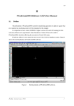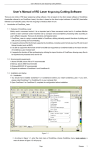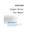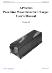
1
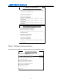
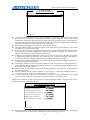
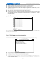
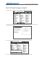
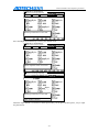
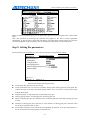
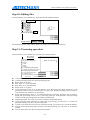
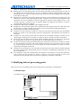
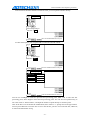
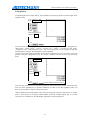
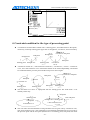
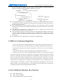
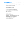
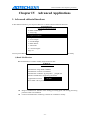
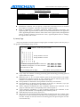
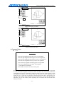
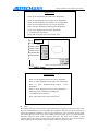
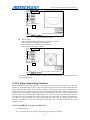
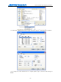
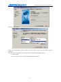
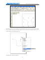
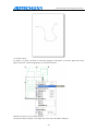
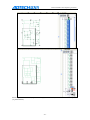
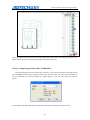
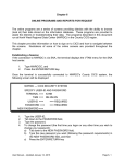
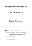
AD T- TV 55 00 DJ
User Manual for Three-axis Dispens
er Control System
Adtech (Shenzhen) Technology Co., Ltd.
Add: 5th floor,27-29th Bulding, Tianxia IC Industrial Park, Yiyuan Road, Nanshan
District, Shenzhen City, China
TEL: +86-755-2609 9116
P.C:518052
FAX: +86-755-2672 2718
email:[email protected] www.machine-controller.com
ADT-TV5500DJ 3-axis Dispensing Controller
Copyright Notice
The property rights of all the parts of the manual belong to Adtech (Shenzhen) CNC
Technology Co., Ltd. (Adtech for short), and any form of imitation, copying,
transcription or translation by any company or individual without the permission is
prohibited. This manual does not include any form of assurance, standpoint expression,
or other intimations. Adtech and the stuffs have no responsibility for any direct or indirect
disclosure of the information, benefit loss or business termination of this manual of the
quoted product information. In addition, the product and the information mentioned in
this manual are for reference only, and the content is subjected to change without notice.
ALL RIGHTS RESERVED!
Adtech (Shenzhen) Technology Co., Ltd
1
ADT-TV5500DJ 3-axis Dispensing Controller
Version Upgrading Instruction
Procedures
Version Number
Modification Date
Instruction
XT20090302
5.00
2009/9/08
The Fifth Version
Remarks: the meanings of the three numbers in the version number are as follows:
Bank Main Version Number/ Bank Secondary Version Number/ Reservation
Remark:
1、 This manual has been strictly carried out carefully and check the
collation by Adtech (Shenzhen) Technology Co., Ltd , but we can not guarantee
that this manual has no errors and frequent.
2 、 Adtech (Shenzhen) Technology Co., Ltd is committed to continuous
improvement of product functions, improve service quality, therefore,
reserves the handbook described in any of the products and software programs,
as well as the content of this manual to change without prior notice.
2
Content
Chapter I
System Overview........................................................................................................ - 4 Hardware Features...................................................................................................................... - 4 Software Features ....................................................................................................................... - 5 Fittings List ................................................................................................................................ - 5 Structural Dimensions ................................................................................................................ - 6 Keyboard layout ......................................................................................................................... - 8 Chapter II
Operating Instructions .............................................................................................. - 10 Step 1: Entering into the main interface ................................................................................... - 10 Step 2: Updating the programs ................................................................................................. - 10 Step 3: Viewing software version ............................................................................................. - 14 Step 4: Connecting and testing hardware ................................................................................. - 14 Step 5: Setting manufacturer parameters.................................................................................. - 16 Step 6: Setting system parameters ............................................................................................ - 18 Step 7: Setting processing parameters ...................................................................................... - 20 Step 8: Choosing/Creating processing file ............................................................................... - 21 Step 9: Setting file parameters.................................................................................................. - 23 Step 10: Editing files ................................................................................................................ - 24 Step 11: Processing operation................................................................................................... - 24 Chapter III
Details of File Edition .............................................................................................. - 25 1. File editorial interface........................................................................................................... - 25 2. Selecting instruction type of processing............................................................................... - 25 3. Modifying data of processing point...................................................................................... - 26 1) Manual input ................................................................................................................ - 26 2) Regulation .................................................................................................................... - 28 4. Constraint condition for the type of processing point .......................................................... - 29 5. Skills for Continuous Regulation ......................................................................................... - 30 6. List of Editorial Interface Key Function............................................................................... - 30 Chapter IV
Advanced Applications............................................................................................. - 32 1. Advanced editorial functions............................................................................................ - 32 1) Batch Modification....................................................................................................... - 32 2) Array Copy................................................................................................................... - 33 3) Figure Translation ........................................................................................................ - 34 4) Figure Zoom................................................................................................................. - 34 5) Z-axis Depth................................................................................................................. - 34 6) Needle Height .............................................................................................................. - 34 7) Batch Delete ................................................................................................................. - 34 8) Auto Fillet .................................................................................................................... - 34 9) Common Figure ........................................................................................................... - 35 2. PLT Figure Importing Function............................................................................................ - 37 1) Use CorelDRAW 12 to generate PLT files................................................................... - 37 2) Use AutoCAD2004 to generate PLT files .................................................................... - 39 3) Ways of Changing Sequence of PLT File Track with CorelDRAW12 ......................... - 42 4) Ways of Importing dxf files with CorelDRAW12........................................................ - 46 2. G Code Importing Function.................................................................................................. - 47 -
ADT-TV5500DJ 3-axis Dispensing Controller
Chapter I System Overview
TV5500DJ 3-axis dispensing controlling system (TV5500DJ for short) is a separate, 3-dimension, and
high precision motion control system consisting of TV5500 handheld box and ADT-8848 Offline
Motion Control Card, which are connected in the way of serial communicating. TV5500 performs the
operation of human-machine interface, and ADT-8848 performs the motion control and IO interface
operations. This system supports 3 motion axes and 8 dispensing output controls, providing users with
abundant instruction set, which includes motion instructions such as straight line, circular arc, single
point, and oval. In addition, instructions like port output, standby input, delay pause, selecting glue
gun, and motor reset are provided, as well as many other advanced editorial functions, including batch
modification, array copy, figure translation, figure zoom, auto fillet, and common figure library.
Except inputting coordinates manually and in regulation way, the system also supports importing PC
figures. PC figures can be converted to PLT file or G-code files, which will be further converted to
processing files of dispensing machine by controller for processing. Each processing file can save 100
thousand processing points. ADT-8848 has a 16M memory, while TV5500 has 128M. This system
also supports U disk reading and writing functions, which allow user to read and write the processing
files on U disk.
Hardware Features
z
z
z
z
z
z
z
z
z
z
z
z
z
z
Motor axis No.: 3 axes (XYZ)
Pulse frequency: 2MHz; if the pulse of motor per turn is 25600, the maximum speed can then
reach 5000 turn/min
Numbers of IO interface: 13-line special inputs (XYZ origin, positive & negative limit, start-up,
stop, reset and pause key), 22-line general input, 16-line special output (8 glue gun switch
controls; 8 glue gun switching controls, can be used as general output when glue gun is not used),
and 2-line general output;
IO input type: OC Isolation input
IO output type: NPN open collector 5-24VDC, rated current 0.5A; Maximum current of single
path can reach 1A.
Screen pixel of handheld box: 320 X 240, full color
Key No. of handheld box: 36
USB Function: Handheld box can be used as USB master and slave equipment; offline card can
be used as USB slave.
Memory space: 128M handheld box, 16M offline card; a processing file can occupy a space of as
large as 3M (100 thousand processing points)
Operating voltage: 24V DC
Operating temperature: 45°C
Storage temperature: -40°C —55°C
Operating humidity: 40%—80%
Storage humidity: 0%—95%
-4-
ADT-TV5500DJ 3-axis Dispensing Controller
Software Features
z
Support the line interpolation, and arc interpolation and elliptical arc interpolation of any two
axes in the 3-axis space.
z
Speed look-ahead algorithm is adopted to smooth the turning speed automatically.
z
PC picture import is supported. PLT files and G code files can be imported.
z
Feature the delay opening glue-gun and advance closing glue-gun for track, resolving the glue
piling at the starting point and the end-point.
z
Contain abundant motion instructions and auxiliary instruction sets.
z
With user-friendly file instruction and edition functions, offering many advanced editorial
functions such as batch modification, array copy, picture translation, picture zoom, and auto fillet;
common figure library is provided for users for their convenient use.
z
Graphical display function enables to show the shape of graphics in the processing files clearly.
z
Processing track is shown in real time dynamically.
z
Convenient and swift help system is provided. Help files can be shown by pressing Shift+F1 in
any interface.
z
Cycle processing, single processing, auto processing, and single step processing are supported.
Fittings List
Fitting Name
Model
Qty.
Profile
Handheld box
TV5500
1
Human machine interface
Offline card
ADT-8848
1
Motion and IO control
Data transmission
line
L01-202D9GG1
1
Used for the communication
between handheld box and
offline card
-5-
Appearance
ADT-TV5500DJ 3-axis Dispensing Controller
Structural Dimensions
Front view
Side view
ADT-8848
Structural
Dimensions Chart
Side view
-6-
ADT-TV5500DJ 3-axis Dispensing Controller
Rear view
Side view
Front view
TV5500 Structural
Dimensions Chart
Bottom view
-7-
ADT-TV5500DJ 3-axis Dispensing Controller
Keyboard layout
Needle
height
Regulation
Speed
Insert
Delete
Positioning
OK
Cancel
Keyboard Layout
Name
Icon
Functions
Function key
Perform a special function in an interface
Shift key
Used with other keys to perform different
functions, such as Shift+F1 to use help files
Editing key
Used to edit the parameters of processing point
in file edition
Needle height: Needle height of final point and
single point
Regulation: Programming XYZ coordinates
Insert: Insert a point ahead of the current point
Delete: Delete the current point
Positioning: Swiftly position the motor to the
coordinates of current point
-8-
ADT-TV5500DJ 3-axis Dispensing Controller
Used to choose the data need to be edited in the
editorial state
Direction key
: Up and Down key
: Left and Right key
Number key
Used to enter numbers or letters, select menu, or
used with Shift key to perform a special
function
OK/Cancel
Confirm or cancel the current operation
Manual key
: X-axis motor to move leftwards
or rightwards
: Y-axis motor to move forwards
or backwards
: Z-axis motor to move upwards
or downwards
: Not in use
: Switch the motor speed manually
-9-
ADT-TV5500DJ 3-axis Dispensing Controller
Chapter II Operating Instructions
Step 1: Entering into the main interface
When the machine is connected to the power supply and powered on, it enters the main interface as
below:
1.
Processing parameter settings
2.
Select/Create a new processing file
3.
File parameter settings
4.
File edition
5.
Processing
Press Shift +F1 to
view help files in
any interface
~
Processing file:\PRG\DRAWIN 2.DJJ
Step 2: Updating the programs
Program updating includes the updating of ADT-8848 and TV5500. ADT-8848 programs should be
updated prior to those of TV5500.
z There are two ways of updating ADT-8848 programs:
1) Updated via PC (The first time of updating must use this method.)
Connect the D-shape USB interface of ADT-8848 to the USB port of PC, and connect the second
serial Series2 of ADT-8848 with the PC serial; then, select “All programs ÆAccessories
ÆCommunicationsÆHyper Terminal” in Start menu of Windows:
Create a ne
w
- 10 -
ADT-TV5500DJ 3-axis Dispensing Controller
connection
Select the serial
Set the serial attribute following the picture below
Select the new Hyper Terminal window, and then re-electrify the controller. Press “ESC” key on
the PC keyboard within 1 second while re-starting, and enter the password to go to the BIOS
- 11 -
ADT-TV5500DJ 3-axis Dispensing Controller
interface:
- 12 -
ADT-TV5500DJ 3-axis Dispensing Controller
Follow the prompt to select “C.U Disk Function”Æ“1.U Disk Connection”. At this point, the
ADT-8848 is used as U disk connecting the PC. You can copy the client programs of ADT-8848
(File name: adtrom.bin) to “\ADT\” catalog of the controller via PC, and restart the controller.
Press “ESC” key within 1 second while restarting, input password to enter into BIOS interface,
and then follow the prompts to choose “B. BIOS Settings”Æ“2.Updating the programs” to finish.
Restart the controller to finish the program update.
z
z
2) Updated via TV5500 (Used when ADT-8848 has installed version 1.11 or higher master
program)
Connect the USB interface of ADT-8848 to the USB port of PC. The ADT-8848 will be used
as a U disk connecting the PC. You can copy the client programs of ADT-8848 (File name:
adtrom.bin) to “\ADT\” catalog of the controller via PC (or via the file management function
of handheld box), and then use TV5500 to enter manufacturer parameter settings interface to
select “Updating ADT-8848 Programs”. Then, restart the controller to finish the program
update.
There are two ways of updating TV5500 programs:
1) Updated via U disk
Insert the U disk contained with TV5500 client programs into the flat USB interface of TV5500;
then, enter the main interface of controller and press Shift+2 to go to file management interface.
You can then copy the TV5500 client programs (File name: adtrom.bin) in portable drive to
“\ADT\” catalog of the local disk, and restart the controller. Press “Cancel” key for 1~2 seconds
within 1 second while restarting, and input password to enter BIOS interface, then use the
Up/Down key to select “B. BIOS Settings”Æ “2. Updating the programs” to finish. Restart the
controller to finish the program update.
2) Updated via PC
Connect the D-shape USB interface of TV5500 to the USB port of PC, and restart the controller.
Then, press “Cancel” key for 1~2 seconds within 1 second while restarting, and input password
to enter BIOS interface, then use the Up/Down key to select “C. U Disk Function”Æ “1.
Communication connecting” to complete; in this way, TV5500 is worked as a U disk. You can
copy the TV5500 client programs (adtrom.bin) to “\ADT\” catalog of the controller via PC.
Restart the controller. Press “Cancel” key for 1~2 seconds within 1 second while restarting, and
input password to enter BIOS interface, then use the Up/Down key to select “B. BIOS
Settings”Æ “2. Updating the programs” to finish. After that, restart the controller to finish the
program update.
Preparing of start-up picture and the background picture of main interface
You can draw a 320*240 black & white picture using the self-contained “Graph” program of the
Windows. The start-up picture is named as “logo.bmp”, and the background picture of main
interface is named as “back.bmp”, both of which are saved in “\ADT\” catalog of TV5500.
- 13 -
ADT-TV5500DJ 3-axis Dispensing Controller
Step 3: Viewing software version
In main interface, press Shift+F2 to view the software version:
Version info
TV5500 main program version:
TV5500 communication program version:
Generation date of TV5500 program: 6/7/2009
Generation time of TV5500 program: 17:32:35
Terminal main program Version: 1.10
Terminal motion library version: 1.10
Terminal communication program version: 1.10
Generation date of terminal communication program:
Generation time of terminal program: 15/7/2009
Generation time of terminal program: 15:21:21
Edited by:TangGongyi
Step 4: Connecting and testing hardware
In main interface, press Shift+5 to enter the interface of hardware testing:
Input status: (Black background means “Open”)
Output control: (Black background means “Open”)
Coding feedback:
DI is input signal, and DO is output signal. Please follow the wiring diagram below to test whether the
positive inversion of motor is normal, and whether the input signal and output signal are one-to-one
corresponding.
- 14 -
ADT-TV5500DJ 3-axis Dispensing Controller
Z origin
X positive limit
X-axis driv
Y origin
VCCA is the common end of X & Y-axis co-anode
connection
VCCA is the common end of Z & U-axis co-anode
connection
X origin
External DC 24V
Common end
X negative limit
Y-axis drive
Y positive limit
Y negative limit
Z positive limit
Z negative limit
Z-axis drive
Start
Stop
External DC 24V
Reset
Glue gun switch 1
Pause
Glue gun switch 2
Glue gun switch 3
Glue gun switch 4
Glue gun switch 5
Client
Glue gun switch 7
GE
Glue gun switch 8
Switching gun 1
Switching gun 2
Switching gun 3
Switching gun 4
Item No.
Switching gun 5
Switching gun 6
Switching gun 7
Switching gun 8
Page
Version
ADTECH (SHENZHEN) CNC TECHNOLOGY CO., LTD.
Item name
Name of
figure Wiring diagram of ADT-8848
Drawn by Tang Gongyi Date
Glue gun switch 6
- 15 -
ADT-TV5500DJ 3-axis Dispensing Controller
Step 5: Setting manufacturer parameters
In main interface, press Shift+0 to enter the interface of manufacturer parameters setting:
Manufacturer Parameter Settings
0. Password for manufacturer parameter settings
1. X-axis motor characteristic settings:
2. Y-axis motor characteristic settings:
3. Z-axis motor characteristic settings:
4. Track split precision (mm):
5. Turning moderating ratio:
6. ADT-8848 program update:
Page 1 of 1
You can press Shift key and corresponding number key to select swiftly the parameters needs to be
edited.
z
z
z
z
z
Password for manufacturer parameter settings: This password is required when entering into the
manufacturer parameter settings interface. You can enter the interface directly if it is empty.
Motor characteristic settings: Including some parameters related to motor hardware
Track split precision: The controller splits all the pictures into tiny segments of equal length. The
track split precision is the length of a tiny segment. Too small the value may bring over large
amount of controller operations, influencing the motion effect. It is recommended to set the value
to be larger than the moving distance of 1/50 circle of motor turning.
Turning moderating ratio: The larger the value is, the less velocity decrement of the same turning
will be.
ADT-8848 program update: It is used for updating ADT-8848 client programs.
Select motor characteristic settings, and press OK key to enter:
X-axis Motor Characteristic Settings:
Pulse per turning (Pulse)
Pulse Equivalent (mm/Pulse):
Setup Wizard of Pulse Equivalent:
Reset Mode:
Reset Direction: Left
Effective Level of Origin Switch: Low level
Effective Level of Limit Switch: Low level
Effective Stroke (mm):
Maximum Speed (mm/s):
Page 1 of 1
z
z
z
z
z
Pulse per Turning: It is the pulse numbers required per each motor turning.
Pulse Equivalent: It refers to the moving distance of a pulse corresponding to motor.
Setup Wizard of Pulse Equivalent: Select two points on the platform, and calculate the pulse
equivalent according to the measured distance of these two points.
Reset Mode: There are two modes, to-and-fro reset, and circle reset. To-and-fro reset is usually
used in lead screw and belt driving mode; circle reset is used in rotary and cam driving mode.
Reset Direction: Before setting this parameter, please make sure whether the motor moving
direction while in regulating is corresponding to that of the motor manual button on the handheld
box.
- 16 -
ADT-TV5500DJ 3-axis Dispensing Controller
z
z
z
z
Effective Level of Origin Switch: You can check the effective level of origin in hardware testing.
When the motor is not in origin position, if the corresponding origin input signal is low level, the
effective level of origin will be the high level; otherwise, it will be the low level.
Effective Level of Limit Switch: You can check the effective level of limit in hardware testing.
When the motor is not in limit position, if the corresponding limit input signal is low level, the
effective level of limit will be the high level; otherwise, it will be the low level. The modified
parameter goes into effect only after the restart of the controller.
Effective Stroke: This parameter will affect the range of picture display when programming, and
the reachable area of motor movement. If you cannot ensure the effective stroke of motor in
advance, you can enter the file editorial interface to control the motor motion manually, and view
the coordinates to confirm the effective stroke of motor.
Maximum Speed: The maximum speed of stepping motor is usually 15 turning/s; and the servo
motor is 50 turning/s. The actual value should be determined by the test.
Setup Wizard of Pulse Equivalent:
Setup Wizard of X-axis Pulse Equivalent:
This wizard regulates the two points on the platform, and
calculates the pulse equivalent automatically according to the
measured distance of these two points (Appointed axis).
Step 1: Move the motor to the first point and mark it, then
press right direction key to go to the next step.
X-axis speed: 01000 pulse /s
Y-axis speed: 01000 pulse /s
Z-axis speed: 01000 pulse /s
Speed key + X left: X Deceleration Speed key+ X right: X
Acceleration
Speed key + Y back: Y Deceleration Speed key+ Y front: Y
Acceleration
Speed key + Z down: Z Deceleration Speed key+ Z up: Z
Acceleration
Setup Wizard of X-axis Pulse Equivalent:
Step 2: Move the motor to the second point and mark this
position, and then press the right direction key to go to the
next step. Press left direction key to return to the previous
step.
X-axis speed: 01000 pulse /s
Y-axis speed: 01000 pulse /s
Z-axis speed: 01000 pulse /s
Speed key + X left: X Deceleration Speed key+ X right: X
Acceleration
Speed key + Y back: Y Deceleration Speed key+ Y front: Y
Acceleration
Speed key + Z down: Z Deceleration Speed key+ Z up: Z
Acceleration
- 17 -
ADT-TV5500DJ 3-axis Dispensing Controller
Setup Wizard of X-axis Pulse Equivalent:
Step 3: Measure the distance between the first point and the
second point. Press right direction key for next step and left
direction key for the previous step.
X-axis speed: 01000 pulse /s
Y-axis speed: 01000 pulse /s
Z-axis speed: 01000 pulse /s
Speed key + X left: X Deceleration Speed key+ X right:
X Acceleration
Speed key + Y back: Y Deceleration Speed key+ Y front:
Y Acceleration
Speed key + Z down: Z Deceleration Speed key+ Z up: Z
Acceleration
Setup Wizard of X-axis Pulse Equivalent:
Step 4: Input the measured distance
Press OK to confirm, or Cancel to exit.
Please input the distance between the first point and the
second point (mm):
Input method: Numeral Input
X-axis speed: 01000 pulse /s
Y-axis speed: 01000 pulse /s
Z-axis speed: 01000 pulse /s
Speed key + X left: X Deceleration
Speed key+ X right:
X Acceleration
Step 6: Setting system parameters
In main interface, press Shift+1 to enter the interface of system parameters setting:
System Parameter Settings:
User password management:
X-axis motor parameter management:
Y-axis motor parameter management:
Z-axis motor parameter management:
Glue gun offset settings:
Conversion proportion of PLT files:
Settings of PLT gun pen relation:
Settings of G-code knife pen relation:
File number corresponding
Testing switch: Close
Page 1 of 1
- 18 -
ADT-TV5500DJ 3-axis Dispensing Controller
System Parameter Settings:
Reset test before running: No
Time interval of auto reset once electrified (s):
Page 2 of 2
z
z
z
z
z
z
z
z
z
z
User Password Management: You can set the administrative password, and Grade 1/2/3 password,
the priority level of which is descending accordingly. System parameter settings and the file
management require the administrative password; processing parameter settings require Grade-1
password; file parameter settings, file edition, and PLT file conversion require Grade-2 password;
and the processing file selection requires Grade-3 password.
Motor Parameter Settings: Set parameters related to motor speed.
Glue Gun Offset Settings: The relative position of the eight glue-guns has offsetting. You can use
this function to set the position offset.
PLT conversion proportion: Because the coordinate unit of PLT file is different from that of the
processing file, you need to multiply the conversion proportion to adjust it. The actual value is
related to the settings of software generating PLT files.
Settings of corresponding relationship of PLT gun pen: Pen of each color in PLT file corresponds
to a pen number. There are eight glue guns, glue gun 1 to 8, in the processing files. This function
is used to set the corresponding relationship of pen number and glue gun number.
Settings of corresponding relationship of G-code knife pen: Set the corresponding relationship of
G-code knife number and glue gun.
File number matching: There are 100 file numbers in total, each of which is corresponding to a
processing file. When using expanded display panel, you can select the corresponding processing
file by selecting the file number.
Debug switch: In general processing, please set this parameter to off; otherwise, it will influence
the processing effect.
Reset test before running: If this parameter is set to be "Yes", it will check whether the motor is
reset before running. It will reset automatically if it is not reset.
Time interval of auto reset once electrified: The controller is reset automatically after a while
once electrified. Auto reset is not performed if this parameter is of negative value.
Select motor parameter settings in the interface of system parameter settings, and press OK to enter
the interface of motor parameter settings:
X-axis Motor Parameter Settings
0.Starting Speed (mm/s):
1.Manual low speed (mm/s)
2.Manual high speed (mm/s)
3.Acceleration time of Travel (s):
4.Low speed reset (mm/s):
5.High speed reset (mm/s):
6.Acceleration time of reset (s):
Page 1 of 1
z
Starting Speed: Generally, the starting speed of stepping motor should not exceed 3 turnings per
second, and in case of servomotor, it should not exceed 5 turnings per second.
- 19 -
ADT-TV5500DJ 3-axis Dispensing Controller
z
z
z
z
z
z
Manual low speed: Used to locate the position accurately in manual regulation
Manual high speed: Used to locate the position swiftly in manual regulation
Acceleration time of Travel: It is the time required by changing from starting speed to travel
speed. The smaller the value is, and the faster of speed change will be. If it is set to be 0, it means
the uniform velocity.
Low speed reset: Used to locate the position accurately when resetting
High speed reset: Used to locate the position swiftly when resetting
Acceleration time of reset: It is the time required by changing from low speed reset to high speed
reset. The smaller the value is, and the faster of speed change will be. If it is set to be 0, it means
the uniform velocity.
Select glue-gun offset settings in the interface of system parameter settings, press OK to enter
glue-gun offset settings interface:
Regulate the Reference Point of Glue Gun
Regulate the reference point of glue gun
Offset settings of glue gun 1
Offset settings of glue gun 2
Offset settings of glue gun 3
Offset settings of glue gun 4
Offset settings of glue gun 5
Offset settings of glue gun 6
Offset settings of glue gun 7
Offset settings of glue gun 8
Page 1 of 1
Set the reference point of glue gun using the glue gun 1, and then adjust the offset of other glue guns
according to this reference point.
Step 7: Setting processing parameters
In main interface, press number key (1) to enter the interface of processing parameters setting:
Processing Parameter Settings
Travel speed of XY-axis (mm/s):
Fall speed of Z-axis (mm/s):
Lifting speed of Z-axis (mm/s):
Acceleration time of Z-axis lifting (s):
z
z
z
z
Page 1 of 1
Travel speed of XY-axis: Speed of XY swift location
Fall speed of Z-axis: Speed of Z-axis swift location downwards
Lifting speed of Z-axis: Speed of Z-axis swift location upwards
Acceleration time of Z-axis lifting: It is the time required by changing from starting speed to fast
location speed. The smaller the value is, and the faster of speed change will be. If it is set to be 0,
it means the uniform velocity.
- 20 -
ADT-TV5500DJ 3-axis Dispensing Controller
Step 8: Choosing/Creating processing file
In main interface, press number key (2) to enter the processing file selection interface:
Select Processing File[DJJ]
Copy (1) Paste (2) Delete (3)
New (4)
Preview(5)
Current catalog:
Bytes
Bytes
Bytes
Bytes
Up (-)
Previous
Next
Use Up/Down/Left/Right key to select your desired file, press OK to select, and press number key (5)
to preview the selected file:
Processing File Preview
X Left: View port is moved leftwards
X Right: View port is moved rightwards
Y Front: View port is moved forwards
Y Back: View port is moved backwards
Z Up: Figure zooms out
Z Down: Figure zooms in
Speed: Resume default size
In the interface of selecting processing file, press number key (4) to create a new file:
Select Processing File[DJJ]
Copy (1) Paste (2) Delete (3)
New (4)
Preview (5)
Current catalog:
Bytes
Bytes
Bytes
Please input the name of new file:
Input method: Chinese
You can press Shift key to change the input method to enter Chinese in Pinyin mode:
- 21 -
ADT-TV5500DJ 3-axis Dispensing Controller
Select Processing File[DJJ]
Copy (1) Paste (2)
Delete (3)
New (4)
Preview (5)
Current catalog:
Bytes
Bytes
Bytes
Please input the name of new file:
Press Left/Right and number key to select your desired word:
Select Processing File[DJJ]
Copy (1) Paste (2)
Delete (3)
New (4)
Preview (5)
Current catalog:
Bytes
Bytes
Bytes
Please input the name of new file:
Select Processing File[DJJ]
Copy (1) Paste (2)
Delete (3)
New (4)
Preview (5)
Current catalog:
Bytes
Bytes
Bytes
Please input the name of new file:
Input method: Chinese
When the input method is in Chinese or letter input mode, you can press decimal point (.) key to input
the punctuation:
- 22 -
ADT-TV5500DJ 3-axis Dispensing Controller
Select Processing File[DJJ]
Copy (1) Paste (2) Delete (3)
New (4)
Preview (5)
Current catalog:
Bytes
Bytes
Bytes
When you have finished the input, you can press OK to generate a processing file with a “.DJJ” suffix
name.
Note: The operation of processing file selection only applies to the files in remote equipment
(ADT-8848). To process files in local disk (TV5500) or removable disk (U disk), please copy the files
to remote equipment using file manager (can be called by pressing Shift+2 in main interface).
Step 9: Setting file parameters
In main interface, press number key (3) to enter the interface of file parameter setting:
File Parameter Settings
Track speed (mm/s):
Trackaccelerationtime(s):
Dispensingdelay (s):
Closinggluegundelay (s):
Delay ofopeningglue gun(s):
Distanceofclosingglueguninadvance(mm):
Filenumber matching..
Page 1 of 1
z
z
z
z
z
z
z
Each file has independent file parameters.
Track speed: The speed of track processing
Track acceleration time: It is the time needed to change from starting speed to track speed. The
smaller the value is, the faster the speed change will be. If it is set to be 0, it is processed evenly
with the track speed.
Dispensing delay: A responding time of opening the glue gun
Closing glue gun delay: A responding time of closing glue gun
Delay of opening glue gun: It is the delay time of opening glue gun when delay opening glue gun
is used.
Distance of closing glue gun in advance: It is the distance of closing glue gun in advance when
the advance closing function is used.
File number matching: View and set the corresponding file number of the file. This function is
for the convenience of choosing files in numerical way.
- 23 -
ADT-TV5500DJ 3-axis Dispensing Controller
Step 10: Editing files
In main interface, press number key (4) to enter the file editorial interface:
Type: Starting point
Speed
Delay dispensing: No
Point number:
For detailed functions of file edition, please see Chapter III “Details of File Edition”.
Step 11: Processing operation
In main interface, press number key (5) to enter processing interface:
Processing
Current status: Stop
Current processing point:
0. Reset
1. Start
2. Stop
3. Pause
4. Cycleprocessing: Cycleprocessing
5. Single step processing: Auto
6. Dispensing enable: Enable
7. Cycle processing time:
8. Current cycle:
9. Total of current processing:
Error status:
z
z
z
z
z
z
z
z
z
z
z
z
z
Shift +Z: Preview
Error point number:
Current status: the current operating status
Current processing point: the current processing point
Reset: Press "0" to reset
Start: Press "1" to start operation.
Stop: Press "2" to stop operation
Pause: Press "3" to pause
Cycle processing: Press "4" to switch between cycle processing and single processing. Cycle
processing means to process following the set cycle time. Single processing means to process
once after the start, without cycle processing.
Single step processing: Press "5" to switch between auto processing and single step processing.
Single step processing means to run a processing point per each operation. Auto processing
means to run the processing points in sequence automatically.
Dispensing enable: You can press "6" key to enable or disable dispensing.
Cycle processing times: Show the set cycle times of processing; you can press "7" to enter user
parameter setting to set the cycle processing times.
Current cycle: Show the cycle times of current processing; you can press "8" to clear the number.
Total of current processing: Show the total of current processing; you can press "9" to clear the
number.
You can press Shift +Z to preview the processing files.
- 24 -
ADT-TV5500DJ 3-axis Dispensing Controller
Chapter III Details of File Edition
1. File editorial interface
Parameter info of
加工点参数信息
processing
point
Type
Figure and track
图形、轨迹显示区
display
area
End-point
Speed
Needle
height
Close dispensing in
advance: (No)
Real
time
实时坐标显示区
coordinate
Point
number of
加工点点号
processing
point
Info
area
信息提示区
Point
number
Files are modified and not saved yet!
当前点号
Current
point
总点数
Total
point
2. Selecting instruction type of processing
In file editorial interface, use Up/Down key to move the cursor to “Type” column, and press OK, an
interface for selecting type of processing point appears:
Select the type of processing
z
z
z
z
z
z
Motor reset
Port output
Standby input
Delay pause
Select glue gun
Glue gun control Starting point
End-point
Straight line
Single point
Travel
Clockwisecirculararc
Anti-clockwisearc
Circular arc
Circle
Circulararcend-point
Clockwise oval
Anti-clockwiseoval
Oval
end-point
Motor reset: Specifying one or some motors to reset; the appointed motor go on performing the
next instruction after the reset
Port output: Specifying some port outputs to switch on or off signal, and keep performing the
next instruction after the set delay time
Standby input: Wait for some input ports to open/close to perform the next action; a standby
delay time can be set
Delay pause: Keep on performing the next step after the set delay time; if the delay time is 0, the
program is paused until Start or Pause key is pressed again.
Select glue gun: Select the operating glue gun. It is default to be the first one.
Glue gun control: It is capable of controlling a glue gun to open and close independently. This
instruction is usually used in figure importing function. Generally, “Starting point” and “End
- 25 -
ADT-TV5500DJ 3-axis Dispensing Controller
z
z
z
z
z
z
z
z
z
z
z
point” or “Single point” instructions are used to control the open/close of glue gun.
Starting point: It is the starting point of track. When processing, insert the glue gun at Z-axis of
the starting point and open the gun. You can set whether to delay opening the glue gun at the
starting point. If so, it does not open the glue gun when moved to the starting point, but opening
it after the set delay time.
End-point: It is the end-point of track. When processing, close the glue gun at the end-point, and
make Z-axis return to the needle height position. A figure can have several starting points and
end-points. You can set whether to close the glue gun in advance at the endpoint. If so, it will
close the glue gun in advance at the set distance before the endpoint. This function is used to
avoid the piling glue at the endpoint.
Straight line: Run to this coordinate at the straight-line mode.
Single point: Locate the XY quickly first, and then insert the glue gun at Z-axis. After that, open
the glue gun for a while, and then close it; then, Z-axis returns to the needle height position.
Travel: XYZ is located to this point quickly.
Clockwise & Anti-clockwise circular arc: The previous point and next point must be bonded,
forming a circular arc by specifying circular arc starting point, semi-diameter, and circular arc
end-point.
Circular arc: The previous point and next point must be bonded, forming a circular arc by
specifying the starting point of circular arc, a point on the arc, and the circular arc end-point.
Circle: The previous point and next point must be bonded, forming a circular arc by specifying
the starting point of circular arc, a point on the arc, and the other point on circular arc.
Circular arc end-point: This point should follow the instruction of circular arc, clockwise circular
arc, anti-clockwise circular arc, and circle to bind with the previous two points to form a circular
arc. If the end-point of circular arc is the end-point of track, the end-point of circular arc can be
replaced by “End-point” instruction.
Clockwise & Anti-clockwise oval: The previous point and next point must be bonded, forming
an oval by specifying the starting point of oval, oval center, semi-diameter of long/short axis, and
the oval end-point.
Oval end-point: This point should follow the instruction of clockwise oval and anti-clockwise
oval to bind with the previous two points to form an oval. If the end-point of oval is the
end-point of track, the end-point of oval can be replaced by “End-point” instruction.
3. Modifying data of processing point
There are two ways of modifying data of processing point, manual input, and regulation.
1) Manual input
Use Up/Down key to move the cursor to the data column needs to be modified:
Type
Starting point
Speed
Close dispensing in
advance: (No)
Point
number
Files are modified and not saved yet!
- 26 -
ADT-TV5500DJ 3-axis Dispensing Controller
If the format of this data column is numerical value, you can input the number directly:
Type
Starting point
Speed
Close dispensing in
advance: (No)
Point
number
Files are modified and not saved yet!
If it has multi options, you can press OK to switch the selected content:
Type
Starting point
Speed
Close dispensing in
advance: Yes
Yes
Point
number
Files are modified and not saved yet!
Type: Select glue gun *
Glue gun 1 ON
Glue gun 2 Off
Glue gun 3 Off
Glue gun 4 Off
Glue gun 5 Off
Glue gun 6 Off
Glue gun 7 Off
Glue gun 8 Off
Point
number
Files are modified and not saved yet!
You can use Left/Right to select the previous/next processing point, Shift +Left to select the first
processing point, Shift +Right to select the last processing point. You can also use Up/Down key to
move the cursor to “Point number”, and input the number of point directly to select the point.
Note: If the file is not saved after the modification, there will be a “*” prompt next to the type column.
You can press Shift+F2 to save the file. To run or test the file, you have to save the file first; otherwise,
it will run the data before saving.
- 27 -
ADT-TV5500DJ 3-axis Dispensing Controller
2) Regulation
Except being able to be input directly, the coordinates of processing point can also be input in the
regulation way:
Type
Starting point
Speed
Close dispensing in
advance: (No)
Point
number
First, select the processing type. Only the coordinates of such types as “Origin”, “Straight line”,
“End point”, “Single point”, “Travel”, “Circular arc”, “Circle”, “Circular arc end point”,
“Clockwise oval”, “Anti-clockwise oval”, and “Oval end point” can be regulated. Only the
needle height of “Origin” and “End point” can be regulated.
Once the processing point is selected, use the motor manual key to move the motor to the aim
position, and press “Regulation” key, the current coordinate will be saved in the processing
point.
Type
Starting point
Speed
Close dispensing in
advance: (No)
Point
number
Files are modified and not saved yet!
Note: For the convenience of continuous regulation, the current point number will become the
next one when regulation key is pressed. Therefore, in order to view the regulation result, you
have to use Left key to return to the previous point.
When regulating the needle height, select the processing type (must be “End point” or “Single
point”), move Z-axis to the proper needle height, and press “Needle height” key to save the
current Z-axis coordinate in “Needle height” parameters of processing point.
- 28 -
ADT-TV5500DJ 3-axis Dispensing Controller
Type
End-point
Speed
Needle
heigh
Close dispensing in
advance: (No)
Point
number
Files are modified and not saved yet!
4. Constraint condition for the type of processing point
z A continuous track should be started with a “Starting point”, and ended with an “End point”,
which may contain processing point types such as straight line, circular arc, and oval midway.
Straight line
Straight line
End-point
Starting point Straight line
Circular arc end-point
End-point
Starting point
Circular arc
z “Clockwise circular arc”, “Anti-clockwise circular arc”, “Circular arc”, “Circle”、“Clockwise
oval”, and “Anti-clockwise oval” instructions should not be used independently, and should
be combined with the previous point and the next point to form a figure.
Circular arc end-point
End-point
Circle
End-point
Circle
Circular arc
Starting point
Starting point
End-point
Starting point
z The End Point of “Circle” is superposed with the starting point. The “End Point” is for
auxiliary effect only.
End-point
1 Starting point
3 End-point
Oval end-point
Straight line 1 Starting point
3 Anti-clockwise oval
2 Clockwise ova
z The oval center and semi-diameter of long and short axes are given out by “Clockwise oval”,
and “Anti-clockwise oval”. The coordinates of oval Starting and End Points are given out by
the previous point and the next point (Because the oval starting point, end-point, and center
- 29 -
ADT-TV5500DJ 3-axis Dispensing Controller
are not convenient to regulate, you can use the “Common figure” in advanced edition to
regulate a rectangle to help complete the regulation of an oval).
Straight line 8 End-point Circular arc end-point
1 Starting point
3 Anti-clockwise arc
3 Anti-clockwise arc
Circular arc end-point 5
z
z
z
z
z
Single point Single point
Single point
Single point
Straight line
“Anti-clockwise circular arc” and “Clockwise circular arc” instructions only specify the arc
semi-diameter, and the coordinates of arc starting point and end-point. They are given out by
the previous and next points.
The semi-diameter of the “Anti-clockwise circular arc” and “Clockwise circular arc” should
not be set to be less than half of distance between these two points; otherwise, it cannot form
a circular arc.
The regulation of “Single point” is much easier; however, “Single point” cannot be used
combining with circular arc or oval instruction.
“Travel” instruction means to locate the XYZ axes to the appointed coordinates swiftly at the
same time without opening or closing the glue gun. “Starting point” instruction is to locate
XY axes swiftly to the appointed position, and then locate the Z-axis, together with opening
the glue gun.
Only “End-point” and “Single point” can regulate the “Needle height”.
5. Skills for Continuous Regulation
To easy and convenient to finish the regulation of a figure, three switching shortcuts are set:
F1 key: Switch the type of current processing point to Origin, Straight line, and End-point.
F2 key: Switch the type of current processing point to Circular arc, Circle, and Circular arc
end-point.
F3 key: Switch the type of current processing point to Single point and Travel.
In addition, the software contains intelligent judgment function; it can generate the type of
next point according to the type of previous point. For example, if the previous point is “Starting
point”, the next point will be the “Straight line” automatically. If the previous point is “End
point”, the next point will be the “Starting point”; if the previous point is “Circular arc”, the next
point will be the “Circular arc end-point”; and if the previous point is “Single point”, the next
point will be the “Single point”. In addition, the set parameters, such as “Single point time”,
“Needle height”, and “Speed”, will be recorded automatically and applied to the next point.
When inserting a new processing point, it will generate the processing point of proper type
according to the types of processing point before and after.
6. List of Editorial Interface Key Function
z
z
z
Shift+ OK: Run/Pause
Shift+ Cancel: Stop/Reset
XYZ manual key: Move the motor manually
- 30 -
ADT-TV5500DJ 3-axis Dispensing Controller
z
z
z
z
z
z
z
z
z
z
z
z
z
z
z
z
z
z
z
z
z
z
z
Speed: Switch the high and low speed manually
Tech-in key: Save the current coordinate in the current point and jump to the next point
Needle height: Save the current Z-axis in the needle height parameters of the current point
Insert: Insert a point ahead of the current point
Delete: Delete the current point
Positioning key: Set the motor to the current point
Up/Down: Select data need to be modified
OK: Make the modification
Left/Right: View the previous/next point
F1: Type switching (Starting point/straight line/end point)
F2: Type switching (Circular arc/Circle/Circular arc end point)
F3: Type switching (Single point/Travel)
Shift+F1: Call the help files
Shift+F2: Save files
Shift+F3: Advanced editorial functions
Shift+ Delete: Delete all
Shift+ Left key: Jump to the first point
Shift+ Right key: Jump to the last point
Shift+ Positioning: Jump to the latest point from the current position
Shift+ decimal point (.): Move the picture horizontally
Shift+ Negative Sign (-): Adjust the depth of Z-axis uniformly
Shift+0: Browse the appointed processing point
Cancel key: Exit the editorial interface
- 31 -
ADT-TV5500DJ 3-axis Dispensing Controller
Chapter IV Advanced Applications
1. Advanced editorial functions
In file editorial interface, you can press Shift+F3 to call the advanced edition functions:
Advanced Editorial Function
0. Batch modification
1. Array copy
2. Figure Translation
3. Figure Zoom
4. Z-axis Depth
5. Needle Height
6. Batch Delete
7. Auto Fillet
8. Common Figure
Page 1/1
You can press Shift and corresponding number key to select your desired edition function swiftly.
1) Batch Modification
Batch modification is used to modify large amount of data.
Batch Modification
Modification range:00001Æ000021
Modification content: X coordinate
Modification condition: Type Equal to _straight line
Mode of modification: Appointing increment
Appointed increment:
-50.0000
Press Shift +OK to perform batch modification
z
z
Range of modification: Number of the starting processing point and closing processing
point that need to be modified
Content of modification: Following contents are available to modify:
- 32 -
ADT-TV5500DJ 3-axis Dispensing Controller
Select Modification Content
X coordinate
Y coordinate
Speed
Dispensing time
TypeCircular arc semi-diameter
z
z
Z coordinate
Needle height
Delay dispensing Close dispensing in advance
Modification condition: You can specify a certain data of the data need to be modified
to be equal to, not equal to, more than, or less than an appoint value.
Mode of modification: It includes Appointing Value, Appointing Increment, and
Appointing Rate. Appointed Value means to set the modified contents as the appointed
value. Appointing Increment means to add a value to the original value (if the appointed
value is a negative number, it decreases the value). Appointing Rate means to multiply
the original value with a value.
2) Array Copy
Array copy function is used to replicate a single figure to multiple copies in the array way, it
can generate a parallelogram array as well.
Copy range: 00001Æ00008 Reference point A:00001
Group numbers at X-axis
Group numbers at Y-axis
Coordinate of end-point B at X-axis direction
Coordinate of end-point C at Y-axis direction
Initial direction:AÆB
Way of changing line: S-shape
(Press Shift +OK to generate array)
z
z
z
z
z
z
z
z
Copy range: the numbers of starting processing point and closing processing point of
figure needs to be copied
Reference point A: It is a certain reference point on the figure needs to be copied.
Regulating the distance between X and Y direction needs to take this point as the
reference. It is default to select the first point of the figure.
Group numbers in X direction: Group numbers of the array in X direction
Group numbers in Y direction: Group numbers of the array in Y direction; if you just
copy once, set the group numbers in XY direction to one.
X-axis end-point (Coordinate B): This coordinate should be the coordinate of last
group in X direction that is corresponding to the reference point A.
Y-axis end-point (Coordinate C): This coordinate should be the coordinate of last
group in Y direction that is corresponding to the reference point A.
Initial direction: From A to B, or from A to C
Way of new line: It includes S-shape and Z-shape of changing new line. Z-shape: when
the process of a line is finished, it will return to the starting point to start processing the
next line. S-shape: It does not return to the starting point, but processing the next line
in a turn-back way.
- 33 -
ADT-TV5500DJ 3-axis Dispensing Controller
3) Figure Translation
This function is mainly used to adjust the XY coordinates of figure uniformly. First, confirm
the starting point of the figure, and then move XY-axis to XY coordinate that the starting point
needs to move. After having applied this function, the whole figure is moved horizontally to the
current position automatically. This function can be called by pressing Shift +decimal key in the
file editorial interface.
4) Figure Zoom
This function is used to zoom in and zoom out the value of XY coordinates. Indifferent
from the batch modification way, this function can zoom in and out the semi-diameter of the
circular arc and oval.
5) Z-axis Depth
This function is used to adjust the Z-axis coordinate and needle height uniformly. First,
confirm the starting point of the figure, and then move Z-axis to Z coordinate that the point needs
to adjust. After having applied this function, the Z-axis coordinates and the needle height of the
whole figure will be adjusted according to the value of Z-axis. This function can be called out by
pressing Shift +Negative (-) key in the file editorial interface.
6) Needle Height
This function changes the value of needle height in relation to Z-axis coordinate.
For example, the processing point type of a point is “Single point”, Z-axis coordinate is -70,
if you set the needle lifting height to be 30, the needle height of this point is then changed to
(-70+30) = -40。
7) Batch Delete
Select the range of processing points that need to be deleted, and press Shift +OK to delete.
To delete all, you can press Shift +Delete in the file editorial interface.
8) Auto Fillet
This function is used to change the break angle to circular arc. The arc length of circular arc
can be set. If the side length of these two break angles is not enough for changing to the set arc length,
the fillet arc length will be reduced automatically to fit for the side length of break angle.
Auto Fillet
Modification range:00001Æ000021
Length of fillet arc:
Press Shift +OK to finish auto fillet
Prompt: Please save or backup files before
performing auto fillet.
- 34 -
ADT-TV5500DJ 3-axis Dispensing Controller
Type
Starting point
Speed
Close dispensing in
advance: (No)
Files are modified and not saved yet!
Point
number
Before performing auto fillet
Type
Straight line
Speed
Point
number
Files are modified and not saved yet!
After performing auto fillet
9) Common Figure
z
Oval
Generate Oval
Shift +X left: Regulate/cancel left vertex: Not regulated
Shift +X right: Regulate/cancel right vertex: Not regulated
Shift +X back: Regulate/cancel bottom vertex: Not regulated
Shift +X front: Regulate/cancel up vertex: Not regulated
Shift +Z down: Regulate the starting point: Not regulated
Shift +Z up: Regulate the end-point: Not regulated
1. Oval direction: Clockwise
Shift +OK: Insert the oval to the current point
Press Shift+ XY key in the interface of oval to regulate all vertexes of the oval (To generate
an oval, you need to regulate at least one vertex at both X and Y directions). Press the
combination key once to regulate the coordinate, and press for the second time to cancel
the regulated coordinates. Once starting point and end point have been regulated, press
number key (1) to select the oval direction, and then press Shift +OK to generate the oval.
The data of all vertexes in this interface are saved at all times, even you exit the interface.
Therefore, you can exit midway while regulating the oval and the data will still be there
when you re-enter.
- 35 -
ADT-TV5500DJ 3-axis Dispensing Controller
Generate Oval
Shift +X left: Regulate/cancel left vertex: Regulated
Shift +X right: Regulate/cancel right vertex: Regulated
Shift +X back: Regulate/cancel bottom vertex: Regulated
Shift +X front: Regulate/cancel up vertex: Regulated
Shift +Z down: Regulate the starting point: Regulated
Shift +Z up: Regulate the end-point: Regulated
1. Oval direction: Clockwise
Shift +OK: Insert the oval to the current point
Type
Straight line
Oval plane:
Circular center X:
Circular center Y:
Circular center Z:
X semi-diameter:
Y semi-diameter
Point
number
Files are modified and not saved yet!
The final oval
Generate Track
Shift +X left: Regulate/cancel left vertex: Regulated
Shift +X right: Regulate/cancel right vertex: Regulated
Shift +Y back: Regulate/cancel bottom vertex:
Regulated
Shift +Y front: Regulate/cancel up vertex: Regulated
0. Starting point: Left/Bottom middle point
1. Track direction: Clockwise
Shift +OK: Insert track to the current point
z Track
Press Shift+ XY key in the interface of generated track to regulate all vertexes of the track.
Press the combination key once to regulate the coordinate, and press for the second time to
cancel the regulated coordinates. You can press number key (0) to select the starting point
(the starting point can only occur in the middle of the long side), press 1 to select the track
direction, and press Shift +OK to generate the track. The data of all vertexes in this
interface are saved at all times, even you exit the interface. Therefore, you can exit midway
while regulating the oval and the data will still be there when you re-enter.
- 36 -
ADT-TV5500DJ 3-axis Dispensing Controller
Type
Starting point
Speed
Close dispensing in
advance: (No)
Files are modified and not saved yet!
Point
number
The generated track figure
z
Testing figure
Step 1: Select the plane where the testing figure is located;
Step2: Input the side length of testing figure;
Step3: Regulate the coordinate of the third axis;
Step4: generate the figure as below:
Type
Starting point
Speed
Close dispensing in
advance: (No)
Point
number
Files are modified and not saved yet!
You can use the figure translation or batch modification function to move the figure to the
appropriate position.
2. PLT Figure Importing Function
Set the PLT file conversion proportion in system parameters, and then press Shift +6 in the main
interface to select PLT files to convert them into processing files of the same name ended with .DJJ
suffix. After that, press Shift +2 to call file manager to copy the processing files to ADT-8848 for
testing and processing. PLT format is a format of printing file containing XY coordinate, starting point,
end-point, and color of figure without info about Z-axis coordinate. Therefore, figure after conversion
does not have Z-axis coordinate and needle height value. You can use the batch modification function
to modify the Z-axis coordinate and needle height. There are many kinds of software generating PLT
files. Here, we just introduce the ways of generating PLT files using two kinds of widely used
software: CorelDRAW 12 and AutoCAD 2004. The interface may be a little bit different in case of
different version.
1) Use CorelDRAW 12 to generate PLT files
<1>. Draw the figure
<2>. Click menu “File” Æ “Export”, and a dialog box appears as follows:
- 37 -
ADT-TV5500DJ 3-axis Dispensing Controller
<3>. Select PLT-HPGL Plotter File in “Type”, and click “Export”, a dialog appears as follows:
<4>. In “Page” tab, select “Bottom left” in “Graphic plotter origin”, and leave other settings as
default.
- 38 -
ADT-TV5500DJ 3-axis Dispensing Controller
<5>. In “Advance” tab, tick off “No wide or speed order”, and leave others as default. Then,
press OK to generate PLT file.
2) Use AutoCAD2004 to generate PLT files
Please check whether there is a printer named “Universal SHPGL” in printer type. If no, follow the
following steps to install:
Click menu “File” Æ “Printer Manager”, and a picture as below appears
Double click the icon of “Add Printer Wizard”, and click “Next” to enter the following interface:
- 39 -
ADT-TV5500DJ 3-axis Dispensing Controller
Continue to click “Next”
Select “Universal SHPGL” printer of HP, and keep clicking “Next” until the finish of printer
installation.
After the finish of installation, you can then export the PLT file following the steps as:
<1>. Draw a figure
<2>. Click “File” Æ “Print”, and the following dialog box appears
- 40 -
ADT-TV5500DJ 3-axis Dispensing Controller
<3>. Select “Universal SHPGL.PC3” printer in “Printer device”, check the “Print to file” check
box, and set the path and name of the exported file
<4>. In “Print setup”, uncheck “Print style” and “Line width of printing object” in the printing
options. Pay attention to the selection of “Figure direction”. A wrong selection may lead to
wrong direction of the exported figure (Take letter “A” normal display as standards).
- 41 -
ADT-TV5500DJ 3-axis Dispensing Controller
<5>. Click “OK” to export PLT file
PLT file can be opened by text editor. The following is a sample of PLT file:
_.(;_.I81;;17:_.N;19:IN;SC;PU;IP;IW;VS20,1;VS20,2;VS20,3;VS20,4;VS20,5;VS20,6;VS20,7;
VS20,8;SP1;PU;PA0,0;SP1;LT;PA3985,3940;PD;PA5344,3940;PA5344,2497;PA3985,2497;PA3
985,3940;PU;PA0,0;SP;PG1;
3) Ways of Changing Sequence of PLT File Track with CorelDRAW12
<1>. The adjustment of point sequence inside the curve
As shown in picture above, we can see that one endpoint of the curve is big and the other
one is small. Big endpoint means the starting point, and the small endpoint means the end-point.
To change their sequence, use the method below:
- 42 -
ADT-TV5500DJ 3-axis Dispensing Controller
Left click on the icon on the second row of the left toolbar, select shape tool (as above picture), right
click an endpoint of the curve, and select “Reverse curve”; then, the point sequence within the curve
will be changed. (As the following picture)
The figure after reversing is as follows:
- 43 -
ADT-TV5500DJ 3-axis Dispensing Controller
<2>. Figure sorting
If a figure is a group, you need to cancel the grouping of the figure. To do this, right click on the
figure, and select “Cancel all grouping” (As the picture below):
Generate several curves (As picture below):
(To open the object manager on the right side, click “Tool”Æ“Object manager”)
- 44 -
ADT-TV5500DJ 3-axis Dispensing Controller
Select any one of the curves (As picture above), you can name it, and move it to the desired position
(as picture below):
- 45 -
ADT-TV5500DJ 3-axis Dispensing Controller
Export PLT file when the sequence is arranged. Remember the position of starting point, which is the
position when setting the starting point position during the processing.
4) Ways of Importing dxf files with CorelDRAW12
After generating dxf file with AutoCAD, you have to close AutoCAD before importing dxf file
into CorelDRAW; otherwise, the import will fail. Pay attention to the unit when using AutoCAD. If
you use millimeter, the zoom unit should use “Metric system”; if you use inch, select the “Imperial
system”.
You’d better put the imported figure on the bottom left corner of the page (as picture below)
- 46 -
ADT-TV5500DJ 3-axis Dispensing Controller
2. G Code Importing Function
In main interface, you can press Shift +7 to switch the G code files to processing files with a
suffix name of .DJJ.
The supported G codes nowadays include G00, G01, G02, G03, G17, G18, G19, G90, G91, G20, G21,
and too change instruction begun with T.
- 47 -