1
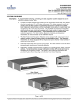
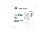
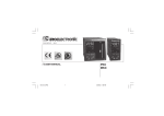
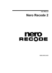
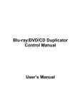
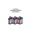
0831106
Rev.0
Calibration procedure
MKP
PKP
MKC
PKC
Calibration procedure for MKP - PKP
D
INSTRUMENT CALIBRATION
PROCEDURES
1 GENERAL GUIDELINES FOR CALIBRATION
C
For an accurate calibration it is necessary to proceed as follows:
a) - The instrument under calibration should be mounted in its case in
order to keep the internal temperature stable.
b) - The ambient temperature should be stable.
Avoid any drift due to air-conditioning or others.
c) - The relative humidity should not exceed 70%.
d) - The instrument must be in ON condition from 20 minutes at least.
e) - Operate, possibly, in an environment with no electromagnetic
disturbances.
f) - During calibration, connect to the instrument one input at a time.
g) - Before to execute each calibration, be sure that the specific
hardware setting has been made (see "Preliminary hardware
setting" paragraph).
D
Fig. 2
2.2 MAIN INPUT SELECTION
Set J103 (see fig. 3) according to the desired input type as shown in
the following table.
For this calibration procedure it is necessary to use calibrators with
the following accuracy and resolution:
J103
ACCURACY
1) For current input: + 0.025% output + 0.0025% range + 0.01 µA
2) For voltage input : + 0.005% output + 0.001% range + 5 µV
3) For TC input: + 0.005% output + 0.001% range + 5 µV
4) For RTD input: + 0.02 % + 0.0025 Ω/decade.
5) For cold junction compensation: better than 0.1 °C
1-2
3-4
5-6
7-8
5-7
6-8
RESOLUTION
1) For current input: 0.5 µA
2) For voltage input: 100 µV
3) For TC input: 1 µV
4) For RTD input: 10 mΩ
5) For cold junction compensation: better than 0.1 °C
INPUT TYPE
T/C, RTD,CJ
60 mV
5V
10 V
20 mA
open
open
open
open
close
close
open
open
open
open
close
close
close
close
open
open
open
open
open
close
open
open
close
open
open
open
close
close
open
open
1
3
5
7
J102
2
4
6
1
3
2
4
5
7
6
8
J103
8
CPU
card
2 PRELIMINARY HARDWARE SETTINGS
2.1 HOW TO REMOVE THE INSTRUMENT
FROM ITS CASE
1) Switch off the instrument.
2) Push gently the lock A on the right.
3) While the lock A is maintained out, slide out the right side of the
instrument (see fig. 1).
J205
B
ON
DIP
V301
1 2 3 4
Fig. 3
A
2.3 AUXILIARY INPUT SELECTION (option)
Set J102 (see fig. 3) according to the desired input type as shown in
the following table.
J102
B
1-2
3-4
5-6
7-8
5-7
6-8
Fig. 1
4) Push gently the lock C on the left.
5) While the lock C is maintained out, slide out the instrument
(see fig. 2).
2
INPUT TYPE
5V
close
close
open
open
open
open
10 V
open
close
open
open
close
open
20 mA
open
open
close
close
open
open
Calibration procedure for MKP - PKP
2.4 IN CT / FEEDBACK SELECTION
3 CALIBRATION PROCEDURE
This instrument can use the "IN CT" input or the "Feedback" input;
the two inputs are not contemporarily.
The current transformer input allows you to measure and display the
current running in a load driven by a time proportional control output
during the ON and OFF periods of the output cycle time. By this
feature it is also available the "Out failure detection" function (see
page 66 in the USER MANUAL).
The feedback input is used when the servomotor close loop or the
servomotor open loop with valve position indication outputs is
required.
To select the desired input type, set V301 (see fig. 3) as detailed in
the following table:
Input
V301.1
V301.2
V301.3
IN CT
ON
OFF
ON
ON
Feedback
OFF
ON
OFF
ON
3.1 FOREWORD
Calibration parameters are divided in groups.
Each group is comprised of two parameters (initial and full scale
values) plus a specific calibration check.
Follows a complete list of the "calibrations groups".
1) ñ.I.tc = Main input calibration, TC input
2) ñ.I.CJ = Main input calibration, cold junction
3) ñ.I.rt
= Main input calibration, RTD input
4) ñ.I.ñA = Main input calibration, mA input
5) ñ.I.5
= Main input calibration, 5 V input
6) ñ.I.10 = Main input calibration, 10 V input
7) A.I.ñA = Auxiliary input calibration, mA input
8) A.I.5 = Auxiliary input calibration, 5 V input
9) A.I.10 = Auxiliary input calibration, 10 V input
10) In.Ct = Current transformer input calibration
11) FEEd = Feedback input
12) 05.ñA = Out 5 calibration
13) 06.ñA = Out 6 calibration
14) CAL
= Default calibration data loading
NOTE: Calibration groups from group 7 to group 13 will be shown
only when the specific hardware is fitted.
V301.4
2.5 CALIBRATION MODE SELECTION
To start the calibration procedure, the DIP SWITCH V101, mounted
on CPU card, must be set as follows:
V101.1 = Not care condition
V101.2 = OFF
V101.3 = Not care condition
V101.4 = ON
NOTE: during calibration procedure the serial communication
interface will be disabled.
ON
GENERAL NOTE ABOUT CALIBRATION PROCEDURE:
During calibration procedure, when the initial or full scale value of a
group is selected and the middle display shows "OFF", pushing the
FUNC pushbutton the instrument will jump to the next parameter or
check without to modify the previous calibration setting.
In this way it is possible to recalibrate only the desired input or output.
It is also possibe to make a check of one or more calibration group
without to remake the specific calibration.
DIP
1 2 3 4
V101
3.2 CALIBRATION PROCEDURE
HOW TO PROCEED
Switch on the instrument, the upper display will show CAL while the
lower display will show the firmware version.
Push the FUNC pushbutton to display the first calibration group on
the upper display. Depress FUNC pushbutton more times until the
desired calibration group is reached.
Fig. 4
1) "ñ.I.tc" - MAIN INPUT CALIBRATION - TC INPUT
The upper display will show "ñ.I.tc".
When it is desired to exit from calibration mode proceed as follows:
1) switch off the instrument;
2) remove the instrument from its case;
3) select the desired operative mode by setting the DIP switch V101
as described in "Operative mode and hardware lock" paragraph
reported at page 23 of the USER MANUAL.
1.1) "Lr" - INITIAL SCALE VALUE
The lower display will show "Lr"
a) Made the specific hardware setting as described at paragraph 2.
b) Connect the instrument under test to the calibrator as shown in
Fig. 5.
_ 3
+ 1
Fig.5
c) The upper display will show "ñ.I.tc", the lower display will show
"Lr" while "OFF" will appear on the middle display.
d) Set calibrator to 0.000 mV.
e) Push ▲ pushbutton, the middle display will change to "On".
f) After few seconds, start calibration by pushing FUNC
pushbutton. At the end of this calibration routine, the instrument
will go to the next step.
3
Calibration procedure for MKP - PKP
2.2) "∀.
∀." - COLD JUNCTION COMPENSATION CHECK
∀.
∀ .".
The middle display will show "∀
The lower display will show the measured cold junction temperature
(in C° and tenths of °C).
a) Make sure that the cold junction temperature measured by the
instrument is equal to the value measured by the measuring device
(MEMOCAL).
b) Push FUNC pushbutton, the instrument will go to the next
calibration group.
1.2) "Hr" - FINAL SCALE VALUE
The upper display will show "ñ.I.tc", the lower display will show
"Hr" while "OFF" will appear on the middle display.
a) Set the calibrator to 60.000 mV (see Fig. 5).
b) Push ▲ pushbutton, the middle display will change to "On".
c) After few seconds, start calibration by pushing FUNC
pushbutton. At the end of this calibration routine, the instrument
will go to the next step.
1.3) "∀.
∀." - TC INPUT CHECK
∀.
∀ ." followed by the measured
The lower and the middle display show "∀
value in counts as shown in the following figure:
3) "ñ.I.rt" - MAIN INPUT CALIBRATION - RTD INPUT
The upper display will show "ñ.I.rt".
NOTE: make sure that "ñ.I.tc" "Lr", "ñ.I.tc" "Hr" and "ñ.I.CJ" parameters are correctly calibrated before to calibrate "ñ.I.rt"
parameter.
Selected calibration group
Check simbol
Measured or generated
value (in counts)
Fig. 6
3.1) "Lr" - INITIAL SCALE VALUE
The lower display will show "Lr"
a) Made the specific hardware setting as described at paragraph 2.
b) Made a short circuit between terminals 1, 3 and 4 as shown in
Fig. 8.
∀. 3
The "ñ.I.tc" "Hr" calibration is correct if the indication is equal to "∀
0000" + 10 counts.
a) Check the zero calibration, by setting the calibrator to 0.000 mV,
∀ . 0 0000" + 10 counts.
the read-out must be equal to "∀
b) Check the half scale linearity by setting the calibrator to 30.000 mV.
∀ . 1 5000" + 10 counts.
The read-out must be "∀
NOTE: when it is desired to use a different check point, the
following formula describes the ratio between the signal input and
the instrument read-out (in counts).
1
3
input value
Instrument readout (in counts) =
• 30000
60 (mV)
4
c) Push FUNC pushbutton, the instrument will go to the next
calibration group.
Fig.8
2) "ñ.I.CJ" - MAIN INPUT CALIBRATION - COLD JUNCTION
The upper display will show "ñ.I.CJ"
NOTE: make sure that "ñ.I.tc" "Lr" and "ñ.I.tc" "Hr" parameters are
correctly calibrated before to calibrate "ñ.I.CJ" parameter.
c) The upper display will show "ñ.I.rt", the lower display will show
"Lr" while "OFF" will appear on the middle display.
d) Push ▲ pushbutton, the middle display will change to "On".
e) After a few seconds, start the calibration by pushing FUNC
pushbutton. At the end of this calibration routine, the instrument
will go to the next step.
2.1) Lr - ACTUAL VALUE
The lower display will show "Lr"
a) Made the specific hardware setting as described at paragraph 2.
b) Measure the temperature close to terminals 1 and 3 using a
calibrator, for instance, the MEMOCAL (see Fig. 7).
3.2) "Hr" - FINAL SCALE VALUE
The upper display will show "ñ.I.rt", the lower display will show
"Hr" while "OFF" will appear on the middle display.
a) Connect the instrument under test to the calibrator as shown in
Fig. 9.
1
RTD
+ 1
3
_ 3
4
Fig. 7
Fig.9
c) Wait a few minutes to allow the temperature stabilisation of the
entire system (sensor, calibrator and instrument).
d) The middle displays will show "OFF".
At the first pressure of ▲ or ▼ push-button, the middle display
starts to show a read-out value.
e) Using ▲ or ▼ push-button, set a read-out value equal to the
temperature measured by the measuring device (in C° and
tenths of °C).
f) After a few seconds, start the calibration by pushing FUNC
pushbutton. At the end of this calibration routine, the instrument
will go to the next step.
b) Set the calibrator to 375.00 Ω.
c) Push ▲ pushbutton, the middle display will change to "On".
d) After a few seconds, start the calibration by pushing FUNC
pushbutton. At the end of this calibration routine, the instrument
will go to the next step.
3.3) "∀.
∀." - RTD INPUT CHECK
∀.
∀ ." followed by the measured
The lower and the middle display show "∀
value in counts (see fig 6).
∀. 3
The "ñ.I.rt" "Hr" calibration is correct if the indication is equal to "∀
0000" + 10 counts.
a) Check the zero calibration, by setting the calibrator to 0.00 Ω, the
∀ . 0 0000" + 10 counts.
read-out must be equal to "∀
b) Check the linearity by setting the calibrator to 175.00 Ω. The
∀ . 1 4213" + 10 counts.
read-out must be "∀
4
Calibration procedure for MKP - PKP
c) Set the calibrator to 275.00 Ω. The read-out must be "∀
∀ . 2 2166"
+ 10 counts.
d) Push FUNC pushbutton, the instrument will go to the next
calibration group.
d) Set calibrator to 0.000 V.
e) Push ▲ pushbutton, the middle display will change to "On".
f) After a few seconds, start the calibration by pushing FUNC
pushbutton. At the end of this calibration routine, the instrument
will go to the next step.
5.2) "Hr" - FINAL SCALE VALUE
The upper display will show "ñ.I.5", the lower display will show
"Hr" while "OFF" will appear on the middle display.
a) Set the calibrator to 5.000 V.
b) Push ▲ pushbutton, the middle display will change to "On".
d) After a few seconds, start the calibration by pushing FUNC
pushbutton. At the end of this calibration routine, the instrument
will go to the next step.
4) "ñ.I.ñA" - MAIN INPUT CALIBRATION - mA INPUT
The upper display will show "ñ.I.ñA".
4.1) "Lr" - INITIAL SCALE VALUE
The lower display will show "Lr"
a) Made the specific hardware setting as described at paragraph 2.
b) Connect the instrument under test to the calibrator as shown in
Fig. 10.
5.3) "∀.
∀." - 5 V INPUT CHECK
∀.
∀ ." followed by the measured
The lower and the middle display show "∀
value in counts (see fig 6).
_ 3
∀. 3
The "ñ.I.5" "Hr" calibration is correct if the indication is equal to "∀
0000" + 10 counts.
a) Check the zero calibration, by setting the calibrator to 0.0000 V, the
∀ . 0 0000" + 10 counts.
read-out must be equal to "∀
b) Check the linearity by setting the calibrator to 2.500 V The read∀ . 1 5000" + 10 counts.
out must be "∀
NOTE: when it is desired to use a different check point, the
following formula describes the ratio between the signal input and
the instrument read-out (in counts).
+ 1
Fig.10
c) The upper display will show "ñ.I.ñA", the lower display will show
"Lr" while "OFF" will appear on the middle display.
d) Set calibrator to 0.000 mA.
e) Push ▲ pushbutton, the middle display will change to "On".
f) After a few seconds, start the calibration by pushing FUNC
pushbutton. At the end of this calibration routine, the instrument
will go to the next step.
Instrument readout (in counts) =
c) Push FUNC pushbutton, the instrument will go to the next
calibration group.
4.2) "Hr" - FINAL SCALE VALUE
The upper display will show "ñ.I.ñA", the lower display will show
"Hr" while "OFF" will appear on the middle display.
a) Set the calibrator to 20.000 mA.
b) Push ▲ pushbutton, the middle display will change to "On".
d) After a few seconds, start the calibration by pushing FUNC
pushbutton. At the end of this calibration routine, the instrument
will go to the next step.
6) "ñ.I.10" - MAIN INPUT CALIBRATION - 10 V INPUT
The upper display will show "ñ.I.10".
6.1) "Lr" - INITIAL SCALE VALUE
The lower display will show "Lr"
a) Made the specific hardware setting as described at paragraph 2.
b) Connect the instrument under test to the calibrator as shown in
Fig. 5.
c) The upper display will show "ñ.I.10", the lower display will show
"Lr" while "OFF" will appear on the middle display.
d) Set calibrator to 0.000 V.
e) Push ▲ pushbutton, the middle display will change to "On".
f) After a few seconds, start the calibration by pushing FUNC
pushbutton. At the end of this calibration routine, the instrument
will go to the next step.
∀.
4.3) "∀.
∀." - mA INPUT CHECK
∀ ." followed by the measured
The lower and the middle display show "∀
value in counts (see fig 6).
∀. 3
The "ñ.I.ñA" "Hr" calibration is correct if the indication is equal to "∀
0000" + 10 counts.
a) Check the zero calibration, by setting the calibrator to 0.000 mA,
∀ . 0 0000" + 10 counts.
the read-out must be equal to "∀
b) Check the linearity by setting the calibrator to 10.000 mA The
∀ . 1 5000" + 10 counts.
read-out must be "∀
NOTE: when it is desired to use a different check point, the
following formula describes the ratio between the signal input and
the instrument read-out (in counts).
Instrument readout (in counts) =
input value
• 30000
5 (V)
6.2) "Hr" - FINAL SCALE VALUE
The upper display will show "ñ.I.10", the lower display will show
"Hr" while "OFF" will appear on the middle display.
a) Set the calibrator to 10.000 V.
b) Push ▲ pushbutton, the middle display will change to "On".
c) After a few seconds, start the calibration by pushing FUNC
pushbutton. At the end of this calibration routine, the instrument
will go to the next step.
input value
• 30000
20 (mA)
c) Push FUNC pushbutton, the instrument will go to the next
calibration group.
6.3) "∀.
∀." - 10 V INPUT CHECK
∀.
∀ ." followed by the measured
The lower and the middle display show "∀
value in counts (see fig 6).
5) "ñ.I.5" - MAIN INPUT CALIBRATION - 5 V INPUT
The upper display will show "ñ.I.5".
∀. 3
The "ñ.I.10" "Hr" calibration is correct if the indication is equal to "∀
0000" + 10 counts.
a) Check the zero calibration, by setting the calibrator to 0.000 V, the
∀ . 0 0000" + 10 counts.
read-out must be equal to "∀
b) Check the linearity by setting the calibrator to 5.000 V The read∀ . 1 5000" + 10 counts.
out must be "∀
NOTE: when it is desired to use a different check point, the
following formula describes the ratio between the signal input and
5.1) "Lr" - INITIAL SCALE VALUE
The lower display will show "Lr"
a) Made the specific hardware setting as described at paragraph 2.
b) Connect the instrument under test to the calibrator as shown in
Fig. 5.
c) The upper display will show "ñ.I.5", the lower display will show
"Lr" while "OFF" will appear on the middle display.
5
Calibration procedure for MKP - PKP
the instrument read-out (in counts).
input value
• 30000
10 (V)
_ 6
c) Push FUNC pushbutton, the instrument will go to the next
calibration group.
+ 5
Instrument readout (in counts) =
Fig.12
7) "A.I.ñA" - AUXILIARY INPUT CALIBRATION - mA INPUT
The upper display will show "A.I.ñA".
c) The upper display will show "A.I.5", the lower display will show
"Lr" while "OFF" will appear on the middle display.
d) Set calibrator to 0.000 V.
e) Push ▲ pushbutton, the middle display will change to "On".
f) After a few seconds, start the calibration by pushing FUNC
pushbutton. At the end of this calibration routine, the instrument
will go to the next step.
7.1) "Lr" - INITIAL SCALE VALUE
The lower display will show "Lr"
a) Made the specific hardware setting as described at paragraph 2.
b) Connect the instrument under test to the calibrator as shown in
Fig. 11.
8.2) "Hr" - FINAL SCALE VALUE
The upper display will show "A.I.5", the lower display will show
"Hr" while "OFF" will appear on the middle display.
a) Set the calibrator to 5.000 V.
b) Push ▲ pushbutton, the middle display will change to "On".
d) After a few seconds, start the calibration by pushing FUNC
pushbutton. At the end of this calibration routine, the instrument
will go to the next step.
_ 6
+ 5
Fig.11
∀.
8.3) "∀.
∀." - 5 V AUXILIARY INPUT CHECK
∀ ." followed by the measured
The lower and the middle display show "∀
value in counts (see fig 6).
c) The upper display will show "A.I.ñA", the lower display will show
"Lr" while "OFF" will appear on the middle display.
d) Set calibrator to 0.000 mA.
e) Push ▲ pushbutton, the middle display will change to "On".
f) After a few seconds, start the calibration by pushing FUNC
pushbutton. At the end of this calibration routine, the instrument
will go to the next step.
∀. 3
The "A.I.5" "Hr" calibration is correct if the indication is equal to "∀
0000" + 10 counts.
a) Check the zero calibration, by setting the calibrator to 0.0000 V, the
∀ . 0 0000" + 10 counts.
read-out must be equal to "∀
b) Check the linearity by setting the calibrator to 2.500 V The read∀ . 1 5000" + 10 counts.
out must be "∀
NOTE: when it is desired to use a different check point, the
following formula describes the ratio between the signal input and
the instrument read-out (in counts).
7.2) "Hr" - FINAL SCALE VALUE
The upper display will show "A.I.ñA", the lower display will show
"Hr" while "OFF" will appear on the middle display.
a) Set the calibrator to 20.000 mA.
b) Push ▲ pushbutton, the middle display will change to "On".
d) After a few seconds, start the calibration by pushing FUNC
pushbutton. At the end of this calibration routine, the instrument
will go to the next step.
Instrument readout (in counts) =
c) Push FUNC pushbutton, the instrument will go to the next
calibration group.
7.3) "∀.
∀." - mA AUXILIARY INPUT CHECK
∀.
∀ ." followed by the measured
The lower and the middle display show "∀
value in counts (see fig 6).
9) "A.I.10" - AUXILIARY INPUT CALIBRATION - 10 V INPUT
The upper display will show "A.I.10".
∀. 3
The "A.I.ñA" "Hr" calibration is correct if the indication is equal to "∀
0000" + 10 counts.
a) Check the zero calibration, by setting the calibrator to 0.000 mA,
∀ . 0 0000" + 10 counts.
the read-out must be equal to "∀
b) Check the linearity by setting the calibrator to 10.000 mA The
∀ . 1 5000" + 10 counts.
read-out must be "∀
NOTE: when it is desired to use a different check point, the
following formula describes the ratio between the signal input and
the instrument read-out (in counts).
Instrument readout (in counts) =
input value
• 30000
5 (V)
9.1) "Lr" - INITIAL SCALE VALUE
The lower display will show "Lr"
a) Made the specific hardware setting as described at paragraph 2.
b) Connect the instrument under test to the calibrator as shown in
Fig. 12.
c) The upper display will show "A.I.10", the lower display will show
"Lr" while "OFF" will appear on the middle display.
d) Set calibrator to 0.000 V.
e) Push ▲ pushbutton, the middle display will change to "On".
f) After a few seconds, start the calibration by pushing FUNC
pushbutton. At the end of this calibration routine, the instrument
will go to the next step.
input value
• 30000
20 (mA)
c) Push FUNC pushbutton, the instrument will go to the next
calibration group.
9.2) "Hr" - FINAL SCALE VALUE
The upper display will show "A.I.10", the lower display will show
"Hr" while "OFF" will appear on the middle display.
a) Set the calibrator to 10.000 V.
b) Push ▲ pushbutton, the middle display will change to "On".
d) After a few seconds, start the calibration by pushing FUNC
pushbutton. At the end of this calibration routine, the instrument
will go to the next step.
8) "A.I.5" - AUXILIARY INPUT CALIBRATION - 5 V INPUT
The upper display will show "A.I.5".
8.1) "Lr" - INITIAL SCALE VALUE
The lower display will show "Lr"
a) Made the specific hardware setting as described at paragraph 2.
b) Connect the instrument under test to the calibrator as shown in
Fig. 12.
6
Calibration procedure for MKP - PKP
∀.
9.3) "∀.
∀." - 10 V AUXILIARY INPUT CHECK
∀ ." followed by the measured
The lower and the middle display show "∀
value in counts (see fig 6).
11) "FEEd" - FEEDBACK INPUT CALIBRATION
The upper display will show "FEEd".
11.1) "Lr" - INITIAL SCALE VALUE
The lower display will show "Lr"
a) Made the specific hardware setting as described at paragraph 2.
b) Two resistors (1 KΩ, 1/4 W, 1%) must be connected to the
instrument under test as shown in Fig. 14.
∀. 3
The "A.I.10" "Hr" calibration is correct if the indication is equal to "∀
0000" + 10 counts.
a) Check the zero calibration, by setting the calibrator to 0.000 V, the
∀ . 0 0000" + 10 counts.
read-out must be equal to "∀
b) Check the linearity by setting the calibrator to 5.000 V The read∀ . 1 5000" + 10 counts.
out must be "∀
NOTE: when it is desired to use a different check point, the
following formula describes the ratio between the signal input and
the instrument read-out (in counts).
13
input value
Instrument readout (in counts) =
• 30000
10 (V)
1 KΩ
1 KΩ
12
14
c) Push FUNC pushbutton, the instrument will go to the next
calibration group.
Fig.14
c) The upper display will show "FEEd", the lower display will show
"Lr" while "OFF" will appear on the middle display.
d) Made a short circuit between terminal 13 and 14.
e) Push ▲ push-button, the middle display will change to "On".
f) After a few seconds, start the calibration by pushing FUNC
push-button. At the end of this calibration routine, the instrument
will go to the next step.
10) "In.Ct" - CURRENT TRANSFORMER INPUT CALIBRATION
The upper display will show "In.Ct".
10.1) "Lr" - INITIAL SCALE VALUE
The lower display will show "Lr"
a) Made the specific hardware setting as described at paragraph 2.
b) Connect the instrument under test to the calibrator as shown in
Fig. 13.
11.2) "Hr" - FINAL SCALE VALUE
c) The upper display will show "FEEd", the lower display will show
"Hr" while "OFF" will appear on the middle display.
a) Remove the short circuit between terminal 13 and 14. Made a
short circuit between terminal 12 and 13.
b) Push ▲ push-button, the middle display will change to "ON".
d) After a few seconds, start the calibration by pushing FUNC
push-button. At the end of this calibration routine, the instrument
will go to the next step.
14
mA AC
Generator
15
Fig.13
∀.
11.3) "∀.
∀." - FEEDBACK INPUT CHECK
∀ ." followed by the measured
The lower and the middle display show "∀
value in counts (see fig 6).
c) The upper display will show "In.Ct", the lower display will show
"Lr" while "OFF" will appear on the middle display.
d) Set calibrator to 0.00 mA AC.
e) Push ▲ pushbutton, the middle display will change to "On".
f) After a few seconds, start the calibration by pushing FUNC
pushbutton. At the end of this calibration routine, the instrument
will go to the next step.
∀. 0
The "FEEd" "Hr" calibration is correct if the indication is equal to "∀
1000" + 10 counts.
a) Check the zero calibration, by removing the short circuit between
terminal 12 and 13 and making a short circuit between terminal 13
∀ . 0 0000" + 10 counts.
and 14; the read-out must be equal to "∀
b) Push FUNC push-button, the instrument will go to the next
calibration group.
10.2) "Hr" - FINAL SCALE VALUE
The upper display will show "In.Ct", the lower display will show
"Hr" while "OFF" will appear on the middle display.
a) Set the calibrator to 50.00 mA AC.
b) Push ▲ pushbutton, the middle display will change to "On".
d) After a few seconds, start the calibration by pushing FUNC
pushbutton. At the end of this calibration routine, the instrument
will go to the next step.
12) "O5.ñA" - OUT 5 CALIBRATION.
The upper display will show "O5.ñA".
12.1) "Lr" - INITIAL SCALE VALUE
a) Connect the instrument under test to the calibrator as shown in
Fig. 15.
∀.
10.3) "∀.
∀." - CURRENT TRANSFORMER INPUT CHECK
∀ ." followed by the measured
The lower and the middle display show "∀
value in counts (see fig 6).
∀. 0
The "In.Ct" "Hr" calibration is correct if the indication is equal to "∀
1000" + 10 counts.
a) Check the zero calibration, by setting the calibrator to 0.00 mA AC,
∀ . 0 0000" + 10 counts.
the read-out must be equal to "∀
b) Check the linearity by setting the calibrator to 25.00 mA AC. The
∀ . 0 0500" + 10 counts.
read-out must be "∀
NOTE: when it is desired to use a different check point, the
following formula describes the ratio between the signal input and
the instrument read-out (in counts).
+ 16
_ 17
Fig. 15
b) The upper display will show "O5.ñA", the lower display will show
"Lr" while the middle display will show the actual zero offset in
counts (a number from 0 to 5000).
c) Using ▲ or ▼ push-button, adjust the instrument output until
0.000 mA +0.005 mA is shown by the calibrator.
d) After a few seconds, start the calibration by pushing FUNC
push-button. At the end of this calibration routine, the instrument
will go to the next step.
input value
Instrument readout (in counts) =
• 1000
50 (mA AC)
c) Push FUNC pushbutton, the instrument will go to the next
calibration group.
7
Calibration procedure for MKP - PKP
∀.
12.3) "∀.
∀." - OUT 5 CHECK
∀ ."
The upper display will show "O6.ñA", the lower display will show "∀
while the middle display will show a read-out value in counts (a
number from 0 to 8000).
a) The instrument shows a value equal to 4000 count. The calibrator
measure must be equal to 10.000 mA + 0.005 mA
NOTE: when it is desired to use a different check point, the
following formula describes the ratio between the signal output and
the instrument read-out (in counts).
12.2) "Hr" - FINAL SCALE VALUE
The upper display will show "O5.ñA", the lower display will show
"Hr" while the middle display will show the actual full scale offset
in counts (a number from 0 to 5000).
a) Using ▲ or ▼ push-button, adjust the instrument output until
20.000 mA +0.005 mA is shown by the calibrator.
b) After a few seconds, start the calibration by pushing FUNC
push-button. At the end of this calibration routine, the instrument
will go to the next step.
∀.
12.3) "∀.
∀." - OUT 5 CHECK
∀ ."
The upper display will show "O5.ñA", the lower display will show "∀
while the middle display will show a read-out value in counts (a
number from 0 to 8000).
a) The instrument shows a value equal to 4000 count. The calibrator
measure must be equal to 10.000 mA + 0.005 mA
NOTE: when it is desired to use a different check point, the
following formula describes the ratio between the signal output and
the instrument read-out (in counts).
OUT =
OUT =
displayed value
• 20
8000
b) Using ▲ or ▼ push-button, set a value equal to 0 count. The
"O6.ñA" "Lr" calibration is correct if the calibrator measure an
output equal to 0.000 mA + 0.005 mA
c) Using ▲ or ▼ push-button, set a value equal to 8000 count. The
"O6.ñA" "Hr" calibration is correct if the calibrator measure an
output equal to 20.000 mA + 0.005 mA
d) Push FUNC push-button, the instrument will go to the next
calibration group.
displayed value
• 20
8000
b) Using ▲ or ▼ push-button, set a value equal to 0 count. The
"O5.ñA" "Lr" calibration is correct if the calibrator measure an
output equal to 0.000 mA + 0.005 mA
c) Using ▲ or ▼ push-button, set a value equal to 8000 count. The
"O5.ñA" "Hr" calibration is correct if the calibrator measure an
output equal to 20.000 mA + 0.005 mA
d) Push FUNC push-button, the instrument will go to the next
calibration group.
12) "CAL" - DEFAULT CALIBRATION PARAMETER LOADING.
The upper display will show "CAL".
The lower display will show "dFLt.".
The middle display will show "OFF".
13) "O6.ñA" - OUT 6 CALIBRATION.
The upper display will show "O6.ñA".
When you desire to clear all calibration memory proceed as follows:
a) Select the default calibration parameter loading
b) Push ▲ push-button, the middle display will change to "On".
c) Push the "FUNC". The central display will show
A complete and consistent set of calibration parameters is memorized
in the instrument. These data are theoretical data and are used only
to clear all calibration memory but after a default calibration data
loading it is necessary to make all calibrations.
13.1) "Lr" - INITIAL SCALE VALUE
a) Connect the instrument under test to the calibrator as shown in
Fig. 15.
Then the upper display will show CAL while the lower display will
show the firmware version.
The default calibration parameter loading procedure is ended.
+ 18
WARNING: After default calibration data loading, it is
necessary to remake all instrument calibrations.
_ 19
Fig. 15
b) The upper display will show "O6.ñA", the lower display will show
"Lr" while the middle display will show the actual zero offset in
counts (a number from 0 to 5000).
c) Using ▲ or ▼ push-button, adjust the instrument output until
0.000 mA +0.005 mA is shown by the calibrator.
d) After a few seconds, start the calibration by pushing FUNC
push-button. At the end of this calibration routine, the instrument
will go to the next step.
12.2) "Hr" - FINAL SCALE VALUE
The upper display will show "O6.ñA", the lower display will show
"Hr" while the middle display will show the actual full scale offset
in counts (a number from 0 to 5000).
a) Using ▲ or ▼ push-buttons, adjust the instrument output until
20.000 mA +0.005 mA is shown by the calibrator.
b) After a few seconds, start the calibration by pushing FUNC
push-button. At the end of this calibration routine, the instrument
will go to the next step.
8
Calibration procedure for MKP - PKP
9
Specifications subjected to change without notice