1
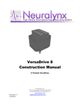
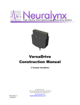
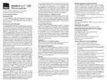
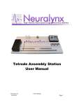
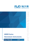
VersaDrive 8 Optical Construction Manual 8 Tetrode VersaDrive Neuralynx, Inc. 105 Commercial Drive, Bozeman, MT 59715 Phone 406.585.4542 • Fax 866.585.1743 www.Neuralynx.com Revision 1.0 10/8/2012 [email protected] Document Revision History 10/03/2012 Revision 1.0 Initial Creation VersaDrive 8 Optical Manual Expansion The VersaDrive 8 Optical is a modification of the original VersaDrive 8. Thus, the construction of the VersaDrive 8Optical is very similar to that of the VersaDrive 8. This document is designed to pair with the VersaDrive 8 manual to describe the extra steps necessary to build a VersaDrive 8 Optical. This document references figures and sections in the VersaDrive 8 manual with additions and changes. Please note these figure and section numbers in Bold refer to sections and figures in the VersaDrive 8 manual, not this document. Figures in this document that are labeled with letters are exclusive to this document. Please review all of these changes in conjunction with the VersaDrive 8 manual before beginning assembly of the drive Important Note: Below is a rendering of a ferrule based fiber implant. These can be obtained from companies such as Doric Lens, Thorlabs, or they can be made in the lab with special equipment. They are NOT included in the VersaDrive 8 Optical Kit. The minimum length for the fiber extending from the bottom of the ferrule is 15mm. At this length the tip of the fiber will recess into the base when the optical shuttle is fully raised. The diameter of the hole in the base for the fiber to pass through is 0.3mm. Figure A – An example of an Ferrule-based fiber Note: The polymicro tubing shipped with this drive has an OD of 165m and an ID of 100m. Tetrodes were loaded successfully using 12m NiCr wire. This is not the only type of wire that can be utilized. If using a different wire, check that it will work with the polymicro tubing provided prior to construction. 3. Parts list for 8 tetrode VersaDrives – In addition to the parts list in the VersaDrive 8 manual, the VersaDrive 8 Optical also includes an optical shuttle (included) and a ferrule based fiber of the user’s preference (NOT included). Additionally there are 2 additional insect pins and 1 extra drive screw for the Optical Shuttle. Figure B shows renderings of (left to right) the cap, housing, base, and optical shuttle. Neuralynx, Inc. 105 Commercial Drive, Bozeman, MT 59715 Phone 406.585.4542 • Fax 866.585.1743 www.Neuralynx.com Revision 1.0 10/8/2012 [email protected] Page 2 Figure B. Left to Right VersaDrive 8 Cap, Housing, Base, and Optical Shuttle. 5. Assembling the tetrode carriers – (5.2 Assembling the Optical Shuttle). The optical shuttle is form-fitted to accept a 1.25mm ferrule-based fiber. The ferrule-based fiber can be obtained preassembled from several companies including Thorlabs and Doric Lenses. They can also be assembled in the lab with the proper equipment. This shuttle is designed to accept a 1.25mm ferrule with the fiber of the users choice (The diameter of the hole for the fiber to pass through in the base is 0.3mm, some fibers will need to be stripped to fit in this hole including some 200m fibers). The figure below shows how to insert the ferrule-based fiber into the shuttle. A few drops of gel superglue are recommended to keep the ferrule in place in the optical shuttle. The completed optical shuttle is on the right. Figure C- Assembly of the optical shuttle Figure 1.2 – Note when comparing the VersaDrive 8 and the VersaDrive 8 Optical shuttle, the tetrode shuttles on the sides of the drive are separated by a gap for the VersaDrive 8 optical shuttle to fit in-between. Figure D is an overhead view of the optical shuttle in the middle flanked by four tetrode shuttles on the top and four on the bottom. Neuralynx, Inc. 105 Commercial Drive, Bozeman, MT 59715 Phone 406.585.4542 • Fax 866.585.1743 www.Neuralynx.com Revision 1.0 10/8/2012 [email protected] Page 3 Figure D – Overhead view of the VersaDrive 8 shuttles. Figure 2.7 and Figure 2.8 – Inserting the optical shuttle. This should be done between Figure 2.7 and Figure 2.8. The assembled optical shuttle/fiber should be run through the center hole of the VersaDrive 8 Optical Tip. The insect pin guide rails should be inserted from the bottom of the base just like the tetrode shuttles (see figure 4). Figure E – Inserting the optical Shuttle. Figure 2.8 – Insert the optical shuttle screw. This is done the same as the tetrode shuttles. Warning: When inserting the optical shuttle and raising this shuttle, be careful. The optical shuttle screw has no barrier around the head of the screw. It is very easy to slide the screwdriver off of the head off the screw and damage a polymicro tube. Figure 2.9 Raise the optical shuttle and then lower it. If the optical shuttle is raised it may get in the way of loading tetrodes. Neuralynx, Inc. 105 Commercial Drive, Bozeman, MT 59715 Phone 406.585.4542 • Fax 866.585.1743 www.Neuralynx.com Revision 1.0 10/8/2012 [email protected] Page 4 There are no further steps exclusive to the Optical Shuttle. However, before the drive is implanted ensure that the shuttle is fully raised to allow downward travel after implantation. Figure F - Above is an example of connecting a completed VersaDrive 8 Optical to an optical cable terminated with a 1.25mm ferrule and a zircon sleeve. It is recommended to put more of the zircon sleeve onto the cable than on the implant as the sleeves can be very tight fitting and hard to remove. Additionally, it is recommended to cover the end of the optical implant while not attached to a fiber as the polished end can and will be damaged if left exposed. Neuralynx, Inc. 105 Commercial Drive, Bozeman, MT 59715 Phone 406.585.4542 • Fax 866.585.1743 www.Neuralynx.com Revision 1.0 10/8/2012 [email protected] Page 5 VersaDrive 8 Construction Manual 8 Tetrode VersaDrive Neuralynx, Inc. 105 Commercial Drive, Bozeman, MT 59715 Phone 406.585.4542 • Fax 866.585.1743 www.Neuralynx.com Revision 1.0 10/8/2012 [email protected] Page 6 Contents 1. 2. 3. 4. 5. 6. 7. 8. 9. Introduction to VersaDrive Designs……………………………………….... 3 Organization of the Manual………………………………………………… 4 Parts list for 8 tetrode VersaDrives…………………………………………. 5 Description of the 8 tetrode VersaDrive….…………………………………. 6 Assembling the tetrode carriers………..……………………………………. 7 Figure 1.1 Tetrode carrier parts Figure 1.2 Inserting the tetrode guide tubes Figure 1.3 Arrangement of guide tubes and shuttles Figure 1.4 Gluing a guide tube to a shuttle Assembling the lower stage………………………………………………….. 12 Figure 2.1 Top view of the base Figure 2.2 Bottom view of the base Figure 2.3 View of the enclosure Figure 2.4 Diagram of an entire tetrode drive Figure 2.5 Inserting a tetrode carrier into the base Figure 2.6 Adding a drive pin to the first tetrode carrier Figure 2.7 Placement of the 8 tetrode carriers Figure 2.8 Attaching the enclosure Figure 2.9 Inserting 1 of the drive screws Figure 2.10 Raising a carrier to facilitate tetrode loading Figure 2.11 Lower stage ready for tetrode loading Figure 2.12 After loading one tetrode Assembling the connector…….…………………………………………….. 24 Figure 3.1 Top view of Cap Figure 3.2 Bottom view of Cap Figure 3.3 Clipping an electrical receptacle Figure 3.4 Inserting ground wires from below Figure 3.5 Securing ground wires with receptacles Figure 3.6 Insertion of wires of 1 tetrode into cap Figure 3.7 Top view of pin-out for implant connector Figure 3.8 Attaching the cap to the lower stage Figure 3.9 Lowering a tetrode carrier to allow slack in the wires Figure 3.10 Stripping and connecting wires with receptacles Figure 3.11 Inserting the inner pins and clipping all pins Figure 3.12 Raising the tetrode carriers to their ready-to-go position The 8 tetrode VersaDrive…………………………………………………….. 35 Figure 4.1 A finished 8 tetrode VersaDrive Glossary……………………………………………………………………… 37 Neuralynx, Inc. 105 Commercial Drive, Bozeman, MT 59715 Phone 406.585.4542 • Fax 866.585.1743 www.Neuralynx.com Revision 1.0 10/8/2012 [email protected] Page 7 VersaDrive Overview VersaDrives are small animal implants useful in a wide range of neuroscientific work. In their simplest embodiment, VersaDrives are designed for tetrode recordings from a single brain structure or from two or more structures that fall on one line that extends from the skull surface into the depths of the brain. Even this first type, however, has variants: Versa Drives with 4 and 8 independently moveable tetrode drives are available. In more complex cases, the tetrode exit holes for VersaDrives are arranged to target brain structures whose locations are not co-linear. Examples include implants aimed at two portions of medial entorhinal cortex plus the dorsal hippocampus and implants that allow bilaterally symmetric placement of tetrodes into the anterior thalamic nuclei. Different numbers of tetrodes are also possible for these more elaborate drives. VersaDrives can be used for electrical brain stimulation and for liquid injections as well as recordings. For instance, injections can be made into a recorded structure without disturbing the activity of identified single cells. A separate implant class allows infrared diffuse optical tomography, enabling simultaneous measurements of oxyhemoglobin and deoxyhemoglobin in freely moving rats; such measurements can be combined with EEG recordings with currently available models. We also anticipate models that allow fiber optic bundles to be placed in brain areas previously modified to express channel rhodopsin, opening up new ways to activate or suppress activity. In short, VersaDrives are versatile and new designs can be realized based on the requirements of individual investigators. Nevertheless, the job of constructing actual implants from the supplied components is quite simple. This manual contains a detailed description of the process by which the 8 tetrode VersaDrive is assembled and is likely to be sufficient to get the job done. If, however, more help is needed, please write to: [email protected] and we will work with you to solve the problem. Neuralynx, Inc. 105 Commercial Drive, Bozeman, MT 59715 Phone 406.585.4542 • Fax 866.585.1743 www.Neuralynx.com Revision 1.0 10/8/2012 [email protected] Page 8 Organization of the manual The purpose of this manual is to help you assemble and load 8 tetrode VersaDrives. The manual is divided into 5 sections. It starts with a parts list with pictures and names of the drive components. Next you will see how to put together tetrode carriers which are the subassemblies that hold the recording tetrodes and allow them to be moved gradually into the brain. In the third section, the carriers are installed in the lower stage of the VersaDrive. The lower stage is composed of the base, the enclosure, 8 of 16 drive pins that hold the shuttle carriers in place and 8 drive screws. When this installation is complete, the tetrodes can be loaded into their carriers. Fourth, the tetrode wires are threaded through the cap, the receptacles (electrical connector contacts) are pushed into the cap and the cap is attached to the lower stage with the first set of pins and a second pin set so that the entire implant is locked together. Finally, the pins and tetrodes are trimmed and the implant is stored for use during surgery. In preparation for beginning the assembly process, the user should look at the parts list on page 5 and become familiar with the overview presented on page 6. The figures that make up most of the manual are meant to be reasonably self-explanatory so that the text for each step during construction is rather brief. In our experience with how people learn to build the 8 tetrode implants, you should not be surprised if you have problems with the first one or two. Nevertheless, the learning curve is not very steep, and after some practice, it should take less than 4 or 5 hours to make a single implant. You will also find that the time per implant is reduced if you build several together. Document Revision History 3/24/2011 8/4/2011 Revision 1.0 Revision 1.1 4/23/2012 Revision 2.0 7/30/2012 Revision 2.1 Initial Creation Add comment stating that tetrodes are not included with the with the purchase of a VersaDrive. Changed Receptacles to reflect new version and added text for bending the tops of the 4 corner insect pins to better anchor the cap to the drive. Included a corrected weight and included an emery board in the kit. Neuralynx, Inc. 105 Commercial Drive, Bozeman, MT 59715 Phone 406.585.4542 • Fax 866.585.1743 www.Neuralynx.com Revision 1.0 10/8/2012 [email protected] Page 9 *Tetrodes not included Emery board (nail file) for sanding parts. Neuralynx, Inc. 105 Commercial Drive, Bozeman, MT 59715 Phone 406.585.4542 • Fax 866.585.1743 www.Neuralynx.com Revision 1.0 10/8/2012 [email protected] Page 10 Description of the 8 tetrode VersaDrive The main components of the implant are the base, the enclosure and the cap. The base is the part mounted directly on the rat’s head, above the trephine hole that admits the tetrodes into the brain. The tetrodes (and possibly portions of the guide tubes, depending on how long you decide the tubes should be) extend through small exit holes in the bottom of the base and can be gradually lowered into the brain by turning the drive screws. The enclosure surrounds and protects all working parts of the implant and provides much of the structural strength of the completed device. The cap also strengthens the implant, but its main functions are to provide access to the drive screws and to form the connector by which electrical contacts are made between the tetrodes and grounds and the outside world. The drives in a VersaDrive are independently moveable. Each drive consists of a shuttle, a guide tube, 2 drive pins, a drive screw and a tetrode. In use, the shuttle rides down the drive pins as it is pushed by the drive screw. The pins ensure that the shuttle and guide tube move down and are not twisted by the screw motion. The drive pins serve a second, equally important purpose, namely, to help clamp together the main components; thus, the drive pins are also structural components. Note that in a VersaDrive 8 there are 4 other pins near the edges of the assembly that are purely structural. Neuralynx, Inc. 105 Commercial Drive, Bozeman, MT 59715 Phone 406.585.4542 • Fax 866.585.1743 www.Neuralynx.com Revision 1.0 10/8/2012 [email protected] Page 11 Part 1 Assembling the tetrode carriers The first step in making a VersaDrive 8 is to build the tetrode carriers, each of which moves a single tetrode down into the brain from its initial implanted position. Each tetrode carrier consists of a shuttle and a guide tube, and each is a major component of one of the individually moveable drives. In the simplest configuration, all of the guide tubes are the same length, perhaps because each of the tetrodes is aimed at a single neural structure. Of course, you can cut different length guide tubes (and tetrodes) so that different brain areas can be targeted with a single implant, but this flexibility is not considered further. In contrast to the guide tubes, there are 2 shuttles types, namely, lateral and medial. In a finished implant, 4 shuttles of each kind are used in an arrangement detailed below. We begin by looking at each shuttle type, seen in Figure 1.1 below. The drawings to the left show the 3D shapes of a lateral and a medial shuttle. Below, 2D drawings of each type are used to label the holes Figure 1.1 Each shuttle type has 4 holes whose purposes are indicated by the labels. The movable part of a completed drive rides down on the two drive pins; the motion is caused by turning the drive screw. The essential result of turning the screw is to lower the guide tube and therefore the tetrode deeper into the brain. Note that the design allows the tetrodes to be moved up as well. Neuralynx, Inc. 105 Commercial Drive, Bozeman, MT 59715 Phone 406.585.4542 • Fax 866.585.1743 www.Neuralynx.com Revision 1.0 10/8/2012 [email protected] Page 12 Note: the 8 guide tube holes lie on a circle. This layout is natural for the default “exit hole” arrangement in the VersaDrive 8 (see Figure 2.2). The flexible guide tubes allow, however, other exit hole alignments. You can specify (for a cost) alternative plans that will be custom manufactured. In this overhead view, the tetrode guide tubes would extend mainly behind the plane of the drawing, away from you (a short portion extends in front, towards you). This asymmetry is critical to proper construction and is amplified in the next figures. Figure 1.2 This is a view of all 8 shuttles as they would appear looking down on the completed implant (with the occluding “cap” removed). The tetrode guide tubes are imagined to be pointing into the plane of the drawing. Thus, if the lower row of shuttles were rotated towards you out of the plane and the upper row rotated away from you into the plane, the guide tubes would all stick downwards. When the carriers (shuttles + guide tubes) are considered in 3D, they come in pairs as labeled in Figure 1.2. Thus, for instance, the two carriers called M2 are identical, whereas the M1’s and M2’s have mirror symmetry, as do the L1’s and L2’s. With this background, we describe the construction of tetrode carriers. Neuralynx, Inc. 105 Commercial Drive, Bozeman, MT 59715 Phone 406.585.4542 • Fax 866.585.1743 www.Neuralynx.com Revision 1.0 10/8/2012 [email protected] Page 13 Figure 1.3 Components of a tetrode carrier. This example consists of a guide tube and an oriented medial shuttle. With this orientation, you would build an M1 carrier; its type is confirmed by comparing Figures 1.2 and 1.3. The guide tube is either a length of 34 gauge (0.184 mm outer diameter) stainless steel tubing or an equal length of 0.1XX mm diameter polymicro glass tubing. The length of the tubing depends on the brain target. For example, if the tetrodes are to record from the dorsal hippocampus, the guide should be 13 - 15 mm long. The decision about which material to use should have been made at purchase time. In some cases, we will supply enough of whichever tubing type you selected and it will be up to you to cut the lengths. If you are to do the cutting, we will send a separate instruction manual. We also will supply cut lengths of the chosen guide tubing at some additional cost. Neuralynx, Inc. 105 Commercial Drive, Bozeman, MT 59715 Phone 406.585.4542 • Fax 866.585.1743 www.Neuralynx.com Revision 1.0 10/8/2012 [email protected] Page 14 Fig 1.4 Inserting the guide tubes into the shuttles. There are two issues here: what you are doing and how to do it. What you are doing is turning each of the 4 shuttle + tube pairs in Figure 1.4 into a different carrier by putting the tubes into the shuttles, as indicated. When you have done all 4, you will have made one each of the L1, L2, M1 and M2 carriers; which is which is labeled in the Figure. To make a complete set for a VersaDrive 8 you have to do the whole thing twice. How to do this operation requires two preliminary steps. First, when the shuttles are clipped from the manufacturing frame the cut attachment points will be jagged. To ensure that these protrusions do not interfere with tetrode carrier movements, they must be abraded away with the included emery board. The same board should be used to slightly roughen 2 mm of the guide tube. This is done to provide enough friction so that the tube does not slip out of the hole after insertion. To emphasize the fact that the products are not the same, Figure 1.4 shows two guide tubes being inserted from below (green arrows) and two from above (red arrows). For both types, the tubes should be pushed through so that 0.5 mm of the roughened ends wind up protruding. Neuralynx, Inc. 105 Commercial Drive, Bozeman, MT 59715 Phone 406.585.4542 • Fax 866.585.1743 www.Neuralynx.com Revision 1.0 10/8/2012 [email protected] Page 15 Figure 1.5 Diagram of the nearly finished tetrode carriers with a short length (0.5 mm) of each guide tube extending beyond the shuttle surface opposite to the side from which it was inserted. During assembly, carriers L2 and M2 will be rotated so that the guide tubes point down. Neuralynx, Inc. 105 Commercial Drive, Bozeman, MT 59715 Phone 406.585.4542 • Fax 866.585.1743 www.Neuralynx.com Revision 1.0 10/8/2012 [email protected] Page 16 Figure 1.6 Glue the guide tube to the shuttle to complete a tetrode carrier. The glue should be applied to the top of the shuttle at the guide tube hole and also (not shown) at the bottom of the guide tube hole. We recommend 5 minute epoxy. Super glue (cyanoacrylate) should not be used. Neuralynx, Inc. 105 Commercial Drive, Bozeman, MT 59715 Phone 406.585.4542 • Fax 866.585.1743 www.Neuralynx.com Revision 1.0 10/8/2012 [email protected] Page 17 Part 2 Assembling the lower stage Neuralynx, Inc. 105 Commercial Drive, Bozeman, MT 59715 Phone 406.585.4542 • Fax 866.585.1743 www.Neuralynx.com Revision 1.0 10/8/2012 [email protected] Page 18 Figure 2.1 Figure 2.2 Two views of the implant base. Figure 2.1 shows the base in the orientation for assembly. The upside down picture in Figure 2.2 shows the peg that is set above the trephine hole in the animal’s skull and the 8 exit holes for the guide tubes and tetrodes. Visible in both views are 16 drive pin holes and 4 structural pin holes. The drive pin holes are organized into 8 pairs; each pair is part of a single drive. Neuralynx, Inc. 105 Commercial Drive, Bozeman, MT 59715 Phone 406.585.4542 • Fax 866.585.1743 www.Neuralynx.com Revision 1.0 10/8/2012 [email protected] Page 19 Figure 2.3 View of the implant enclosure. This piece will sit above the base (Figures 2.1, 2.2) to shield the moving parts of the implant and to provide part of the support for the tetrode drives. The enclosure has 3 types of holes. The first 16 hold the tetrode drive pins; these holes line up with the holes in the base (and similar holes in the cap – see Figure 3.1 and Figure 3.2). The second set of 8 holes provides access to the heads of the drive screws. The third set of 4 holes are for the structural pins. The large rounded rectangle in the middle is for access to the drives during assembly. The screw holes are made with retainers at the bottom. The underside of the each drive screw rests on a retainer. When construction is complete, the upper side of each drive screw will be held in place by a hole in the cap. Since the hole in the cap is slightly smaller in diameter of the screw, it cannot move up or down when being turned. Thus, the retainer and the properly sized screw hole in the cap act as a sort of bearing that limits motion to rotation. Neuralynx, Inc. 105 Commercial Drive, Bozeman, MT 59715 Phone 406.585.4542 • Fax 866.585.1743 www.Neuralynx.com Revision 1.0 10/8/2012 [email protected] Page 20 Figure 2.4 Figure 2.4 shows the working parts of a single drive as if they were held in the correct supporting structure (base, enclosure, cap). During use, when the screw turns, the shuttle is pushed downward along the pins and the rigidly coupled guide tube moves along. If a tetrode were mounted in the tube, its tip would also move down, into the brain. With the 1 mm diameter screw, one complete turn pushes the moveable parts down by 0.25 mm (250 µm). The maximum practical travel of the moveable parts from initial to bottom-most position is 4.0 mm. Neuralynx, Inc. 105 Commercial Drive, Bozeman, MT 59715 Phone 406.585.4542 • Fax 866.585.1743 www.Neuralynx.com Revision 1.0 10/8/2012 [email protected] Page 21 Figure 2.5 Insertion of drive pins into drive holes in the base. The pairs of pins for two holes have been pushed into position. The pins will pushed further in the indicated direction later on, but the precise distance is not critical since the top (sharp tip) will be clipped off at the end of construction and the bottom will be bent in such a way to help anchor the implant in the dental cement. Neuralynx, Inc. 105 Commercial Drive, Bozeman, MT 59715 Phone 406.585.4542 • Fax 866.585.1743 www.Neuralynx.com Revision 1.0 10/8/2012 [email protected] Page 22 L1 M1 Figure 2.6 Here, two tetrode carriers have been placed onto their drive pins. The view in Figure 2.6 was selected to make obvious the correspondence between the guide tube of each carrier and the correct exit hole; in this view, the 2 pins for each drive are the oval-ish gray objects on the shuttles. Note that in this drawing the guide tubes take a curved path from the shuttle to the exit hole. Neuralynx, Inc. 105 Commercial Drive, Bozeman, MT 59715 Phone 406.585.4542 • Fax 866.585.1743 www.Neuralynx.com Revision 1.0 10/8/2012 [email protected] Page 23 Figure 2.7 The base with all 8 tetrode carriers in position. In addition to the drive pin pairs, the 4 structural pins have been inserted in the outermost holes. The enclosure will be added next. Neuralynx, Inc. 105 Commercial Drive, Bozeman, MT 59715 Phone 406.585.4542 • Fax 866.585.1743 www.Neuralynx.com Revision 1.0 10/8/2012 [email protected] Page 24 Figure 2.7 Lowering the enclosure onto the partly assembled drives. In this and subsequent Figures the front of the enclosure is cut away to show the state of affairs inside the implant. Neuralynx, Inc. 105 Commercial Drive, Bozeman, MT 59715 Phone 406.585.4542 • Fax 866.585.1743 www.Neuralynx.com Revision 1.0 10/8/2012 [email protected] Page 25 To enhance visualization of drive screw insertion, the pin pairs for two drives are drawn as outlines; the same is true of the front-most and rear-most structural pins. Figure 2.8 Building a drive. Insert one of the supplied 1 mm by 5 mm machine screws into a drive screw hole in the enclosure and turn down until its tip enters the drive screw hole in the shuttle of a tetrode carrier. To get the proper alignment for threading, it may be necessary to adjust the position of the tetrode carrier shuttle by manipulating the outer drive pin. If you continue to press on the screwdriver while turning, the screw will tap a thread in the shuttle hole. Additional turning will cause the tetrode carrier to rise inside the enclosure. Continue to turn until the top of the shuttle is just flush against the undersurface of the enclosure’s top. Now, repeat screw insertion for each of the other 3 drives. This step accomplishes two things. First, it brings the guide tube tops to just below the top of the enclosure, making it convenient to load the tetrodes into the tubes. Second, it puts the tetrode carriers into “what would be” the correct starting positions to lower the tetrodes into the brain. “What would be”? Yes! In later steps, the carriers will be lowered to their bottom-most positions (during insertion of the receptacles) and finally raised back to their highest positions (for actual use). Neuralynx, Inc. 105 Commercial Drive, Bozeman, MT 59715 Phone 406.585.4542 • Fax 866.585.1743 www.Neuralynx.com Revision 1.0 10/8/2012 [email protected] Page 26 Figure 2.9 A tetrode carrier in the process of being raised by its drive screw into its upper position. This elevated position brings the guide tube into the rounded rectangular window in the middle of the enclosure where it is easy to load with the tetrode. Neuralynx, Inc. 105 Commercial Drive, Bozeman, MT 59715 Phone 406.585.4542 • Fax 866.585.1743 www.Neuralynx.com Revision 1.0 10/8/2012 [email protected] Page 27 Figure 2.10 Implant ready for inserting the tetrodes into the guide tubes of the carriers. The tetrodes are prepared according to instructions in a separate manual or according to procedures used in your laboratory. Note the exposed tops of two tetrode guide tubes which are visible through the opening in the enclosure. As mentioned in Figure 2.10, their position at the top of the enclosure makes it easier to load the tetrodes. Neuralynx, Inc. 105 Commercial Drive, Bozeman, MT 59715 Phone 406.585.4542 • Fax 866.585.1743 www.Neuralynx.com Revision 1.0 10/8/2012 [email protected] Page 28 Figure 2.12 Implant with one tetrode threaded through its guide tube. To arrive at this state, the twisted portion of the first tetrode is inserted into the top of a guide tube and pushed down until the free (i.e., non-twisted) portions of the 4 tetrode wires are at the upper opening of the guide tube. When this is done, the twisted end of the tetrode will (of course) extend out of the exit hole at the bottom of the peg. Next, use super glue (cyanoacrylate) to bond the tetrode into the guide tube opening. This completes the mounting of the first tetrode. The same steps are repeated for the other 7 tetrodes. This completes construction of the lower stage. Neuralynx, Inc. 105 Commercial Drive, Bozeman, MT 59715 Phone 406.585.4542 • Fax 866.585.1743 www.Neuralynx.com Revision 1.0 10/8/2012 [email protected] Page 29 Part 3 Assembling the Connector Neuralynx, Inc. 105 Commercial Drive, Bozeman, MT 59715 Phone 406.585.4542 • Fax 866.585.1743 www.Neuralynx.com Revision 1.0 10/8/2012 [email protected] Page 30 Figure 3.1 Figure 3.2 Top (Figure 3.1) and bottom (Figure 3.2) views of the implant cap. The 36 holes in the center ridge will form the electrical connector when the 4 ground wires and 32 tetrode wires are in the holes and the receptacles are forced in to secure the wires. In the top view, 4 drive screw holes and 4 pin hole pairs are seen in front of the ridge; in the bottom view, all the holes are visible. As stated in the legend to Figure 2.3 the screw holes are slightly smaller in diameter than the screw caps, forming part of a bearing that allows rotation but not up or down screw movements. Neuralynx, Inc. 105 Commercial Drive, Bozeman, MT 59715 Phone 406.585.4542 • Fax 866.585.1743 www.Neuralynx.com Revision 1.0 10/8/2012 [email protected] Page 31 Figure 3.3 Figure 3.4 Installing ground wires. In Figure 3.3, 4 ground wires with the insulation stripped from their ends are inserted from the bottom into the middle 4 receptacle holes of the cap.. In Figure 3.4, 4 gold-colored receptacles are shown poised above the cap. The receptacles are about to be forced into the holes, thus locking the wires into place. Neuralynx, Inc. 105 Commercial Drive, Bozeman, MT 59715 Phone 406.585.4542 • Fax 866.585.1743 www.Neuralynx.com Revision 1.0 10/8/2012 [email protected] Page 32 Figure 3.5 Wiring the cap. With the ground wires in place (only 2 shown here), the next step is to send the wires from each tetrode through the proper holes in the cap. Figure 3.5 shows how the wires from one tetrode were put into 4 adjacent cap holes using very fine forceps. Also shown is a second tetrode whose wires have not yet been put into the cap holes. To complete this step, the wires from this and the other 6 tetrodes are placed into the correct cap holes. Neuralynx, Inc. 105 Commercial Drive, Bozeman, MT 59715 Phone 406.585.4542 • Fax 866.585.1743 www.Neuralynx.com Revision 1.0 10/8/2012 [email protected] Page 33 Figure 3.6 Pin connections for an 8 tetrode VersaDrive. This is a top view of the cap “ridge” showing the 36 holes into which receptacles are press-fit. The 8 tetrodes are labeled 1, 2, 3, …, 8 where each has the suffixes A, B, C and D. G1, G2, G3 and G4 are ground connection. The pin connections shown in Figure 3.7 are appropriate for use with 2 Neuralynx HS-18-CNR-MM connectors. If you are using a different connector, you must reorganize the pin-out appropriately. A little more detail about the pin arrangement. As you see, there are 4 rows of 9 pins. The center–to-center distance between any two holes along a row (e.g., between 1A and 1B) is 1.27 mm; this is standard Mill-Max spacing. In addition, the 4 rows are organized in 2 pairs. The distance between adjacent holes within a pair (e.g., between 1A and 3A) is also 1.27 mm (again from Mill-Max). Finally, the nearest-neighbor separation between a medial hole in one row-pair and the other row-pair (e.g., between 3A and 5A) is 2.73 mm. Note that any of these dimensions can be customized for your needs. Neuralynx, Inc. 105 Commercial Drive, Bozeman, MT 59715 Phone 406.585.4542 • Fax 866.585.1743 www.Neuralynx.com Revision 1.0 10/8/2012 [email protected] Page 34 Figure 3.7 Installing the cap. With the tetrode wires running through the connector holes in the cap, position the cap over the 16 + 4 pins protruding from the lower stage; the correct holes in the cap should line up with the tips of the drive pins. Push the cap down until it touches the enclosure. Neuralynx, Inc. 105 Commercial Drive, Bozeman, MT 59715 Phone 406.585.4542 • Fax 866.585.1743 www.Neuralynx.com Revision 1.0 10/8/2012 [email protected] Page 35 Figure 3.8 Slackening the tetrode wires. This step requires a bit of explanation. If the tetrode wires were captured in their holes when the tetrode carriers were in their upper-most position (as they would be without this step), turning the drive screws would quickly break the wires. It is therefore necessary to put slack into the wires so they remain intact while the tetrodes are driven into the brain. So, to provide slack, hold the cap in place and turn each drive screw until its tetrode carrier is at the bottom position. The process of lowering the tetrode carriers is indicated by the red arrow above the yellow shuttle on its way down. Note that this extends one of the tetrodes below the others. Neuralynx, Inc. 105 Commercial Drive, Bozeman, MT 59715 Phone 406.585.4542 • Fax 866.585.1743 www.Neuralynx.com Revision 1.0 10/8/2012 [email protected] Page 36 Figure 3.9 Completing the connector. Push a trimmed receptacle into each tetrode wire hole. The insertion of a receptacle strips the insulation from the wire, establishes the electrical contact and captures the wire in the hole. Now, if necessary, trim the wires as close to the tops of the receptacles as possible. Note that receptacle insertion may cut the wire without any need for trimming. Neuralynx, Inc. 105 Commercial Drive, Bozeman, MT 59715 Phone 406.585.4542 • Fax 866.585.1743 www.Neuralynx.com Revision 1.0 10/8/2012 [email protected] Page 37 Figure 3.10 Trimming the pins. This process is illustrated in this and the next 3 Figures. In Figure 3.10, the pins are being pushed up into position so that they can be clipped from above. The key idea is that after clipping and pushing the pins back down so that their upper ends are flush with the surface of the cap (see the front-most structural pin in Figure 3.12), just the right amount is left below the base so that the pins can be properly bent (as shown in Figure 3.13). It is useful to look at this whole sequence before starting with pin trimming. Neuralynx, Inc. 105 Commercial Drive, Bozeman, MT 59715 Phone 406.585.4542 • Fax 866.585.1743 www.Neuralynx.com Revision 1.0 10/8/2012 [email protected] Page 38 Figure 3.11 Clip the raised pins with side cutters. DO NOT CUT THE PINS ON THE ENDS OF THE ROWS. Although not currently shown in these figures, these 4 pins will be used to anchor the top of the implant. Neuralynx, Inc. 105 Commercial Drive, Bozeman, MT 59715 Phone 406.585.4542 • Fax 866.585.1743 www.Neuralynx.com Revision 1.0 10/8/2012 [email protected] Page 39 Figure 3.12 Push the cut ends of the pins down so they are flush with the top of the implant cap. This has been done for the front-most structural pin. DO NOT DO THIS FOR THE CORNER PINS. Neuralynx, Inc. 105 Commercial Drive, Bozeman, MT 59715 Phone 406.585.4542 • Fax 866.585.1743 www.Neuralynx.com Revision 1.0 10/8/2012 [email protected] Page 40 Figure 3.13 As the last step in dealing with the pins, bend them so that the bottom ball is against the underside of the base. FOR THE 4 CORNER PINS, ALSO BEND THEM AT THE TOP OF THE DRIVE TO ANCHOR THE TOP OF THE IMPLANT FIRMLY INTO PLACE. If the pins were pushed up by the right amount and then clipped, the bottom ball should end so that it is just invisible from the top of the nearly complete implant. Why are the pins bent in the indicated manner? They turn out to provide excellent anchors for the dental cement that locks the implant to the skull screws you insert during surgery. If there are reasons to bring the implant a bit closer to the skull, the pins may of course be cut flush with the bottom of the base instead of being bent. An implant treated in the second manner is shown on the cover page of this manual; a finished implant with bent pins is shown in Figure 4.1. Neuralynx, Inc. 105 Commercial Drive, Bozeman, MT 59715 Phone 406.585.4542 • Fax 866.585.1743 www.Neuralynx.com Revision 1.0 10/8/2012 [email protected] Page 41 Figure 3.13 As described above, it is now necessary to re-raise the drives back to their uppermost position, from which they will be lowered into the brain. Figure 3.11 shows one of the drives on its way back up. Of course, re-raising must be done for the other drives as well. The final task, not shown explicitly, is to trim the tetrodes to the length you will require to reach the brain structure of interest for your purposes. In the completed drive drawn in the last diagram (Figure 4.1) the tetrodes have been clipped to a (scaled) length that is about correct for an initial position above the CA1 layer of the dorsal hippocampus, assuming use of the stereotaxic system of Paxinos and Watson (6th Edition, 2005, Elsevier Academic Press). Neuralynx, Inc. 105 Commercial Drive, Bozeman, MT 59715 Phone 406.585.4542 • Fax 866.585.1743 www.Neuralynx.com Revision 1.0 10/8/2012 [email protected] Page 42 Part 4 A complete 8 tetrode VersaDrive Neuralynx, Inc. 105 Commercial Drive, Bozeman, MT 59715 Phone 406.585.4542 • Fax 866.585.1743 www.Neuralynx.com Revision 1.0 10/8/2012 [email protected] Page 43 Figure 4.1 Drawing of an 8 tetrode VersaDrive ready to be put on the head of a rat, a mouse or another small animal. The drive weighs ~3.2 grams fully assembled and according to past experience is easily carried by s a mouse. This model and ones with different exit hole arrangements (see Figure 2.2) allow stable, low noise recordings from one or more brain structures. We hope that this manual made the job of putting together your first drive reasonably easy, but if some of the steps are unclear, please write to us and we will try to provide additional explanations. Of course, if there are errors or problems in the current manual we will make appropriate modifications in future versions. Neuralynx, Inc. 105 Commercial Drive, Bozeman, MT 59715 Phone 406.585.4542 • Fax 866.585.1743 www.Neuralynx.com Revision 1.0 10/8/2012 [email protected] Page 44 Glossary Base: Cap: Drive: Drive Pins Drive Screw: Enclosure: Exit Hole: Guide Tube: Lower Stage: Ridge: Peg: Receptacles: Shuttle: Tetrode: Bottom-most of three structural implant parts; the others are the “enclosure” and the “cap”. The lowest part of the base is the “peg” which is located above the trephine hole via which tetrodes enter the brain. Top-most of three structural implant parts; the others are the base and the enclosure. The cap helps to support the drives. At the top of the middle “ridge” are holes properly spaced to form a standard Mill-Max connector when filled with receptacles. The working subassembly of an implant. Each independently movable drive carries a tetrode into the brain. A drive consists of a tetrode carrier, a drive screw and two drive pins. Drive components and their arrangement are depicted in Figure 2.4. Rails on which tetrode carriers move down, pushing the tetrode into the brain. Each drive has 2 pins, set up a pairs. Captive screw whose bottom inserts into a hole in a shuttle. Turning the screw drives a tetrode carrier and therefore a tetrode into the brain. The pitch of the 1.0 mm screws used in VersaDrives is 0.250 mm per turn. Middle of three structural implant parts; the others are the “base” and the “cap”. The enclosure shields the moving parts of the drives from external forces. The small hole at the bottom of the peg through which a tetrode leaves the drive and enters the brain. A Polymicro Glass tube that guides a tetrode from its top, above a shuttle, into an exit hole at the bottom of the base. Guide tubes may also be made of stainless steel hypodermic tubing. Subassembly that consists of the base, enclosure, outer drive pins and drive screws. Part 2 is devoted to describing its construction. Center portion of the cap that forms the electrical connector. The bottom of the base. The peg is a contoured cone that aims the tetrodes properly to enter the trephine hole in the rat’s skull. The exit holes are drilled through the peg. Electrical contact pins trimmed of their tails. When forced into a connector hole, the receptacle strips a tetrode wire and secures the wire in place. Moveable part that slides down drive pins by screw motion. Each shuttle holds a guide tube, inside of which sits a tetrode. 4 wire probe used to record multiple individual neurons, notably from the brains of freely moving rats and mice. Tetrodes are not included with the VersaDrives. Neuralynx, Inc. 105 Commercial Drive, Bozeman, MT 59715 Phone 406.585.4542 • Fax 866.585.1743 www.Neuralynx.com Revision 1.0 10/8/2012 [email protected] Page 45 Tetrode Carrier: Subassembly that consists of a “shuttle” and a “guide tube”. Tetrode carriers are driven down inside the enclosure by screw motion, pushing the tetrodes into the brain. Neuralynx, Inc. 105 Commercial Drive, Bozeman, MT 59715 Phone 406.585.4542 • Fax 866.585.1743 www.Neuralynx.com Revision 1.0 10/8/2012 [email protected] Page 46