1
Low Voltage Power & Insulated Case Circuit Breakers
Section 8
Low Voltage Power and DC Circuit Breakers
Insulated Case Circuit Breakers
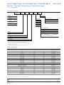
EntelliGuard™ G Low Voltage Power Circuit Breakers ...........8-2
Overview and Functions ........................................................................8-2
EntelliGuard™ TU Trip Units....................................................................8-4
Product Nomenclature ............................................................................8-5
Cassettes Nomenclature......................................................................8-11
Accessories.................................................................................................8-13
WavePro Circuit Breakers with EntelliGuard™ TU,
Power+, Enhanced MicroVersaTrip™ Plus and
MicroVersaTrip™ PM Trip Unit Systems ............................8-24
WavePro Low Voltage Power Circuit Breakers .....................8-26
OEM Substructures and Substructure Accessories .............8-40
Trip Units......................................................................................8-49
Overview – EntelliGuard™ TU, Power+ and
Enhanced MicroVersaTrip™ .............................................................8-49
Product Number Nomenclature System ......................................8-55
Trip Unit Conversion Kits Introduction...................................8-66
Overview – EntelliGuard™ TU, and
MicroVersaTrip™ PM Conversion Kits...........................................8-67
Remanufactured MVT Trip Unit
Overview and Features......................................................................8-69
ProTrip™ Trip Unit Conversion Kits Selection Guide.................8-70
ProTrip™ Rating Plugs.............................................................................8-74
EntelliGuard™ TU Trip Unit Conversion
Kits Selection Guide.............................................................................8-76
EntelliGuard™ TU Trip Rating Plugs..................................................8-80
EntelliGuard™ TU Trip Unit Conversion Kit
Accessories and Hardware ..............................................................8-81
Trip Unit Accessories..............................................................................8-83
Asbestos Free Arc Quencher Replacement Kits ...................8-85
Gerapid High Speed DC Circuit Breakers...............................8-86
Features and Benefits ...........................................................................8-86
Technical Data ..........................................................................................8-88
Outline Drawings and Dimensions..................................................8-89
Power Break™ II ...........................................................................8-91
Features .......................................................................................................8-91
Construction Options .............................................................................8-92
EntelliGuard™ TU Trip Unit Features................................................8-93
Power+ Trip Unit Features...................................................................8-94
Enhanced MicroVersaTrip™ Trip Unit Features ..........................8-95
Trip Unit Characteristics .......................................................................8-96
Power Break™ II Nomenclature System ........................................8-99
Product Number Nomenclature System ...................................8-104
Interrupting Capacity and Withstand Ratings ........................8-108
How to Order...........................................................................................8-109
Frame Selection (Old Structure) .....................................................8-110
Trip Unit Selection.................................................................................8-111
Enhanced MicroVersaTrip™ Rating Plug Selection ................8-113
Stationary and Draw-out Switch Selection ..............................8-114
Stationary and Draw-out Breaker Accessories ......................8-115
Stationary Breaker Mounting Kits .................................................8-121
Stationary Breaker Mounting Kits,
Wall Mounted Enclosures, Floor Mounted Enclosures .....8-122
Neutral Current Sensors and
POWER LEADER™ Accessories......................................................8-123
Draw-out Breaker Accessories.......................................................8-124
Reference Publications............................................................8-126
Visit GE Industrial Solutions website for ordering low voltage power and insulated case circuit breakers and accessories at:
www.geindustrial.com/industrialsystems/wizards/peb_oem_am/home.htm
Rev. 11/13
Data subject to change
without notice
www.geindustrial.com
BuyLog™ Catalog
8-1
Low Voltage Power & Insulated Case Circuit Breakers
Section 8
™
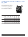
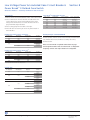
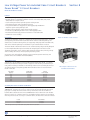
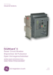
EntelliGuard G Low Voltage Power Circuit Breaker
Overview and Functions
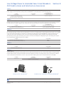
EntelliGuard™ G Circuit Breakers
EntelliGuard™ G Circuit Breakers are the newest top of the line
circuit breakers designed to meet the demands of today’s
electrical distribution systems by providing ultimate system
performance without sacrificing safety or reliability. EntelliGuard™
G devices are available in standard, 100% rated, ANSI/UL1066,
UL489 and IEC ratings. Breakers are offered to OEMs in 3 and 4
pole designs from 400A to 6000A (UL/ANSI) or up to 6300A (IEC)
with fault interruption ratings up to 150kA and many fieldinstallable accessories. EntelliGuard™ G 3-pole breakers are the
standard in GE AKD-20 Low Voltage Switchgear suitable for
280Vac and 600Vac. The breakers are suitable for 280Vac,
480Vac and 600Vac applications, and they provide advanced
circuit protection, limit arc fault energy and preserve system
coordination without sacrificing any of these critical functions.
Standard Functions
The EntelliGuard™ G Circuit Breakers offer operational safety with
functions such as:
Closing and opening - can be initiated remotely or via the front
cover push buttons. An Open-Close-Open cycle is possible without recharging.
Breaker/Main Contact Status - OPEN/CLOSED, ON/OFF indication
is provided on the front cover.
Through-Door Racking - The breaker racking mechanism is
accessible through the front door and permits safely disconnecting/withdrawing the circuit breaker without opening the door and
exposing personnel to live parts during the process.
Two-Step Stored Energy Mechanism - Breaker operates via
stored energy mechanisms that can be manually charged (MO) or
electrically charged (EO) by the Spring Charging Motor. Closing
time is less than five cycles.
Ready to Close Indicator - Provides visible indication/readiness
for close operation.
Reverse Feed – EntelliGuard™ G devices can be fed from top or
bottom terminals.
Breaker Status Indicators - Standard Indicators include:
—The breaker status indicator shows the condition of the main
contacts (OPEN, CLOSED).
—The status of the closing springs is indicated as CHARGED
or DISCHARGED.
—The draw-out position indicator displays whether the breaker is
in the CONNECT, TEST or DISCONNECT position.
—The breaker also includes a switch that provides main
contact status indication to the POWER LEADER™ Power
Management System.
—The optional Reduced Energy Let-Through (RELT) is provided
with an ON/OFF contact closure to positively indicate whether
the RELT setting is enabled or not.
Coils - EntelliGuard™ G devices have provisions for four accessory
operating coils. The four positions can be filled by the following
four devices: one Close Coil (CC or CCC), one Shunt Trip Coil, one
UVR (Under Voltage Release), and the fourth position can either
be a Shunt Trip Coil or a UVR.
Rejection Feature - A factory-installed rejection feature prevents
mismatching breakers and cassettes/substructures.
EntelliGuard™ G breakers are designed for flexibility and
superiority with functions such as:
Short Time Rating - Up to 100kA for 0.5 sec.
Short Circuit/High Interruption Rating - 150kA at 600V,
100kA at 690V.
8-2
BuyLog™ Catalog
Motor Operator Heavy Duty, Motor/Gearbox Unit easily accessible.
Interlocks - Standard interlocks include:
—Drawout Breaker
—Drawout Breaker/Main Contacts
—Spring Discharge Interlock
Padlocking Devices - The padlocking device is standard on
breakers and allows up to three padlocks with 1/4" to 3/8" diameter shanks to secure the breaker in the OPEN/TRIP FREE position.
Thermal Performance - ANSI C37 and UL 489 designs are 100%
rated up to 40ºC when applied in recommended enclosure sizes.
IEC 60947 versions are 100% rated in free air up to 50ºC. IP31
enclosure/switchboard rating is based on size, recommended up
to 50ºC ambient with rear vertical bus connection.
Field Installable Trip Units and Accessories Field - installable
accessories are common to all breaker envelopes and frames.
Optionally, accessories are also factory mountable.
www.geindustrial.com
Rev. 11/13
Data subject to change
without notice
Low Voltage Power & Insulated Case Circuit Breakers
Section 8
™
EntelliGuard G Low Voltage Power Circuit Breaker
Functions
Optional Functions
EntelliGuard™ G Circuit Breakers offer many optional functions in
order to enhance and facilitate the use of the circuit
breaker. Those functions include:
Auxiliary Switches - (Optional) Four available designs:
—Power rated (3NO+3NC)
—Power rated (3NO+3NC) + low signal (Hi-Fi) (2NO+2NC)
—Power rated (8NO+8NC)
—Power rated (4NO+4NC) + low signal (Hi-Fi) (4NO+4NC)
Key Interlock - Up to four optional key interlocks are available
(Kirk, Ronis, Profalux, Castell). Switchgear applications utilize a Kirk
key interlock mounted in the cassette. A maximum of two key
interlocks may fit in the cassette.
Mounting Straps/Accessories Kits - are available to mount and
connect fixed/stationary breakers.
Optional Lockable Shutters - are available (factory installed).
Carriage Position Switch - This optional cassette/substructure
device permits local or remote indication of the circuit breaker
status (CONNECTED, TEST, DISCONNECTED), 2NO/2NC single pole,
double throw contacts are available for each position.
Lifting Truck - Optional lifting tool with separate slings is
available for all breaker sizes.
Optional IP Covers - IP54 covers (protected against harmful
amounts of dust and splashing water) are available for all
breaker sizes.
Mechanical Counter - Provides local record of the cumulative
number of complete breaker closing operations.
Cable Interlocks - (OEM Applications Only) Available for fixed and
draw-out breakers, these units enable direct interlocking of
EntelliGuard™ G circuit breakers.
Bell Alarm Contact - Available with or without a mechanical lockout feature, the bell alarm operates when the trip unit issues a
trip command.
Rev. 11/13
Data subject to change
without notice
www.geindustrial.com
BuyLog™ Catalog
8-3
Low Voltage Power & Insulated Case Circuit Breakers
Section 8
™
EntelliGuard G Low Voltage Power Circuit Breaker
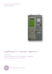
EntelliGuard™ TU Trip Units
EntelliGuard™ TU Trip Units
EntelliGuard™ TU Trip Units enable the EntelliGuard™ G circuit
breaker with advanced technology and superior circuit protection
without compromising selectivity or arc flash protection.
EntelliGuard™ TU series trip units are available as the standard
controller for new production EntelliGuard™ G ANSI/UL 1066, UL
489 and IEC circuit breakers.
These cutting edge trip units provide Zone Selective
Instantaneous Protection, Waveform capture, Reduced Energy Let
Through Instantaneous Trip and are designed to supply communications for Modbus or Profibus protocols.
Note: See page 8-49 for more information about the
EntelliGuard™ TU Trip Unit.
Accessories
There are more than 20 different types of factory or field
installed accessories available for the EntelliGuard™ G circuit
breaker. Whether it’s a bell alarm contact, key interlock or
redundant shunt trips, GE has the accessory combinations to
meet your need!
Factory-Installed Accessories
—Motor Operators
—Closing Devices
—Shunt Trip for Ground Fault
—UVR with Fixed Time Delay
—Second Shunt Trip or UV Release
—Auxiliary Switches and Contacts
—Bell Alarm and Trip Annunciation
—Bell Alarm Contact
—Trip Annunciation
—Breaker Mounted Key Interlocks
—Mechanical Interlocks- Fixed Breakers
—Mechanical Interlocks – Drawout Breakers
Accessories for Field Installation
—Carriage Position Switch
—Coil Signaling Contact Module
—Contact Wear Indicator
—Door Interlock
—Electrical Close Switch
—Lock Kits
—Lifting Truck
—Mechanical Operation Counter
—Pushbutton Padlock Device
—Ready-to-Close Switch
—Secondary Disconnect Block
—Spring Charged Contact
—UVR Time Delay Module
Note: See page 8-15 for more information about the accessories
available for EntelliGuard™ G Circuit Breakers.
8-4
BuyLog™ Catalog
www.geindustrial.com
Rev. 11/13
Data subject to change
without notice
Low Voltage Power & Insulated Case Circuit Breakers
Section 8
™
EntelliGuard G Circuit Breaker
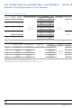
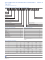
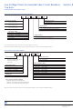
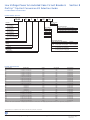
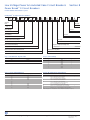
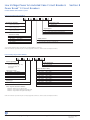
EntelliGuard™ G Circuit Breaker Nomenclature
EntelliGuard™ G Circuit Breaker Product Number Structure
Digit
G
A
1 6
M
1
H
E
R
X
5
R
A
X
X
L 4
X
6
V
1
2
3, 4
5
6
7
8
9
10
11
12
13
14
15
16, 17
18
19
20
Circuit
Breaker Family
G = EntelliGuard™ G
Breaker/Switch
Rating Plug
1900
Advanced Features and
Communications
Monitoring + Data acq.,
Modbus Protocol + RELT
Breaker Switch Type
A = ANSI/U 1066
Circuit Breaker
Current Rating/Sensors
16 = 1600A
Zone Selective Interlocking (ZSI)
None
Short Circuit Withstand Rating
Interrupting Rating Tier ANSI/UL 1066
Overcurrent Protection Ground Fault
LSIG
Mounting
M = OEM, Drawout, 3 poles
Mechanical Interlock
None DEFAULT
Spring Charge Motor
1 = AC - 120Vac
Key Interlock & Padlock Provisions
None
Closing Devices
E = Closing Coil - 110Vdc/130Vdc; 120Vac
Bell Alarm, Mechanical Counter, Trip Annunciation
Bell Alarm Contact with lockout
Auxiliary Switch, Coil Signaling Contact
CSC, Hi-Fi Via Trip Unit - 2nd ST or 2nd UVR
Shunt Trip
R = 110/125Vdc; 120Vac
Under Voltage Release (UVR)
X = None
Second Shunt Trip, Second UVR
R = Second Extended Range Shunt Trip 110/125Vdc; 120Vac
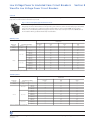
Digits 3 and 4 Current Rating / Sensor
Digit 1 Circuit Breaker Family
Device Series Line
Code
EntelliGuard™ G Breaker/Switch
Current Sensor
Rating (A)
G
Digit 2 Breaker Switch Type
Breaker/Switch Type,
Secondary Mounting
ANSI/UL1066 Circuit Breaker
UL 489 Circuit Breaker
ANSI Non-auto CB
(ANSI Switch)
UL489 Non-auto CB
(UL Switch)
Side
Envelope 1
Top
Envelope 2 & 3
Top
A
B
N
U
A
B
C
M
C
D
S
D
Top = Top Mounted Secondary Disconnects (TSD).
Side = Side Mounted Secondary Disconnects (SSD). (Available on Envelope 1 only.)
NOTE: N, U, M, S characters are for Envelope 1 only with top mounted secondary
disconnects (TSD).
When ordering codes A, B, C, D, Side Secondary Disconnects (SSD) are supplied as
standard on Envelope 1.
Codes N, U, M, S are not valid for Envelopes 2 and 3.
Envelope 1 (Type N and H, 400A - 2000A).
NOTE: DC Ratings; trip unit not included. DC Rated Circuit Breakers require external
control devices (e.g., Type 37 or Type 76 DC Relays).
NOTE: Side Secondary Disconnects are specifically intended for 5-High ("high
density") equipment designs.
With Side Mounted Disconnects (SSD), the following Aux. Switches are not valid (In
Digit 12); Auxiliary Switch, 8NO+8NC (Power Rated) or Aux. Switch, 4NO/4NC
(Power Rated) + 4NO/4NC (High Fidelity).
Rev. 11/13
Data subject to change
without notice
Digit
www.geindustrial.com
400
600
800
1000
1200
1600
2000
2500
3000
3200
4000
5000
6000
1Switches
Switches1
Circuit Breaker
ANSI
UL489
ANSI
UL489
04
–
08
–
–
16
20
–
–
32
40
50
–
04
06
08
10
12
16
20
25
30
–
40
50
60
–
–
08
–
–
16
20
–
–
32
40
50
–
–
–
08
–
12
16
20
25
30
–
40
50
60
(Digit 2 = M, S, C, D) do not have current Sensors or a trip unit
BuyLog™ Catalog
8-5
Low Voltage Power & Insulated Case Circuit Breakers
Section 8
™
EntelliGuard G Circuit Breaker
EntelliGuard™ G Circuit Breaker Nomenclature
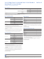
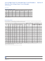
Digit 5 Short Circuit Withstand Ratings
Code
S
N
H
P2
E
M
B
L
Code
S
N
H
P2
M
L
Interrupting Rating Tier ANSI/UL1066 Devices, LVPCB
1/2S
Override
254V
580V
635V Withstand
HSIOC
No. 1
65,000
65,000
50,000
50,000
50,000
49,000
65,000
65,000
65,000
65,000
None
None
85,000
85,000
65,000
65,000
65,000
63,700
100,000
100,000 65,000
65,000
65,000
63,700
85,000
85,000
85,000
85,000
None
None
100,000
100,000 100,000
85,000
85,000
83,800
100,000
100,000 100,000
100,000
None
None
150,000
150,000 100,000
100,000
100,000
98,000
Interrupting Rating Tier UL489 Devices ICCB
1/2S
240V
480V
600V Withstand
HSIOC
65,000
65,000
50,000
42,000
42,000
65,000
65,000
65,000
42,000
42,000
85,000
85,000
65,000
50,000
50,000
100,000 100,000
65,000
50,000
50,000
100,000 100,000 100,000
65,000
65,000
150,000 150,000 100,000
85,000
85,000
Envelope 1
Override
WI
53,500
None
69,500
69,550
None
90,950
None
107,000
Code
S
N
H
P
E
M
B
L
400-1200
X
Envelope 2
400-2000
X
X
X
3200
Override
WI
44,940
44,940
53,500
53,500
69,550
90,950
Code
S
N
H
P
M
L
400-3200
3200
4000-5000
X
X
X
X
X
X
X
X
Envelope 1
Override
No. 1
N/A
N/A
N/A
N/A
N/A
N/A
Envelope 3
400-1200
X
Envelope 2
400-2000
X
X
X
Envelope 3
2500-3000 400-3000
3000
4000-6000
X
X
X
X
X
X
Close and Latch Ratings (MCR set accordingly)
UL/ANSI 1
UL/ANSI 2
UL/ANSI 3
42,000
65,000
100,000
S
42,000
IEC 1
IEC 2
IEC 3
UL/ANSI CB MCR setting determined base on Envelope only. For Retrofill's (A = 17,000, B = 33,000, N = 42,000)
N
42,000
50,000
H
42,000
50,000
M
E
65,000
100,000
65,000
L
100,000
Notes: Override has 7% pick up tolerance. Nominal setting is 98% of lcw if no other instantaneous is on, or 107% of lcw if any other instantaneous is on. UL 489 CB always
have other instantaneous protection on. MCR set at 78% Close and Latch rating with a -10% tolerance. 6000A UL 489 CB is 100% rated as stationary and 80% rated
draw-out.
ANSI Non-Automatic Switches
254V
580V
635V
42,000
42,000
42,000
65,000
65,000
65,000
100,000
100,000
100,000
30 Cycle Withstand Ratings
Code
N
M
B
UL489 Non-Automatic Switches
240V
480V
600V
42,000
42,000
42,000
65,000
65,000
65,000
150,000
150,000
100,000
30 Cycle Withstand Ratings
Code
N
M
B
Code
N
M
B
1.
Code
N
M
B
1.
Envelope 1
800-2000
X
Envelope 2
800-3200
Envelope 3
3200-5000
X
X
Envelope 1
800-2000
X
Envelope 2
800-3000
Envelope 3
3000-6000
X
X
1 Non-automatic switches are provided with no internal sensing or tripping mechanism and cannot be applied above their respective withstand levels. If non-automatic
device is required at ratings above the available switches required, it is recommended that a circuit breaker set with maximum setting be employed using external control
or protection as required by the application
2 P frame available as 3-pole only
Note: IEC Ratings are also available upon request.
UL489B Ratings Suitable for use in Photovoltaic system in accordance with article 690 of the NEC
Envelope
2
Type
M
Amps
800-3000
Short Interrupting
Current (kA)
30
Minimum
Mechanical
Endurance
12500
Rated Endurance
Minimum
Electrical
Endurance at
600Vdc
500
Minimum
Electrical
Endurance at
1000Vdc
500
Four configurations available for 600Vdc and 1000Vdc with or without isolating both DC legs.
Note: Bus Bars must be ordered separately
Time Constant (L/R) = 15msec, Rated calibration temperature 50˚C.
Note: See EntelliGuard™ G Circuit Breaker Configurator for pricing. Contact a sales representative for configurator.
8-6
BuyLog™ Catalog
www.geindustrial.com
Rev. 11/13
Data subject to change
without notice
Low Voltage Power & Insulated Case Circuit Breakers
Section 8
™
EntelliGuard G Circuit Breaker
EntelliGuard™ G Circuit Breaker Nomenclature
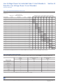
Digit 6 Mounting
Designation
Mounting
Poles
3
4, right
4, left
3
4, right
4, left
3
3
Drawout
OEM
Stationary
Drawout
Stationary
GE Equipment
Code
1
2
3
4
5
6
D
F
NOTE: Right, Left indicates the location of the fourth pole, typically used to switch the Neutral.
NOTE: 800A Envelope 2 (E, M Ratings) are not available in 4-pole design.
NOTE: P frame available as 3-pole only
Digit 7 Spring Charge Motor
Spring Charge Motor Electrically Operated (EO)
24/30Vdc
48Vdc
DC
60Vdc
72Vdc
110/130Vdc
250Vdc
48Vac
120Vac
AC
240Vac
277Vac
1
Blank/None
Digit 9 Shunt Trip
Code
A
B
C
D
E
F
G
H
J
K
X
1An
"X" (Blank/None) denotes a Manually Operated device (MO)
Spring Charge Contact, GSCC1, included with all Motor Operators.
NOTE: When a Spring Charging Motor is selected, a Closing Device must be selected
from Closing Devices for Digit 8, and a Shunt Trip Device must be selected from
Shunt Trip 1 Devices for Digit 9.
Shunt Trip 1 with a coil voltage different from the Spring Charge Motor may be userselected.
When a Motor & Spring Charge Contact is selected, the Ready To Close (RTC) (Digit
13) contact output options to the SD (Codes 1, 2, D, E, G, H, K, L) will be wired to
the Spring Charge Contact location on the Secondary Disconnect Block.
Digit 8 Closing Devices
Closing Coil Type
Closing Coil (CC)2
Command Operated
Closing Coil (CCC)3
24Vdc
30Vdc
48Vac/dc
60-72Vdc
110Vdc/130Vdc; 120Vac
208Vac
220Vdc; 240Vac
250Vdc; 277Vac
24Vdc
30Vdc
48Vac/dc
60-72 Vdc
110Vdc/130Vdc; 120Vac
208Vac
220Vdc; 240Vac
Blank/None
Code
A
B
C
D
E
F
G
H
M
N
P
Q
R
S
T
X
Extended Range Shunt Trip (ANSI/UL)4
24Vdc
48Vac/dc
70-72Vdc
110/125Vdc; 120Vac
208Vac
220Vdc; 240Vac
250Vdc; 277Vac
Blank/none
Code
M
P
Q
R
S
T
V
X
4The
Extended Range Shunt Trip is specifically intended and required for UL ANSI
Ground Fault applications. The pick up range is 55-110% of the ST coil voltage.
When a motor is selected from the Spring Charging Motor (Digit 7) a Shunt Trip must
be selected.
SELECT ONE DEVICE ONLY.
Digit 10 Under Voltage Release (UVR)
UVR with Fixed Time Delay5
Code
24Vdc
30Vdc
48Vac/dc
60-72Vdc
110/130Vdc; 120Vac
208Vac
220Vdc; 240Vac
250Vdc; 277Vac
Blank/none
1
2
3
4
5
6
7
8
X
5The
UVR Shunt Trip with Fixed Time Delay is specifically intended for applications
where a delay period ('ride-through') is required due to potential voltage events.
The design delays are 50msec when system voltage drops to 50% and 20 msec
when system voltage drops below 50%.
An optional External UVR Time Delay Module is available in a 1 - 3sec delay.
SELECT ONE DEVICE ONLY.
2The
Closing Coil (CC) permits either local or remote release of the spring charged
closing mechanism by electrical operation.
3The Command Operated Closing Coil (CCC) includes an additional anti-pumping
safety feature to ensure that the electrical closing signal must be released
before further closure is attempted, a shut off is initiated if the closing signal is
maintained.
NOTE: Manual button through breaker cover is included as standard assembly.
NOTE: When a Spring Charging Motor is selected (Digit 7), a Closing Device must be
selected from Closing Devices for Digit 8, and a Shunt Trip Device must be
selected from Shunt Trip 1 Devices for Digit 9.
SELECT ONE DEVICE ONLY.
Rev. 11/13
Data subject to change
without notice
www.geindustrial.com
BuyLog™ Catalog
8-7
Low Voltage Power & Insulated Case Circuit Breakers
Section 8
™
EntelliGuard G Circuit Breaker
EntelliGuard™ G Circuit Breaker Nomenclature
Digit 11 Second Shunt Trip, Second UVR
Type
24Vdc
30Vdc
48Vac/dc
60-72Vdc
110Vdc/130Vdc; 120Vac
208Vac
220Vdc; 240Vac
250Vdc; 277Vac
24Vdc
48Vac/dc
70-72Vdc
110/125Vdc; 120Vac
208Vac
220Vdc; 240Vac
250Vdc; 277Vac
Second UVR with Fixed
Time Delay1
Second Extended
Range Shunt Trip
(ANSI/UL)2
Blank/none
Code
1
2
3
4
5
6
7
8
M
P
Q
R
S
T
V
X
1The
UVR with Fixed Time Delay is specifically intended for applications where a delay period ('ride- through') is required due to potential voltage events. The design delays
are 50msec when system voltage drops to 50% and 20msec when system voltage drops below 50%.
2The Extended Range Shunt Trip is specifically intended and required for UL ANSI Ground Fault applications. The pickup range is 55-110% of the ST coil voltage.
An optional External UVR Time Delay Module is available in a 1 - 3 second delay.
SELECT ONE DEVICE ONLY.
Digit 12 Auxiliary Switch, Coil Signaling Contact
Contact Configuration
Auxiliary Switch, 3NO+3NC (Power Rated)3 STANDARD/INCLUDED
Auxiliary Switch, 8NO+8NC (Power Rated)4
Aux. Switch, 3NO/3NC (Power Rated) +2NO/2NC (High Fidelity)
Aux. Switch, 4NO/4NC (Power Rated) +4NO/4NC (High Fidelity)4
Auxiliary Switch, 3NO+3NC
(Power Rated)
Auxiliary Switch, 3NO/3NC (Power Rated)+2NO/2NC (High Fidelity)
Auxiliary Switch, 3NO+3NC (Power Rated)
Aux. Switch, 3NO/3NC (Power Rated) + 2NO/2N (High Fidelity)
CSC, PR, (1NO on SD) - Close Coil or CCC
CSC, Hi-Fi via Trip Unit - Close Coil or CCC5
CSC, PR, (1NO on SD) - 1st Shunt Trip
CSC,Hi-Fi via Trip Unit - 1st Shunt Trip5
CSC, PR, (1 NO on SD) - 1st UVR
CSC,Hi-Fi via Trip Unit - 1st UVR5
CSC, PR, (1NO on SD) - 2nd ST or 2nd UVR
CSC, Hi-FI via Trip Unit - 2nd ST or 2nd UVR5
CSC, PR, (1NO on SD) - All Installed Devices
CSC,HI-Fi via Trip Unit - All Installed Devices5
CSC, PR, (1NO on SD) - All Installed Devices
CSC,HI-Fi via Trip Unit - All Installed Devices5
Code
2
4
6
8
A
B
C
D
E
F
G
H
J
K
L
M
N
P
Q
R
S
T
U
V
Abbreviations
CCC = Command Operated Close Coil
CSC = Coil Signaling Contact
Hi-Fi = High Fidelity
PR = Power Rated
SD = Secondary Disconnect
NOTE: The term "Hi Fidelity" (HiFi) refers to gold-plated contacts used for signal level outputs (10mA minimum - 100mA maximum, 5-30Vdc, 125Vac)
NOTE: If no devices were selected in Digit 8, 9, 10, 11 (Codes = "X"), then Options A - V are Invalid
NOTE: Options A-V are only valid if the corresponding device to be monitored by the Coil Signaling Contact (CSC) is selected in digits 8, 9, 10, 11
3The 3NO/3NC scheme is STANDARD (INCLUDED, CODE 2) and is wired to Secondary Disconnect Block A; all other selections require Secondary Disconnect Block B
4For Side-mounted Secondary Disconnect Blocks All options are available EXCEPT options (4 and 8)
5In order to output the Coil Signaling status HiFi via trip unit (Options B, D, F, H, K, M, P, R, T, and V) a communications package must be selected in Advanced Features (Digit
19; options "2, 3, 6, 7, 8, 9") This options requires Secondary Disconnect Block B.
If a UL or ANSI Switch is selected in Digit 2 (C, D, M, S), the HiFi via Trip unit Options are not valid (Options B, D, F, H, K, M, P, R, T, and V)
Note: See EntelliGuard™ G Circuit Breaker Configurator for pricing. Contact a sales representative for configurator.
8-8
BuyLog™ Catalog
www.geindustrial.com
Rev. 11/13
Data subject to change
without notice
Low Voltage Power & Insulated Case Circuit Breakers
Section 8
™
EntelliGuard G Circuit Breaker
EntelliGuard™ G Circuit Breaker Nomenclature
Digit 13 Bell Alarm, Mechanical Counter and Trip Annunciation
Digit 15 Mechanical Interlocks
Bell Alarm, Mechanical Counter and Trip Annunciation
Code
Mechanical Interlocks
Bell Alarm Contact (1NO/1NC) with Lockout(BACL)
Mechanical Operations Counter(MOC)
Bell Alarm Contact (1NO/1NC) with Lockout and MOC
RTC Power Rated Contacts on SD1
RTC Signal Rated (HI-Fi) Contacts on SD1
RTC Signal Rated(HI-Fi) Contacts on SD1
RTC Signal Rated (HI-fi) Conatcts through Trip Unit2
BACL and RTC Power Rated Contacts on SD1
BACL and RTC Signal Rated (Hi-Fi) Contacts on SD1
BACL and RTC Signal Rated (Hi-Fi) through Trip Unit 2
BACL,MOC and RTC Power Rated on SD1
BACL,MOC and RTC Signal Rated (Hi-Fi) through Trip Unit2
MOC and RTC Power Rated on SD1
MOC and RTS Signal Rated on SD1
MOC and RTC Signal Rated (Hi-Fi) through Trip Unit2
Blank/none
A
B
C
1
2
3
D
E
F
G
H
J
K
L
M
X
Abbreviations
BACL = Bell Alarm Contact with Lockout
RTC = Ready To Close Contacts
Hi-Fi = High Fidelity
SD = Secondary Disconnect
1Ready To Close Switches are wired to where a Spring Charge Contact would be
2In order to output the RTC contact output via Trip Unit (options 3, F, J, M) a
communications package must be selected in Advanced Features
(Code 19/Step 16); this requires Secondary Disconnect Block B.
If a UL or ANSI Switch is selected, the (Hi-Fi Through Trip Unit) is not valid
(Options 3, F, J, M).
RTC Through the Trip Unit is not a valid option for Switches. Bell Alarm
Contact with Lockout comes with the Trip Unit set to Manual LO Enabled.
NOTE: The term “Hi-Fi” refers to gold-plated contacts used for signal level
outputs (10mA minimum - 100mA maximum, 5-30Vdc, 125Vac).
Code
Black/None DEFAULT
Mechanical Interlock- Type A
Mechanical Interlock- Type B
Mechanical Interlock- Type C
Mechanical Interlock- Type D
X
1
2
3
4
Some installations use multiple power sources that are required to supply energy
simultaneously, alternately, or, in a specified sequence. EntelliGuard™ G Circuit
Breakers can be used to interconnect these sources and be electrically and
mechanically interlocked to provide the necessary transition and protection.
Mechanical Interlocks are available for fixed and draw out circuit breakers.
The interlocks enable directly interlocking breakers that are mounted side by side
or in vertical stacks. The interlocks consist of two components: (1) The factoryinstalled bracket fitted to the breaker (fixed breakers) or the cassette (drawout
breakers), and (2) The field-installable interconnecting cables available in lengths
of 1.0, 1.6, 2.0, 2.5, 3.0, 3.5 and 4.0m (ordered separately). Refer to Section 4 of the
Application Guide DET-653B for interlocking schemes.
Contact factory for availability.
Bell Alarm Contact with Lockout comes with the Trip unit set to Manual LO Enabled
Digit 14 Key Interlock and Padlock Provisions
Key Interlock (Breaker Mounted)
Code
Castell Key Interlock
Kirk Key Interlock
Ronis Key Interlock
Pushbutton Padlock Device
Castell Key Interlock and Push Button Padlock Device
Kirk Key Interlock and Push Button Padlock Device
Ronis Key Interlock and Push Button Padlock Device
Black/none
C
K
R
L
1
2
3
X
NOTE: This option provides factory installed interlocking devices for installation
between separate circuit breakers (baseplates and mechanism). This safeguard
ensures that a circuit breaker cannot be closed unless the dedicated key has been
inserted and secured within the lock.
NOTE: If selecting a Draw Out Breaker (Digit 6), consider putting the Key Interlock on
the Cassette versus the breaker. This enables the ability to swap breakers without
having to change the key interlocks.
Locks and Keys are NOT Supplied by GE.
Note: See EntelliGuard™ G Circuit Breaker Configurator for pricing. Contact a sales representative for configurator.
Rev. 11/13
Data subject to change
without notice
www.geindustrial.com
BuyLog™ Catalog
8-9
Low Voltage Power & Insulated Case Circuit Breakers
Section 8
™
EntelliGuard G Circuit Breaker
EntelliGuard™ G Circuit Breaker Nomenclature
Digit 16 and 17 Over Current Protection Package
Type
Over Current (OC) Protection Ground Fault
LSI (S, switchable) (I, switchable ANSI only)
LSIG (S, switchable) (I, switchable ANSI only)
LSIGA (S, switchable) (I, switchable ANSI only) (G, Alarm Only)
LSIC (S, switchable) (I, switchable ANSI only)
LSICA (S, switchable) (I, switchable ANSI only) (C, Alarm Only)
LSIGDA1 (S, G, A switchable) (I, switchable ANSI only)
LSIGCDA1 (S, G, C, A all switchable) (I, switchable ANSI only)
LSH (S, switchable) (I, switchable ANSI only)
LSHG (S, switchable) (I, switchable ANSI only)
LSHGA (S, switchable) (I, switchable ANSI only) (G, Alarm Only)
LSHC (S, switchable) (I, switchable ANSI only)
LSHCA (S, switchable) (I, switchable ANSI only) (C, Alarm Only)
LSHGDA1 (S, G, A switchable) (I, switchable ANSI only)
LSHGCDA1 (S, G, C, A all switchable) (I, switchable ANSI only)
Standard Range
Instantaneous
EntelliGuard™ G
ANSI/UL OC
Protection
Extended Range
Adjustable
Instantaneous
NONE - (For Switch Only)
1Function
Code
L3
L4
L5
L6
L7
L8
L9
LC
LD
LE
LF
LG
LH
LK
XX
Combination is NOT UL Listed
NOTES:
L = Long Time (L, I2T) + Fuse Settings (I4T) (Fuse settings are now standard on all EntelliGuard™ Trip Units)
S = Short Time (Switchable if Instantaneous (I) protection is enabled)
I = Standard Range Adjustable Instantaneous, (IOC, 2x-15x)
H = Extended Range Adjustable Instantaneous, (IOC, 2x-30x), Not available in UL489 version of Entelliguard G or any Legacy CB
G = Ground Fault Protection (GFP, 3-wire or 4-wire, internal summing)
C = External CT for ground fault detection (AKD20 application: input from external summing CTs, used for multiple source ground fault detection.
OEM Application: Zero Sequence Input of (1A = 100%)
D = Defeatable/Switchable Ground Fault NOT UL Listed
A = Ground Fault, External Ground Fault, Alarm only
GA = Ground Fault Alarm Only
CA = External Ground Fault Alarm Only
GDA, GCDA = Ground Fault Trip and Ground Fault Alarm (all switchable, Not UL Listed)
Option "XX" is the only valid option when a Switch is selected in Digit 2
Digit 18 Zone Selective Interlocking (ZSI)
Zone Selective Interlocking
Digit 20 Rating Plug
Code
ZSI, Short time and GF; user selectable
Z+IOC or HSIOC ZSI; user selectable
Blank/none
Z
T
X
ZSI selections require Secondary Disconnect Block B and 24Vdc control power.
NOTE: Option X is the only valid item when a Switch is selected in Digit 2.
Digit 19 Advanced Features and Communications
Advanced Features and Communications
Reduced Energy Let Through (RELT)
Modbus Protocol + RELT
Profibus Protocol + RELT
Monitoring + RELT, NO communication
Monitoring + Relay Package + RELT
Monitoring+ Data Acquisition, Profibus Protocol + RELT
Monitoring+ Data Acquisition, Modbus Protocol + RELT
Monitoring + Data Acquisition, Relay Package, Profibus, RELT
Monitoring + Data Acquisition, Relay Package, Modbus RELT
None
Code
1
2
3
4
5
6
7
8
9
X
NOTES:
—All Advanced Feature selections require Secondary Disconnect Block B and 24Vdc
control Power.
—Option "X" is the only valid option when a Switch is selected in Digit 2.
—RELT = Reduced Energy Let Through, requires dedicated input and output on the
CB Monitoring = Advanced Metering.
—Data Acquisition = Waveform Capture and Harmonic Analysis.
—In order to output the Coil Signaling status HiFi via trip unit (Digit 12, Options B, D,
F, H, K, M, P, R, T, and V) a communications package must be selected in Advanced
Features (Digit 19; options 2, 3, 6, 7, 8, 9). This option requires Secondary
Disconnect Block B.
—In order to output the RTC contact output via Trip Unit (Digit 13; Options 3, F, J, M) a
communications package must be selected in Advanced Features (Code 19/Step
16); this requires Secondary Disconnect Block B.
Rating Plug
Product Number
Code
150
GTP0150U0104
200
GTP0200U0204
225
GTP0225U0306
250
GTP0250U0407
300
GTP0300U0408
350
GTP0350U0408
400
GTP0400U0410
450
GTP0450U0612
500
GTP0500U0613
600
GTP0600U0616
700
GTP0700U0816
750
GTP0750U0820
800
GTP0800U0820
900
GTP0900U1020
1000
GTP1000U1025
1100
GTP1100U1225
1200
GTP1200U1232
1500
GTP1500U1640
1600
GTP1600U1640
1900
GTP1900U2050
2000
GTP2000U2050
2200
GTP2200U2550
2400
GTP2400U2564
2500
GTP2500U2564
3000
GTP3000U3064
3200
GTP3200U3264
3600
GTP3600U4064
4000
GTP4000U4064
5000
GTP5000U5064
6000
GTP6000U6064
Rating plug not required/non auto switch
B
C
D
E
F
G
H
I
J
K
M
N
O
P
Q
R
S
U
V
W
Y
Z
1
2
3
4
5
6
7
8
X
NOTE: See Section 6 for further details on rating plugs and sensors. Option X is the
only valid option when a Switch is selected in Digit 2.
Note: See EntelliGuard™ G Circuit Breaker Configurator for pricing. Contact a sales representative for configurator.
8-10
BuyLog™ Catalog
www.geindustrial.com
Rev. 11/13
Data subject to change
without notice
Low Voltage Power & Insulated Case Circuit Breakers
Section 8
™
EntelliGuard G Low Voltage Power Circuit Breakers
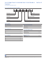
EntelliGuard™ G Cassettes Nomenclature
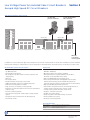
The drawout mechanism allows the breaker to be racked in four distinct positions (CONNECTED, TEST, DISCONNECTED, WITHDRAWN).
Choice of whether shutters are needed are based in the order option 2nd disconnect Block B (GSDWCR).
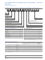
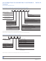
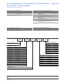
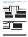
EntelliGuard™ G Cassette Product Number Structure
G
A
16
M
2
5
Digit 1
Digit 2
Digit 3,4
Digit 5
Digit 6
Digit 7
Circuit Breaker Cassette Family
G=EntelliGuard™ G
Breaker/Switch
Shutters
Shutter and Shutter LockFactory Installed
Breaker Switch Type
ANSI / UL1066 Circuit Breaker
Number of Poles
OEM Cassette - 3 Pole
Current Rating
1600 A
Cassette AIC Rating
Envelope 2, 400-3200 Envelope 3, 4000-5000
Digit 1 Circuit Breaker Cassette Family
Devices Series/Line
Digit 3 and 4 Current Rating
Code
EntelliGuard™ G Breaker/Switch
Current Rating (A)
G
Digit 2 Breaker Switch Type
Cassette Type,
Secondary Mounting
ANSI/UL1066
Circuit Breaker
UL489 Circuit Breaker
ANSI Non-auto CB
(ANSI Switch)
UL489 Non-auto CB
(UL Switch)
Side
Envelope 1
Top
Envelope 2 & 3
Top
A
N
A
B
U
B
C
M
C
D
S
D
800
1600
2000
3000
3200
5000
6000
Circuit Breaker
ANSI
UL489
08
16
20
32
50
-
08
16
20
30
60
NOTE: Select Current Rating equal to or the next higher of the Circuit Breaker or
Switch Current Rating
—Top = Top Mounted Secondary Disconnects (TSD).
—Side = Side Mounted Secondary Disconnects (SSD). (Available on Envelope 1 only).
—N, U, M, S characters are for Envelope 1 only with top mounted secondary
disconnects (TSD).
—When ordering codes A and B, Side Secondary Disconnects (SSD) are supplied as
standard on Envelope 1.
—Codes N and U, are not valid for Envelopes 2 and 3.
—Envelope 1 (Type N and H, Circuit Breaker and Switches, 800A - 2000A).
NOTE: Side Secondary Disconnects are specifically intended for 5-High
("high density") equipment designs
With Side Mounted Disconnects (SSD), EntelliGuard™ Circuit Breakers Auxiliary
Switches cannot be 8NO+8NC (Power Rated) or Aux. Switch, 4NO/4NC (Power
Rated) + 4NO/4NC (High Fidelity)
Rev. 11/13
Data subject to change
without notice
www.geindustrial.com
BuyLog™ Catalog
8-11
Low Voltage Power & Insulated Case Circuit Breakers
Section 8
™
EntelliGuard G Low Voltage Power Circuit Breakers
EntelliGuard™ G Cassettes Nomenclature
Digit 5—Cassette AIC Rating
Code
254V
S
N
H
P2
E
M
B
L
65,000
65,000
85,000
100,000
85,000
100,000
100,000
150,000
Code
240V
S
N
H
M
L
P2
65,000
65,000
85,000
100,000
150,000
100,000
Code
N
M
B
Code
N
M
B
Interrupting Rating Tier ANSI/UL1066 Devices, LVPCB
1/2S
580V
635V
Withstand
HSIOC
65,000
65,000
85,000
100,000
85,000
100,000
100,000
150,000
65,000
65,000
85,000
100,000
150,000
100,000
42,000
65,000
100,000
UL489 Non-Automatic Switches
240V
480V
42,000
65,000
150,000
50,000
65,000
65,000
65,000
85,000
85,000
100,000
100,000
50,000
None
65,000
65,000
None
85,000
None
100,000
Interrupting Rating Tier UL489 Devices ICCB
1/2S
480V
600V
Withstand
HSIOC
ANSI Non-Automatic Switches
254V
580V
42,000
65,000
100,000
50,000
65,000
65,000
65,000
85,000
100,000
100,000
100,000
42,000
65,000
150,000
50,000
65,000
65,000
100,000
100,000
65,000
42,000
42,000
50,000
65,000
85,000
50,000
42,000
42,000
50,000
65,000
85,000
50,000
Envelope 1
Override
No. 1
Override WI
Code
49,000
None
63,700
63,700
None
83,800
None
98,000
53,500
None
69,500
69,500
None
90,950
None
107,000
S
N
H
P
E
M
B
L
600V
42,000
65,000
100,000
X
X
X
Override WI
Code
400-1200
44,940
44,940
53,500
69,550
90,950
50,000
S
N
H
M
L
P
X
Note: Non-automatic switches are provided
with no internal sensing or tripping mechanism
and cannot be applied above their respective
withstand levels. If a non-automatic device is
required at ratings above the available switches
is required, it is recommended that a circuit
breaker set with maximum setting be employed
using external control or protection as required
by the application.
4000-5000
X
X
X
X
Envelope 2
400-2000 2500-3000 400-3000
X
X
Envelope 3
3000
4000-6000
X
X
X
X
X
X
X
Envelope 1
800-2000
N
M
B
Code
3200
X
X
N/A
N/A
N/A
N/A
N/A
N/A
Code
400-3200
X
X
Envelope 1
30 Cycle Withstand Ratings
3200
Envelope 3
X
Override
No. 1
635V
42,000
65,000
100,000
400-1200 400-2000
Envelope 2
Envelope 2
800-3000
Envelope 3
3000-6000
X
X
X
Envelope 1
800-2000
N
M
B
Envelope 2
800-3000
Envelope 3
3000-6000
X
X
X
Digit 6 Number of Poles
Devices Series/ Line
Code
OEM Cassette - 3 Pole
OEM Cassette - 4 Pole
GE Equipment Cassette - 3 Pole1
2
5
7
1GE
Equipment cassette designed specifically for AKD20 Switchgear.
These cassettes are NOT available for OEMs.
2P frame available as 3-pole only
Digit 7 Shutters
Shutters with Locks
Code
Shutter and Shutter Lock - Factory Installed
None
Loose Cassette Parts- Field Installed
Carriage Position Switch - 1NO/1NC
Carriage Position Switch-2NO/2NC
1 Kirk Key Interlock Cam for Cassette
1 Ronis Key Interlock Cam for Cassette
Secondary Disconnect Block B, 39 Pole-Top Mounted
Secondary Disconnect Block B, 39 Pole-Side Mounted
S
X
Product Number
GCPS1R
GCPS2R
GCKRKR
GCR0NR
GSDWTR
GSDWSR
Secondary Disconnect Block B is required when:
1. Any "ZONE SELECTIVE INTERLOCKING" options are selected in breaker/trip unit
Catalog Digit 18.
2. Any "ADVANCED FEATURES" are selected in breaker/trip unit Catalog Digit 19.
3. A COIL SIGNALING CONTACT OPTION is selected, Digit 12.
4. A READY TO CLOSE signal via the trip unit is selected, Digit 13.
5. Any of the following OPTIONAL Aux. Contact Switches are selected in Digit 12:
—8NO/NC POWER RATED
—3NO/NC POWER RATED + 2NO/NC Hi-Fi
—4NO/NC POWER RATED + 4NO/NC Hi-Fi
8-12
BuyLog™ Catalog
www.geindustrial.com
Rev. 11/13
Data subject to change
without notice
Low Voltage Power & Insulated Case Circuit Breakers
Section 8
™
EntelliGuard G Low Voltage Power Circuit Breakers
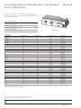
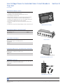
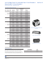
EntelliGuard™ G Accessories
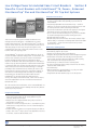
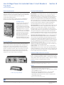
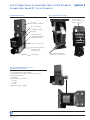
A wide range of optional accessories are interchangeable across
all EntelliGuard G power circuit breakers, regardless of nominal
rating or envelope/frame size.
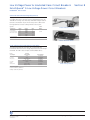
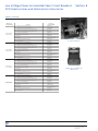
Motorized Spring Charging Unit
The unique motor/gearbox unit is specially designed to operate
with the full range of EntelliGuard G breakers. It is easily installed
with three heavy-duty bolts. After a breaker close operation, the
unit automatically recharges the spring and makes it ready for
immediate re-close should the need arise. High speed recharging
ensures that the springs are fully charged within approximately
three seconds following a release. All electrically operated (EO)
ANSI/UL breakers are equipped with “Spring Charged”
contacts for status indication.
Motorized Spring Charging Unit
Motorized Spring Charging Unit
Envelope
Power
Consumption
1
DC - 300W
1
AC - 350VA
2 and 3
DC - 480W
2 and 3
AC - 560VA
Rev. 11/13
Data subject to change
without notice
www.geindustrial.com
Nominal
Control Voltage
UL and IEC Range
(85% to 110%)
ANSI Range
Product Number
24Vdc/30Vdc
48Vdc
60Vdc
72Vdc
110Vdc/130Vdc
250Vdc
48Vac
120Vac
240Vac
277Vac
24Vdc/30Vdc
48Vdc
60Vdc
72Vdc
110Vdc/130Vdc
250Vdc
48Vac
120Vac
240Vac
277Vac
20.4V to 26.4V
40.8V to 52.87V
51V to 66V
61.2V to 79.2V
106.25V to 137.5V
212.5V to 275V
40.8V to 52.87V
102V to 132V
204V to 264V
235.5V to 304.7V
20.4V to 26.4V
40.8V to 52.87V
51V to 66V
61.2V to 79.2V
106.25V to 137.5V
212.5V to 275V
40.8V to 52.87V
102V to 132V
204V to 264V
235.5V to 304.7V
38V to 56V
100V to 140V
200V to 280V
104V to 127V
208V to 254V
38V to 56V
100V to 140V
200V to 280V
104V to 127V
208V to 254V
-
GM01024DR
GM01048DR
GM01060DR
GM01072DR
GM01110DR
GM01250DR
GM01048AR
GM01120AR
GM01240AR
GM01277AR
GM02024DR
GM02048DR
GM02060DR
GM02060DR
GM02110DR
GM02250DR
GM02048AR
GM02120AR
GM02240AR
GM02277AR
BuyLog™ Catalog
8-13
Low Voltage Power & Insulated Case Circuit Breakers
Section 8
™
EntelliGuard G Low Voltage Power Circuit Breakers
EntelliGuard™ G Accessories
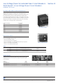
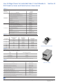
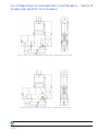
Circuit Breaker Closing Coils - Standard and Command
Two, easy-to-fit, clip-on closing coil options with simple,
plug-in connections are available. Both options offer
electrical remote release of the spring charged closing
mechanism. Both options include a standard anti-pump
safety feature ensuring that the close signal must be
released before further close commands are allowed. The
Command Close Coil additionally provides for local breaker
close and remote breaker close over communications via
the EntelliGuard Trip Unit.
Command Operation Module
This module energizes the closing coil to cause the breaker
to close whenever control power is applied to the accessory
and when commanded from the breaker trip unit or breaker
front panel push button (electrical closing.)
Close Coil
Closing Coil / Command Operation Module
Power
Consumption
DC: 350W,
20 W (sealed)
Type
Closing Coil (CC)
Nominal
Control Voltage
24Vdc
48Vac/dc
60 to 72Vdc
110/130/120Vac
208Vac
220Vdc/240Vac
250Vdc/277Vac
24Vdc
48Vac/dc
60 to 72Vdc
110/130/120Vac
208Vac
AC: 350W
(inrush),
20W (sealed)
DC: 350W,
20W (sealed)
Command Closing Coil (CCC)
AC: 350W (inrush),
20W (sealed)
Product Number
GCCN024DR
GCCN048R
GCCN060DR
GCCN120R
GCCN208AR
GCCN240R
GCCN277R
GCCC024DR
GCCC048R
GCCC060DR
GCCC120R
GCCC208AR
Shunt Trip for Ground Fault
Energizing the shunt trip (ST), via local or remote input, will
instantaneously activate the circuit breaker mechanism, ensuring
a rapid open operation. The shunt trip is continuously rated
and does not require an auxiliary switch in series with the coil.
The shunt trip is a straightforward, field installable accessory
available in wide range of voltages.
Norminal Control Voltage
24Vdc
48Vac/dc
70/72Vac
125Vdc
110Vdc/120Vac
208Vac
240Vac
250Vdc/277Vac
Product Number
GSTG024DR
GSTG048R
GSTG072DR
GSTG125DR
GSTG120R
GSTG208AR
GSTG240R
GSTG250DR
Shunt Trip
8-14
BuyLog™ Catalog
www.geindustrial.com
Rev. 11/13
Data subject to change
without notice
Low Voltage Power & Insulated Case Circuit Breakers
Section 8
™
EntelliGuard G Low Voltage Power Circuit Breakers
EntelliGuard™ G Accessories
Status Indication Switch (Coil Signaling Contact)
A plug-in module is available to provide status indication via the
secondary disconnects and trip unit. Coil Signaling Contacts are
available for closing coils, shunt trips and under voltage releases.
Contact is mounted on top of the Accessory Device. One of the
low signal (Hi-Fi) contacts is always wired to the trip unit.
Type and
Configuration
1 Power rated +
1 Low signal (Hi-Fi)
(1NO contact each)
Rating
AC
AC
DC
DC
AC
DC
Voltage
120Vac
250Vac
120Vac
250Vac
125Vac
30Vdc
Amps
6
6
0.5
0.25
0.1
0.1
2 Low signal (Hi-Fi)
(1NO contact each)
AC
125Vac
0.1
Product
Number
Status Indication Switch
GCSP1R
GCSP2R
Status Indication Switch
Under Voltage Release (UVR) with Fixed Time Delay
The UVR instantaneously activates the circuit breaker trip
mechanism when the source voltage drops below the low voltage
threshold. The UVR is also a simple, field installable device.
Power
Consumption
DC: 350W,
2W (sealed)
AC: 350W
(inrush),
20W (sealed)
Nominal
Control Voltage
24Vdc
30Vdc
40Vdc; 48Vac/dc
60 - 72Vdc
110Vdc/130Vdc; 120Vac
208Vac
220Vdc; 240Vac
250Vdc; 277Vac
Product Number
GUVT024DR
GUVT030DR
GUVT048R
GUVT060DR
GUVT120R
GUVT208AR
GUVT240R
GUVT277R
Under Voltage Release
Duty Cycle = 2/min.
Inrush = 350VA (AC), 350W (DC)
Holding = 60VA (AC), 50W (DC)
Rev. 11/13
Data subject to change
without notice
www.geindustrial.com
BuyLog™ Catalog
8-15
Low Voltage Power & Insulated Case Circuit Breakers
Section 8
™
EntelliGuard G Low Voltage Power Circuit Breakers
EntelliGuard™ G Accessories
Time Delay Module (TDM) for UVR (Externally Mounted)
The de-energized operation of the Undervoltage release can be
delayed. This optional, externally mounted module has an
adjustable time delay of 0 seconds to 3 seconds. The device can
be implemented to prevent undesired breaker tripping due to
momentary voltage interruptions and is connected in series with
the Undervoltage release. The time delay is in addition to the time
delay from the breaker mounted UVR accessory. The time delay
module starts counting at 50% of rated voltage.
Nominal Control Voltage
48Vdc
48Vac
60Vdc
125Vdc
120Vac
208Vac
240Vdc
240Vac
250Vdc
277Vac
Product Number
GTDM048D
GTDM048A
GTDM060D
GTDM120D
GTDM120A
GTDM208A
GTDM240D
GTDM240A
GTDM250D
GTDM277A
Time Delay Module
Ready To Close Contact
These contacts indicate that the following conditions are met and
the circuit breaker can be closed:
—The circuit breaker is open.
—The closing springs are charged.
—The circuit breaker is not locked/interlocked in open position.
—There is no standing closing signal.
—There is no standing opening signal.
Ready To Close Contact
1 NO
AC
DC
Voltage
Amps
Description
Product Number
120Vac
250Vac
125Vdc
250Vdc
6
6
0.5
0.25
High fidelity/secondary disconnect
–
Power rated/secondary disconnect
High fidelity/trip unit
GRTC2R
GRTC1R
GRTC3R
Auxiliary Switches
Auxiliary switches indicate breaker main contact position. They
change their state in the same time sequence as the breaker
main contacts.
Contact
Configuration
Power rated (3NO, 3NC)
Power rated (3NO, 3NC); low signal (Hi-Fi), (2NO, 2NC)
Power rated (8NO, 8NC)
Power rated (4NO, 4NC); low signal (Hi-Fi), (4NO, 4NC)
8-16
BuyLog™ Catalog
Power
Rated
A14 - A25
A14 - A25
A14 - A25, B4 - B13, B17 - B26
A14 - A25, B12 - B13, B25 - B26
Hi-Fi
N/A
B10 - B13, B23 - B26
N/A
B4 - B11, B17 - B24
www.geindustrial.com
Product
Number
GAUX3R
GAUX5R
GAUX6R
GAUX8R
Rev. 11/13
Data subject to change
without notice
Low Voltage Power & Insulated Case Circuit Breakers
Section 8
™
EntelliGuard G Low Voltage Power Circuit Breakers
EntelliGuard™ G Accessories
Circuit Breaker - Key Interlock Facility
This option supplies factory-installed key interlock mounting
provisions (baseplates and mechanism) on the front of the
breaker fascia. Key interlocks ensure that a circuit breaker cannot
be closed unless the dedicated key has been inserted and
secured within the lock. Circuit breakers accept ready-to-fit
interlocking device kits such as Castell, Ronis, Kirk and Profalux
for installation between related, separate circuit breakers.
Description
Baseplate and mechanism for Kirk Key
Locks (Breaker Mounted)
Baseplate and mechanism for Ronis Locks
(Breaker Mounted)
Mechanism for Ronis Key cassette interlock
(Cassette mounted)
Mechanism for Kirk Key cassette interlock
(Cassette mounted)
Product
Number
GBKRKR
Key Interlock Facility
GBRONR
GCRONR
GCKRKR
Carriage Position Switch (TOC)
Available as an option for mounting within the base of the
cassette/substructure, the carriage position switch provides six
single-pole changeover contacts (single pole, double throw) for
local or remote electrical indication of the circuit breaker status:
CONNECTED, TEST and DISCONNECTED. The DISCONNECTED
position is indicated only when minimum isolating distances
between contacts on both the main and auxiliary circuits have
been achieved. This option is in addition to the mechanical
indicators, which are fitted as standard. When installed, the
carriage switch is IP2X protected.
Switch
Configuration
Product
Number
1 NO/NC switch per position
Set of 2 NO/NC switches per position
Set of 6 NO/NC switches connected position
GCPS1R
GCPS2R
GCPS3R
Rev. 11/13
Data subject to change
without notice
www.geindustrial.com
Carriage Position Switch
(TOC)
BuyLog™ Catalog
8-17
Low Voltage Power & Insulated Case Circuit Breakers
Section 8
™
EntelliGuard G Low Voltage Power Circuit Breakers
EntelliGuard™ G Accessories
Mechanical Interlocks (Cable/Rod) (OEM Applications Only)
Available for fixed and draw-out circuit breakers, these units
enable the direct interlocking of EntelliGuard G circuit breakers,
either mounted side-by-side or stacked. The interlocking
mechanisms are connected by a specially designed cable or rod
in a 1 from 2, 1 from 3, and 2 from 3 configuration, and any mix
of current ratings/pole configurations can be accommodated.
Interlock Type
Number of
Cables Required
2 Way - Type A
2
1 from 2 - Type B
6
2 from 3 - Type C
6
1 from 3 - Type D
4
Breaker Type
Poles
Product
Number
Withdrawable
Withdrawable
Fixed
Fixed
Withdrawable
Withdrawable
Fixed
Fixed
Withdrawable
Withdrawable
Fixed
Fixed
Withdrawable
Withdrawable
Fixed
3
4
3
4
3
4
3
4
3
4
3
4
3
4
3
GI2WADR
GI3WADR
GI2FADR
GI3FADR
GI2WBR
GI3WBR
GI2FBR
GI3FBR
GI2WCR
GI3WCR
GI2FCR
GI3FCR
GI2WDTR
GI3WDTR
GI2FDTR
Refer to Section 4 of the Application Guide DET-653B for interlocking schemes.
Mechanical Interlock Cables
Standard cable lengths are shown. (Cables ordered separately.
Please contact our technical customer service department if
longer length is required.)
Product
Number
Length (M/In)
1 / 39.4
1.6 / 63
2 / 78.7
2.5 / 98.4
3 / 118/1
3.5 / 137.8
4 / 157.5
GCB1
GCB2
GCB3
GCB4
GCB5
GCB6
GCB7
Bell Alarm with Lockout
The Bell Alarm provides remote indication that the circuit breaker
has opened because of an electrical fault. The Lockout feature is
integral to the trip unit. When a Bell Alarm is supplied with the
breaker, the Trip Unit dial is set and locked to the manual position.
In order to re-close the breaker, the Lockout button must be
pushed in/reset on the Trip Unit 1-Form C contact.
Switch Configuration
Product
Number
Single pole, double throw (1-Form C contact)
GBAT1R
8-18
BuyLog™ Catalog
Bell Alarm with Lockout
www.geindustrial.com
Rev. 11/13
Data subject to change
without notice
Low Voltage Power & Insulated Case Circuit Breakers
Section 8
™
EntelliGuard G Low Voltage Power Circuit Breakers
EntelliGuard™ G Accessories
Charging Spring Status Indicator
Factory-installed on the motor, this auxiliary switch indicates
that the circuit breaker is charged and is standard with the
spring-charging motor.
Ratings
Voltage
Amps
Product Number
120Vac
250Vac
125Vdc
250Vdc
6
6
0.5
0.25
GSCC1R
Charging Spring Status
Indicator
Neutral Rogowski
The Neutral Rogoswki CT’s are used to measure the Neutral
Current and is required when Internal Ground Fault is selected on
the trip unit. There are two types available: Encased with Terminal
Screws: The Rogowski coil is encased with two terminal screws.
No additional mounting hardware is required as the encasing is
molded to the mounting dimensions.
Arrow to face
ACB connection
Fix coil to clamp
with cable ties (position
coil centrally on clamp)
Type
Envelope
58
Loose Rogowski Coil with separate mounting hardware: The coil
and mounting hardware are separate. The coil comes with the
two wire leads for connection to a terminal block.
Current
Rating (A)
Product
Number
400
600/630
800
1000
1200/1250
1600
2000
400
600/630
800
1000
1200/1250
1600
2000
2500
3000/3200
3000/3200 (1600 x 2)
4000 (2000 x 2)
5000 (2500 x 2)
6000/6400 (3200 x 2)
400
600/630
800
1000
1200/1250
1600
2000
400
600/630
800
1000
1200/1250
1600
2000
2500
3000/3200
3000/3200 (1600 x 2)
4000 (2000 x 2)
5000 (2500 x 2)
6000/6400 (3200 x 2)
G04HNRCE
G07HNRCE
G08HNRCE
G10HNRCE
G13HNRCE
G16HNRCE
G20HNRCE
G04MNRCE
G07MNRCE
G08MNRCE
G10MNRCE
G13MNRCE
G16MNRCE
G20MNRCE
G25MNRCE
G32MNRCE
G32LNRCE
G40LNRCE
G50LNRCE
G64LNRCE
G04HNRC
G07HNRC
G08HNRC
G10HNRC
G13HNRC
G16HNRC
G20HNRC
G04MNRC
G07MNRC
G08MNRC
G10MNRC
G13MNRC
G16MNRC
G20MNRC
G25MNRC
G32MNRC
G32LNRC
G40LNRC
G50LNRC
G64LNRC
110
1
Encased with
Terminal Screws
2
3
1
Loose Rogowski
Coil and
Mounting
Hardware
2
3
Rev. 11/13
Data subject to change
without notice
www.geindustrial.com
Remark: for ratings > 4000A two coils are used
Neutral Rogowski
External
BuyLog™ Catalog
8-19
Low Voltage Power & Insulated Case Circuit Breakers
Section 8
™
EntelliGuard G Low Voltage Power Circuit Breakers
EntelliGuard™ G Accessories
Door Escutcheon Kit for IP54 Protection
An optional complete IP54 front door panel is available when a
higher degree of protection is needed.
Product
Number
Description
Door Escutcheon Kit - IP54 Door Panel - Fixed/ Drawout
G54DR
Mechanical Operations Counter
IP54 Door Escutcheon
Used with either manual or motor charged circuit breakers, the
counter provides an accurate record of the cumulative number of
complete breaker closing operations.
Description
Product
Number
Mechanical Operations Counter
GMCNR
Door Interlock Kit
A door interlock mechanism may be fitted inside the cassette on
the right for Left hinged door or Left for Right hinged door. Specify
whether door is Left hand or Right hand hinged when ordering.
Door interlock is different for a cassette with side mounted
secondary disconnect.
Mechanical Operations
Counter
Product
Number
Description
Door Interlock (Left Side)
Door Interlock (Right Side)
GLHD
GRHD
Front Flat Terminations
The EntelliGuard G Fixed mounted breaker comes standard
with Back Connected Terminations. Optional Front Flat
terminations are available for front access mounting.
Door Interlock Kit
Product
Number
Description
Env1 800 - 2000A, Type N&H, Flat Front UL489,
Fixed 3 Pole Breaker Bus Bar Terminations (Top/Bottom)
Env1 800 - 2000A, Type N&H, Flat Front UL489,
Fixed 4 Pole Breaker Bus Bar Terminations (Top/Bottom)
Env2 800A - 3000A Flat Front UL489 Fixed 3 Pole
Breaker Bus Bar Terminations (Top/Bottom)
Env2 800A - 3000A Flat Front UL489 Fixed 4 Pole
Breaker Bus Bar Terminations (Top/Bottom)
Env3 4000-6000A Flat Front UL Fixed 3 Pole
Breaker Bus Bar Terminations (Top/Bottom)
Env3 4000-6000A Flat Front UL Fixed 4 Pole
Breaker Bus Bar Terminations (Top/Bottom)
GBB1TBF3
GBB1TBF4
GBB2TBF3
GBB2TBF4
GBB3TBF3
GBB3TBF4
Front Flat Terminations
8-20
BuyLog™ Catalog
www.geindustrial.com
Rev. 11/13
Data subject to change
without notice
Low Voltage Power & Insulated Case Circuit Breakers
Section 8
™
EntelliGuard G Low Voltage Power Circuit Breakers
EntelliGuard™ G Accessories
Arcing Contacts Assembly
Arcing contacts are supplied with the EntelliGuard breaker.
Product
Number
Description
Ent. Grd 1p EG1 H Type
Ent. Grd 1p EG1 S&N type
Ent. Grd 1p EG2 H&M type
Ent. Grd 1p EG2 E&N type
Ent. Grd 1p EG33200-6400A
G20HARC
G20NARC
G40MARC
G40NARC
G64LARC
Contact Wear Indicator
The contact wear indicator is a simple device that allows the user
to establish if the main contacts need replacement. It can be
used on devices of the fixed pattern (if the arc chutes can be
removed) and on devices of the draw out pattern.
Description
Product
Number
Contact Wear Indicator
GCNTW
Racking Handle
A collapsible Racking Handle is provided to rack in/out the draw
out breakers whenever needed.
Description
Product
Number
Racking Handle
GRHNR
Back Connected Terminations Fixed Envelope
Terminal assemblies are supplied with the EntelliGuard
breaker. Fixed breakers have back or front connected
terminations available.
Envelope Size
Description
Up to 1600A
1
200A
Up to 2000A
3000A UL
2
3200A ANSI
up to 4000A
3
6000A
Rev. 11/13
Data subject to change
without notice
Type
3 Pole
4 Pole
3 Pole
4 Pole
3 Pole
4 Pole
3 Pole
4 Pole
3 Pole (Top Side)
3 Pole (Bottom Side)
4 Pole (Top Side)
4 Pole (Bottom Side
3 Pole
4 Pole
3 Pole (Top Side)
3 Pole (Bottom Side)
4 Pole (Top Side)
4 Pole (Bottom Side)
www.geindustrial.com
Product
Number
GBB116TBB3
GBB116TBB4
GBB120TBB3
GBB120TBB4
GBB220TBB3
GBB220TBB4
GBB230TBB3
GBB230TBB4
GBB232TBB3
GBB232BBB3
GBB232TBB4
GBB232BBB3
GBB340TBB3
GBB340TBB4
GBB360TBB3
GBB360BBB3
GBB360TBB4
GBB360BBB4
BuyLog™ Catalog
8-21
Low Voltage Power & Insulated Case Circuit Breakers
Section 8
™
EntelliGuard G Low Voltage Power Circuit Breakers
EntelliGuard™ G Accessories
Back Connected Terminations For Cassette
Envelope Size
Description
Up to 1600A
1
200A
Up to 1600A
Up to 2000A
2
3000A UL
3200A ANSI
3
6000A
Type
3 Pole
4 Pole
3 Pole
4 Pole
3 Pole
4 Pole
3 Pole
4 Pole
3 Pole
4 Pole
3 Pole (Top Side)
3 Pole (Bottom Side
4 Pole (Top Side)
4 Pole (Bottom Side
3 Pole (Top Side)
3 Pole (Bottom Side)
4 Pole (Top Side)
4 Pole (Bottom Side)
Product
Number
GBB216TBBC3
GBB216TBBC4
GBB220TBBC3
GBB220TBBC4
GBB216TBBC3
GBB216TBBC4
GBB220TBBC3
GBB220TBBC4
GBB230TBBC3
GBB230TBBC4
GBB232TBC3
GBB232BBC3
GBB232TBC4
GBB232BBC4
GBB360TBC3
GBB360BBC3
GBB360TBC4
GBB360BBC4
Envelope 1 and 2, 3 Pole
1600A
Cluster Pad
Product
Number
Envelope Size
Description
1
Cluster Pad (set per phase) Qty 2 per
Cluster Pad (single cluster) 2000A Qty 2 per
Cluster Pad (double cluster) 2500A - 3200A Qty 2 per
Cluster Pad Qty 2 per
2
3
GBB120TBD
GBB220TBD
GBB232TBD
GBB360TBD
Envelope 2, Cluster Pad
(Single Cluster) 2000A
Cluster
Envelope Size
Description
Product
Number
1
36 finger (95x20 mm) Qty 1
36 finger (95x20 mm) Qty 1
36 finger (95x15 mm) Qty 1
36 finger (95x15 mm) Qty 1
G20NCLS
G20MCLS
G32ECLS
G64LCLS
2
3
Fixed Secondary Disconnect (Breaker Mounted)
Fixed breakers are always supplied with a secondary disconnect
(auxiliary connection block) suitable for 39 connection points
(terminal A). When the number of factory installed accessories
exceeds the available number of connection points needed,
a 2nd connection block is automatically added (terminal B).
For cases where the accessories are mounted in the field, an
additional auxiliary connection block can be added to provide
39 more connections.
Product
Number
Description
Fixed Breaker Top Mounted Secondary Disconnect,
39 Pole Male/Female
Fixed Breaker Top Mounted Secondary Disconnect,
78 Pole Male/Female
Fixed Breaker Side Mounted Secondary Disconnect,
78 Pole Male/Female
8-22
BuyLog™ Catalog
GSDFTR1
GSDFTR2
GSDFSR
www.geindustrial.com
Rev. 11/13
Data subject to change
without notice
Low Voltage Power & Insulated Case Circuit Breakers
Section 8
™
EntelliGuard G Low Voltage Power Circuit Breakers
EntelliGuard™ G Accessories
Network Interlock Device (NI)
The Network Interlock Device locks the breaker in the OFF
position electrically and mechanically. When this device receives
a pulse all local breaker functionality is disabled, except the tripping of the device on any over current fault. On the receipt of a
2nd pulse normal operation is re-instated. The presence of mains
power does not affect the locking and/or re-instatement of this
device. Each device has a local RESET button that only can be
accessed after breaker cover removal.
Product
Number
Description
Network Interlock 120V, UL Listed
GNTK120R
Remote Racker
The Remote Racking Operator allows the user to move a draw
out circuit breaker between the CONNECT and DISCONNECT positions via an electric racking gear head motor and the cassette
housing the breaker. The remote racking operator requires
115Vac, 60Hz control power. A control box connected
to the operator with a thirty-foot cord permits control from a
remote location.
Description
Product
Number
Remote Racker
EGGRRLV
Lifting Devices
Poles
Frame
3
3
4
4
ACB Lifting Truck
1 and 2
3
1 and 2
3
Product
Number
GLD3F12
GLD3F3
GLD4F12
GLD4F3
ACBLIFT
For more accessories and options, see the EntelliGuard™ G Application Guide
DET-653B.
Frame 3,
3 Pole
Rev. 11/13
Data subject to change
without notice
Frame 1 & 2,
4 Pole
www.geindustrial.com
Frame 1 & 2,
3 Pole
Frame 3,
4 Pole
BuyLog™ Catalog
8-23
Low Voltage Power & Insulated Case Circuit Breakers
Section 8
™
WavePro Circuit Breakers with EntelliGuard TU, Power+, Enhanced
MicroVersaTrip ™ Plus and MicroVersaTrip ™ PM Trip Unit Systems
Instantaneous Protection
There are four trip unit systems available for WavePro Low
Voltage Power Circuit Breakers — EntelliGuard™ TU, Power+,
Enhanced MicroVersaTrip™ Plus and MicroVersaTrip™ PM. All four
systems consist of the trip unit, the trip actuator, current sensors
and rating plugs. The term “trip unit systems” applies to the
combination of these four components, which form the circuit
breaker solid-state tripping system.
The EntelliGuard™ TU Trip Unit is the latest addition to the list of
trip units available on GE low voltage power circuit breakers. The
new functions offered by the trip unit enhance the WavePro
breaker with Waveform Recognition Instantaneous which
improves coordination with current limiting devices and reduces
nuisance trips by discerning whether a downstream breaker/fuse
is clearing the fault. The unit also provides optimum circuit safety
and arc flash protection with the Reduced Energy Let Through,
providing a faster instantaneous trip that may be used in case
faster and more sensitive protection is temporarily required. Its
Zone Selective Interlocking provides the ability to overlap the
Instantaneous on the Main and Feeder breakers and the
EntelliGuard™ TU also has Flexible Time Current Curves:
44 Long Time Shapes (I2T and I4T (fuse)), 3 Short Time I2T slopes,
Short Time adjustable in 55 msec increments and a Selective
Ground Fault curve.
—Instantaneous pick up is adjustable up to 15 times plug rating
on every circuit breaker and, optionally, up to 30 times on
some breakers.
—A separately adjustable fast instantaneous trip — useful for
when the circuit must provide the best possible protection and
arc flash performance while sustaining normal load
—An override instantaneous provides fast tripping for the largest
bolted fault currents to minimize potential damage.
—Up to 17 Short Time bands allow you to set your circuit breaker
to sustain load requirements without slowing protection.
—Ground Fault Alarm via I/O, or
—Ground fault protection with faster time bands, multiple slopes
and the ability to coordinate a 1200A ground fault with an 800A
circuit breaker — a ratio four times better than in previous
generation trip units
Maintenance and Diagnostics
—Universal spare trip unit that will fit any GE circuit breaker
—Universal trip plug fits any trip unit
—Flexible serial communication via Modbus RTU
—Integrates directly into GE’s EnerVista™ Power Management System
—Health status via breaker LED indicating normal operation,
errors, pickup, and trips while providing non-volatile memory
with a continuous self-testing microprocessor
—Lithium battery to eliminate need for external power
—10 event Log with Date/Time Stamp: Stores the last 10 events.
Date/Time with 24VDC Power.
—Thermal Memory
—WaveForm Capture: 40 Samples/Cycle, 4 cycles prior and 4
cycles post event in COMTrade format
—Large backlit LCD with detailed, easy to see descriptions
All of the new functions and features in the new EntelliGuard™ TU
trip unit provide ultimate system reliability and selectivity without
sacrificing circuit protection.
Designed for Flexibility
—A wide range of continuous adjustment Long Time delays
ensure the circuit breaker can be exactly dialed in to your
selectivity and protection needs.
—Multiple Short Time diagonal bands tune your protection to
exactly where it needs to be.
—Flexible time current settings and curves — Standard Long Time
characteristics exactly mimic the curve of a thermal magnetic
circuit breaker.
—Flexible Time Current Curves: 44 Long Time Shapes (I2T and I4T
(fuse)), 3 Short Time I2T slopes, Short Time adjustable in 55 msec
increments, a Selective Ground Fault curve
8-24
BuyLog™ Catalog
www.geindustrial.com
Rev. 11/13
Data subject to change
without notice
Low Voltage Power & Insulated Case Circuit Breakers
Section 8
™
WavePro Circuit Breakers with EntelliGuard TU, Power+, Enhanced
MicroVersaTrip ™ Plus and MicroVersaTrip ™ PM Trip Unit Systems
The Power+ trip unit continues to use GE’s proven technique of
measuring true rms currents of both sinusoidal and harmonically
distorted waveforms. The frequent sampling (48 times per cycle
per phase) allows precise calculations of true rms current. The
sampling rate allows waveform measurements up to the 11th
harmonic. True rms sensing avoids potential under- or over-protection problems associated with peak-sensing tripping systems.
Standard Functions:
—Rating plug with test port
Protection
—Long-time, Instantaneous (Instantaneous may be omitted
when short-time is provided)
Optional Functions:
Protection
—Short-time protection, with selectable l2t
The Power+ trip unit is identified by its plug-in modules and rotary
—Ground fault protection, with selectable l2t
switches. The optional “target module” provides LED targets for
—Defeatable ground fault (not UL)
overload, short circuit and ground fault trips. View and Reset push
buttons are also provided to monitor status, including a battery
Target Module
check LED. Standard 3-volt lithium batteries in the target module —View and Reset buttons
power the indicating LEDs (batteries are not required for trip unit
—Battery check LED
operation). The “rating plug module” serves the dual purpose of
—Longtime pickup/trip unit “health” LED
establishing the trip rating for the circuit breaker as well as
—LEDs for overload, short circuit, ground fault trips
providing ground fault protection when required. All pickup and
delay settings are selected with detented rotary switches.
Enhanced MicroVersaTrip™ Plus
and MicroVersaTrip™ PM trip
units also measure true rms
currents (and voltages for
MicroVersaTrip™ PM trip units).
The higher sampling rate (64
times per cycle) allows waveform measurements up to
the 31st harmonic to achieve
accuracy of 99%.
MicroVersaTrip™ Plus and
MicroVersaTrip™ PM trip units
contain a digital liquid crystal
display with a five-button keypad for local setup and readout of trip
settings. The trip units have a lithium battery for cold setup capability
and viewing of targets without external power. The LCD and keypad
also provide a three-phase ammeter and trip indicators.
Standard Functions:
—Rating plug with test port
Protection
—Long-time, Instantaneous (Instantaneous may be omitted
when short-time is provided)
Status
—Trip target (trip type)
—Trip information (magnitude and phase)
—Trip operations counters
Metering Display
—Phase current (selectable among phases)
Optional Functions:
—Short-time protection, with selectable l2t
—Ground fault protection, with selectable l2t
—Defeatable ground fault (not UL)
—Switchable instantaneous/short-time and ground fault (not UL).
—Zone-selective interlock, for ground fault only or for both ground
fault and short-time protection.
The Enhanced MicroVersaTrip™ (MVT) PM trip unit adds power
management system capability, including advanced metering and
Additional Functions available only with MicroVersaTrip™ PM trip unit:
protective relaying, to the basic functions of the MVT Plus. The
MVT PM can be interfaced with either Modbus RTU or Ethernet
—Communication and metering (M-option)
TCP/IP compatible systems.
—Communication, metering and protective relaying (PM-option)
All trip units utilize a series of interchangeable rating plugs to
Communication:
establish the current rating of the breaker.
—Remote communication with POWER LEADER™
Power Management Control System (PMCS) software
Metering:
—Voltage (V), Energy (kWh/MWh/GWh)
—Real Power (kW/MW), Total Power (kVA/MVA)
—Demand Power (kW/MW), Peak demand power (kW/MW)
—Frequency (Hz)
Protective Relaying:
—Undervoltage, Overvoltage
—Voltage unbalance, Current unbalance, Power reversal
Rev. 11/13
Data subject to change
without notice
www.geindustrial.com
BuyLog™ Catalog
8-25
Low Voltage Power & Insulated Case Circuit Breakers
Section 8
WavePro Low Voltage Power Circuit Breakers
How to select WavePro low voltage power
circuit breakers — One step at a time
This selection guide allows you to systematically arrive at the product
number for a WavePro OEM breaker. It also contains information you
can use to specify applicable fuses, neutral current transformers and
other associated devices (Tables A-1 to A-4 on pages 8-30 and 8-31
and Tables B-5 to B-12 on pages 8-44 and 8-45) and to select and
order substructures and substructure accessories (Tables B-1 to B-4
on pages 8-40 to 8-44). The WavePro Breaker Application Guide (DET167) contains additional information that will help you select options
to specify for your particular application.
submitting your order. Here’s an example of the selection based on
a WavePro breaker with the following specifications: digits with X
indicate no option or accessory. Example is on pages 8-26 through
8-28. Breaker selection starts on page 8-33. An alternative to
developing the breaker product number and pricing manually is to
generate the same information electronically via the web wizards at
www.geindustrial.com/industrialsystems/wizards/peb_oem_am/home.htm
Short Circuit Ratings RMS Symmetrical
Rated
AC
Voltage
Nominal
(Max.)
First, determine the appropriate WavePro breaker type from Table
A-1 on page 8-30.
Using that information, follow the step-by-step instructions beginning on page 8-33 to select options and accessories. At the end
of each step, transfer the resulting product number digit(s) for
your selection to the appropriate boxes in the Product Number
Line. Helpful Hint: Make a photocopy of the Product Number Line
(page 8-29) every time you follow this process so you can use the
form again.
480
(508)
When you’re done, you’ll have a complete breaker product number.
Note: To order, you must submit a complete 15-digit breaker
product number. If you reach a point where no further options or
accessories are required, fill in each of the remaining product
numbers digits with X (indicating no option or accessory) before
kA
With
Instantaneous
Trip
Without
Instantaneous
Trip
30
30
30
42
42
42
800
65
65
65
WPS-16
1600
50
50
50
WPH-16
1600
65
65
65
WPS-20
2000
65
65
65
WPS-32
3200
65
65
65
WPH-32
3200
85
85
85
WPX-32
3200
100
100
100
Breaker
Type
Frame
Size
(amps)
Short-Time
Withstand
WPS-08
800
WPH-08
800
WPX-08
WPS-40
4000
85
85
85
WPX-40
4000
100
100
100
WPS-50
5000
85
85
85
WPX-50
5000
100
100
100
Note: See WavePro configurator for pricing. Contact a sales representative for configurator.
Example
Option or Accessory
Tables A-1 to A-4
Option or Accessory
WPF-08 Breaker, 800A Frame
Step 6
240V, 50/60 Hz electric lockout
4-stage aux switch
Step 1
800A Class L Fuse, 800A Sensor
Step 7
Step 2
MVT PM Trip Unit with LSIG functions
Step 8
Bell alarm with lockout
Step 3
700A Trip Unit Rating Plug
Step 9
24V dc shunt trip (second shunt trip)
Step 4
120V ac 60Hz Electrical Charge & Close Operation
Step 10
Hidden close push button and remote charge indicator
(Note: “A” disconnect comes standard with the options selected here.)
Step 5
120V ac shunt trip, 60 Hz
Product Number Line – WavePro Breaker (Example)
WavePro
Breaker for
Substructures
W
S
Step 1
Step 2
G
C
D
Step 3
Step 4
Step 5
Step 6
Step 7
Step 8
Step 9
Step 10
E
F
1
5
A
B
B
E
Q
Future use
but "X"
required
X
GO TO STEP 2 ON PAGE 8-27
Step 1 Select Interrupting Type and Current Sensor (Example)
Current Sensor
Breaker
Type
Interrupting
Type & Rating
No Sensor1
150A
400A
800A
1A
1B
1C
1D
2D
WPS-08
Standard
—
WPH-08
High
—
2A
2B
2C
WPX-08
Extended
—
3B
3C
3D
300A Fuse
3A
—
AB
AC
AD
350A Fuse
—
BB
BC
BD
400A Fuse
—
CB
CC
CD
450A Fuse
—
DB
DC
DD
500A Fuse
—
EB
EC
ED
600A Fuse
—
FB
FC
FD
800A Fuse
—
GB
GC
GD
1000A Fuse
—
HB
HC
HD
1200A Fuse
—
JB
JC
JD
1600A Fuse
—
KB
KC
KD
Class J
Fuse
WPF-08
Class L
Fuse
8-26
BuyLog™ Catalog
www.geindustrial.com
Rev. 11/13
Data subject to change
without notice
Low Voltage Power & Insulated Case Circuit Breakers
Section 8
WavePro Low Voltage Power Circuit Breakers
Step 2 Select Trip Unit (Example)
Functions
Function
Code
Long
Time
Short
Time
Instantaneous
Defeatable
Ground
Ground
1
Fault
Fault 1
Switchable
S T or
Inst & GF 1
EntelliGuard™ Trip Unit
MicroVersaTrip™ Plus
MicroVersaTrip™ M
MicroVersaTrip™ PM
Product No. Digits
ZSI-GF
& ST
Product No. Digits
Product No. Digits
Product No. Digits
LI
GA
AJ
BJ
CJ
LIG
GB
AK
BK
CK
ZSI-G F
LIGZ1
GC
AL
BL
CL
LIGD2
GD
AM
BM
CM
LIGDZ12
GE
AN
BN
CN
LS
GF
AA
BA
CA
LS G
GH
AB
BF
CC
LSGZ1
GK
AA
BA
CA
LSGZ2
GL
AD
BD
CD
LSGD 2
GM
AE
BE
CE
LSGDZ12
GN
AF
BF
CF
LSGDZ22
GP
AG
BG
CG
LSI
GQ
AP
BP
CP
LSIG
GR
AQ
BQ
CQ
GS
AR
BR
CR
GT
AS
BS
CS
LSIGX
•
LSIGZ1
Step 3 Select Trip Unit Rating Plug By Current Sensor (Example)
Product No.
EntelliGuard™ TU
Trip Unit
MicroVersaTrip™ Plus
and Enhanced MicroVersaTrip™
PM Trip Unit
Example only - ordering information
starts on page 8-33.
Availibility by Current Sensor Rating (shaded areas indicate availibility)
Power+
X
Rating Plug
150
400
800
1600
2000
3200
4000
5000
None
1
•
•
2
•
•
•
80
3
•
•
•
100
•
•
125
4
60
5
•
•
•
150
6
•
•
•
200
7
•
•
•
225
8
•
•
•
250
9
•
•
•
300
A
•
•
•
400
B
•
•
C
•
•
•
450
500
D
•
•
•
600
E
•
•
•
700
1, 2
1
1, 2
1, 2
1, 2
1, 2
F
•
•
750
1, 2
G
•
•
•
800
1, 2
H
•
•
•
1000
J
•
•
K
•
•
1100
•
1, 2
1200
L
•
•
M
•
•
•
1500
1600
N
•
•
•
2000
P
•
•
•
2400
Q
•
•
•
2500
R
•
•
•
3000
S
•
•
•
3200
T
•
•
V
•
•
W
•
•
1, 2
1, 2
3600
•
1, 2
4000
1, 2
5000
1, 2
1At
coordinate indicated, rating plug and current sensor combination available only on MicroVersaTrip™ trip units. Not available on Power+ trip units.
2At coordinate indicated, rating plug and current sensor combination available only on EntelliGuard™ TU trip units. Not available on Power+ trip units.
Rev. 11/13
Data subject to change
without notice
www.geindustrial.com
BuyLog™ Catalog
8-27
Low Voltage Power & Insulated Case Circuit Breakers
Section 8
WavePro Low Voltage Power Circuit Breakers
Step 4 Select Charge and Close Operators (Example)
Step 9 Select Second Shunt Trip (Example)
(not available with WPS-50 5000A breakers)
Manual
Manual Charge,
Remote Close
Electrical Charge
& Close
Product
Number
Digit
Product
Number
Digit
Voltage
Product Number Digit
Voltage
Product
Number
Digit
None
X
Manual
X
—
—
120V, 60Hz
1
120V, 60 Hz
—
1
F
240V, 60Hz
3
120V, 50 Hz
—
4
H
24Vdc
B
120V, 50/60 Hz-48Vdc
—
—
N
110/125Vdc
E
240V, 60 Hz
—
3
T
240V, 50 Hz
—
6
W
48Vdc
—
A
E
110Vdc
—
B
P
125Vdc
—
C
Q
Step 10 Select Additional Options (Example)
A-Disconnect
“PM Ready”
Hidden Close
Push Button
Operation
Counter
Remote Charge
Indicator
Product No.
Digit
X (none)
A
Step 5 Select Shunt Trip (Example)
B
C
Voltage
Product Number Digit
D
None
X
E
120V, 60 Hz
1
F
208V, 60 Hz
2
G
240V, 60 Hz
3
H
70V, 60 Hz
4
J
120V, 50 Hz
5
K
208V, 50 Hz
6
L
M
Step 6 Select Undervoltage Trip OR Electric Lockout (Example)
N
P
Undervoltage
(Instantaneous)
Undervoltage
with Time Delay
Electric Lockout
Voltage
Product
Number
Digit
Product
Number
Digit
Product
Number
Digit
None
X
X
X
120V,
50/60 Hz
1
Example only - ordering information starts on page 8-33.
Note: See WavePro configurator for pricing. Contact a sales
representative for configurator.
4
208V,
50/60 Hz
3
240V,
50/60 Hz
2
24Vdc
A
G
H
48Vdc
B
110Vdc
C
125Vdc
C
5
3
J
E
J
Step 7 Select Auxiliary Switch (Example)
Auxiliary Switch
Product Number Digit
None
X
4-stage Auxiliary Switch
A
Step 8 Select Bell Alarm (Example)
8-28
Bell Alarm
Product Number Digit
None
X
Bell Alarm
A
Bell Alarm with Lockout
B
BuyLog™ Catalog
www.geindustrial.com
Rev. 11/13
Data subject to change
without notice
Low Voltage Power & Insulated Case Circuit Breakers
Section 8
WavePro Low Voltage Power Circuit Breakers
Ordering Worksheet
The step-by-step process below allows you to systematically
arrive at the product number for your WavePro OEM breaker. As a
result, you will get exactly what you need. In addition, this system
reduces the cycle time, precisely specifies your requirements,
allows tracking during production and ensures accurate invoicing.
The final product number will appear on the breaker nameplate,
so you can identify all components built into the original breaker
and compare breakers within a facility for proper application.
Follow the instructions at each step and transfer the product
number digit for each selection to the appropriate boxes in the
Product Number Line below. Note: You must submit a complete
15-digit product number when ordering. If you reach a point
where no further options or accessories are desired, fill in the
remaining product number digits with “X” (for none).
For options not listed, contact your GE Sales Engineer or
GE Switchgear Marketing for assistance.
Product Number Line—WavePro Breaker
WavePro Breaker
for Substructures
W
Step 1
Step 2
Step 3
Step 4
Step 5
Step 6
Step 7
Step 8
Step 9
Step 10
Future use, but
"X" required
X
S
Note: Photocopy this page for each breaker you select and
submit it with your order.
Date
Name
Title
Company
Address
City
State
Zip
Telephone
Fax
Note: See WavePro configurator for pricing. Contact a sales
representative for configurator.
Rev. 11/13
Data subject to change
without notice
www.geindustrial.com
BuyLog™ Catalog
8-29
Low Voltage Power & Insulated Case Circuit Breakers
Section 8
WavePro Low Voltage Power Circuit Breakers
Basic Selection Information
Table A-1.
WavePro Interrupting Ratings (50/60 Hz ac)
Rated AC Voltage,
Nominal (max)
600
(635)
480
(508)
240
(254)
Short-Circuit RMS Symmetrical kA
Breaker Type
Frame Size (amps)
Short-Time Withstand
With Instantaneous Trip
Without Instantaneous Trip
WPS-08
800
30
30
30
WPH-08
800
42
42
42
WPX-08
800
50
50
50
WPS-16
1600
42
42
42
WPH-16
1600
65
65
65
WPS-20
2000
65
65
65
WPS-32
3200
65
65
65
WPH-32
3200
85
85
85
WPX-32
3200
85
85
85
WPS-40
4000
85
85
85
WPX-40
4000
85
85
85
WPS-50
5000
85
85
85
WPX-50
5000
85
85
85
WPS-08
800
30
30
30
WPH-08
800
42
42
42
WPX-08
800
65
65
65
WPS-16
1600
50
50
50
WPH-16
1600
65
65
65
WPS-20
2000
65
65
65
WPS-32
3200
65
65
65
WPH-32
3200
85
85
85
WPX-32
3200
100
100
100
WPS-40
4000
85
85
85
WPX-40
4000
100
100
100
WPS-50
5000
85
85
85
WPX-50
5000
100
100
100
WPS-08
800
30
42
30
WPH-08
800
42
50
42
WPX-08
800
50
65
50
WPS-16
1600
50
65
50
WPH-16
1600
65
65
65
WPS-20
2000
65
65
65
WPS-32
3200
65
85
65
WPH-32
3200
85
130
85
WPX-32
3200
100
130
100
WPS-40
4000
85
130
85
WPX-40
4000
100
130
100
WPS-50
5000
85
130
85
WPX-50
5000
100
130
100
Table A-2.
Fused Breaker Ratings. Max. 600V ac 50/60 Hz.
Fuse Rating (Amps) 1
Interrupting Rating rms
Symmetrical kA
Frame Size (Amps)
Min
Max
800
300
1600
200
Breaker Type
1600
450
2500
200
WPF-16
2000
2000
2500
200
WPS-20 2
3200
2000
4000
200
WPS-32 2
4000
2000
5000
200
WPS-40 2
5000
2000
5000
200
WPS-50 2
WPF-08
1
The maximum fuse rating is the largest fuse that tests show will result in proper performance of the breaker and fuse in combination under short circuit conditions.
2
Fuses are mounted on separate fuse roll-out element and are ordered and shipped separately. See Table A-4 on page 8-31.
8-30
BuyLog™ Catalog
www.geindustrial.com
Rev. 11/13
Data subject to change
without notice
Low Voltage Power & Insulated Case Circuit Breakers
Section 8
WavePro Low Voltage Power Circuit Breakers
Basic Selection Information (continued)
Table A-3.
Allowable Fuse Sizes for WavePro WPF and WPS breakers with separate fused rollout elements.
Note: WPS breakers with separate fuse roll-out element require the open fuse lockout (OFLO) device. Select “OFLO only” option for
breakers 2000A-5000A: The “OFLO” option is standard on WPF breakers.
Ferraz-Shawmut Fuse Range (Amps) 1
Darkened areas indicate available fuse ranges
Breaker
Type
Frame
Size
WPF-08
800A
WPF-163
1600A
Class J
Sensor Rating
Rating Plug
150A
Below 150A
150A, 400A
150A
400A
225A
400A, 800A
300A
400A, 800A
400A
800A
600A
800A
700A
800A
800A
800A
400A & below
800A
500A
800A, 1600A
600A
800A, 1600A
700A
800A, 1600A
800A
1600A
1000A
1600A
1200A
1600A3
1600A3
WPS-20 2
2000A
2000A
2000A & below
WPS-32 2
3200A
3200A
3200A & below
WPS-40 2
4000A
4000A
4000A & below
WPS-50 2
5000A
5000A
5000A & below
300
350
400
450
Class L
500
600
800
1000
1200
1600
2000
2500
3000
4000
5000
1 Class L fuses less than 800A are not UL or CSA listed. Use Class J fuses for 600A and below. 800A-2000A fuses are also available as welder limiters.
2 Fuses are mounted on separate fuse roll-out element and are ordered and shipped separately. See Table B-3 on pages 8-41 to 8-42.
3 Integrally fused 1600A frame breakers (WPF-16) equipped with 2500A fuses can be furnished with rating plugs from 300-1600A. Breakers equipped with
2500A fuses cannot be modified to accept lower rated fuses. WPF-16 breakers equipped with 2000A and lower fuses cannot be upgraded to 2500A fuses.
The maximum trip rating for a WPF-16 breaker is 1200A when furnished with other than 2500A fuses (see chart for min-max fuse rating for each rating
plug value). 2500A fuses preclude the use of shutters in the breaker cubicle.
Table A-4.
Class L Fuses for Roll-out Elements on 2000A, 3200A, 4000A
and 5000A Frames
Product Numbers for Replacement Fuses
Note: These product numbers are for field-installed replacement
fuses. Original fuses for 800A and 1600A frame breakers are
integral to the breaker and are factory installed. For larger frame
breakers (2000A and greater), customers must provide and separately mount fuses.
Class J & Class L Breaker Mounted Fuses for 800A
and 1600A Frames
(replace original customer-installed fuses)
Fuse Rating
Product Number
2000A
A4BY2000-55BA
2500A
A4BY2500-55BA
3000A
A4BY3000-55BA
4000A
A4BY4000-55BA
5000A
A4BY5000-55BA
(replace original GE-installed fuses)
Fuse Rating
J
300A
A4J300
J
400A
A4J400
J
450A
A4J450
J
500A
A4J500
800A
A4J600
1600A
A4BX1600BG
2000A
A4BX2000
J
600A
Product Number
Welder Limiters for Breaker Mounted Fuses
Fuse Class
L
800A
A4BY800
L
1000A
A4BY1000BG
L
1200A
A4BY1200BG
L
1600A
A4BY1600BG
L
2000A
A4BY2000
L (Silver)
2500A
A4BQ2500GE
Rev. 11/13
Data subject to change
without notice
www.geindustrial.com
(replace original GE-installed fuses)
Fuse Rating
Product Number
A4BX800
BuyLog™ Catalog
8-31
Low Voltage Power & Insulated Case Circuit Breakers
Section 8
WavePro Low Voltage Power Circuit Breakers
EntelliGuard™ TU Trip Unit Characteristics
Envelope Size
Frame Max.
Ampere Rating
Sensor Rating
(Amperes) (S)
800
800
200, 400, 800
1600
1600
800, 1000, 1600
2000
2000
2000
2500
1000, 2000, 2500
3000
3000
4000
4000
3000
4000
Long Time
Current Setting (C) (Pick-Up)
Delay (Seconds)1
Multiple of Rating Plug Amperes (X)
Fuse Type (F-Bands) Thermal Type (C-Bands)
0.025
0.20
0.025
0.60
0.025
1.21
0.032
1.61
0.044
2.41
0.059
3.21
0.078
4.02
0.10
4.82
0.13
5.62
0.5 thru 1.0 in
0.17
6.43
Increments of 0.05
0.22
7.23
0.27
8.04
0.35
9.64
0.44
11.20
0.55
12.90
0.69
14.50
0.87
16.10
1.10
17.70
19.30
Short Time
Pick-up (Multiple
of Current Settings) (C)
Delay (Seconds)
I2T in
0.401
1.5 thru 9.0 in
Increments of 0.05
I2T out
0.10, 0.21, 0.352
Trip Unit Characteristics (continued)
Envelope Size
800
1600
2000
3000
4000
Adjutable Instantaneous
Pick-Up without ST (Multiple
of Rating Plug Amperes) (X)
Adjustable Instantaneous
Pick-Up with ST (Multiple
of Rating Plug Amperes) (X)
1.5 thru 10.0 in
0.5 increments
1.5 thru 10.0 in
0.5 increments
1.5 thru 10.0 in
0.5 increments
1.5 thru 10.0 in
0.5 increments
1.5 thru 9.0 in
0.5 increments
1.5 thru 15.0 in
0.5 increments
1.5 thru 15.0 in
0.5 increments
1.5 thru 15.0 in
0.5 increments
1.5 thru 13.0 in
0.5 increments
1.5 thru 9.0 in
0.5 increments
High Range Instantaneous
(Multiple of Frame
Short Time Rating) (H)
1.0
1.0
Pick-Up (Multiple
of Sensor Ampere Rating)
2.0 thru 0.60 in
increments of 0.01
2.0 thru 0.60 in
increments of 0.01
2.0 thru 0.60 in
increments of 0.01
2.0 thru 0.37 in
increments of 0.01
2.0 thru 0.30 in
increments of 0.01
Ground Fault
Delay with l2T
in seconds
Delay with l2T
out seconds3
0.10, 0.21, 0.35
0.10, 0.21, 0.35
.44 at 200% of
pick-up at lower
limit of band
0.10, 0.21, 0.35
0.10, 0.21, 0.35
0.10, 0.21, 0.35
1Time
delay shown at 600% of current setting at lower limit of band.
delay shown at lower limit of each band. All pick-up tolerances are ±10%.
3Time delay shown at lower limit of each band. Ground fault pick-up not to exceed 1200 amperes
2Time
8-32
BuyLog™ Catalog
www.geindustrial.com
Rev. 11/13
Data subject to change
without notice
Low Voltage Power & Insulated Case Circuit Breakers
Section 8
WavePro Low Voltage Power Circuit Breakers
Selection
Before beginning the selection process, first determine the appropriate WavePro breaker type from Table A-1 on
page 8-30. You will need this information to proceed.
Step 1 Select Interrupting Type And Current Sensor
For WPF breaker types, see Table A-3 on page 8-31 for allowable combinations of fuse size, current sensor and
rating plugs. From the table below that corresponds to your frame size, select the interrupting type and current
sensor for your breaker type. Transfer the product number digits to the box marked Step 1 in the Product
Number Line on the Ordering Worksheet (page 8-29). Note: Power fuses and open fuse lockout (OFLO) devices
are included for WPF type 800 and 1600 amp fused breakers.
800 Amp Frame
Current Sensor
Breaker Type
Interrupting Type & Rating
No Sensor 1
150A
400A
800A
1A
1B
1C
1D
WPS-08
Standard
—
WPH-08
High
—
2A
2B
2C
2D
WPX-08
Extended
—
3A
3B
3C
3D
Class J Fuse
WPF-08
Class L Fuse
Welder Limiter
300A Fuse
AB
AC
AD
350A Fuse
BB
BC
BD
400A Fuse
CB
CC
CD
450A Fuse
DB
DC
DD
500A Fuse
EB
EC
ED
600A Fuse
FB
FC
FD
800A Fuse
GB
GC
GD
HD
1000A Fuse
HB
HC
1200A Fuse
JB
JC
JD
1600A Fuse
KB
KC
KD
800A Fuse
—
ND
1600A Fuse
—
QD
1 Draw-out breaker only, non-automatic.
1600 Amp Frame
Current Sensor
No Sensor 1
800A
WPS-16
Standard
—
1E
1F
1G
WPH-16
High
—
2E
2F
2G
450A Fuse
DF
—
500A Fuse
EF
—
600A Fuse
FF
FG
Breaker Type
Interrupting Type & Rating
Class J Fuse
Class L Fuse
WPF-16
Welder Limiter
1600A
800A Fuse
GF
GG
1000A Fuse
HF
HG
1200A Fuse
JF
JG
1600A Fuse
KF
KG
2000A Fuse
LF
LG
2500A Fuse
MF
MG
800A Fuse
NF
NG
1600A Fuse
QF
QG
2000A Fuse
RF
RG
1 Draw-out breaker only, non-automatic.
Rev. 11/13
Data subject to change
without notice
www.geindustrial.com
BuyLog™ Catalog
8-33
Low Voltage Power & Insulated Case Circuit Breakers
Section 8
WavePro Low Voltage Power Circuit Breakers
Selection (continued)
Step 1 (continued)
2000 Amp Frame
Breaker
Type
WPS-20
3200 Amp Frame
Interrupting
Type
No
Sensor 1
Standard
1H
Breaker
Type
2000A
Sensor
1J
OFLO only 2
WPS-32
4J
4000 Amp Frame
Breaker
Type
WPS-40
No
Sensor 1
Standard
1K
3200A
Sensor
1L
OFLO only 2
4L
WPH-32
High
2K
2L
WPX-32
Extended
3K
3L
5000 Amp Frame
Interrupting
Type
No
Sensor 1
Standard
1M
4000A
Sensor
Breaker
Type
WPS-50
4N
Extended
Interrupting
Type
1N
OFLO only 2
WPX-40
Interrupting
Type
3M
3N
WPX-50
5000A
Sensor
Standard
1R
OFLO only 2
4R
Extended
3R
1 Draw-out breaker only, non-automatic.
2 Includes OPEN FUSE LOCKOUT (OFLO) device. Use with separate
fuse roll-out element (see TABLE B-2 on page 8-40).
Step 2 Select Trip Unit
From the table below, select your trip unit. Transfer the product number digits to the boxes marked Step 2 in the Product Number Line to the box
marked Step 2 in the Price Column.
EntelliGuard™ TU Trip Unit Functions
The new EntelliGuard™ TU Trip Unit includes new functions like the Reduced Let Through Energy Instantaneous (RELT) as well as
Instantaneous Zone Selective Interlocking (I-ZSI).
WavePro Catalog Number - Code 5
ZSI-GF,
ST3
ZSI-GF,
ST & INST.
RELT
Modbus
Communication
Monitoring
Data
Acquisition
Relaying
•
•
•
•
•
•
•
•
•
•
•
•
•
•
•
•
•
•
•
•
•
3Requires
8-34
•
•
•
•
•
•
•
•
•
•
•
•
•
•
•
•
•
•
•
•
•
•
•
•
•
•
•
•
•
•
•
•
•
•
•
•
•
•
•
•
•
•
Ammeter
Product No.
Digit
•
•
•
•
•
•
•
•
•
•
•
•
•
•
•
•
•
•
X (none -automatic)
N
P
Q
R
S
T
V
W
1
2
3
4
Z
5
6
7
8
9
zone selective interlock module, Type TIM1 (120Vac control voltage).
BuyLog™ Catalog
www.geindustrial.com
Rev. 11/13
Data subject to change
without notice
Low Voltage Power & Insulated Case Circuit Breakers
Section 8
WavePro Low Voltage Power Circuit Breakers
Selection (continued)
Step 2 (Cont.)
WavePro Catalog Number - Code 6
Function
Code
Long
Time
Short
Time
LSI
LSIG
LSIGA
LSIGDA2
LSI2
LSIG2
LSIGA2
LSIGDA3
•
•
•
•
•
•
•
•
•
•
•
•
•
•
•
•
2Switchboard
Instantaneous
Non-Switchable
Instantaneous
Ground
Fault1
Product No.
Digit
•
•
•
•
•
•
•
•
•
•
•
P
Q
1
2
U
7
8
9
•
•
•
•
Applications
MicroVersaTrip™ Trip Unit
All MicroVersaTrip™ trip units include integral targets and ammeter display. MicroVersaTrip™ M adds full metering and communications; MicroVersaTrip™ PM adds relaying, metering and communications.
MicroVersaTrip™ Plus
Functions
Function
Code
Long
Time
Short
Time
Instantaneous
Ground
Fault 1
Defeatable
Ground
Fault 1,3
Switchable
ST or Inst
& GF 1,3
ZSI-GF 4
ZSI-GF
& ST 4
Product
No. Digits
MicroVersaTrip™ PM
Product
No. Digits
Product
No. Digits
LI
AJ
BJ
CJ
LIG
AK
BK
CK
LIGZ1
AL
BL
CL
LIGD3
AM
BM
CM
LIGDZ13
AN
BN
CN
LS
AA
BA
CA
LSG
AB
BB
CB
LSGZ1
AC
BC
CC
LSGZ2
AD
BD
CD
LSGD 3
AE
BE
CE
LSGDZ13
AF
BF
CF
LSGDZ23
AG
BG
CG
LSI
AP
BP
CP
LSIG
AQ
BQ
CQ
LSIGX 3
AR
BR
CR
LSIGZ1
AS
BS
CS
LSIGZ2
AT
BT
CT
LSIGD 3
AV
BV
CV
LSIGDZ13
AW
BW
CW
LSIGDZ23
AY
BY
CY
•
1 Ground fault is 3-wire/4-wire. If 4-wire ground fault is required, then one of the A-Disconnect options in Step 10 must be selected and the sensor for
the 4th wire (neutral) must be ordered separately. See Table B-5 on page 8-44.
3 Function combination is not UL Listed.
4 Requires zone selective interlock module, Type TIM1 (120Vac control voltage).
Rev. 11/13
Data subject to change
without notice
www.geindustrial.com
BuyLog™ Catalog
8-35
Low Voltage Power & Insulated Case Circuit Breakers
Section 8
WavePro Low Voltage Power Circuit Breakers
Selection (continued)
Step 3 Select Trip Unit Rating Plug By Current Sensor
Select your rating plug and current sensor combination. Transfer the product number digit to the box marked Step 3 in the product
number line.
Product No.Digits
EntelliGuard™ TU
Trip Unit
MicroVersaTrip™ Plus
and Enhanced MicroVersaTrip™
PM Trip Unit
Availability by Current Sensor Rating (shaded areas indicate availability)
Power +
X
150
Rating Plug
400
800
1600
2000
3200
4000
5000
None
1
•
•
2
•
•
3
•
4
60
•
80
•
•
100
•
•
125
5
•
•
•
150
6
•
•
•
200
7
•
•
•
225
8
•
•
•
250
9
•
•
•
300
A
•
•
•
400
B
•
•
C
•
•
•
500
D
•
•
•
600
E
•
•
•
700
1, 2
1
1, 2
1, 2
450
1, 2
1, 2
F
•
•
750
1, 2
G
•
•
•
800
1, 2
H
•
•
•
1000
•
1200
•
1600
J
•
•
K
•
•
L
•
•
M
•
•
1100
1500
N
•
•
•
2000
P
•
•
•
2400
Q
•
•
•
2500
R
•
•
•
3000
•
S
•
•
T
•
•
V
•
•
W
•
•
1, 2
1, 2
3200
1, 2
3600
•
1, 2
4000
1, 2
5000
1, 2
1At
coordinate indicated, rating plug and current sensor combination available only on MicroVersaTrip™ trip units. Not available on Power+ trip units.
2At coordinate indicated, rating plug and current sensor combination available only on EntelliGuard™ TU trip units. Not available on Power+ trip units.
Step 4 Select Charge and Close Operators
Select your charge and close options. Transfer the product number digits to the box marked Step 4 in the Product Number Line.
Manual
Manual Charge, Remote Close1
Electrical Charge & Close 1
Charge-Close Voltage
Product No.
Digit
Product No.
Digit
Product No.
Digit
Manually Operated
X
—
120V, 60 Hz
1
F
120V, 50 Hz
4
H
120V, 50/60 Hz - 48Vdc
—
N
240V, 60 Hz
3
T
240V, 50 Hz
6
W
E
48Vdc
A
110Vdc
B
P
125Vdc
C
Q
D
R
250Vdc
1 Requires the selection of a shunt trip in Step 5 and a 4-stage or higher auxiliary switch in Step 7.
8-36
BuyLog™ Catalog
www.geindustrial.com
Rev. 11/13
Data subject to change
without notice
Low Voltage Power & Insulated Case Circuit Breakers
Section 8
WavePro Low Voltage Power Circuit Breakers
Step 5 Select Shunt Trip
Select your shunt trip. Transfer the product number digit to the box marked Step 5 in the
Product Number Line. (Note: All shunt trips require the selection of a 4- or 7-stage auxiliary switch in Step 7. Second shunt trip may be selected in Step 9.)
Voltage
Product
Number Digit
Voltage
Product
Number Digit
240V/50 Hz
7
None
X
120V, 60 Hz
1
208V, 60 Hz
2
24Vdc
B
240V, 60 Hz
3
48Vdc
D
70V, 60 Hz
4
110/125Vdc
E
120V, 50 Hz
5
250Vdc
F
208V, 50 Hz
6
Shunt Trip
Step 6 Select Undervoltage Trip OR Electric Lockout
Select your undervoltage trip or electric lockout option. Transfer the product number
digit to the box marked Step 6 in the Product Number Line.
Undervoltage (Instantaneous)
Undervoltage with
Time Delay 1
Electric Lockout
Product
Number Digit
Product
Number Digit
Product
Number Digit
X
X
Voltage
None
120V, 50/60 Hz
4
1
32
208V, 50/60 Hz
33
240V, 50/60 Hz
2
24Vdc
A
G
5
48Vdc
B
H
110Vdc
C
J
125Vdc
C
E4
J
250Vdc
D
F5
K
Undervoltage Trip/Electric Lockout
1 Time delay module is provided as a separate component.
2 Order static time delay TAKYUVT5 separately. See Table B-6 on page 8-44.
3 Order static time delay TAKYUVT4 separately. See Table B-6 on page 8-44.
4 Order static time delay TAKYUVT1 separately. See Table B-6 on page 8-44.
5 Order static time delay TAKYUVT2 separately. See Table B-6 on page 8-44.
Step 7 Select Auxiliary Switch
Select your auxiliary switch option. Transfer the product number digit to the box marked
Step 7 in the Product Number Line.
Auxiliary Switch
Product No. Digit
None
X
4-stage Auxiliary Switch
A
7-stage Auxiliary Switch
B
Step 8 Select Bell Alarm/Push Button Cover
Select your bell alarm option. Transfer the product number digit to the box marked Step 8
in the Product Number Line.
Bell Alarm
Push Button Cover
Product No. Digit
None
None
X
Bell Alarm
None
A
Bell Alarm with Lockout
None
B
None
CLOSE PB Cover
C
D
Bell Alarm
CLOSE PB Cover
Bell Alarm with Lockout
CLOSE PB Cover
E
None
OPEN PB Cover
F
Bell Alarm
OPEN PB Cover
G
Bell Alarm with Lockout
OPEN PB Cover
H
None
CLOSE & OPEN PB Cover
J
Bell Alarm
CLOSE & OPEN PB Cover
K
Bell Alarm with Lockout
CLOSE & OPEN PB Cover
L
Rev. 11/13
Data subject to change
without notice
www.geindustrial.com
Auxiliary Switch
Bell Alarm
BuyLog™ Catalog
8-37
Low Voltage Power & Insulated Case Circuit Breakers
Section 8
WavePro Low Voltage Power Circuit Breakers
Step 9 Select Second Shunt Trip
If you selected a shunt trip in Step 5 and require another, select
your second shunt trip option. Transfer the product number digit
to the box marked Step 9 in the Product Number Line.
Note: Second shunt trip requires the selection of a 7-stage auxiliary switch in Step 7.
Voltage
Product No. Digit
None
X
120V, 60 Hz
1
240V, 60 Hz
3
24Vdc
B
110/125Vdc
E
250Vdc
F
Step 10 Select Additional Options
Select your combination of additional options. Transfer the product number digit to
the box marked Step 10 in the Product Number Line.
A-Disconnect 1
“PM Ready”
Hidden Close
Push Button 2
Operation
Counter
Remote Charge
Indicator
Product No. Digit
X (none)
A
B
C
D
E
F
G
H
J
K
L
Optional Hidden Close
button feature shown
1 The 36-point A-Disconnect is automatically supplied if any of the following options were selected in
previous steps:
—zone selective interlock
—shunt trip
—auxiliary switch
—bell alarm
—undervoltage trip
—electrical lockout device
—electric charge and close
—MicroVersaTrip PM trip unit (”M” or “PM” option)
Select the A-Disconnect here only if (1) none of these options were selected in previous steps and
4-wire ground fault is required or (2) none of these options were selected in previous steps and your
WavePro breaker is to be “PM ready.” “PM ready” wiring includes inputs for 24V dc auxiliary power,
communications, and 3 phase voltage.
2 Available only on breakers with electrical charge and close option.
8-38
BuyLog™ Catalog
www.geindustrial.com
Rev. 11/13
Data subject to change
without notice
Low Voltage Power & Insulated Case Circuit Breakers
Section 8
WavePro Low Voltage Power Circuit Breakers
WavePro Breaker Power+ and MicroVersaTrip™ Plus/PM Rating Plugs
Breaker Frame
Size (Amps)
Current Sensor
(Amps)
150
800
4000
800
800
1600
1600
2000
3200
4000
5000
Rev. 11/13
Data subject to change
without notice
2000
3200
4000
5000
Power+
Rating Plug
with Defeatable GF
MicroVersaTrip™
Plus/PM
Rating Plug
N/A
N/A
TR1B60
TR1C80GF
TR1C80GFD
TR1B80
TR1C100GF
TR1C100GFD
TR1B100
TR1C125
TR1C125GF
TR1C125GFD
TR1B125
TR1C150
TR1C150GF
TR1C150GFD
TR1B150
GTP0150U0104
N/A
N/A
N/A
TR4B150
200
GTP0200U0204
TR4C200
TR4C200GF
TR4C200GFD
TR4B200
225
GTP0225U0306
TR4C225
TR4C225GF
TR4C225GFD
TR4B225
250
GTP0250U0407
TR4C250
TR4C250GF
TR4C250GFD
TR4B250
300
GTP0300U0408
TR4C300
TR4C300GF
TR4C300GFD
TR4B300
400
GTP0400U0410
TR4C400
TR4C400GF
TR4C400GFD
TR4B400
300
GTP0300U0408
N/A
N/A
N/A
TR8B300
400
GTP0400U0410
TR8C400
TR8C400GF
TR8C400GFD
TR8B400
450
GTP0450U0612
N/A
N/A
N/A
TR8B450
500
GTP0500U0613
TR8C500
TR8C500GF
TR8C500GFD
TR8B500
600
GTP0600U0616
TR8C600
TR8C600GF
TR8C600GFD
TR8B600
700
GTP0700U0816
TR8C700
TR8C700GF
TR8C700GFD
TR8B700
800
GTP0800U0820
TR8C800
TR8C800GF
TR8C800GFD
TR8B800
600
GTP0600U0616
N/A
N/A
N/A
TR16B600
800
GTP0800U0820
TR16C800
TR16C800GF
TR16C800GFD
TR16B800
1000
GTP1000U1025
TR16C1000
TR16C1000GF
TR16C1000GFD
TR16B1000
1100
GTP1100U1225
N/A
N/A
N/A
TR16B1100
1200
GTP1200U1232
TR16C1200
TR16C1200GF
TR16C1200GFD
TR16B1200
1600
GTP1600U1640
TR16C1600
TR16C1600GF
TR16C1600GFD
TR16B1600
750
GTP0750U0820
N/A
N/A
N/A
TR20B750
800
GTP0800U0820
N/A
N/A
N/A
TR20B800
1000
GTP1000U1025
TR20C1000
TR20C1000GF
TR20C1000GFD
TR20B1000
1200
GTP1200U1232
TR20C1200
TR20C1200GF
TR20C1200GFD
TR20B1200
1500
GTP1500U1640
N/A
N/A
N/A
TR20B1500
1600
GTP1600U1640
TR20C1600
TR20C1600GF
TR20C1600GFD
TR20B1600
2000
GTP2000U2050
TR20C2000
TR20C2000GF
TR20C2000GFD
TR20B2000
1200
GTP1200U1232
TR32C1200
TR32C1200GF
TR32C1200GFD
TR32B1200
1600
GTP1600U1640
TR32C1600
TR32C1600GF
TR32C1600GFD
TR32B1600
2400
GTP2400U2564
TR32C2400
TR32C2400GF
TR32C2400GFD
TR32B2400
3200
GTP3200U3264
TR32C3200
TR32C3200GF
TR32C3200GFD
TR32B3200
1600
GTP1600U1640
TR40C1600
TR40C1600GF
TR40C1600GFD
TR40B1600
2000
GTP2000U2050
TR40C2000
TR40C2000GF
TR40C2000GFD
TR40B2000
2500
GTP2500U2564
TR40C2500
TR40C2500GF
TR40C2500GFD
TR40B2500
3000
GTP3000U3064
TR40C3000
TR40C3000GF
TR40C3000GFD
TR40B3000
3600
GTP3600U4064
N/A
N/A
N/A
TR40B3600
4000
GTP4000U4064
TR40C4000
TR40C4000GF
TR40C4000GFD
TR40B4000
3200
GTP3200U3264
N/A
N/A
N/A
TR50B3200
4000
GTP4000U4064
N/A
N/A
N/A
TR50B4000
5000
GTP5000U5064
N/A
N/A
N/A
TR50B5000
Power+
Rating Plug
w/o GF
Rating Plug
(Amps)
EntelliGuard™ TU
60
GTP0060U0101
N/A
80
GTP0080U0101
TR1C80
100
GTP0100U0103
TR1C100
125
GTP0125U0103
150
GTP0150U0104
150
www.geindustrial.com
Power+
Rating Plug
with GF
BuyLog™ Catalog
8-39
Low Voltage Power & Insulated Case Circuit Breakers
Section 8
OEM Substructures and Substructure Accessories
Table B-1.
Breaker Substructures
NOTE: Use shallow substructures unless there are other deep substructures
in the line-up.
Frame Size
Breaker Type
Shallow (29")
WPS-08
WPH-08
800
WPX-08
WPF-08
WPS-16
1600
WPH-16
WPF-16
WPS-20
2000
WPS-20 with OFLO
3200
4000
5000
Substructure Type
Substructure Product No.
WPS08SUBSH1
Deep (36")
WPS08SUBDP1
Shallow (29")
WPH08SUBSH1
Deep (36")
WPH08SUBDP1
Shallow (29")
WPX08SUBSH1
Deep (36")
WPX08SUBDP1
Deep (36")
WPF08SUBDP1
Shallow (29")
WPS16SUBSH1
Deep (36")
WPS16SUBDP1
Shallow (29")
WPH16SUBSH1
Deep (36")
WPH16SUBDP1
Deep (36")
WPF16SUBDP1
Deep, with 2500A
CL Fuses (36")
WPF16SUBDP2
Shallow (29")
WPS20SUBSH1
Deep (36")
WPS20SUBDP1
Shallow (29")
WPS20SUBSH2
Deep (36")
WPS20SUBDP2
WPS-32
Shallow (29")
WPS32SUBSH1
WPS-32 with OFLO
Shallow (29")
WPS32SUBSH2
WPH-32
Shallow (29")
WPH32SUBSH1
WPX-32
Shallow (29")
WPX32SUBSH1
WPS-40
Shallow (29")
WPS40SUBSH1
WPS-40 with OFLO
Shallow (29")
WPS40SUBSH2
WPX-40
Shallow (29")
WPX40SUBSH1
WPS-50
Deep (36")
WPS50SUBDP1
WPS-50 with OFLO
Deep (36")
WPS50SUBDP2
WPX-50
Deep (36")
WPX50SUBDP1
Large frame sub-structure
(shown with optional accessories)
Table B-2.
Fuse Rollout Elements and Substructures for Drawout Equipment Substructures
600 Volts AC, 50/60 Hz
NOTE: When used in conjunction with these fuse roll out elements, WavePro Type WPS
drawout circuit breaker elements should be equipped with an open fuse lockout (OFLO)
device, and the WPS breaker substructure should be ordered with a Keylock Mounting
Kit. Key interlock is supplied and mounted by the customer.
Fuse Roll Out Element (FRE)
Only (No Fuses) 1,2
FRE Drawout Substructures 2,3
Frame Size
Substructure
Type
Product No.
Product No.
2000A/3200A
Shallow
WP32FRE
WP32FRSUBSH1
4000A
Shallow
WP40FRE
WP40FRSUBSH1
5000A
Deep
WP50FRE
WP50FRSUBSH1
1 Fuse rollouts accept special Class L fuses 2000-5000 Amps. See WavePro Application Guide
(DET-167) for additional information.
2 UL recognized component.
3 Substructures for fuse rollouts include provision for keylock mounting as standard feature.
8-40
BuyLog™ Catalog
www.geindustrial.com
Rev. 11/13
Data subject to change
without notice
Low Voltage Power & Insulated Case Circuit Breakers
Section 8
OEM Substructures and Substructure Accessories
Table B-3
Breaker Substructures Accessories
Substructure accessories shown assembled are shipped separately for field installation.
Substructure
Product Number
WPS08SUBSH1
WPH08SUBSH1
WPX08SUBSH1
WPS08SUBDP1
WPH08SUBDP1
WPX08SUBDP1
WPF08SUBDP1
Accessory
Accessory
Product Number
Secondary Disconnect (bracket only)
WPSDSFSH1
Secondary Disconnect (one 36-pin block)
WPSDSUBM1
CT Hardware Mounting Kit, Metering Type (for 3 CTs)
WPCTMTG1
CT Hardware Mounting Kit, Relaying Type (for 3 CTs)
WPCTMTG2
One-stage Position Switch Kit
WPPSMTG1
Three-stage Position Switch Kit
WPPSMTG2
Shutter Kit
WPSHMTG1
Padlock Kit
Standard on breaker
Keylock Mounting Kit (bracket only)
WPSKLMTG1
Door Interlock Kit
WPDIMTG1
Secondary Disconnect (bracket only)
WPSDSFDP1
Secondary Disconnect (one 36-pin block)
WPSDSUBM1
CT Hardware Mounting Kit, Metering Type (for 3 CTs)
WPCTMTG1
CT Hardware Mounting Kit, Relaying Type (for 3CTs)
WPCTMTG2
One-stage Position Switch Kit
WPPSMTG3
Three-stage Position Switch Kit
WPPSMTG4
Shutter Kit
WPSHMTG2
Padlock Kit
Standard on breaker
Keylock Mounting Kit (bracket only)
WPSKLMTG1
Door Interlock Kit
WPDIMTG1
Secondary Disconnect (bracket only)
WPSDSFDP1
Secondary Disconnect (one 36-pin block)
WPSDSUBM1
CT Hardware Mounting Kit, Metering Type (for 3 CTs)
WPCTMTG1
CT Hardware Mounting Kit, Relaying Type (for 3 CTs)
WPCTMTG2
One-stage Position Switch Kit
WPPSMTG5
Three-stage Position Switch Kit
WPPSMTG6
Shutter Kit
WPSHMTG3
Padlock Kit
Standard on breaker
Keylock Mounting Kit (bracket only)
WPSKLMTG1
Door Interlock Kit
WPDIMTG1
Secondary disconnect blocks
Secondary disconnect bracket
with disconnects installed
CT mounting hardware kit
Rev. 11/13
Data subject to change
without notice
www.geindustrial.com
BuyLog™ Catalog
8-41
Low Voltage Power & Insulated Case Circuit Breakers
Section 8
OEM Substructures and Substructure Accessories
Table B-3 (continued)
Breaker Substructures Accessories (cont.)
Substructure
Product Number
WPS16SUBSH1
WPH16SUBSH1
WPS16SUBDP1
WPH16SUBDP1
WPF16SUBDP1
(Fuse <2500A)
WPF16SUBDP2
(Fuse = 2500A)
8-42
Accessory
Accessory
Product Number
Secondary Disconnect (bracket only)
WPSDSFSH1
Secondary Disconnect (one 36-pin block)
WPSDSUBM1
CT Hardware Mounting Kit, Metering Type (for 3 CTs)
WPCTMTG1
CT Hardware Mounting Kit, Relaying Type (for 3 CTs)
WPCTMTG2
One-stage Position Switch Kit
WPPSMTG1
Three-stage Position Switch Kit
WPPSMTG2
Shutter Kit
WPSHMTG1
Padlock Kit
Standard on breaker
Keylock Mounting Kit (bracket only)
WPSKLMTG1
Door Interlock Kit
WPDIMTG1
Secondary Disconnect (bracket only)
WPSDSFDP1
Secondary Disconnect (one 36-pin block)
WPSDSUBM1
CT Hardware Mounting Kit, Metering Type (for 3 CTs)
WPCTMTG1
CT Hardware Mounting Kit, Relaying Type (for 3 CTs)
WPCTMTG2
One-stage Position Switch Kit
WPPSMTG3
Three-stage Position Switch Kit
WPPSMTG4
Shutter Kit
WPSHMTG2
Padlock Kit
Standard on breaker
Keylock Mounting Kit (bracket only)
WPSKLMTG1
Door Interlock Kit
WPDIMTG1
Secondary Disconnect (bracket only)
WPSDSFDP1
Secondary Disconnect (one 36-pin block)
WPSDSUBM1
CT Hardware Mounting Kit, Metering Type (for 3 CTs)
WPCTMTG1
CT Hardware Mounting Kit, Relaying Type (for 3 CTs)
WPCTMTG2
One-stage Position Switch Kit
WPPSMTG5
Three-stage Position Switch Kit
WPPSMTG6
Shutter Kit
WPSHMTG3
Padlock Kit
Standard on breaker
Keylock Mounting Kit (bracket only)
WPSKLMTG1
Door Interlock Kit
WPDIMTG1
Secondary Disconnect (bracket only)
WPSDSFDP1
Secondary Disconnect (one 36-pin block)
WPSDSUBM1
CT Hardware Mounting Kit, Metering Type (for 3 CTs)
WPCTMTG1
CT Hardware Mounting Kit, Relaying Type (for 3 CTs)
WPCTMTG2
One-stage Position Switch Kit
WPPSMTG7
Three-stage Position Switch Kit
WPPSMTG8
Shutter Kit
Contact factory
Padlock Kit
Standard on breaker
Keylock Mounting Kit (bracket only)
WPSKLMTG1
Door Interlock Kit
WPDIMTG1
BuyLog™ Catalog
www.geindustrial.com
Position switch kit
Shutter kit as installed on
substructure
Rev. 11/13
Data subject to change
without notice
Low Voltage Power & Insulated Case Circuit Breakers
Section 8
OEM Substructures and Substructure Accessories
Table B-3. (continued)
Breaker Substructures Accessories (cont.)
Substructure
Product Number
WPS20SUBSH1
WPS20SUBSH2
WPS20SUBDP1
WPS20SUBDP2
WPS32SUBSH1
WPS32SUBSH2
WPH32SUBSH1
WPX32SUBSH1
WPS40SUBSH1
WPS40SUBSH2
WPX40SUBSH1
WPS50SUBDP1
WPS50SUBDP2
WPX50SUBDP1
Accessory
Accessory
Product Number
Secondary Disconnect (bracket only)
WPSDSFSH1
Secondary Disconnect (one 36-pin block)
WPSDSUBM1
CT Hardware Mounting Kit, Metering Type (for 3 CTs)
WPCTMTG1
CT Hardware Mounting Kit, Relaying Type (for 3 CTs)
WPCTMTG2
One-stage Position Switch Kit
WPPSMTG1
Three-stage Position Switch Kit
WPPSMTG2
Shutter Kit
WPSHMTG1
Padlock Kit
Standard on breaker
Keylock Mounting Kit (bracket only)
WPSKLMTG1
Door Interlock Kit
WPDIMTG1
Secondary Disconnect (bracket only)
WPSDSFDP1
Secondary Disconnect (one 36-pin block)
WPSDSUBM1
CT Hardware Mounting Kit, Metering Type (for 3 CTs)
WPCTM1G1
CT Hardware Mounting Kit, Relaying Type (for 3 CTs)
WPCTMTG2
One-stage Position Switch Kit
WPPSMTG3
Three-stage Position Switch Kit
WPPSMTG4
Shutter Kit
WPSHMTG2
Padlock Kit
Standard on breaker
Keylock Mounting Kit (bracket only)
WPSKLMTG1
Door Interlock Kit
WPDIMTG1
Secondary Disconnect (bracket only)
WPSDLFSH1
Secondary Disconnect (one 36-pin block)
WPSDSUBM2
CT Hardware Mounting Kit, Metering Type (for 3 CTs)
WPCTMTG1
CT Hardware Mounting Kit, Relaying Type (for 3 CTs)
WPCTMTG2
One-stage Position Switch Kit
WPPSMTG9
Three-stage Position Switch Kit
WPPSMTG10
Shutter Kit
WPSHMTG4
Padlock Kit
WPPKMTG1
Keylock Mounting Kit (bracket only)
WPSKLMTG2
Door Interlock Kit
WPDIMTG2
Secondary Disconnect (bracket only)
WPSDLFDP1
Secondary Disconnect (one 36-pin block)
WPSDSUBM2
CT Hardware Mounting Kit, Metering Type (for 3 CTs)
WPCTMTG3
CT Hardware Mounting Kit, Relaying Type (for 3 CTs)
Contact factory
One-stage Position Switch Kit
WPPSMTG9
Three-stage Position Switch Kit
WPPSMTG10
Shutter Kit
WPSHMTG5
Padlock Kit
WPPKMTG2
Keylock Mounting Kit (bracket only)
WPSKLMTG3
Door Interlock Kit
WPDIMTG3
Padlock kit (standard on small
frame breakers, optional on
large frame breakers)
Keylock mounting kit bracket
Door interlock kit
Continued on next page
Rev. 11/13
Data subject to change
without notice
www.geindustrial.com
BuyLog™ Catalog
8-43
Low Voltage Power & Insulated Case Circuit Breakers
Section 8
OEM Substructures and Substructure Accessories
Table B-4.
Fuse Rollout Substructure Accessories
Substructure
Product Number
WP32FRSUBSH1
WP40FRSUBSH1
WP50FRSUBSH1
Accessory
Product No.
Accessory
Secondary Disconnect (bracket only)
WPSDLFSH1
Secondary Disconnect (one 36-pin block)
WPSDSUBM2
Metering CT Hardware Mounting Kit (for three CTs)
WPCTMTG1
Relaying CT Hardware Mounting Kit (for three CTs)
WPCTMTG2
One-stage Position Switch Kit
WPPSMTG9
Three-stage Position Switch Kit
WPPSMTG10
Shutter Kit
WPSHMTG4
Padlock Kit
WPPKMTG1
Keylock Mounting Kit (bracket only)
Part of substructure
Door Interlock Kit
WPDIMTG2
Secondary Disconnect (bracket only)
WPSDLFDP1
Secondary Disconnect (one 36-pin block)
WPSDSUBM2
Metering CT Hardware Mounting Kit (for three CTs)
WPCTMTG3
Relaying CT Hardware Mounting Kit (for three CTs)
Not available
One-stage Position Switch Kit
WPPSMTG9
Three-stage Position Switch Kit
WPPSMTG10
Shutter Kit
WPSHMTG5
Padlock Kit
WPPKMTG2
Keylock Mounting Kit (bracket only)
Part of substructure
Door Interlock Kit
WPDIMTG3
Table B-5.
Neutral Current Transformers (required with 4-wire ground fault).
Circuit Breaker Sensor
Amps Rating
Neutral Sensor
Rating (Amps)
Product Number
150
100-300
TSVG303B
400, 800
300-800
TSVG508B
800
300-800
TSVG508B
1600
600-1600
TSVG516B
2000
2000
800-2000
TSVG620B
3200
3200
1200-3200
TSVG832B
4000
4000
1600-4000
TSVG940B
5000
5000
5000
TSVG950B
Frame (Amps)
800
1600
Neutral Current Transformer
Table B-6.
Static Time Delays for Undervoltage Option
1
Voltage
Static Time Delay Product No. 1
125Vdc
TAKYUVT1
250Vdc
TAKYUVT2
208 Vac (50/60 Hz)
TAKYUVT5
240 Vac (50/60 Hz)
TAKYUVT4
Must be ordered in conjunction with “Undervoltage with Time Delay” option in Step 6 on page 8-37.
Table B-7.
Miscellaneous Accessories
Accessory
Product Number
Breaker Racking Handle–Std 30" Long - Non Swivel
0324B4721G001
Breaker Racking Handle–64" Long - Non Swivel
0324B4721G002
Breaker Racking Handle–30" Long - Swivel Socket
0324B4724G001
Maintenance Closing Handle
568B386G1
Small Frame Lifting Assembly, WP08, 16, 20
0324B4551G001
Large Frame Lifting Assembly, WP32, 40
0247B8961G001
Extra Large Frame Lifting Assembly, WP50
0247B8961G003
Fuse Rollout Out Element Lifting Assembly, 3200A & 4000A
0247B8961G004
Fuse Rollout Element Lifting Assembly, 5000A
0247B8961G005
WavePro Breaker Maintenance Video (Approx. 40 minutes, VHS format) 2
DEV-042
Static Time Delay
2 Order only from Burlington OEM marketing.
8-44
BuyLog™ Catalog
www.geindustrial.com
Rev. 11/13
Data subject to change
without notice
Low Voltage Power & Insulated Case Circuit Breakers
Section 8
OEM Substructures and Substructure Accessories
Table B-8.
POWER LEADER™ Power Supply
Power supply for furnishing 24Vdc control power for EntelliGuard™ TU, MicroVersaTrip™ Plus and PM trips units.
Description
Product Number
1.5A power supply.
Maximum wire length from power supply
to trip device is 100 feet. A maximum of 45 trip
units may be powered from a single power supply.
PLPS4G01
System Requirements
(Not included with power supply)
Input power, 100VA
(85-265 Vac or 100-370 Vdc)
Table B-9.
POWER LEADER™ Voltage Conditioner
Conditions and scales 120Vac to 1.76Vac for use by the trip unit for voltage sensing. Provides transient protection. Requires isolation
PTs with 120 volt secondary. Supports up to 15 trip units at a maximum distance of 20 feet. Required for PM trip units only.
Description
Product Number
Supplies isolated bus voltage signal
to EntelliGuard™ TU and MicroVersaTrip™ PM trip units.
PLVC1G01
System Requirements
(Not included with voltage conditioners)
One set of 3 voltage conditioners required
for each sensing location. PTs also required.
Table B-10.
The hand-held Portable Battery Pack provides an independent power source for EntelliGuard™ TU, microEntelliGuard™, MicroVersaTrip™
Plus and MicroVersaTrip™ PM trip units as an alternative to a test set. The battery pack is used to power up the trip unit to set or adjust
trip set points when the breaker is on the bench or otherwise not powered up. For microEntelliGuard™ trip units, the battery pack
connects to the trip unit through the 15-pin connector. A battery pack adapter cable is required. For MicroVersaTrip™ Plus and
MicroVersaTrip™ PM trip units, the battery pack connects to the trip unit through the rating plug test jack. The battery pack requires
three standard 9 Vdc alkaline batteries (not included).
Description
Product Number
MicroVersaTrip™ Plus and PM Portable Power Pack
EntelliGuard™ TU, microEntelliGuard™ Battery Pack Adapter Cable
TVPBP
TVPBPACC
Table B-11.
MicroVersaTrip™ Rating Plug Removal Tool
Description
Product Number
MicroVersaTrip™ Rating Plug Removal Tool
TRTOOL
Table B-12.
Portable Test Set
This portable, battery powered test kit provides self-tests and functional trip/no trip tests. It also provides defeat of the ground fault
function and be used in conjunction with high current test equipment. Interface is via a plug on the front of the trip units, and tests
can be conducted with the breaker in service. Test sets use either 120Vac power source or internal batteries (not included).
Description
Trip Unit Type
Product Number
Portable Test Set
MicroVersaTrip™ only
EntelliGuard™ TU and microEntelliGuard™
TVRMS2
GTUTK20
Portable Test Set - MicroVersaTrip ™
Rev. 11/13
Data subject to change
without notice
www.geindustrial.com
Portable Test Set - EntelliGuard ™ TU and microEntelliGuard ™
BuyLog™ Catalog
8-45
Low Voltage Power & Insulated Case Circuit Breakers
Section 8
OEM Substructures and Substructure Accessories
Table B-13.
Metering and Relaying Current Transformers for 800-5000A Substructures, 600 Vac, 50/60 Hz
Breaker Frame Size
800A
1600A
2000A
3200A
4000A
5000A
8-46
Ampere Ratio ():5
Metering Product Number
Metering & Relaying Product Number
100
75C149640P001
75C149640P025
150
75C149640P002
75C149640P026
200
75C149640P003
75C149640P027
250
75C149640P004
75C149640P028
300
75C149640P005
75C149640P029
400
75C149640P006
75C149640P030
500
75C149640P007
75C149640P031
600
75C149640P008
75C149640P032
800
75C149640P010
75C149640P034
1000
75C149640P011
75C149640P035
1200
75C149640P012
75C149640P036
1500
75C149640P013
75C149640P037
1600
75C149640P014
75C149640P038
2000
75C149640P015
75C149640P039
2500
75C149640P016
75C149640P040
2000
75C149640P020
75C149640P044
2500
75C149640P021
75C149640P045
3000
75C149640P022
75C149640P046
3200
75C149640P023
75C149640P047
4000
75C149640P024
75C149640P048
5000
75C149640P049
Consult Factory
BuyLog™ Catalog
www.geindustrial.com
Rev. 11/13
Data subject to change
without notice
Low Voltage Power & Insulated Case Circuit Breakers
Section 8
OEM Substructures and Substructure Accessories
Switchgear Module and Trolley for use with Gerapid
High-Speed DC Circuit Breakers
GE offers UL recognized OEM switchgear modules and drawout
trolleys for use with Gerapid High-Speed DC circuit breakers.
Modules come factory assembled, and can be used to form
lineups of DC switchgear. The OEM provides required bussing,
wiring, controls and covers necessary to complete the switchgear.
The Trolley is designed to accept Gerapid DC breakers, interface
with the OEM Module and includes pre-wired secondary control
harness and required interlocking.
Key Module Features include:
—NEMA 1, zinc-plated bolted steel frame construction
—26” W x 87” H x 59” D
—Optional 71” depth for extra bus and cable space
—Rated for 800VDC, 200kA peak withstand
—Copper stationary primary stabs available for
2500A thru 6000A
—Side-covers and doors painted ANSI Grey
—Insulated safety shutters with padlock provisions
—Secondary control compartment with hinged, padlockable door
—21.5” H x 22.8 “ W x 8.6” D
—Breaker secondary control wiring harness and plug included
—Designed to meet ANSI C37.20.1 requirements
—UL Recognized
OEM Switchgear Modules
Key Trolley Features include:
—Designed for use with Gerapid OEM Modules
—Complete drawout trolley for Gerapid UL Listed 2508 4008,
5008 and 6008 breakers
—Breaker secondary control wiring harness & socket included
—Breaker compartment door is hinged and fixed to trolley
structure (dead front)
—Trolley front cover (door) has inspection window to view breaker
position indicator and operations counter
—Trolley is grounded in all positions
—Designed to meet ANSI C37.20.1 and C37.14 interlocking and
other requirements
—Standard manual racking drive
—Optional motor drive racking, 230VAC/60HZ
—UL Recognized
OEM Benefits
—Simplified OEM Modules (substructures)
—Complete drawout DC breaker solution
—Trolleys and Modules are UL recognized.
—Outlines available in PDF and as AutoCAD templates for OEMs
—All breaker controls prewired to secondary control disconnect
—ANSI C37.20.1 and C37.14 required interlocking included
—Accessories available, including various covers
and hardware kits
Rev. 11/13
Data subject to change
without notice
www.geindustrial.com
Gerapid
High-Speed
Circuit Breaker
Drawout Trolley
BuyLog™ Catalog
8-47
Low Voltage Power & Insulated Case Circuit Breakers
Section 8
OEM Substructures and Substructure Accessories
Substructures
Description
Gerapid OEM Module-4kA-1500mm
Gerapid OEM Module-6kA-1500mm
Gerapid OEM Module-4kA-1800mm
Gerapid OEM Module-6kA-1800mm
Product Number
700689
700690
700691
700692
Breaker Trolley
Description
Gerapid OEM Trolley-motor driven
Gerapid OEM Trolley-manual drive
Product Number
700693
700694
Accessories
Description
Racking Handle
Rear Side Cover 1500mm Depth Unit
Rear Side Cover 1800mm Depth Unit
Control Wireway Connector
Control Wireway Cover
Section Bolting Hardware Kit
Cover Attachment Harware kit
Door Hinges Kit
Product Number
700695
700696
700697
700698
700699
289158
289160
289709
To configure Gerapid OEM Modules and DC Circuit Breakers, visit our web\ wizard configuration tool at:
http://www.geindustrial.com/cwc/Dispatcher?REQUEST=PRODUCTS&id=gerapid&lang=en_US
8-48
BuyLog™ Catalog
www.geindustrial.com
Rev. 11/13
Data subject to change
without notice
Low Voltage Power & Insulated Case Circuit Breakers
Section 8
Trip Units
EntelliGuard™ TU Trip Unit Features
EntelliGuard™ TU Trip Unit
New capabilities in the EntelliGuard™ TU Trip Unit provide ultimate
system reliability and selectivity without sacrificing circuit protection. This superior addition enhances the circuit breakers with a
Waveform Recognition Instantaneous Algorithm that
eliminates costly downtime due to nuisance tripping. It enables
harmonic analysis four cycles prior and after an event, and
discerns whether a downstream breaker/fuse is clearing the fault.
The unit also includes Instantaneous Zone Selective Interlocking
(I-ZSI) (can be used as a feeder and downstream device with a
power circuit breaker upstream) which delivers simultaneous and
independent ZSI of Short Time, Ground Fault and Instantaneous
protection, providing the ability to overlap the Instantaneous on
the Main and Feeder breakers. Together, these innovative abilities
achieve HRC2 with currents as high as 100kA with simultaneous
flash protection and selectivity.
The EntelliGuard™ TU Trip Unit offers optimum circuit safety
and arc flash protection with the Reduced Energy Let-Through
function, providing a faster instantaneous trip that may be
used if faster and more sensitive protection is required
temporarily. It is commonly referred to as an “Arc Flash Switch”
or “Maintenance Switch”.
The new and improved trip unit design delivers selectivity tools
not previously available in GE circuit breakers:
Exclusive EntelliGuard™ TU Trip Unit Features
Designed for Flexibility
—A wide range of continuous adjustment Long Time delays
ensure the circuit breaker can be exactly adjusted in to your
selectivity and protection needs.
—Multiple Short Time diagonal bands tune your protection to
exactly where it needs to be.
—Flexible time current settings and curves -Standard Long Time
characteristics exactly mimic the curve of a thermal magnetic
circuit breaker.
—Flexible Time Current Curves: 44 Long Time Shapes I2T and
I4T (fuse), 3 Short Time I2T slopes, Short Time adjustable in 55
ms increments, a Selective Ground Fault curve
Instantaneous Protection
—Instantaneous pick-up is adjustable up to 15 times the plug
rating on frames 800-2000A, 13 times on 3000A frames and
up to 9 times on 4000A frames.
—A separately adjustable fast instantaneous trip- useful for
when the circuit must provide the best possible protection
and arc flash performance while sustaining normal load.
—An override instantaneous - provides fast tripping for the
largest bolted fault currents to minimize potential damage.
—Up to 17 Short Time bands allow you to set your circuit breaker to sustain load requirements without slowing protection.
—Ground Fault Alarm via I/O or Modbus Communications
—Ground fault protection with faster time bands, multiple
slopes and the ability to coordinate a 1200A ground fault
with an 800A circuit breaker – a ratio four times better than in
previous generation trip units
Rev. 11/13
Data subject to change
without notice
www.geindustrial.com
Maintenance and Diagnostics
—Universal trip plug fits any trip unit.
—Flexible serial communication via Modbus RTU
—Integrates directly into GE’s EnerVista™ Power
Management System.
—Large backlit LCD with detailed, easy-to-see descriptions.
—Health status via breaker LED indicating normal operation,
errors, pickup, and trips while providing non-volatile memory
with a continuous self-testing microprocessor
—Lithium battery to eliminate need for external power for
set-up and review
—10 event Log with Date/Time Stamp: Stores the last 10 events.
Date/Time with 24Vdc Power.
—Thermal Memory
—WaveForm Capture: 40 Samples/Cycle, 4 cycles prior and 4
cycles post event in COMTrade format.
—Free set-up software
To learn more about EntelliGuard™ TU Trip Unit
features see brochure DEA-461C.
BuyLog™ Catalog
8-49
Low Voltage Power & Insulated Case Circuit Breakers
Section 8
Trip Units
Power+ Trip Unit Features
Power+ Trip Unit Systems
Trip Target Module (Optional)
The Power+ trip unit system for insulated case circuit breakers
consist of the trip unit, the trip actuator, current sensors and rating plugs. The term “trip unit system” applies to the combination
of these four components which form the solid-state
circuit breaker tripping system.
View Button: Press the VIEW button to check the trip unit status.
Power+ trip units provide a complete range of standard and
optional overcurrent and ground-fault protective functions.
True RMS Sensing
The Power+ trip unit continues to
use GE’s proven technique of
measuring true rms currents of
both sinusoidal and harmonically
distorted waveforms. The frequent
sampling (48 times per cycle per
phase) allows precise calculations
of true rms current. The sampling
rate allows waveform measurements up to the 11th harmonic.
GE’s true rms sensing avoids
potential underprotection or overprotection problems associated
with peak-sensing tripping systems.
Accessory Integration
Four accessories are integrated through the Power+ trip unit.
Drop-in shunt trip (with or without lockout), bell alarms (with or
without lockout) and the undervoltage release modules fit into
keyed pockets. They operate through the trip units, and not
through any external mechanisms. All accessory wiring is prewired to secondary terminals, and no user wiring is necessary.
When activated, the shunt trip (with or without lockout) and
undervoltage release modules send a signal to the trip unit to
energize the trip actuator and open the breaker.
Reset Button: Press the RESET button to clear any target that is set.
Battery check: Target modules use two standard, 3V, 16mm x
1.6mm, lithium batteries for viewing target information. Battery life
depends upon use, but may be estimated at one year. When the
batteries are energized, depressing the VIEW button will illuminate
either a set target LED, i.e., LT or the BAT LED. Once target indicators
are cleared, battery status is indicated by the BAT LED. Replacement
batteries include Panasonic CR1616, Eveready E-CR1616BP, or
Duracell DL1616B, which may be purchased commercially.
Long-time pickup: The long-time pickup indicator moves through
two transitions. As the current in any phase reaches 95% of its
setpoint; the LTPU LED begins to flash. As current increases,
flashing frequency increases, until 100% of the pickup point is
reached. At that moment, the LTPU LED stays on continuously until
the long-time delay times out. Once the breaker has tripped on
long-time, the OVL target will be stored in memory. To view the trip,
press the VIEW button. To clear the target, press the RESET button.
Short-time and instantaneous trips: Short-time and instantaneous
trips share the same trip target. The LTPU LED is not illuminated,
since the time intervals between pickup and tripping are too short
for either function. Once the breaker has tripped on short-time or
instantaneous, the short target will be stored in memory. To view the
trip, press the VIEW button. To clear the target, press the RESET button.
Ground fault trip (Target02 only): The trip target for a ground
fault trip is the GF LED. To view the trip, press the view button. To
clear the target, press the RESET button.
Health monitor: Trip unit health status “okay” is illustrated by
slow blinking of the LTPU LED. It may be seen by depressing and
holding the VIEW button. Sufficient power must be supplied to the
trip unit via external test kit, power pack, or current transformers
for the health monitor to be operational.
Standard and Optional Protective Functions
Standard and optional protective functions are available for
Power+ trip units. The breaker settings are programmed in multiples of “X” (rating plug ampere values), “S” (current sensor ampere
rating values), and “C” (the long-time setting in amperes—multiply
long-time setting by rating plug ampere rating).
Standard
—Adjustable Long-Time (L) Pickup, 0.5 - 1.0X, with four delay bands.
—Adjustable Instantaneous (I) Pickup, 1.5 - 15X.1
Options
Power+ Trip Target Module
—Overload, Short Circuit, and Short-Time local trip indicators with
overload pickup warning and health monitor.
—Adjustable Short-Time (S) Pickup, 1.5 - 9.0C, and delay (3 bands)
with I2t ON/OFF selection.
—Adjustable Ground Fault (G) Pickup, 0.2 - 0.6S, and delay1
(3 bands) with I2t ON/OFF selection and trip indicator.
—Upgradeable Ground Fault function with use of appropriate
ground fault rating plug.
1Limited by breaker frame size above 2000A.
8-50
BuyLog™ Catalog
www.geindustrial.com
Rev. 11/13
Data subject to change
without notice
Low Voltage Power & Insulated Case Circuit Breakers
Trip Units
Section 8
Enhanced MicroVersaTrip™ Trip Unit Features
Enhanced MicroVersaTrip™ Trip Units
TR N
I P OT
W U E
:
I
N
I
L
RE N L I M
I
T
V
M
U A EN BE S I CR
N N T O N O
PA I T U O B L V E
G S A FA R Y S O E G R S
E R C I L A A
8- E TU S E T C T
6 9 AV R D E E Y S R I P
E
A
F O I L D P L W H TA ™
R AB MV E TE EN TU
S
D L T D
E T E. T .
AI S RI
LS EE P
.
Enhanced MicroVersaTrip™ Plus and MicroVersaTrip™ PM trip units
give you two new ways to monitor and control the circuit breaker
with unprecedented ease. Through the simple keypad, the trip
unit lets you program and display a variety of functions including
tripping characteristics, remote communications, status information and protective relaying, and allows integration with GE
POWER LEADER™ Power Management Systems. The trip unit display also allows viewing of many standard metering parameters
as well as pickup alarms, trip target indications and fault
status information.
Enhanced MicroVersaTrip™ Plus and MicroVersaTrip™ PM trip
units continue to use GE’s proven technique of measuring true
rms currents (and voltages for MicroVersaTrip™ PM trip units) of
both sinusoidal and harmonically distorted waveforms. The frequent sampling (64 times per cycle) allows precise calculations of
true rms current. The sampling rate allows waveform measurements up to the 31st harmonic to achieve accuracies of 99%.
GE’s true rms sensing avoids potential underprotection or overprotection problems associated with peak-sensing tripping systems.
Enhanced MicroVersaTrip ™ Plus and MicroVersaTrip ™ PM Trip
Units have been specifically designed to integrate with the
extensive capabilities offered by circuit breakers.
The enhanced trip unit design includes a wide range of functions
and adds many new features:
UL Listed Field-Interchangeable
Features exclusive to MicroVersaTrip™ PM Trip Units
Non-volatile trip targets display/Cold setup capability
—Replaceable long-life batteries provide trip target indications
and cold setup capability—without the need for external
power or a battery pack.
Communications
—All information can be viewed on the LCD display or
communicated over a POWER LEADER™ Power
Management System network.
Trip operations counter
—The number of long-time, short-time, instantaneous and
ground fault trips are individually counted and displayed.
Demand/peak demand
—The trip unit can display a rolling average of power demand
and peak power demand at user-selected intervals from 5 to
60 minutes.
Trip information
—On overcurrent faults, the trip unit displays fault pickup, the
type of fault, the magnitude of the fault current and the
phase the fault occurred on.
—Display indicates when a shunt trip or undervoltage release
trip has opened the breaker.
New display
—Ergonomic, 5-button keypad
—New targets with international symbols
—High-resolution LCD display for local 3-phase ammetering
—New status and setup displays for greater ease of use
—True rms sensing for accurate response to high harmonic
content waveforms for Long-Time, Short-Time, and Ground
Fault protection.
—50/60 Hz operation.
—Interchangeable, UL Listed trip units and rating plugs with test
set jack for TVRMS2 test set.
—EMI immunity per ANSI C37.90.
Rev. 11/13
Data subject to change
without notice
www.geindustrial.com
Local and remote metering
—Amps, volts, frequency
—Real power, total power
—Accumulated energy
Protective relays include:
—Current and voltage unbalance
—Overvoltage
—Undervoltage
—Power reversal
—Power reversal direction setup
BuyLog™ Catalog
8-51
Low Voltage Power & Insulated Case Circuit Breakers
Trip Units
Section 8
Trip Unit Characteristics
EntelliGuard™ TU Trip Unit Characteristics
Envelope Size
Frame Max.
Ampere Rating
Sensor Rating
(Amperes) (S)
800
800
200, 400, 800
1600
1600
800, 1000, 1600
2000
2000
2000
2500
1000, 2000, 2500
3000
4000
3000
3000
4000
4000
Long Time
Current Setting (C) (Pick-Up)
Delay (Seconds)1
Multiple of Rating Plug Amperes (X)
Fuse Type (F-Bands) Thermal Type (C-Bands)
0.025
0.20
0.025
0.60
0.025
1.21
0.032
1.61
0.044
2.41
0.059
3.21
0.078
4.02
0.10
4.82
0.13
5.62
0.5 thru 1.0 in
0.17
6.43
Increments of 0.05
0.22
7.23
0.27
8.04
0.35
9.64
0.44
11.20
0.55
12.90
0.69
14.50
0.87
16.10
1.10
17.70
19.30
Short Time
Pick-up (Multiple
of Current Settings) (C)
Delay (Seconds)
I2T in
Minimum - 0.046
Intermediate - 0.186
Maximum - 0.4181
1.5 thru 9.0 in
Increments of 0.5
I2T out
0.025, 0.033, 0.042,
0.058, 0.092, 0.117,
0.158, 0.183, 0.217,
0.350, 0.4172
Trip Unit Characteristics (continued)
Envelope Size
Adjustable Instantaneous
Pick-Up without ST (Multiple
of Rating Plug Amperes) (X)
Adjustable Instantaneous
Pick-Up with ST (Multiple
of Rating Plug Amperes) (X)
RELT
without ST
RELT
with ST
Pick-Up (Multiple of
Sensor Ampere Rating)
2.0 thru 10.0 in
0.5 increments
2.0 thru 10.0 in
0.5 increments
2.0 thru 10.0 in
0.5 increments
2.0 thru 10.0 in
0.5 increments
2.0 thru 9.0 in
0.5 increments
2.0 thru 15.0 in
0.5 increments
2.0 thru 15.0 in
0.5 increments
2.0 thru 15.0 in
0.5 increments
2.0 thru 13.0 in
0.5 increments
2.0 thru 9.0 in
0.5 increments
1.5 thru 10.0 in
0.5 increments
1.5 thru 10.0 in
0.5 increments
1.5 thru 10.0 in
0.5 increments
1.5 thru 10.0 in
0.5 increments
1.5 thru 9.0 in
0.5 increments
1.5 thru 15.0 in
0.5 increments
1.5 thru 15.0 in
0.5 increments
1.5 thru 15.0 in
0.5 increments
1.5 thru 13.0 in
0.5 increments
1.5 thru 9.0 in
0.5 increments
0.20 thru 0.60 in
increments of 0.01
0.20 thru 0.60 in
increments of 0.01
0.20 thru 0.60 in
increments of 0.01
0.20 thru 0.37 in
increments of 0.01
0.20 thru 0.30 in
increments of 0.01
800
1600
2000
3000
4000
Delay with I2T
in Seconds
.44 at 200%
of pick-up
at lower
limit of
band
Ground Fault3
Slope
Bands
Fixed
Delay
0.058
0.092
0.117
0.158
0.183
0.217
0.35
0.417
0.517
0.617
0.717
0.817
0.917
I2T
- .385
I2T - .385
I4T
- .179
I4T - .179
SGF - .553
SGF - .553
1Time
delay shown at 600% of current setting at lower limit of band.
delay shown at lower limit of each band. All pick-up tolerances are ±10%.
3Time delay shown at lower limit of each band. Ground fault pick-up not to exceed 1200 amperes
2Time
Additional Features and Characteristics of the EntelliGuard™ TU Trip Unit
Product Number Digit
Function
Metering
Communications
Amperes (A, kA)2
Voltage (V)
Energy (kWh, Mwh, GWh)
Real Power (kW/MW)
Total Power (kVA/MVA)
Frequency (Hz)
Demand & Peak Demand (kW)
Relaying
Description
Under Voltage Trip
Adjustable pickup, 50-90%
Adjustable delay, 1-15 seconds OFF
Adjustable pickup, 110-150%
Adjustable delay, 1-15 seconds OFF
Adjustable pickup, 10-50%
Adjustable delay, 1-15 seconds OFF
Adjustable pickup, 10-990kW
Adjustable delay, 1-15 seconds Off
Power Reversal Direction
Modbus Communications Bus Link
Selectable Phase Current ±2.5%
L-L or L-N Volts ±1.5%
Total Energy Usage on Brkr ±4%
L-L or L-N Power ±4%
L-L or L-N Power ±4%
Circuit Frequency ±1Hz
Over Voltage Trip
Voltage Unbalance
Current Unbalance
Data Acquisition - Waveform Capture
RELT
4Used
8-52
1
2
•
•
•
•
•
3
4
5
6
•
•
•
•
•
•
•
•
•
•
•
•
•
•
•
•
•
•
•
•
•
•
•
7
8
•
•
•
•
•
•
•
•
9
X
A4
•
•
•
B4
C4
D4
E4
•
•
•
•
•
•
•
•
•
•
•
•
•
•
•
•
•
•
•
•
•
•
•
•
•
•
•
•
•
•
•
•
•
•
•
•
•
•
•
•
•
•
•
•
•
•
•
•
•
•
•
•
when Ground Fault Alarm is needed via the output contact
BuyLog™ Catalog
www.geindustrial.com
Rev. 11/13
Data subject to change
without notice
•
Low Voltage Power & Insulated Case Circuit Breakers
Trip Units
Section 8
Trip Unit Characteristics (continued)
Additional Features and Characteristics of the EntelliGuard™ TU Trip Unit
Product No. Digits
Zone Selective Interlocking
Z
T
X
1Instantaneous out only
ZSI, Short time and GF; user selectable
Z + IOC ZSI; user selectable
NONE SELECTED
Circuit Breaker
•
•1
•
Power+ Trip Unit Characteristics
Long-Time
Envelope
Size
Frame Max.
Ampere Rating
Sensor Rating
(Amperes) (S)
800
200, 400, 800
1600
800, 1000, 1600
2000
2000
2000
3000
2500, 3000
4000
4000
Current Setting (C) (Pick-Up)
Multiple of Rating Plug Amperes (X)
Short-Time
Delay2 (Seconds 4 Bands)
Pick-up (Multiple
of Current Setting) (C)
2.4, 4.9, 9.8, 20
1.5, 2.0, 2.5, 3.0,
4.0, 5.0, 7.0, and 9.0
0.5, 0.6, 0.7,
0.8, 0.9, 0.95 and 1.0
Delay (Seconds 3 Bands)
I2T in2
.10, .21, .35
I2T out 3
.10, .21, .35
1000, 2000, 2500, 3000
4000
Power+ Trip Unit Characteristics (continued)
Ground Fault
Envelope Size
Adjustable Instantaneous Pick-Up without ST
(Multiple of Rating Plug Amperes) (X)
2000
Pick-Up (Multiple of
Sensor Ampere Rating)
Adjustable Instantaneous Pick-Up with ST
(Multiple of Rating Plug Amperes) (X)
1.5 thru 10.0
1.5 thru 15.0
0.20 thru 0.60
1.5 thru 10.0
1.5 thru 15.0
0.20 thru 0.60
1.5 thru 10.0
1.5 thru 15.0
0.20 thru 0.60
3000
1.5 thru 10.0
1.5 thru 13.0
0.20 thru 0.37
4000
1.5 thru 9.0
1.5 thru 9.0
0.20 thru 0.30
Delay4 (Seconds 3 Bands)
I 2 T in 5
.10, .21, .35
I 2 T out 3
.10, .21, .35
Enhanced MicroVersaTrip™ Plus and PM Trip Unit Characteristics
Long-Time
Envelope Size
Sensor Rating
(Amperes) (S)
Frame Max.
Ampere Rating
800
800
200, 400, 800
1600
1600
800, 1000, 1600
2000
2000
2000
2500
1000, 2000, 2500
3000
3000
4000
4000
3000
4000
Current Setting (C) (Pick-Up)
Multiple of Rating Plug Amperes (X)
Short-Time
Delay3 (Seconds)
Pick-up (Multiple of
Current Setting) (C)
Delay (Seconds)
I 2 T in2
0.40
0.5 thru 1.0 in
increments of 0.05
2.4, 4.9, 9.8, 20
1.5 thru 9.0 in
increments of 0.5
I 2 T out 3
.10, .21, .35
Trip Unit Characteristics (continued)
Envelope Size
Adjustable Instantaneous
Pick-Up without ST (Multiple
of Rating Plug Amperes) (X)
Adjustable Instantaneous
Pick-Up with ST (Multiple
of Rating Plug Amperes) (X)
High Range Instantaneous
(Multiple of Frame
Short-Time Rating) (H)
Ground Fault
Pick-Up (Multiple
of Sensor Ampere Rating)
800
1.5 thru 10.0 in
0.5 increments
1.5 thru 15.0 in
0.5 increments
0.20 thru 0.60 in
increments of 0.01
1600
1.5 thru 10.0 in
0.5 increments
1.5 thru 15.0 in
0.5 increments
0.20 thru 0.60 in
increments of 0.01
2000
1.5 thru 10.0 in
0.5 increments
1.5 thru 15.0 in
0.5 increments
3000
1.5 thru 10.0 in
0.5 increments
1.5 thru 13.0 in
0.5 increments
0.20 thru 0.37 in
increments of 0.01
4000
1.5 thru 9.0 in
0.5 increments
1.5 thru 9.0 in
0.5 increments
0.20 thru 0.30 in
increments of 0.01
1.0
2 Time delay shown at 600% of current setting at lower limit of band.
3 Time delay shown at lower limit of each band. All pick-up tolerances are ± 10%.
4 Time delay shown at lower limit of each band. Ground fault pick-up not to exceed 1200 amperes.
5 Time delay shown at 200% of pick-up at lower limit of band.
Rev. 11/13
Data subject to change
without notice
www.geindustrial.com
0.20 thru 0.60 in
increments of 0.01
Delay With l2T
In Seconds
.44 at 200% of
pick-up at lower
limit of band
Delay4 With l2T
Out Seconds
.10, .21, .35
X = Rating plug amps
S = Sensor amp rating
C = Long-time current setting (pick-up)
H = Short-Time Rating
BuyLog™ Catalog
8-53
Low Voltage Power & Insulated Case Circuit Breakers
Trip Units
Section 8
Trip Unit Characteristics (continued)
Additional Features and Characteristics Exclusive to the Enhanced MicroVersaTrip™ PM Trip Unit1
Trip Unit Suffix
Function
Communications
Description
—POWER LEADER Communications Bus Link
M (Metering)
P (Relaying)
PM (Metering & Relaying)
STD
STD
STD
STD
STD
STD
Amperes (A, kA) 2
Selectable Phase Current ±2.5%
Voltage (V)
L-L or L-N Volts ±1.5%
•
•
Energy (kWh, MWh, GWh)
Total Energy Usage on Brkr ±4%
•
•
Real Power (kW/MW)
L-L or L-N Power ±4%
•
•
Total Power (kVA/MVA)
L-L or L-N Power ±4%
•
•
Frequency (Hz)
Circuit Frequency ± 1Hz
•
•
•
•
Demand & Peak Demand (kW)
Under Voltage Trip
—Adjustable pickup 50-90%
—Adjustable delay, 1-15 seconds OFF
•
•
Over Voltage Trip
—Adjustable pickup, 110-150%
—Adjustable delay, 1-15 seconds OFF
•
•
Voltage Unbalance
—Adjustable pickup, 10-50%
—Adjustable delay, 1-15 seconds OFF
•
•
Current Unbalance
—Adjustable pickup, 10-50%
—Adjustable delay, 1-15 seconds OFF
•
•
•
•
Power Reversal
—Adjustable pickup, 10-990 kW
—Adjustable delay, 1-15 seconds OFF
—Power Reversal Direction
•
•
1 MicroVersaTrip™ PM functions require 24 Vdc control power.
2 Ampere reading also standard on MicroVersaTrip™ Plus trip units.
8-54
BuyLog™ Catalog
www.geindustrial.com
Rev. 11/13
Data subject to change
without notice
Low Voltage Power & Insulated Case Circuit Breakers
Trip Units
Section 8
Product Number Nomenclature System
EntelliGuard™ TU Trip Unit for EntelliGuard™ G Breakers Product Number Structure
G
Digit
G
1 and 2
M
3
1
6
L
4 and 5
4
6 and 7
X
6
A
R
X
X
X
X
8
9
10
11
12
13
14
15
Trip Unit
Form
EntelliGuard™
Frame Ratings
Future Use
Sensor Rating
1600
Overcurrent Ground Fault Protection
LSIG (S, switchable) (I, switchable ANSI only)
Factory or Field Install
Replacement Trip Unit
Zone Selective Interlocking
Blank
Manual / Auto Trip Reset (EntelliGuard™ G only)
Auto Reset/Reclose
Advanced Features and Communications
Monitoring + Data Acquisition, Modbus Protocol + RELT
Digit 4 and 5 Sensor Rating
Digit 1 and 2 Trip Unit Form/Family
Circuit Breaker Type
Code
Power Break™ I (UL)
Power Break™ II (UL)
AKR (ANSI)
WP (ANSI)
Mpact Low (IEC)
Mpact 24-48V (IEC)
Mpact 120-240V (IEC)
EntelliGuard™ G ACB (ANSI)
EntelliGuard™ G ACB (UL)
EntelliGuard™ G ACB (IEC)
EntelliGuard™ G Universal Spare Trip
Type A Conversion Kits (ANSI)
EntelliGuard™ G Switch (IEC)
GA
GB
GC
GW
GL
GH
GQ
GG
GU
GT
G1
G2
G3
Sensor Rating
Code
UNIV1
400
6002
800
10002
12002
1600
2000
25002
30002
32003
4000
5000
60002
1Universal
00
04
06
08
10
12
16
20
25
30
32
40
50
60
Spare Trip Unit (Digit 3 = X)
2UL
Only
3ANSI Only
Digit 3 EntelliGuard™ G Frame Ratings
Code
254V
580V
S
N
H
E
M
B
L
65,000
65,000
85,000
85,000
100,000
100,000
150,000
65,000
65,000
85,000
85,000
100,000
100,000
150,000
S
N
H
M
L
240V
480V
65,000
65,000
85,000
100,000
150,000
65,000
65,000
85,000
100,000
150,000
Interrupting Rating Tier ANSI/UL1066 Devices, LVPCB
1/2S
635V
Withstand
HSIOC
50,000
65,000
65,000
85,000
100,000
100,000
100,000
50,000
65,000
65,000
85,000
85,000
100,000
100,000
50,000
None
65,000
None
85,000
None
100,000
Interrupting Rating Tier UL489 Devices ICCB
1/2S
600V
Withstand
HSIOC
50,000
65,000
65,000
100,000
100,000
42,000
42,000
50,000
65,000
85,000
Override
No. 1
Override WI
49,000
None
63,700
None
83,800
None
98,000
53,500
None
69,500
None
90,950
None
107,000
Override
No. 1
Override WI
N/A
N/A
N/A
N/A
N/A
44,940
44,940
53,500
69,550
90,950
42,000
42,000
50,000
65,000
85,000
Refer to GEH-4567 for other Circuit Breaker Types
Rev. 11/13
Data subject to change
without notice
www.geindustrial.com
BuyLog™ Catalog
8-55
Low Voltage Power & Insulated Case Circuit Breakers
Trip Units
Section 8
Product Number Nomenclature System
Digit 6 and 7 Overcurrent Protection Package
Type
Over Current (OC) Protection Package
Code
EntelliGuard™ G ANSI/UL
OC Protection
LSI (S, switchable) (I, switchable ANSI only)
LSIG (S, switchable) (I, switchable ANSI only)
LSIGA (S, switchable) (I, switchable ANSI only) (G, Alarm Only)
LSIC (S, switchable) (I, switchable ANSI only)
LSICA (S, switchable) (I, switchable ANSI only) (C, Alarm Only)
LSIGDA1 (S, G, A switchable) (I, switchable ANSI only)
LSIGCDA1 (S, G, C, A all switchable) (I, switchable ANSI only)
LSH (S, switchable) (I, switchable ANSI only)
LSHG (S, switchable) (I, switchable ANSI only)
LSHGA (S, switchable) (I, switchable ANSI only) (G, Alarm Only)
LSHC (S, switchable) (I, switchable ANSI only)
LSHCA (S, switchable) (I, switchable ANSI only) (C, Alarm Only)
LSHGDA1 (S, G, A switchable) (I, switchable ANSI only)
LSHGCDA1 (S, G, C, A all switchable) (I, switchable ANSI only)
L3
L4
L5
L6
L7
L8
L9
LC
LD
LE
LF
LG
LH
LK
Standard Range
Instantaneous
Extended Range
Adjustable Instantaneous
1Function
Combination is NOT UL Listed
NOTES:
L = Long Time (L, I2T) + Fuse Settings (I4T) (Fuse settings are now standard on all EntelliGuard™ Trip Units)
S = Short Time (Switchable if Instantaneous (I) protection is enabled)
I = Standard Range Adjustable Instantaneous, (IOC, 2x-15x)
H = Extended Range Adjustable Instantaneous, (IOC, 2x-30x), Only for ANSI EntelliGuard™ G
G = Ground Fault Protection (GFP, 3-wire or 4-wire, internal summing) Trip and Alarm
C = External CT for ground fault detection (AKD20 application: input from external summing CTs, used for multiple source ground fault dectection.
OEM Application: Zero Sequence Input of 1A = 100%)
D = Defeatable/Switchable Ground Fault, NOT UL Listed
A = Ground Fault, External Ground Fault, Alarm only
GA = Ground Fault Alarm Only
CA = External Ground Fault Alarm Only
GDA, GCDA = Ground Fault Trip and Ground Fault Alarm (all switchable, Not UL Listed)
Digit 8 Zone Selective Interlocking (ZSI)
Zone Selective Interlocking
Digit 10 Manual/Auto Trip Reset
Code
ZSI, Short time and GF; user seletable
Z+IOC or HIOC ZSI; user selectable
Blank/none
Z
T
X
ZSI selections require Secondary Disconnect Block B and 24Vdc control power.
NOTE: Option X is the only valid item when a Switch is selected in Digit 2.
Digit 9 Advanced Features and Communications
Advanced Features and Communications
Code
Reduced Energy Let-Through (RELT)
Modbus Protocol + RELT
Profibus Protocol + RELT
Monitoring + RELT, NO Communication
Monitoring + Relay Package + RELT
Monitoring + Data Acquisition, Modbus Protocol + RELT
Monitoring + Data Acquisition, Profibus Protocol + RELT
Monitoring + Data Acquisition + Relay Package, Modbus + RELT
Monitoring + Data Acquisition + Relay Package, Profibus + RELT
NONE
1
2
3
4
5
6
7
8
9
X
Manual/Auto Trip Reset
Code
Manual Lockout
Auto Reset/Reclose
Auto/Manual Lockout (Selectable)2
None (Defaults to Auto Reset/Reclose)
M
A
S2
X
Note: When Bell Alarm with Lockout is selected on the EntelliGuard™ G Circuit
Breaker, then Code M must be selected
X is only valid on GE Legacy Circuit Breakers and Conversion Kits
M is valid on EntelliGuard™ G Breakers when a Bell Alarm is selected
A is valid on EntelliGuard™ G Breakers when a Bell Alarm is not selected
2S is IEC Only
Digit 11 Factory or Field Installed
Manual/Auto Trip Reset
Code
Factory Installed Trip Unit (Original)
Replacement Trip Unit (shipped loose)
F
R
NOTES:
All Advanced Feature selections require Secondary Disconnect Block B and
24Vdc control power
RELT = Reduced Energy Let Through
Monitoring = Advanced Metering
Data Acquisition = Waveform Capture and Harmonic Analysis
8-56
BuyLog™ Catalog
www.geindustrial.com
Rev. 11/13
Data subject to change
without notice
Low Voltage Power & Insulated Case Circuit Breakers
Trip Units
Section 8
Product Number Nomenclature System
EntelliGuard™ TU Trip Unit for Power Break™, WavePro, AK/AKR, Conversion Kit Breakers Product Number Structure
G
Digit
B
1 and 2
2
3
1
6
L
4 and 5
4
6 and 7
X
6
X
R
X
X
X
X
8
9
10
11
12
13
14
15
Trip Unit
Form
Power
Break™ II
Frame Ratings
1600 Amp Frame
Future Use
Sensor Rating
1600
Overcurrent Ground Fault Protection
LSIG (S, switchable) (I, switchable ANSI only)
Original / Replacement Trip Unit
F = Factory Installed (Original)
R = Replacement (Field Installed)
Zone Selective Interlocking
Blank
Manual / Auto Trip Reset
A, M, or S = EntelliGuard™ G only
X = for all others
Advanced Features and Communications
Monitoring + Data Acquisition, Modbus Protocol + RELT
Digit 1 and 2 Trip Unit Form/Family
Digit 4 and 5 Sensor Rating
Circuit Breaker Type
Code
Power Break™ I (UL)
Power Break™ II (UL)
AK, AKR (ANSI)
WP (ANSI)
Mpact Low (IEC)
Mpact 24-48V (IEC)
Mpact 120-240V (IEC)
EntelliGuard™ G ACB (ANSI)
EntelliGuard™ G ACB (UL)
EntelliGuard™ G ACB (IEC)
EntelliGuard™ G Universal Spare Trip
Type A Conversion Kits (ANSI)
EntelliGuard™ G Switch (IEC)
GA
GB
GC
GW
GL
GH
GQ
GG
GU
GT
G1
G2
G3
Sensor Rating
Code
150
200
225
400
600
800
1000
1200
1600
2000
2500
3000
3200
4000
5000
01
02
03
04
06
08
10
12
16
20
25
30
32
40
50
Sensor must be equal to or less than Frame Rating
Digit 3 Legacy Frame Rating by Break Type
Breaker Type
10
Code 3
Frame Rating
A
C
01
1
2
3
4
5
6
7
8
225A
600A
800A (AKR30S)
800A
1600A
2000A
2500A
3000A
3200A
4000A
5000A
Power Break™ I and II
WavePro
AKR
AK, Westinghouse,
ITE, Allis Chalmers
x
x
x
x
x
x
x
x
x
x
x
x
x
x
x
x
x
x
x
x
x
x
x
x
x
x
x
is used for only AKR30S breakers
Rev. 11/13
Data subject to change
without notice
www.geindustrial.com
BuyLog™ Catalog
8-57
Low Voltage Power & Insulated Case Circuit Breakers
Trip Units
Section 8
Product Number Nomenclature System
Digit 6 and 7 Overcurrent Protection Package
Type
Over Current (OC) Protection Package
Legacy ANSI/UL
OC Protection
LSI (S, switchable) (I, switchable ANSI only)
LSIG (S, switchable) (I, switchable ANSI only)
LSIGA (S, switchable) (I, switchable ANSI only) (G, Alarm Only)
LSIGDA1 (S, G, A switchable) (I, switchable ANSI only)
LSI (S, switchable) (I, Non-switchable UL891 applications)
LSIG (S, switchable) (I, Non-switchable UL891 applications)
LSIGA (S, switchable) (I, Non-switchable UL891 applications) (G, Alarm Only)
LSIGDA1 (S, G, A switchable) (I, Non-switchable UL891 applications)
PB1 and PBII, AK, AKR,
WavePro, Conv Kits
WavePro
1Function
Code
L3
L4
L5
L8
LP
LQ
LR
LS
Combination is NOT UL Listed
NOTES:
L = Long Time (L, I2T) + Fuse Settings (I4T) (Fuse settings are now standard on all
EntelliGuard™ Trip Units)
S = Short Time (Switchable if Instantaneous (I) protection is enabled)
I = Standard Range Adjustable Instantaneous, (IOC, 2x-15x)
G = Ground Fault Protection (GFP, 3-wire or 4-wire, internal summing), Trip and Alarm
D = Defeatable/Switchable Ground Fault, NOT UL Listed
A = Ground Fault, Alarm only
GA = Ground Fault Alarm Only
GDA = Ground Fault Trip and Ground Fault Alarm (all switchable, Not UL Listed)
Digit 8 Zone Selective Interlocking (ZSI)
Digit 11 Original/Replacement Trip Unit
Zone Selective Interlocking
Code
ZSI, Short time and Ground Fault; user selectable
ZSI, Instantaneous, Short Time, and Ground Fault; user selectable
Blank/None
All ZSI selections require a special harness (contact factory) and 24Vdc control power.
ZSI Instantaneous (T), Power Break™ can only be used as a Feeder (ZSI-I out)
Digit 9 Advanced Features and Communications
Advanced Features
and Communications
NONE (Ammeter)
Ammeter, Reduced Energy
Let-Through (RELT)
Ammeter, Modbus
Protocol + RELT
Monitoring + Data Acquisition,
Modbus Protocol + RELT
Monitoring + Data Acquisition +
Relay Package, Modbus + RELT
Ammeter, Modbus Protocol
(Without RELT)
Monitoring + Data Acquisition,
Modbus Protocol (without RELT)
Monitoring + Data Acquisition +
Relay Package, Modbus (without RELT)
Digit 9
WP
PBII
X
x
x
1
x
x
2
x
x
x
8
x
x
x
A
D
E
Circuit Break Type
Code 1 and 2
All Circuit Breakers
G
OC Protection Package
x
LSI (S, switchable) (I, switchable ANSI only)
LSIG (S, switchable) (I, switchable ANSI only)
LSIGA (S, switchable) (I, switchable ANSI only)
LSIGDA2 (S, G, A all switchable) (I, switchable ANSI only)
JSI (S, switchable) (I, switchable ANSI only)
JSIG (S, switchable) (I, switchable ANSI only)
JSIGA (S, switchable) (I, switchable ANSI only)
JSIGDA1 (S, G, A all switchable) (I, switchable ANSI only)
x
Code 6 and 7
L3
L4
L5
L8
J3
J4
J5
J8
x
x
x
x
x
x
Zone Selective Interlocking
x
None Selected
ZSI, Short time and GF; user selectable
Z + IOC or HSIOC ZSI; user selectable
x
NOTES:
All Advanced Feature selections require 24Vdc control power
RELT = Reduced Energy Let Through (Harness may be required, contact factory)
Monitoring = Advanced Metering (Harness may be required, contact factory)
Data Acquisition = Waveform Capture and Harmonic Analysis
Options A, D, E are available when Ground Fault Alarm is selected
Digit 10 Manual/Auto Trip Reset
Manual/Auto Trip Reset
Code
Manual Reset (ANSI/UL EntelliGuard™ G Only)
Automatic Reset (ANSI/UL EntelliGuard™ G Only)
Automatic Reset (IEC EntelliGuard™ G Only)
Not Applicable (Power Break™, Power Break™ II, WavePro, AKR, Conv Kits)
8-58
F
R
EntelliGuard™ TU
x
x
x
Code
Conv
Kits
AKR
6
Original/Replacement
Factory Installed (Original)
Replacement (Field Installed)
Z
T
X
BuyLog™ Catalog
Advanced Features and Communications
Code 8
X
Z
T
Code 9
None Selected
Reduced Energy Let-Through (RELT)
Modbus Protocol Only
Monitoring Only
Monitoring + Relay Package
Monitoring + Data Acquisition, Modbus Protocol
Monitoring + Data Acquisition + Relay Package, Modbus
1Function
X
1
2
4
5
6
8
Combination is NOT UL Listed
M
A
S
X
www.geindustrial.com
Rev. 11/13
Data subject to change
without notice
Low Voltage Power & Insulated Case Circuit Breakers
Section 8
Trip Units
Product Number Nomenclature System
EntelliGuard™ TU Trip Unit Rating Plug Product Numbers
GTP
1100
Trip Unit Type Rating
GTP = Trip unit rating plug
EntelliGuard™ TU Trip Unit
Rating Plug Ampere Rating
1000 = 1000A
0060 = 60A
1100 = 1100A
0080 = 80A
1200 = 1200A
0100 = 100A
1500 = 1500A
0125 = 125A
1600 = 1600A
0150 = 150A
1700 = 1700A
0200 = 200A
1800 = 1800A
0225 = 225A
1900 = 1900A
0250 = 250A
2000 = 2000A
0300 = 300A
2200 = 2200A
0350 = 350A
2400 = 2400A
0400 = 400A
2500 = 2500A
0450 = 450A
3000 = 3000A
0500 = 500A
3200 = 3200A
0600 = 600A
3600 = 3600A
0700 = 700A
4000 = 4000A
0750 = 750A
5000 = 5000A
0800 = 800A
6000 = 6000A
0900 = 900A
Trip Unit Type
U = Universal Trip Plug
Rev. 11/13
Data subject to change
without notice
www.geindustrial.com
U
12
25
Largest Current Sensor Rating
01 = 150A
16 = 1600A
02 = 200A
20 = 2000A
03 = 225A
25 = 2500A
04 = 400A
30 = 3000A
06 = 600A
32 = 3200A
07 = 630A
40 = 4000A
08 = 800A
50 = 5000A
10 = 1000A
60 = 6000A
12 = 1200A
64 = 6400A
13 = 1250A
Smallest Current Sensor Rating
01 = 150A
16 = 1600A
02 = 200A
20 = 2000A
03 = 225A
25 = 2500A
04 = 400A
30 = 3000A
06 = 600A
32 = 3200A
07 = 630A
40 = 4000A
08 = 800A
50 = 5000A
10 = 1000A
60 = 6000A
12 = 1200A
64 = 6400A
13 = 1250A
BuyLog™ Catalog
8-59
Low Voltage Power & Insulated Case Circuit Breakers
Section 8
Trip Units
Product Number Nomenclature System
Power+ Trip Unit and Power Break II Product Numbers
D2
20
LSI
T1
Trip Unit Type and Rating
D2 = Power Break™ II Power+ Trip Unit:
R1
Replacement or New
R = Replacement trip unit
(Blank) = New
2000 A sensor maximum
D3 = Power Break™ II Power+ Trip Unit:
3000 A sensor maximum
Trip unit options
T1 = Target Module without ground fault target
T2 = Target Module with ground fault target
(Blank) = Factory Installed
D4 = Power Break™ II Power+ Trip Unit:
4000 A sensor maximum
Current Sensor Rating
02 = 200 A
20 = 2000 A
04 = 400 A
25 = 2500 A
08 = 800 A
30 = 3000 A
10 = 1000 A
40 = 4000 A
16 = 1600 A
Auxiliary functions
LI = Long-time and Instantaneous
LSI = Long-time, Short-time, Instantaneous
1Device Product Number requires an extender “R” for field installable kit version only.
NOTE: This information is provided only for use interpreting product numbers. It cannot be used to build product numbers.
Power+ Rating Plug Product Numbers
TR
10
C
Trip Unit Type Rating
TR = Trip unit rating plug
All Power+, MicroVersaTrip™ Plus,
and MicroVersaTrip™ PM
rating plugs
Current Sensor Rating
02 = 200 A
20 = 2000 A
04 = 400 A
25 = 2500 A
08 = 800 A
30 = 3000 A
10 = 1000 A
40 = 4000 A
16 = 1600 A
Trip Unit Type
C = Power+ trip unit rating plugs
800
GF
Ground Fault Function
Blank = No ground fault
GF = Ground fault
Rating Plug Ampere Rating
800 = 800 A
100 = 100 A
150 = 150 A
1000 = 1000 A
200 = 200 A
1100 = 1100 A
225 = 225 A
1200 = 1200 A
250 = 250 A
1500 = 1500 A
300 = 300 A
1600 = 1600 A
400 = 400 A
2000 = 2000 A
450 = 450 A
2500 = 2500 A
500 = 500 A
3000 = 3000 A
600 = 600 A
3600 = 3600 A
700 = 700 A
4000 = 4000 A
Power+ Target Module Product Numbers
TARGET00 = Blank insert for Target Module
TARGET01 = Target Module without ground fault target
TARGET02 = Target Module with ground fault target
NOTE: This information is provided only for use interpreting product numbers. It cannot be used to build product numbers.
8-60
BuyLog™ Catalog
www.geindustrial.com
Rev. 11/13
Data subject to change
without notice
Low Voltage Power & Insulated Case Circuit Breakers
Section 8
Trip Units
Product Number Nomenclature System
Power+ Trip Unit and Power Break II Product Numbers
J
3
32
LSI
T1
R
Step 1
Step 2
Step 3
Step 4
Step 5
Step 6
Breaker Type
J = WavePro
Replacement
R = Replacement Trip Unit
Breaker Frame
3 = 3200A
Target Module Installed
TARGET01 (without ground fault)
Installed CT
32 = 3200A
Overcurrent Protection
LSI = Long Time, Short Time, Instantaneous
Power+ / WavePro
Step 4 Overcurrent Protection
Step 1 Breaker Type
Breaker Type
WavePro
Code
Overcurrent Protection
Code
J
Long-Time ( Standard)
Short-Time (Optional)
Instantaneous (Standard)
L
S
I
Step 2 Breaker Frame
Breaker Frame (max CT)
Code
800A
1600A
2000A
3200A
4000A
8
1
2
3
4
Installed CT
Code
150A
400A
800A
1600A
2000A
3200A
4000A
Data subject to change
without notice
Target Module Installed
Code
TARGET00 (Blank Insert)
TARGET01 (w/o ground fault)
TARGET02 (with ground fault)
(none)
T1
T2
Step 6 Replacement
Step 3 Installed CT
Rev. 11/13
Step 5 Target Module Installed
01
04
08
16
20
32
40
www.geindustrial.com
Replacement
Code
Replacement Trip Unit
R
BuyLog™ Catalog
8-61
Low Voltage Power & Insulated Case Circuit Breakers
Section 8
Trip Units
Product Number Nomenclature System
MicroVersaTrip™ Plus, MicroVersaTrip™ PM Trip Unit and Power Break II Product Number
B2
20
LSI
GZ1
Trip Unit Type and Rating
B2 = Power Break™ II Enhanced
MicroVersaTrip Plus™ or PM Trip Unit:
2000 A Sensor maximum
B3 = Power Break™ II Enhanced
MicroVersaTrip Plus™ or PM Trip Unit:
3000 A Sensor maximum
B4 = Power Break™ II Enhanced
MicroVersaTrip Plus™ or PM Trip Unit:
4000 A Sensor maximum
PM
R1
Remanufactured
RM = Remanufactured Trip Unit
RX = Exchanged Trip Unit
Trip Unit Options
Options for MicroVersaTrip™ PM trip units only. Must select one:
P = Protective relays & communications
M = Metering & communications
PM = Protective relays, metering, & communications
(Blank) = MicroVersaTrip™ Plus trip unit
Current Sensor Rating
02 = 200 A
20 = 2000 A
04 = 400 A
25 = 2500 A
08 = 800 A
30 = 3000 A
10 = 1000 A
40 = 4000 A
16 = 1600 A
Ground Fault Functions
G = Ground fault
GD = Ground fault defeatable (not UL listed)
GZ1 = Ground fault; zone selective interlocking for ground fault only
GZ2 = Ground fault and short-time selective interlock
GDZ2 = Ground fault defeatable (not UL listed): ground fault and
short-time selective interlock
(Blank) = None
Auxiliary Functions
LI = Long-time and instantaneous
LSI = Long-time, short-time, instantaneous
LSH = Long-time, short-time, high-range
instantaneous
1Device Product Number requires an extender “R” for field installable kit version only.
NOTE: This information is provided only for use interpreting product numbers. It cannot be used to build product numbers.
Rating Plug Product Numbers (MicroVersaTrip™ Plus and PM)
TR
10
Device Type
TR = Trip unit rating plug
All MicroVersaTrip™ Plus and
MicroVersaTrip™ PM rating plugs
Current Sensor Rating
2 = 200 A
20 = 2000 A
4 = 400 A
25 = 2500 A
8 = 800 A
30 = 3000 A
10 = 1000 A
40 = 4000 A
16 = 1600 A
B
800
Rating Plug Ampere Rating
100 = 100 A
1000 = 1000 A
150 = 150 A
1200 = 1200 A
200 = 200 A
1500 = 1500 A
225 = 225 A
1600 = 1600 A
300 = 300 A
2000 = 2000 A
400 = 400 A
2500 = 2500 A
500 = 500 A
3000 = 3000 A
600 = 600 A
3600 = 3600 A
700 = 700 A
4000 = 4000 A
800 = 800 A
Trip Unit Type
B = All Enhanced MicroVersaTrip™ Plus and MicroVersaTrip™ PM
trip unit rating plugs
NOTE: This information is provided only for use interpreting product numbers. It cannot be used to build product numbers.
8-62
BuyLog™ Catalog
www.geindustrial.com
Rev. 11/13
Data subject to change
without notice
Low Voltage Power & Insulated Case Circuit Breakers
Section 8
Trip Units
Product Number Nomenclature System
MicroVersaTrip™ Plus, MicroVersaTrip™ PM Trip Unit and WavePro Product Number
A
3
32
LSI
G
Z1
PM
R
Step 1
Step 2
Step 3
Step 4
Step 5
Step 6
Step 7
Step 8
Breaker Type
A = AKR
Remanufactured
RM = Remanufactured Trip Unit
RX = Exchanged Trip Unit
Breaker Frame
3 = 3200A
Optional Features
PM = Relaying, Metering, Communication
Installed CT
04 = 400A
Optional Protection
Z1 = Ground Fault Zone - Selective Interlock
Overcurrent Protection
LSI = Long Time, Short Time, Instantaneous
Ground Fault Protection
G = Ground Fault
MVT PLUS/PM - WavePro
Step 5 Ground Fault Protection
Step 1 Breaker Type
Breaker Type
Code
WavePro
K
Step 2 Breaker Frame
Frame Size
Code
800A
1600A
2000A
3200A
4000A
5000A
8
1
2
3
4
5
Ground Fault Protection
Code
Ground Fault
Defeatable ground fault (user defeatbale)
G
GD
Step 6 Replacement
Optional Protection
Code
Ground-Fault zone -selective interlock
Ground-Fault and short-time ZSI
Switchable instantaneous, short time and ground fault
Z1
Z2
X
Step 7 Optional Features
Optional Features
Step 3 Installed CT
Installed CT
Code
150A
400A
600A
800A
1600A
2000A
3200A
4000A
5000A
01
04
06
08
16
20
32
40
50
Code
Protective Relays and Communication
Metering and Communication
P
M
Step 8 Remanufactured
Remanufactured
Code
Remanufactured trip unit
Exchanged trip unit
RM
RX
Step 4 Overcurrent Protection
Overcurrent Protection
Code
Long-Time ( Standard)
Short-Time
Instantaneous
Rev. 11/13
Data subject to change
without notice
L
S
I
www.geindustrial.com
BuyLog™ Catalog
8-63
Low Voltage Power & Insulated Case Circuit Breakers
Section 8
Trip Units
Product Number Nomenclature System
MicroVersaTrip™ Plus, MicroVersaTrip™ PM Trip Unit and Power Break Product Number
C
2
08
LSI
G
Z1
PM
R
Step 1
Step 2
Step 3
Step 4
Step 5
Step 6
Step 7
Step 8
Breaker Type
C = Power Break
Remanufactured
RM = Remanufactured Trip Unit
RX = Exchanged Trip Unit
Breaker Frame
2 = 800-2000A Maximum CT
Communication, Metering and Relaying
PM = Relaying, Metering, Communication
Installed CT
08 = 800A
Optional Functions
Z1 = Ground Fault Zone - Selective Interlock
Overcurrent Protection
LSI = Long Time, Short Time, Instantaneous
Ground Fault Protection
G = Ground Fault
MVT PLUS/PM - PowerBreak
Step 5 Ground Fault Protection
Step 1 Breaker Type
Breaker Type
Code
Power Break
C
Step 2 Breaker Frame
Frame Size (max CT)
Code
800-2000A
3000A
4000A
2
3
4
Ground Fault Protection
Code
Ground Fault
Defeatable ground fault (not UL Listed)
G
GD
Step 6 Optional Functions
Optional Functions
Code
Ground-Fault zone -selective interlock
Ground-Fault and short-time ZSI
Z1
Z2
Step 7 Communication, Metering and Relaying
Step 3 Installed CT
Installed CT
Code
200A
400A
600A
800A
1000A
1600A
2000A
2500A
3000A
4000A
02
04
06
08
10
16
20
25
30
40
Communication, Metering and Relaying
Code
Relaying and Communication
Metering and Communication
P
M
Step 8 Remanufactured
Remanufactured
Code
Remanufactured trip unit
Exchanged trip unit
RM
RX
Step 4 Overcurrent Protection
Overcurrent Protection
Code
Long-Time ( Standard)
Short-Time
High Instantaneous
Instantaneous
8-64
L
S
H
I
BuyLog™ Catalog
www.geindustrial.com
Rev. 11/13
Data subject to change
without notice
Low Voltage Power & Insulated Case Circuit Breakers
Section 8
Trip Units
Product Number Nomenclature System
MicroVersaTrip™ Plus, MicroVersaTrip™ PM Trip Unit and AKR Product Number
A
2
04
LSI
G
Z1
PM
R
Step 1
Step 2
Step 3
Step 4
Step 5
Step 6
Step 7
Step 8
Breaker Type
A = AKR
Remanufactured
RM = Remanufactured Trip Unit
RX = Exchanged Trip Unit
Breaker Frame
2 = 225-2000A maximum CT
Communication, Metering and Relaying
PM = Relaying, Metering, Communication
Installed CT
04 = 400A
Optional Functions
Z1 = Ground Fault Zone - Selective Interlock
Overcurrent Protection
LSI = Long Time, Short Time, Instantaneous
Ground Fault Protection
G = Ground Fault
MVT PLUS/PM - AKR
Step 5 Ground Fault Protection
Step 1 Breaker Type
Breaker Type
Code
Power Break
C
Ground Fault Protection
Code
Ground Fault
Defeatable ground fault (not UL Listed)
W Curve
G
GD
W
Step 2 Breaker Frame
Breaker Frame (max CT)
Code
225-2000A
3200A
4000A
2
3
4
Step 6 Optional Functions
Optional Functions
Code
Ground-Fault zone - selective interlock
Ground-Fault and short-time ZSI
Switchable instantaneous short time and ground fault
Z1
Z2
X
Step 3 Installed CT
Installed CT
Code
150A
225A
400A
600A
800A
1600A
2000A
3000A
3200A
4000A
01
03
04
06
08
16
20
30
32
40
Step 7 Communication, Metering and Relaying
Communication, Metering and Relaying
Relaying and Communication
Metering and Communication
Code
P
M
Step 8 Remanufactured
Remanufactured
Code
Remanufactured trip unit
Exchanged trip unit
RM
RX
Step 4 Overcurrent Protection
Overcurrent Protection
Code
Long-Time (standard)
Short-Time
High Instantaneous
Instantaneous
Fixed High Instantaneous
L
S
H
I
K
Rev. 11/13
Data subject to change
without notice
www.geindustrial.com
BuyLog™ Catalog
8-65
Low Voltage Power & Insulated Case Circuit Breakers
Section 8
Trip Unit Conversion Kits
GE offers a complete line of trip unit upgrade kits for low voltage
power circuit breakers manufactured by GE, as well as by
Westinghouse, I-T-E, and Allis-Chalmers. These conversion kits
contain everything necessary to convert an old-style electromechanical or solid-state trip unit to today's latest electronic,
digital technology—including the addition of metering, protective
relay, waveform capture, RELT, and communication functions.
All conversion kits designed by GE are tested to ANSI C37.59
standards for each breaker type so customers have the
assurance of safe, reliable operation.
Features and Benefits–All Kits
—Kit includes everything needed in one compact package
—Full-range of interchangeable rating plugs
—Trip targets for quick identification of overload, short circuit,
and ground fault trips
—Sealable, see-through cover to prevent unauthorized access to
trip unit settings
—Portable Trip Unit Test Kits; GTUTK20 and TVRMS2
—Eliminate costly downtime due to nuisance tripping
—Improved power system coordination and protection
—Extend life and function of existing breakers and low voltage
equipment
EntelliGuard™ TU Conversion Kits
AK-25 Breaker with EntelliGuard ™ TU Trip Unit
—True RMS sensing with a sampling rate of 48 samples per cycle
with the ability to Waveform capture 4 cycles prior and 4 cycles
after an event
—Long Time, Short Time, and Instantaneous Standard on all trip
units. S and I switchable on ANSI breakers
—Large backlit LCD screen, view all currents on one screen
—Trip settings and trip target information stored in non-volatile
memory
—On-board lithium battery (field replaceable) for cold set-up and
reading trip targets
—Status and Event Log, view the last 10 events
—Health Status LED and Thermal Memory
—Comm port for interface with set-up software and to download
Waveform
—Optional metering, relaying, communications, ZSI - I, ground
fault (trip & alarm), and fused shaped curves
—Plug and Play with previous generation of RMS9, EPIC, MVT and
Enhanced MVT Trip Units
ProTrip™ Conversion Kits
—Cost-effective upgrade with standard adjustable long time,
short time, instantaneous, and defeatable ground fault functions
—Simple-to-use rotary switches for selecting the trip unit pickup
and delay settings
—True RMS sensing with sampling rate of 48 times per cycle
per phase - accurate waveform measurements through the
11th harmonic
—Standard target module with individual LEDs for overload pickup, overload trip, short circuit trip, ground fault trip, and target
module battery monitor
8-66
BuyLog™ Catalog
EntelliGuard ™ TU Conversion Kits
Everything You Need in One Package
ProTrip™ and EntelliGuard™ TU conversion kits for the breakers
listed in the following pages are shipped complete with detailed
installation instructions and everything needed for fast and easy
trip unit conversions.
—Digital solid-state trip with quick disconnect
—Direct-acting flux shift trip actuator with automatic reset
—Epoxy encapsulated high-accuracy current sensors
—Interchangeable rating plug (order separately)
—Specially designed mounting hardware and wire harnesses for
each breaker frame
www.geindustrial.com
Rev. 11/13
Data subject to change
without notice
Low Voltage Power & Insulated Case Circuit Breakers
Section 8
Trip Unit Conversion Kits for GE Circuit Breakers
EntelliGuard™ TU Conversion Kits—
Upgrade your low-voltage equipment with
electronic trip unit technology.
Normal wear and tear of aging electro-mechanical trip devices
on low-voltage circuit breakers increases susceptibility to loss of
calibration that can subsequently jeopardize electrical power
system coordination, protection and reliability.
GE has channeled its decades of circuit breaker trip system
experience into the development of the EntelliGuard™ TU Trip
Unit. The EntelliGuard™ TU builds on the past trip units by incorporating advance algorithms that enable Arc Flash protection
and Selectivity at the same time.
ANSI C37.59 design verification tested to ensure safe, reliable
operation, these kits are designed to extend the life of your
mechanically sound breaker and…
—Eliminate costly downtime due to nuisance tripping. Improves
on past trip units with a Waveform Recognition Instantaneous
Algorithm
—Improve electrical power system coordination and protection
—Permit easy upgrades to communicating Power Management
Control Systems (PMCS), open Modbus RTU protocol
—Enable the implementation of RELT and Zone Selective Interlock
Instantaneous to reduce Arc Flash Energy Levels.
Standard Features
—Flexible Time Current Settings
—I2T Long Time, Long Time Delay
—Short Time, Short Time Delay, 3 Short Time I2T Slopes
—Waveform Recognition Instantaneous
—Ammeter
—Large Backlit LCD Screen1
—Date and Time1
—Breaker Status Indication
—Universal Rating Plugs
—Status and Event Log (10 Events)
—LED Health Status Indicator1
—Set-up Software
—I/O – 1 Input and 1 Output1
—Thermal Memory, Battery Back-up
—Common Interface across all versions
Optional
—Internal/External Ground Fault Trip or Alarm with 4 curves to
select from (I2T, I4T, SGF, Definite Time Slope)1
—Switchable Ground Fault Trip / Alarm (not UL Listed)
—Fused Long Time Curves (I4T)
—Modbus Open RTU Communications1
—Waveform Capture – Enables Harmonic analysis
—Full-function Metering1
—Protective Relaying1
—Zone Selective Interlock – GF, S, I1
—RELT – Reduce Energy Let Through1
—RELT and Ground Fault Alarm Harness Kits
—Test Set GTUTK20
EntelliGuard ™ TU Trip Unit
Test Kit – GTUTK20
Arc Flash and Selectivity at the same time
The EntelliGuard™ TU Trip Unit offers optimum circuit protection
and optimum system reliability simultaneously with little or no
compromise to either of these critical functions. Reliability and arc
flash protection, in one package, at the same time, all the time.
Algorithms enabling arc flash protection and selectivity
—RELT – Reduced Energy Let Through
—Instantaneous Zone Selective Interlocking – (I-ZSI)
—Waveform Recognition Instantaneous – Coordinate with
Current Limiting Devices and reduces Nuisance Trips
—Flexible Time Current Curves – Create the shape you need
Reliability – Health Status
—Non-volatile memory with continuous self-testing microprocessor
—Health Status LED indicates Normal Operation, Errors, Pick-up, Trip
—External Power Not Required with Long Life Lithium Battery
—Positive setpoint recognition, values flash until saved
Plug and Play
—Same Form, Fit, Function as the popular MicroVersaTrip™ Trip
Unit. Easily upgrade an existing converted breaker1
Optional Full-function metering including1
—current (Amps, kAmps)
—voltage (Ph-Ph, Ph-N)
—energy (kWh, MWh, GWh)
—real power (kW, MW)
—total power (kVA, MVA)
—frequency (Hz)
—demand (avg. kW, MW) and peak demand
Optional protective relaying functions include1
—undervoltage
—overvoltage
—voltage unbalance
—current unbalance
—power reversal
—power direction setup
1Note: Some options require 24Vdc, additional hardware to enable Metering,
Relaying, RELT, ZSI, Modbus to be added to the Breaker, Equipment Cubicle,
and Equipment Sections.
Rev. 11/13
Data subject to change
without notice
www.geindustrial.com
BuyLog™ Catalog
8-67
Low Voltage Power & Insulated Case Circuit Breakers
Section 8
Trip Unit Conversion Kits for I-T-E, Westinghouse,
Allis-Chalmers Circuit Breakers
MicroVersaTrip™ PM Conversion Kits—
Power Management Made Easy
TR N
I P OT
W U E
:
I
N
I
RE N LL I M
TS IC
V
M
B
U A EN E I R
N N T O N O
PA I T U O B L V E
G S A FA R Y S O E G R S
E R C I L A A
8- E TU S E T C T
6 9 AV R D E E Y S R I P ™
E
A
F O I L D P L W H TA
R AB MV E TE EN TU
S
D L T D
E T E. T .
AI S RI
LS EE P
.
The MicroVersaTrip™ PM trip unit's standard communication port
opens a new world of information. When connected to a GE
Power Management system, it gives you the power to increase
productivity and reduce costs, while meeting all your electrical
system monitoring needs.
The POWER LEADER™ Modbus Concentrator can be connected to
MicroVersaTrip™ PM trip units, allowing communication with the
GE Power Management Control System (PMCS) software. With
PMCS, you'll see how easy it is to:
—View custom metering screens and CAD drawings of our system
—Analyze energy consumption and power factor trends to minimize utility demand and PF charges or provide cost allocations
—Collect precise sequence of event and alarm information to
speed diagnosis and minimize downtime
—Utilize alarm and event logs to assist with maintenance interval
planning
—Analyze system harmonics (with data from the POWER
LEADER™ family of meters)
—Use the POWER LEADER™ Modbus Concentrator to communicate with MicroVersaTrip™ PM trip units on Spectra Series
molded case circuit breakers, Power Break II insulated case circuit breakers, and AKR/WavePro power circuit breakers (refer to
BuyLog™ Section 22 for network architecture)
—Communicate with Modbus RTU-supported electronic meters
and relays
Additional Features
Refer to BuyLog ™ Section 22 for additional Power
Management components not supplied with the
MicroVersaTrip ™ PM conversion kits
(voltage transformers, voltage conditioners,
24 Vdc power supplies, Modbus Concentrator,
interconnection cables, and PMCS software)
Reference Publications
GE MVT Plus and PM Conversion Kits
I-T-E MVT Plus and PM Conversion Kits
Westinghouse MVT Plus and PM Conversion Kits
Allis-Chalmers MVT Plus and PM Conversion Kits
GE ProTrip™ Conversion Kits
I-T-E ProTrip™ Conversion Kits
Westinghouse ProTrip™ Conversion Kits
Allis-Chalmers ProTrip™ Conversion Kits
DET-066
DET-067
DET-093
DET-226
DET-228
DET-229
DET-230
DET-231
Full-function metering including
—current (Amps, kAmps)
—voltage (Ph-Ph, Ph-N)
—energy (kWh, MWh, GWh)
—real power (kW, MW)
—total power (kVA, MVA)
—frequency (Hz)
—demand (avg. kW, MW) and peak demand
Optional protective relaying functions include
—undervoltage
—overvoltage
—voltage unbalance
—current unbalance
—power reversal
—power direction setup
8-68
BuyLog™ Catalog
www.geindustrial.com
Rev. 11/13
Data subject to change
without notice
Low Voltage Power & Insulated Case Circuit Breakers
Remanufactured MVT Trip Unit
Section 8
Overview and Features
Overview
GE is extending the lifecycle of this important component by
offering a remanufactured MVT solution. As of January 2012, GE
will no longer manufacture its MicroVersaTrip Plus™ and
MicroVersaTrip PM™ trip units.
GE’s MVT Trip Units were manufactured from 1994 through 2011.
GE’s latest Trip Unit model is the EntelliGuard TU, offering
improved selectivity and reliability. However, for those customers
not yet ready to upgrade, GE offers Remanufactured MVT Trip
Units to extend the lifecycle of this product for an additional 5 or
more years.
GE is committed to our customers through lifecycle support of
legacy equipment with quality services and solutions meeting
original specifications.
MicroVersaTrip Plus™
MicroVersaTrip PM™
GE Remanufactured MVT Trip Units meet OEM specifications,
including new electronic boards and factory acceptance testing.
Key Features
—Original GE parts
—Complete replacement of all electronic circuit boards
—Fully tested to original specifications
—GE warranty
—Standard next-day shipping; same-day shipping available
upon request
—POWER LEADER™ communications network supported
Benefits
Longer life
GE Remanufactured MVT Trip Units allow you to extend the
lifecycle of your trip unit with service and remanufactured
products from GE.
Identical fit
GE Remanufactured MVT Trip Units are a plug-and-play unit
identical to your original unit in form, fit and function. Customers
are responsible for configuring the Remanufactured MVT Trip
Units to their specific system protection needs.
GE quality
GE Remanufactured MVT Trip Units have new electronic boards
and are fully tested to original manufacturer’s standards.
GE provides proven repair techniques and service from the
original manufacturer for your trip unit.
For more information, contact your local GE office,
call 1-888-GE4-SERV or 540-378-3280, or visit
www.geindustrial.com/services
Rev. 11/13
Data subject to change
without notice
www.geindustrial.com
BuyLog™ Catalog
8-69
Low Voltage Power & Insulated Case Circuit Breakers
ProTrip ™
Section 8
Trip Unit Conversion Kit Selection Guide
For GE Circuit Breakers
Product Number Structure
PK115
Breaker
AK-1-15
AK-15
AK-1-25
AK-25
AKU-25
AK-1-50
AK-50
AKU-502
AKT-50
AKS-50
AKSU-502
AKST-50
AK-753
AK-1003
D
3
F
01
08
Trip Functions
LSIGX- 08
PK115
PKO151
PK125
Trip Unit Functions
LSIGX- Long Time, Short Time/INST.
and Switchable Ground Fault (off)
Not Approved for a UL Listed Breaker
Sensor Rating
150A- 01
225A- 02
600A- 06
800A- 08
1600A- 16
2000A- 20
3000A- 30
4000A- 40
PKO251
PK150
PKO501
Sensor Rating Selection
Frame Breaker Product Numbers
225
AK-1-15, AK-15
600
AK-1-25, AK-25, AKU-25
AK-1-50, AK-50, AKU-50,
1600
AKS-50, AKSU-50
2000 AKT-50, AKST-50
3000 AK-75
4000 AK-100
PKO753
PKO103
Model
Generation-D
Wiring
3 Wire-3
4 Wire-4
Sensors
150A, 225A
150A, 225A, 600A
800A, 1600A
2000A
3000A
4000A
Sensor Type
Fixed CTs-F
1
For converting AK-2 version breakers and newer, not applicable for AK-1 or AKR
Breakers equipped with older style open fuse lockout devices (OFLO), must be
retrofitted with newer style OFLO device prior to conversion process.
Order replacement OFLO kits as follows: AKU-50 - order OFLO kit #121C287OG2,
AK-75 - order OFLO kit #121C287OG3, AK-100 - order OFLO kit #121C287OG4
3
Contact the factory for stationary breaker applications
2
ProTrip™ Conversion Kits
Frame Size (Amps)
225
225
225
225
225
225
225
225
600
600
600
600
600
600
600
600
600
600
600
600
1600
1600
1600
1600
1600
1600
1600
1600
1600
1600
3000
3000
4000
4000
Breaker Model
Wiring
Sensor Rating
Product Number
AK-1-15
AK-1-15
AK-1-15
AK-1-15
AK-15
AK-15
AK-15
AK-15
AK-1-25
AK-1-25
AK-1-25
AK-1-25
AK-1-25
AK-1-25
AK-25, AKU-25
AK-25, AKU-25
AK-25, AKU-25
AK-25, AKU-25
AK-25, AKU-25
AK-25, AKU-25
AK-1-50
AK-1-50
AK-1-50
AK-1-50
AK-50, AKU-50, AKT-50, AKS-50, AKSU-50, AKST-50
AK-50, AKU-50, AKT-50, AKS-50, AKSU-50, AKST-50
AK-50, AKU-50, AKT-50, AKS-50, AKSU-50, AKST-50
AK-50, AKU-50, AKT-50, AKS-50, AKSU-50, AKST-50
AK-50, AKU-50, AKT-50, AKS-50, AKSU-50, AKST-50
AK-50, AKU-50, AKT-50, AKS-50, AKSU-50, AKST-50
AK-75
AK-75
AK-100
AK-100
3 Wire
3 Wire
4 Wire
4 Wire
3 Wire
3 Wire
4 Wire
4 Wire
3 Wire
3 Wire
3 Wire
4 Wire
4 Wire
4 Wire
3 Wire
3 Wire
3 Wire
4 Wire
4 Wire
4 Wire
3 Wire
3 Wire
4 Wire
4 Wire
3 Wire
3 Wire
3 Wire
4 Wire
4 Wire
4 Wire
3 Wire
4 Wire
3 Wire
4 Wire
150A
225A
150A
225A
150A
225A
150A
225A
150A
225A
600A
150A
225A
600A
150A
225A
600A
150A
225A
600A
800A
1600A
800A
1600A
800A
1600A
2000A
800A
1600A
2000A
3000A
3000A
4000A
4000A
PK115D3F0108
PK115D3F0208
PK115D4F0108
PK115D4F0208
PKO15D3F0108
PKO15D3F0208
PKO15D4F0108
PKO15D4F0208
PK125D3F0108
PK125D3F0208
PK125D3F0608
PK125D4F0108
PK125D4F0208
PK125D4F0608
PKO25D3F0108
PKO25D3F0208
PKO25D3F0608
PKO25D4F0108
PKO25D4F0208
PKO25D4F0608
PK150D3F0808
PK150D3F1608
PK150D4F0808
PK150D4F1608
PKO50D3F0808
PKO50D3F1608
PKO50D3F2008
PKO50D4F0808
PKO50D4F1608
PKO50D4F2008
PKO75D3F3008
PKO75D4F3008
PKO10D3F4008
PKO10D4F4008
Conversion kits come standard with a rating plug that matches the current sensor. For rating plugs with different values, order separately. See page 8-74.
8-70
BuyLog™ Catalog
www.geindustrial.com
Rev. 11/13
Data subject to change
without notice
Low Voltage Power & Insulated Case Circuit Breakers
ProTrip ™
Section 8
Trip Unit Conversion Kit Selection Guide
For *I-T-E Circuit Breakers
Product Number Structure
PIK22
D
3
F
02
08
Trip Functions
LSIGX- 08
Breaker
K225
PIK221
K600
PIK601
KD0N600
K800
PIK801
KD0N800
K1600 (black)
PIK1B1
KD0N1600 (black)
K1600 (red)
PIK161,2
KD0N1600 (red) PIKN1,3
Trip Unit Functions
LSIGX- Long Time, Short Time/INST.
and Switchable Ground Fault (off)
Not Approved for a UL Listed Breaker
Sensor Rating
150A- 01
225A- 02
400A- 04
600A- 06
800A- 08
1600A- 16
Sensor Rating Selection
Frame Breaker Product Numbers
225
K225
600
K600, KD0N600
800
K800, KD0N800
K1600 (black),
1600 KD0N1600 (black),
K1600 (red), KD0N1600 (red)
Model
Generation-D
Wiring
3 Wire-3
4 Wire-4
Sensors
150A, 225A
150A, 225A, 600A
150A, 400A, 800A
800A, 1600A
Sensor Type
Fixed CTs-F
1
Applicable to breakers originally equipped with either electro-mechanical
trip devices or with solid state trip devices ("S" version breakers).
2
Only applicable to breakers originally equipped with rectangular shaped
primary disconnect assemblies.
3
Only applicable to breakers originally equipped with circular shaped
primary disconnect assemblies.
ProTrip™ Conversion Kits
Frame Size (Amps)
225
225
225
225
600
600
600
600
600
600
800
800
800
800
800
800
1600
1600
1600
1600
1600
1600
1600
1600
1600
1600
1600
1600
Breaker Model
Wiring
Sensor Rating
Product Number
K225
K225
K225
K225
K600, KDON600
K600, KDON600
K600, KDON600
K600, KDON600
K600, KDON600
K600, KDON600
K800, KDON800
K800, KDON800
K800, KDON800
K800, KDON800
K800, KDON800
K800, KDON800
K1600 (black), KDON1600 (black)
K1600 (black), KDON1600 (black)
K1600 (black), KDON1600 (black)
K1600 (black), KDON1600 (black)
K1600 (red)
K1600 (red)
K1600 (red)
K1600 (red)
KDON1600 (red)
KDON1600 (red)
KDON1600 (red)
KDON1600 (red)
3 Wire
3 Wire
4 Wire
4 Wire
3 Wire
3 Wire
3 Wire
4 Wire
4 Wire
4 Wire
3 Wire
3 Wire
3 Wire
4 Wire
4 Wire
4 Wire
3 Wire
3 Wire
4 Wire
4 Wire
3 Wire
3 Wire
4 Wire
4 Wire
3 Wire
3 Wire
4 Wire
4 Wire
150A
225A
150A
225A
150A
225A
600A
150A
225A
600A
150A
400A
800A
150A
400A
800A
800A
1600A
800A
1600A
800A
1600A
800A
1600A
800A
1600A
800A
1600A
PIK22D3F0108
PIK22D3F0208
PIK22D4F0108
PIK22D4F0208
PIK60D3F0108
PIK60D3F0208
PIK60D3F0608
PIK60D4F0108
PIK60D4F0208
PIK60D4F0608
PIK80D3F0108
PIK80D3F0408
PIK80D3F0808
PIK80D4F0108
PIK80D4F0408
PIK80D4F0808
PIK1BD3F0808
PIK1BD3F1608
PIK1BD4F0808
PIK1BD4F1608
PIK16D3F0808
PIK16D3F1608
PIK16D4F0808
PIK16D4F1608
PIKN1D3F0808
PIKN1D3F1608
PIKN1D4F0808
PIKN1D4F1608
Conversion kits come standard with a rating plug that matches the current sensor. For rating plugs with different values, order separately. See page 8-74.
*I-T-E is a registered trademark of Siemens Energy and Automation, Inc.
Rev. 11/13
Data subject to change
without notice
www.geindustrial.com
BuyLog™ Catalog
8-71
Low Voltage Power & Insulated Case Circuit Breakers
ProTrip ™
Section 8
Trip Unit Conversion Kit Selection Guide
For *Allis-Chalmers Circuit Breakers
Product Number Structure
PSL6B
D
3
F
02
08
Trip Functions
LSIGX- 08
Breaker
LA-600 (blue)
PSL6B
LAF-600 (blue)
LA-600 (gold)
PSL6G
LAF-600 (gold)
LA-800 (gold)
PSL8O
LAF-800 (gold)
LA-1600 (blue)
PSL1B
LAF-1600 (blue)
LA-1600 (gold)
PSL1G
LAF-1600 (gold)
Trip Unit Functions
LSIGX- Long Time, Short Time/INST.
and Switchable Ground Fault (off)
Not Approved for a UL Listed Breaker
Sensor Rating
150A- 01
225A- 02
400A- 04
600A- 06
800A- 08
1600A- 16
Model
Generation-D
Sensor Rating Selection
Frame Breaker Product Numbers
LA-600 (blue), LAF-600 (blue)
600
LA-600 (gold), LAF-600 (gold)
800 LA-800 (gold), LAF-800 (gold)
LA-1600 (blue), LAF-1600 (blue)
1600
LA-1600 (gold), LAF-1600 (gold)
Wiring
3 Wire-3
4 Wire-4
Sensor Type
Fixed CTs-F
Sensors
150A, 225A, 600A
150A, 400A, 800A
800A, 1600A
ProTrip™ Conversion Kits
Frame Size (Amps)
600
600
600
600
600
600
600
600
600
600
600
600
800
800
800
800
800
800
1600
1600
1600
1600
1600
1600
1600
1600
Breaker Model
Wiring
Sensor Rating
Product Number
LA-600 (blue), LAF-600 (blue)
LA-600 (blue), LAF-600 (blue)
LA-600 (blue), LAF-600 (blue)
LA-600 (blue), LAF-600 (blue)
LA-600 (blue), LAF-600 (blue)
LA-600 (blue), LAF-600 (blue)
LA-600 (gold), LAF-600 (gold)
LA-600 (gold), LAF-600 (gold)
LA-600 (gold), LAF-600 (gold)
LA-600 (gold), LAF-600 (gold)
LA-600 (gold), LAF-600 (gold)
LA-600 (gold), LAF-600 (gold)
LA-800 (gold)
LA-800 (gold)
LA-800 (gold)
LA-800 (gold)
LA-800 (gold)
LA-800 (gold)
LA-1600 (blue), LAF-1600 (blue)
LA-1600 (blue), LAF-1600 (blue)
LA-1600 (blue), LAF-1600 (blue)
LA-1600 (blue), LAF-1600 (blue)
LA-1600 (gold), LAF-1600 (gold)
LA-1600 (gold), LAF-1600 (gold)
LA-1600 (gold), LAF-1600 (gold)
LA-1600 (gold), LAF-1600 (gold)
3 Wire
3 Wire
3 Wire
4 Wire
4 Wire
4 Wire
3 Wire
3 Wire
3 Wire
4 Wire
4 Wire
4 Wire
3 Wire
3 Wire
3 Wire
4 Wire
4 Wire
4 Wire
3 Wire
3 Wire
4 Wire
4 Wire
3 Wire
3 Wire
4 Wire
4 Wire
150A
225A
600A
150A
225A
600A
150A
225A
600A
150A
225A
600A
150A
400A
800A
150A
400A
800A
800A
1600A
800A
1600A
800A
1600A
800A
1600A
PSL6BD3F0108
PSL6BD3F0208
PSL6BD3F0608
PSL6BD4F0108
PSL6BD4F0208
PSL6BD4F0608
PSL6GD3F0108
PSL6GD3F0208
PSL6GD3F0608
PSL6GD4F0108
PSL6GD4F0208
PSL6GD4F0608
PSL80D3F0108
PSL80D3F0408
PSL80D3F0808
PSL80D4F0108
PSL80D4F0408
PSL80D4F0808
PSL1BD3F0808
PSL1BD3F1608
PSL1BD4F0808
PSL1BD4F1608
PSL1GD3F0808
PSL1GD3F1608
PSL1GD4F0808
PSL1GD4F1608
Conversion kits come standard with a rating plug that matches the current sensor. For rating plugs with different values, order separately. See page 8-74.
*Allis-Chalmers is a trademark of Allis-Chalmers Manufacturing Company Corporation.
8-72
BuyLog™ Catalog
www.geindustrial.com
Rev. 11/13
Data subject to change
without notice
Low Voltage Power & Insulated Case Circuit Breakers
ProTrip ™
Section 8
Trip Unit Conversion Kit Selection Guide
For *Westinghouse Circuit Breakers
Product Number Structure
PDB15
Breaker
DB15, DBL15DB25, DBL25DB50, DBL50DB75DB100-
D
3
F
02
08
Trip Functions
LSIGX- 08
PDB15
PDB25
PDB50
PDB75
PDB10
Trip Unit Functions
LSIGX- Long Time, Short Time/INST.
and Switchable Ground Fault (off)
Not Approved for a UL Listed Breaker
Sensor Rating
150A- 01
225A- 02
600A- 06
800A- 08
1600A- 16
3000A- 30
4000A- 40
Model
Generation-D
Wiring
3 Wire-3
4 Wire-4
Sensor Rating Selection
Frame Breaker Product Numbers
225
DB15, DBL15
600
DB25, DBL25
1600 DB50, DBL50
3000 DB75
4000 DB100
Sensor Type
Fixed CTs-F
Sensors
150A, 225A
225A, 600A
800A,1600A
3000A
4000A
ProTrip™ Conversion Kits
Frame Size (Amps)
225
225
225
225
600
600
600
600
600
600
1600
1600
1600
1600
3000
3000
4000
4000
Breaker Model
Wiring
Sensor Rating
Product Number
DB15, DBL15
DB15, DBL15
DB15, DBL15
DB15, DBL15
DB25, DBL25
DB25, DBL25
DB25, DBL25
DB25, DBL25
DB25, DBL25
DB25, DBL25
DB50, DBL50
DB50, DBL50
DB50, DBL50
DB50, DBL50
DB75
DB75
DB100
DB100
3 Wire
3 Wire
4 Wire
4 Wire
3 Wire
3 Wire
3 Wire
4 Wire
4 Wire
4 Wire
3 Wire
3 Wire
4 Wire
4 Wire
3 Wire
4 Wire
3 Wire
4 Wire
150A
225A
150A
225A
150A
225A
600A
150A
225A
600A
800A
1600A
800A
1600A
3000A
3000A
4000A
4000A
PDB15D3F0108
PDB15D3F0208
PDB15D4F0108
PDB15D4F0208
PDB25D3F0108
PDB25D3F0208
PDB25D3F0608
PDB25D4F0108
PDB25D4F0208
PDB25D4F0608
PDB50D3F0808
PDB50D3F1608
PDB50D4F0808
PDB50D4F1608
PDB75D3F3008
PDB75D4F3008
PDB10D3F4008
PDB10D4F4008
Conversion kits come standard with a rating plug that matches the current sensor. For rating plugs with different values, order separately. See page 8-74.
*Westinghouse is a trademark of Westinghouse Electric Corporation.
Rev. 11/13
Data subject to change
without notice
www.geindustrial.com
BuyLog™ Catalog
8-73
Low Voltage Power & Insulated Case Circuit Breakers
ProTrip ™
Section 8
Rating Plugs
ProTrip™ conversion kits come standard with a rating plug that
matches the current sensor. For rating plugs with different values,
price and order separately.
Reference Publications
ProTrip™ Trip Unit Conversion Kits for
GE Power Circuit Breakers - Fact Sheet
ProTrip™ Trip Unit Conversion Kits for
*Westinghouse Power Circuit Breakers - Fact Sheet
ProTrip™ Trip Unit Conversion Kits for
*Allis-Chalmers Power Circuit Breakers - Fact Sheet
ProTrip™ Trip Unit Conversion Kits for
*I-T-E Power Circuit Breakers - Fact Sheet
DET-228
DET-230
DET-231
Rating Plug
DET-229
Rating Plugs
Frame Size (Amps)
225|600|800
225|600|800
225|600|800
225|600|800
225|600|800
225|600|800
600
600
600
600
600
800
800
800
800
800
800|1600
800|1600
800|1600
800|1600
800|1600
800|1600
1600
1600
1600
1600
1600
2000
2000
2000
2000
2000
3000
3000
3000
3000
3000
4000
4000
4000
4000
4000
4000
Sensor Rating (Amps)
Current Rating (Amps)
Current Range (Amps)
Product Number
150
150
150
150
225
225
600
600
600
600
600
400
400
400
400
400
800
800
800
800
800
800
1600
1600
1600
1600
1600
2000
2000
2000
2000
2000
3000
3000
3000
3000
3000
4000
4000
4000
4000
4000
4000
80
100
125
150
150
225
300
400
450
500
600
200
225
250
300
400
400
450
500
600
700
800
800
1000
1100
1200
1600
1000
1200
1500
1600
2000
1200
1600
2000
2500
3000
1600
2000
2500
3000
3600
4000
40-88
50-110
63-138
75-165
75-165
113-248
150-330
200-440
225-495
250-550
300-660
100-220
113-248
125-275
150-330
200-440
200-440
225-495
250-550
300-660
350-770
400-880
400-880
500-1100
550-1210
600-1320
800-1760
500-1100
600-1320
750-1650
800-1760
1000-2200
600-1320
800-1760
1000-2200
1250-2750
1500-3300
800-1760
1000-2200
1250-2750
1500-3300
1800-3960
2000-4000
PT1C80GFD
PT1C100GFD
PT1C125GFD
PT1C150GFD1
PT225C150GFD
PT225C225GFD1
PT6C300GFD
PT6C400GFD
PT6C450GFD
PT6C500GFD
PT6C600GFD1
PT4C200GFD
PT4C225GFD
PT4C250GFD
PT4C300GFD
PT4C400GFD1
PT8C400GFD
PT8C450GFD
PT8C500GFD
PT8C600GFD
PT8C700GFD
PT8C800GFD1
PT16C800GFD
PT16C1000GFD
PT16C1100GFD
PT16C1200GFD
PT16C1600GFD
PT20C1000GFD
PT20C1200GFD
PT20C1500GFD
PT20C1600GFD
PT20C2000GFD
PT30C1200GFD
PT30C1600GFD
PT30C2000GFD
PT30C2500GFD
PT30C3000GFD1
PT40C1600GFD
PT40C2000GFD
PT40C2500GFD
PT40C3000GFD
PT40C3600GFD
PT40C4000GFD1
1Rating Plug furnished with conversion kit.
1Note: Long Time pickup range is 0.5-1.1 times the rating plug value. 1.1 setting allows the breaker to carry 100% of the rating plug current value, not to exceed the
continuous current (frame) rating of the breaker.
*I-T-E is a registered trademark of Siemens Energy and Automation, Inc.
*Westinghouse is a trademark of Westinghouse Electric Corporation.
8-74
BuyLog™ Catalog
www.geindustrial.com
Rev. 11/13
Data subject to change
without notice
Low Voltage Power & Insulated Case Circuit Breakers
Section 8
Intentionally left blank.
Rev. 11/13
Data subject to change
without notice
www.geindustrial.com
BuyLog™ Catalog
8-75
Low Voltage Power & Insulated Case Circuit Breakers
Section 8
EntelliGuard ™
TU Trip Unit
Conversion Kits Selection Guide
AKO25 C 3 F 06 04 A
**I-T-E25
*Allis-Chalmers25
GE
Breaker
AK-1-15
=
AK-15
=
AK-1-25
=
AK-25
=
AKU-25
AKR-30
AKR-30H
=
AKRU-30
AKR-30S
=
AKRU-30S
AK-1-50
=
AK-50
3
AKU-50
AKT-50
=
AKS-50
3
AKSU-50
AKST-50
AKR-50
AKR-50H
AKRU-50
AKRT-50
AKRT-50H =
AKJ-50
AKJ-50H
AKJT-50
AKJT-50H
AK-753
=
AKR-75
=
3
AK-100
=
AKR-100
=
AKW-100
=
AK11526
AKO151
AK12526
LA
LA-25A
LA-600(Blue)
LAF-600(Blue)
LA-600(Gold)
LAF-600(Gold)
LA-50(800A)
LA-800
LAF-800
RL-800
RLX-800
RLE-800
LA-50(1600A)
LA-50(1600A)
LA-1600(Blue)
LAF-1600(Blue)
LA-1600(Gold)
LAF-1600(Gold)
RL-1600
RLX-1600
RLE-1600
RL-2000
LA-75
LA-3000
LA-3200(Blue)
LA-3200(Gold)
RL-3200
LA-4000(Blue)
LA-4000(Gold)
RL-4000
AKO251
AKR30
AKR3S2
AK150
AKO501
AKR504
AKO755
AKR755
AKO105
AKR105
AKW105
Breaker
=
=
=
=
=
=
=
=
=
=
=
=
=
=
=
=
=
=
=
=
=
=
=
=
=
=
=
=
=
=
Breaker
KA
=
K-225
=
KB (metal)
=
KB (slate drawout)
=
KB (slate stationary)
=
K-600
=
KDON-600
KC (800A)
=
K-800
=
KDON-800
KC (1600A)
=
K-1600 (red)
=
K-1600 (black)
=
KDON-1600 (black)
KDON-1600 (red)
=
K-2000
=
KD
=
K-3000
=
KE
=
LG
=
K-4000
=
ASL259
ASL2A9
ASL6B17,18
ASL6B17,18,19
ASL6G18,20
ASL6G18,19,20
ASL589,21
ASL8018,20
ASL8018,19,20
ASR80
ASR16
ASR80
ASL519,22
ASL529,23
ASL1B17,18
ASL1B17,18,19
ASL1G18,20
ASL1G18,19,20
ASR16
ASR16
ASR16
ASR0
ASL759
ASL3018
ASL3B9,17,18
ASL3G9,18,20
ASR32
ASL4B17,18,26
ASL4G18,20
ASR40
***Westinghouse25
AIKA210,11
AIK22
AIKBM12
AIKBS12
AIKBX12
AIK60
AIKC810,12,14
AIK80
AIKC110,12,13
AIK1615
AIK1B15
AIKN1
AIK20
AIKD316
AIK30
AIKE416
AIKG49
AIK40
DB-15
DK-15
DB-25
DBL-25
DK-25
DS-206
DSL-206
DA-50
DB-50
DBL-50
DS-416
DSL-416
DS-420
DS-532
DA-75
DB-75
DS-632
DA-100
DB-100
DS-840
Breaker
=
ADB1526
=
ADK159
=
ADB25
=
ADK259
=
ADS06
=
ADA509
=
ADB50
=
ADS16
=
=
=
=
=
=
=
=
ADS20
ADS53
ADA759
ADB75
ADS32
ADA109
ADB10
ADS40
Blue = Blue-gray breaker with plastic escutcheon
Gold = Gold breaker with metal escutcheon
Sensor Rating Selection
Breaker Catalog Numbers
Frame
225
Sensors
150
225
GE
*Allis-Chalmers
**I-T-E
***Westinghouse
AK-1-15, AK-15
Sensor rating not available.
KA, KA-225
DB-15, DK-15
—
—
—
AK-1-25, AK-25, AKU-25
LA-25, LA-25A, LA-600,
LAF-600
KB, K-600, KDON-600
DB-25, DBL-25, DK-25
AKR-30, AKR-30H, AKRU-30,
AKR-30S, AKRU-30S
LA-50 (800A Version), LA-800, LAF-800,
RL-800, RLE-800, RLX-800
KC (800A Version),
K-800, KDON-800
DS-206, DSL-206
AK-1-50, AK-50, AKU-50, AKS-50,
AKSU-50, AKR-50, AKR-50H,
AKRU-50, AKJ-50, AKJ-50H
LA-50 (1600A Version),
LA-1600, LAF-1600, RL-1600,
RLE-1600, RLX-1600
KC (1600A Version),
K-1600, KDON-1600
DA-50, DB-50, DBL-50,
DS-416, DSL-416
AKT-50, AKST-50, AKRT-50,
AKRT-50H, AKJT-50, AKJT-50H
RL-2000
K-2000
DS-420
DA-75, DB-75
150
600
225
600
150
800
400
800
800
1600
1600
2000
2000
3000
3000
AK-75
LA-75, LA-3000
KD, K-3000
3200
3200
AKR-75
LA-3200, RL-3200
—
DS-632
4000
4000
AK-100, AKR-100, AKW-100
LA-4000, RL-4000
KE, LG, K-4000
DA-100, DB-100, DS-840
*Allis-Chalmers is a trademark of Allis-Chalmers Manufacturing Company Corporation.
**I-T-E is a registered trademark of Siemens Energy and Automation, Inc.
***Westinghouse is a trademark of Westinghouse Electric Corporation.
8-76
BuyLog™ Catalog
www.geindustrial.com
Rev. 11/13
Data subject to change
without notice
Low Voltage Power & Insulated Case Circuit Breakers
Section 8
EntelliGuard ™
TU Trip Unit
Conversion Kits Selection Guide
Model
C = Generation
Sensor Ratings
150A
=
225A
=
400A
=
600A
=
800A
=
1600A
=
2000A
=
3000A
=
8
3200A
=
4000A
=
150A No CTs7
=
7
400A No CTs
=
800A No CTs7
=
7
1600A No CTs
=
7
2000A No CTs
=
7,8
3200A No CTs
=
7
4000A No CTs
=
Wiring
3 Wire = 3
6
4 Wire = 4
F
Sensor Type
= Fixed CTs
01
02
04
06
08
16
20
30
32
40
XA
XC
XE
XF
XG
XI
XJ
04
05
09
11
12
LSI
=
LSIG
LSIGDA
=
=
LSH
=
LSHG
=
Reference Publications
EntelliGuard™ TU Conversion Kit Brochure
EntelliGuard™ TU Conversion Kit Supplemental Instructions
EntelliGuard™ TU Trip Unit Installation/Instruction Manual
EntelliGuard™ TU Test Set - GTUTK20
GE AK-1-15, AK-1-25
GE AK-1-50
GE AK-15, AK, AKU-25, AKR-30S, AKRU-30S
GE AKR-30,30H, AKRU-30, AKR-50, AKJ-50 Series
GE AK-100, AK,U,T,S,SU,ST-50, AK-75
GE AKR-100, AKR-75, AKW-100
Westinghouse DB-15
Westinghouse DB-25, DBL-25 (225A), DB-50, DBL-50
Westinghouse DS-206, DSL-206, DS416, DSL-416, DS-420, DS-632
Westinghouse DB-100 (4000A), DB-75 (3000A)
ITE K-1600 (red), K, KDON-1600 Black, K-2000, K-225, K-600,
KDON-600, K-800, KDON-800, KDON-1600 (red)
ITE KC (1600A), KC (800A)
ITE KA
ITE KB (Metal), KB (Slate Drawout), KB (Slate Fixed)
ITE K-3000, K-4000
ITE KD-3000, KE-4000
Allis Chalmers LA, LAF - 1600 (BLUE), LA, LAF-600 (BLUE)
Allis Chalmers LA, LAF - 1600 (GOLD), LA, LAF-600 (GOLD), LA, LAF-800,
RL, RLX, RLE-1600 & 800
Note: Conversion Kit tables are located on pages 8-78
through 8-80.
Rev. 11/13
Data subject to change
without notice
www.geindustrial.com
DET-722
DEH-3456
DEH-4567
DEH-4568A
GEH-6466
DEH-40027
GEH-5967
GEH-5966
GEH-5965
GEH-5964
GEH-6318
GEH-6319
DEH-023
GEH-6320
GEH-6294
GEH-6433
GEH-6293
GEH-6295
DEH-133
DEH-40019
DEH-40008
DEH-40009A
Trip Functions
=
LSI2
=
LSIG2
=
LSIGDA
=
LSH2
=
LSHG2
A
B
C
Trip Unit Functions
Long Time, Short Time (Switchable),
& Instantaneous (Switchable)
LSI & Ground Fault Trip
LSIG with Switchable Ground
Fault Alarm (not UL Listed)
Long Time, Short Time (Switchable),
High Range Instantaneous
(Non-Switchable) Up to 22KA
(AKR30S Only)2
LSH & Ground Fault Trip
(AKR30S Only)2
=
=
=
Adv. Options
Ammeter
Ammeter + RELT24
Advanced Metering, Relaying,
Waveform Capture, Modbus Comm,
RELT24
ZSI – Instantaneous is available.
Contact factory.
RELT (Reduced Energy Let Through) –
Order RELT Switch Kit GTURSK separately
1For converting AK-2 version breakers and newer, not applicable for AK-1 or AKR.
2AKR30S Instantaneous Is Non-Switchable and the Non-Switchable High Range
Instantaneous max is 22KA. LSH and LSHG Are Only Available on AKR30S.
3Breakers equipped with older style open fuse lockout devices (OFLO), must be
retrofitted with newer style OFLO device prior to conversion process. Order
replacement OFLO kits as follows: AKU-50 - order OFLO Kit #121C2870G2,
AK-75 - order OFLO kit #121C2870G3, AK-100 - order OFLO kit #121C2870G4.
4Not applicable for converting breakers equipped with Power Sensor - contact
factory.
5Contact the factory for stationary breaker applications.
6Only applicable to trip units with ground fault.
7Available only for MicroVersaTrip RMS-9 type AKR breakers equipped with fixed
current sensors.
8Not available on AK-75 breaker frames.
9Contact factory for availability.
10Not applicable for slate version breakers.
11Left pole accessories must be removed or relocated.
12Right pole accessories must be removed or relocated.
131600-amp version of the KC breaker.
14800-amp version of the KC breaker.
15Order for red or black insulator as applicable.
16Not applicable to fixed mounted breakers.
17Only applicable for blue-gray color version breakers.
18Applicable to both “A” and “B” version breakers.
19Applicable to both nameplated versions of integral fused breakers
(i.e., LA-600F and LAF-600).
20Only applicable for gold color version breakers.
21800-amp version of the LA-50 breaker.
22Only applicable for the 1600-amp, 6-pole primary disconnect version of
the LA-50 breaker.
23Only applicable for 1600-amp, 12 pole primary disconnect version of the
LA-50 breaker.
24Requires 24Vdc control power.
25Existing Allis-Chalmers, I-T-E and Westinghouse bell alarms will not work
with EntelliGuard TU.
26Trip Unit will be mounted horizontally on breaker.
BuyLog™ Catalog
8-77
Low Voltage Power & Insulated Case Circuit Breakers
Section 8
EntelliGuard ™
TU Trip Unit
Conversion Kits Selection Guide
EntelliGuard™ TU are determined by the Frame Rating, Breaker
Model, 3 or 4 wire, Trip Functions, and Advanced Features.
(Example: Items highlighted in bold AKO25 C 3 F 06 04 A)
For GE Power Circuit Breakers
EntelliGuard™ TU Trip Unit Conversion Kits for 3-Phase, 3-Wire
LSI (04)
Frame Amps
225
600
800
1600
2000
3000
3200
4000
Breaker
Model
Ammeter (A)
Ammeter
+ RELT (B)
LSIG (05)
All Advanced
Options (C)
Ammeter (A)
Ammeter
+ RELT (B)
LSIGDA (09)
All Advanced
Options (C)
Ammeter (A)
Ammeter
+ RELT (B)
All Advanced
Options (C)
AK115
AKO15
AK125
AKO25
AKR30
AKR3S
AK150
AKO50
AKR50
AK150
AKO50
AKR50
AKO75
AKR75
AKO10
AKR10
AKW10
For GE Power Circuit Breakers
EntelliGuard™ TU Trip Unit Conversion Kits for 3-Phase, 4-Wire
LSI
Frame Amps
225
600
800
1600
2000
3000
3200
4000
Breaker
Model
Ammeter (A)
Ammeter
+ RELT (B)
LSIG (04)
All Advanced
Options (C)
Ammeter (A)
Ammeter
+ RELT (B)
LSIGDA (09)
All Advanced
Options (C)
Ammeter (A)
Ammeter
+ RELT (B)
All Advanced
Options (C)
AK115
AKO15
AK125
AKO25
AKR30
AKR3S
AK150
AKO50
AKR50
AK150
AKO50
AKR50
AKO75
AKR75
AKO10
AKR10
AKW10
For *Allis-Chalmers Power Circuit Breakers
EntelliGuard™ TU Trip Unit Conversion Kits for 3-Phase, 3-Wire
LSI (04)
Frame Amps
600
800
1600
2000
3000
3200
4000
Breaker1
Model
Ammeter (A)
Ammeter
+ RELT (B)
LSIG (05)
All Advanced
Options (C)
Ammeter (A)
Ammeter
+ RELT (B)
LSIGDA (09)
All Advanced
Options (C)
Ammeter (A)
Ammeter
+ RELT (B)
All Advanced
Options (C)
ASL6B
ASL6G
ASL80
ASR80
ASL1B
ASL1G
ASR16
ASR0
ASL30
ASR32
ASR40
ASL4G
ASL4B
1Contact factory for breaker models not listed.
*Allis-Chalmers is a trademark of Allis-Chalmers Manufacturing Company Corporation.
8-78
BuyLog™ Catalog
www.geindustrial.com
Rev. 11/13
Data subject to change
without notice
Low Voltage Power & Insulated Case Circuit Breakers
Section 8
EntelliGuard ™
TU Trip Unit
Conversion Kits Selection Guide
For *Allis-Chalmers Power Circuit Breakers
EntelliGuard™ TU Trip Unit Conversion Kits for 3-Phase, 4-Wire
LSI
Frame Amps
Breaker1
Model
Ammeter (A)
Ammeter
+ RELT (B)
LSIG (05)
All Advanced
Options (C)
Ammeter (A)
Ammeter
+ RELT (B)
LSIGDA (09)
All Advanced
Options (C)
Ammeter (A)
Ammeter
+ RELT (B)
All Advanced
Options (C)
ASL6B
ASL6G
ASL80
ASR80
ASL1B
ASL1G
ASR16
ASR0
ASL30
ASR32
ASR40
ASL4G
ASL4B
600
800
1600
2000
3000
3200
4000
For **I-T-E Power Circuit Breakers
EntelliGuard™ TU Trip Unit Conversion Kits for 3-Phase, 3-Wire
LSI (04)
Frame Amps
Breaker1
Model
Ammeter (A)
Ammeter
+ RELT (B)
LSIG (05)
All Advanced
Options (C)
Ammeter (A)
Ammeter
+ RELT (B)
LSIGDA (09)
All Advanced
Options (C)
Ammeter (A)
Ammeter
+ RELT (B)
All Advanced
Options (C)
AIKA2
AIK22
AIKBM
AIKBS
AIKBX
AIK60
AIKC8
AIK80
AIKC1
AIK16
AIK1B
AIKN1
AIK20
AIK30
AIK40
225
600
800
1600
2000
3000
4000
For **I-T-E Power Circuit Breakers
EntelliGuard™ TU Trip Unit Conversion Kits for 3-Phase, 4-Wire
LSI
Frame Amps
Breaker1
Model
225
600
800
1600
2000
3000
4000
Ammeter (A)
Ammeter
+ RELT (B)
LSIG (05)
All Advanced
Options (C)
Ammeter (A)
Ammeter
+ RELT (B)
LSIGDA (09)
All Advanced
Options (C)
Ammeter (A)
Ammeter
+ RELT (B)
All Advanced
Options (C)
AIKA2
AIK22
AIKBM
AIKBS
AIKBX
AIK60
AIKC8
AIK80
AIKC1
AIK16
AIK1B
AIKN1
AIK20
AIK30
AIKE4
AIK40
1Contact factory for breaker models not listed.
*Allis-Chalmers is a trademark of Allis-Chalmers Manufacturing Company Corporation.
**I-T-E is a registered trademark of Siemens Energy and Automation, Inc.
Rev. 11/13
Data subject to change
without notice
www.geindustrial.com
BuyLog™ Catalog
8-79
Low Voltage Power & Insulated Case Circuit Breakers
Section 8
EntelliGuard ™
TU Trip Unit
Conversion Kits Selection Guide
For *Westinghouse Power Circuit Breakers
EntelliGuard™ TU Trip Unit Conversion Kits for 3-Phase, 3-Wire
LSI (04)
Frame Amps
225
600
800
1600
2000
3000
3200
4000
Breaker1
Model
Ammeter (A)
Ammeter
+ RELT (B)
LSIG (05)
All Advanced
Options (C)
Ammeter (A)
Ammeter
+ RELT (B)
LSIGDA (09)
All Advanced
Options (C)
Ammeter (A)
Ammeter
+ RELT (B)
All Advanced
Options (C)
ADB15
ADB25
ADS06
ADB50
ADS16
ADS20
ADB75
ADS32
ADB10
ADS40
For *Westinghouse Power Circuit Breakers
EntelliGuard™ TU Trip Unit Conversion Kits for 3-Phase, 4-Wire
LSI
Frame Amps
225
600
800
1600
2000
3000
3200
4000
Breaker1
Model
Ammeter (A)
Ammeter
+ RELT (B)
LSIG (05)
All Advanced
Options (C)
Ammeter (A)
Ammeter
+ RELT (B)
LSIGDA (09)
All Advanced
Options (C)
Ammeter (A)
Ammeter
+ RELT (B)
All Advanced
Options (C)
ADB15
ADB25
ADS06
ADB50
ADS16
ADS20
ADB75
ADS32
ADB10
ADS40
1Contact factory for breaker models not listed.
EntelliGuard™ TU Trip Rating Plug Specifications
May Be Used With Trip Plug
Plug
Rating
Minimum
Rating
Maximum
Sensor
Sensor
Product Number
60 A2
80A2
100A3
125A2
150A
200A
225A
250A
300A
350A
400A
450A
500A
600A
700A
750A
800A
900A
1000A
1100A
1200A
1500A
1600A
1900A
2000A
2200A
2400A
2500A
3000A
3200A
3600A
4000A
4000A
5000A
6000A
150A4
150A4
150A4
150A4
150A4
200A5
225A
400A
400A
400A
400A
600A
600A
600A
800A
800A
800A
1000A
1000A
1200A
1200A
1600A
1600A
2000A
2000A
2500A
2500A
2500A
3000A
3200A
4000A
4000A
4000A
5000A
6000A
150A4
150A5
225A5
225A5
400A
400A
600A
630A1
800A
800A
1000A
1200A
1250A1
1600A
1600A
2000A
2000A
2000A
2500A
2500A
3200A
4000A
4000A
5000A
5000A
5000A
6400A6
6400A6
6400A6
6400A6
6400A6
4000A6
6400A6
6400A6
6400A6
GTP0060U0101
GTP0080U0101
GTP0100U0103
GTP0125U0103
GTP0150U0104
GTP0200U0204
GTP0225U0306
GTP0250U0407
GTP0300U0408
GTP0350U0408
GTP0400U0410
GTP0450U0612
GTP0500U0613
GTP0600U0616
GTP0700U0816
GTP0750U0820
GTP0800U0820
GTP0900U1020
GTP1000U1025
GTP1100U1225
GTP1200U1232
GTP1500U1640
GTP1600U1640
GTP1900U2050
GTP2000U2050
GTP2200U2550
GTP2400U2564
GTP2500U2564
GTP3000U3064
GTP3200U3264
GTP3600U4064
GTP4000U40407
GTP4000U 4064
GTP5000U5064
GTP6000U6064
8-80
BuyLog™ Catalog
2WavePro and AKR only. EntelliGuard™ G min. trip plug is 150A.
3PowerBreak only. EntelliGuard™ G min. trip plug is 150A.
4WavePro and AKR only. EntelliGuard™ G min. sensor is 400A.
5PowerBreak only. EntelliGuard™ G min. sensor is 400A.
6IEC only sensor, UL equivalents are 600A.
7For ITE and Allis Chalmers 4000A breakers.
*Westinghouse is a trademark of Westinghouse Electric Corporation.
www.geindustrial.com
Rev. 11/13
Data subject to change
without notice
Low Voltage Power & Insulated Case Circuit Breakers
Section 8
EntelliGuard ™
TU Trip Unit
Conversion Kit Accessories and Hardware
AK, AKR, Westinghouse, ITE, Allis Chalmers Conversion Kits
—EntelliGuard TU trip unit and rating plug
—Direct acting flux shifter with automatic reset
—Epoxy encapsulated high-accuracy current transformers
—Specially designed mounting hardware and wire harnesses with
communication cable and RELT harness for easy upgrade later
—Detailed instruction manual
EPIC, RMS9, MVT+, MVT PM Upgrade Options
—EntelliGuard TU trip unit and rating plug
—RELT and Ground Fault Alarm Harness Kits (see below)
—RELT Switch with warning labels kit – GTURSK
—Communication cable for Modbus & 24 VDC
—Power Break II carrier plate assemblies
(authorized service only)
—WavePro secondary disconnect kits
Harness Kits and Hardware to add RELT (Reduced Energy Let Through)
Breakers
Component
All
24V Power Supply
RELT Switch Kit
PLPS4G01
GTURSK
RELT Harness Kit
GTURHB
RELT Harness Kit
GTURHA
WavePro - 800-2000A
RELT Harness Kit
GTURHWP1
WavePro - 3200-4000A
RELT Harness Kit
GTURHWP2
AK, AKR, Allis Chalmers,
ITE, Westinghouse
Rev. 11/13
Data subject to change
without notice
www.geindustrial.com
Product Number
Description
Power Leader 1.5A power supply for up to 15 trip units
Includes blue lighted RELT switch, lockable cover, contacts,
8’ wire harness, warning labels (see picture above)
4 wire RELT & Ground Fault Alarm harness kit. Used to add RELT
or Ground Fault Alarm to an existing MVT installation in combination with an
EntelliGuard TU. Harness comes with breaker and cubicle side, 8 feet of
wire, terminal block, and RELT labels. Includes 9 pin harness for 24VDC,
communications, and voltage source.
4 wire RELT & Ground Fault Alarm harness kit. Used to add RELT or
Ground Fault Alarm to an existing MVT installation in combination with
an EntelliGuard TU. Harness comes with breaker and cubicle side, 8 feet
of wire, terminal block, and RELT labels1
6 wires (4 for RELT, 2 for 24VDC) from trip unit to secondary
disconnect block. Used to add RELT to an existing MVT Installation.
6 wires (4 for RELT, 2 for 24VDC) from trip unit to secondary
disconnect block. Used to add RELT to an existing MVT Installation.
BuyLog™ Catalog
8-81
Low Voltage Power & Insulated Case Circuit Breakers
Section 8
EntelliGuard ™
TU Trip Unit
Conversion Kit Accessories and Hardware
Harness Kits and Hardware to add RELT (Reduced Energy Let Through) (continued)
Breakers
Component
WavePro - 5000A
RELT Harness Kit
Product Number
GTURHWP3
WavePro - All Frames
WavePro - 800-2000A
WavePro - 3200-5000A
WavePro “C” Disconnect Block
WavePro “C” Disconnect Block
GTUSDWP1
GTUSFSD361
GTULFSD361
TDOSD6S
Power Break I - All Frames
Power Break I Disconnect
Block
TDOSD6B
Stationary Power Break II
RELT Harness Kit
TDOSVD04
GTURHPB2S
Drawout Power Break II
RELT Harness Kit
GTURHPB2D
Power Break II - All Frames
Power Break II “B”
Disconnect Block
SPDOSD36S
SPDOSD36B
Description
6 wires (4 for RELT, 2 for 24VDC) from trip unit to secondary
block. Used to add RELT to an existing MVT Installation.
WavePro breaker side secondary disconnect “C”
WavePro equipment side secondary disconnect “C”,
includes 36 wire harness1
Power Break I secondary disconnect 6 circuit drawout equipment side
Power Break I secondary disconnect 6 circuit drawout breaker side
Power Break I secondary disconnect with Zone Interlocking
6 wires (4 for RELT, 2 for 24VDC) and complete wired carrier
plate. Used to add RELT to an exisitng MVT Installation.
(Installation by authorized service only)
6 wires (4 for RELT, 2 for 24VDC), complete wired carrier plate,
and 6 wire harness from terminal block to secondary
disconnect. Used to add RELT to an exisitng MVT installation.
(Installation by authorized service only)
Power Break II secondary disconnect block B - equipment side
Power Break II secondary disconnect block B - breaker side
1WavePro equipment side secondary disconnect “C” is available as 16 wire harness: GTUSFSD361 and GTULFSD361.
Additional Key Components
Breakers
Component
Product Number
Description
TIM1
PLVC1G01
All
ZSI Module
Voltage Conditioners
(set of 3)
Voltage Conditioners Plate
(set of 3)
Voltage Conditioner, PTs
(set of 3) and Power Supply
See Pub DEP-056A
EntelliGuard TEST Kit
GTUTK20
Rating Plug Removal Tool
Set-up Software
TRTOOL
GTUSS
AK, AKR, Allis Chalmers,
ITE, Westinghouse
WavePro - All Frames
Power Break I - All Frames
9 Pin Wire Harness
Equipment side
Plastic Door Kit
Power Break Micro Switch
GTUCHCONV1
Power Break II - All Frames
Plastic Door Kit
10054335P3
Zone Selective Interlock Module/Repeater
Supplies isolated bus voltage signal from PT’s to
EntelliGuard Trip Units (PT’s not included)
Voltage Conditioners and Potential Transformers mounted
on a metal plate with fuses
Includes Voltage Conditioners, Potential Transformers,
24V DC and Fuses all mounted on one Metal Plate
Used for testing phase currents, ground fault, disabling
ground fault, RELT. Ability to Trip Breaker and used to
connect to a PC with Set-up Software to download settings
Simplifies rating plug removal
Set-up EntelliGuard Trip Unit offline or connected.
Ability to view Waveform Captured by Trip Unit
9 Pin Equipment side wire harness 8’ long for 24VDC,
Communications, Voltage Conditioner Input
WavePro Trip Unit Plastic Door
Replacement Microswitch on Power Break I’s with EPIC
Trip Units
Power Break II Trip Unit Plastic Door
See Page 8-45
BuyLog
10060051P3
See Pub DEH40391
2RELT and Ground Fault Alarm require 24VDC. If 24VDC cable is required order GTURHB
EntelliGuard™ TU Trip Units are compatible with MicroVersaTrip™, RMS9, EPIC RMS9, MicroVersaTrip™ Plus and PM,
Enhanced MicroVersaTrip™ Plus and PM Trip Units models.
Now Available:
Power Break™ II in a Power Break™ I (fixed and drawout)
EntelliGuard™ R Retrofill (EntelliGuard™ G in AKD-5,
AKD-6, AKD-8 switchgear line-ups)
Contact factory for availability and options
8-82
BuyLog™ Catalog
www.geindustrial.com
Rev. 11/13
Data subject to change
without notice
Low Voltage Power & Insulated Case Circuit Breakers
Trip Unit
Section 8
Accessories
Optional Remote Display—Features
—Provides safe, convenient closed-door access to breaker
metering, status and setup functions
—Available for use with either MicroVersaTrip™ Plus or
MicroVersaTrip™ PM trip units
—Rugged plastic NEMA Type 1 enclosure with LCD and keypad
—Mounts easily on outside of breaker compartment door
—Sealable, clear LEXAN protective cover over display and "Enter"
key prohibits unauthorized trip setting changes
—Connects to breaker trip unit via 20-pin plug-in cable for fast
installation
—Breaker trip unit operates independently if cable is disconnected
Optional Remote Display
Optional Remote Display (for MicroVersaTrip™)
Accessory Type
Product Number
Remote Display w/ 6’ Cable
Replacement Cable
REMDIS1
REMDIS2
Target Module (for ProTrip™)
All ProTrip™ conversion kits come with a target module.
Order another only for renewal purposes.
Target Module
Product Number
TARGET02P
GE Trip Unit Portable Test Set (for MicroVersaTrip™ and ProTrip™)
Allows for self-tests and functioning trip/no trip tests. Operates on
batteries (not included) or 120 VAC source.
Product Number
TVRMS2
GE Trip Unit Portable Test Set
EntelliGuard™ TU Test Set
Allows for self-tests and functioning trip/no trip tests. Operates on
batteries (not included) or 120 VAC source.
Product Number
GTUTK20
EntelliGuard ™ TU Test Set
Rev. 11/13
Data subject to change
without notice
www.geindustrial.com
BuyLog™ Catalog
8-83
Low Voltage Power & Insulated Case Circuit Breakers
Trip Unit
Section 8
Accessories
POWER LEADER™ Power Supply
The POWER LEADER™ power supply provides 24Vdc control power to MicroVersaTrip™ PM trips units used on WavePro low voltage
power circuit breakers. The control power is required for the trip unit’s communication and protective relay functions.
Description
Product Number
1.5A power supply.
Maximum wire length from power supply
to trip device is 100 feet. A maximum of 45 trip
units may be powered from a single power supply.
PLPS4G01
System Requirements
(Not included with power supply)
Input power, 100VA
(85-265 Vac or 100-370 Vdc)
POWER LEADER™ Voltage Conditioner
Conditions and scales 120Vac to 1.76Vac for use by the trip unit for voltage sensing. Provides transient protection. Requires isolation
PTs with 120 volt secondary. Supports up to 15 trip units at a maximum distance of 20 feet. Required for PM trip units only.
Description
Product Number
Supplies isolated bus voltage signal
to MicroVersaTrip™ PM trip units.
PLVC1G01
System Requirements
(Not included with voltage conditioners)
One set of 3 voltage conditioners required
for each sensing location. PTs also required.
MicroVersaTrip™ Portable Power Pack
The MicroVersaTrip™ Portable Battery Pack is a maintenance power source used to power up trip units for setting or adjusting trip set
points or for reading trip targets when the trip unit is not otherwise energized. It is a redundant power source to the onboard battery
supplied with the Enhanced MicroVersaTrip™ Plus and PM (5-button keypad) trip units. The portable battery pack connects to the trip
unit through the rating plug test jack. It requires three (3) standard 9Vdc alkaline batteries (not included).
Description
Product Number
MicroVersaTrip™ Portable Power Pack
TVPBP
MicroVersaTrip™ and EntelliGuard™ Rating Plug Removal Tool
Description
Product Number
MicroVersaTrip™ and EntelliGuard™ Rating Plug Removal Tool
TRTOOL
8-84
BuyLog™ Catalog
www.geindustrial.com
Rev. 11/13
Data subject to change
without notice
Low Voltage Power & Insulated Case Circuit Breakers
Section 8
Asbestos Free Arc Quencher Replacement Kits
GE’s Asbestos Free Arc Quencher Replacement Kits are designed
to replace asbestos plate style arc quenchers on AK and early
AKR power circuit breakers with reliable, proven steel plate style
arc quenchers used on modern AKR breakers. The kits have been
ANSI C37.59 tested for dielectric and short circuit ensuring breaker performance to original specifications. On most AK series
breakers, no modifications are needed to install the arc quencher
replacement kit. Installation is typically done in less than one
hour (see Installation Instructions GEH-6464). Asbestos Free Arc
Quencher replacement kits are shipped complete with detailed
installation instructions and everything you need for fast and
easy arc quencher replacement:
—Asbestos free metal plate or ceramic arc quenchers
—Contact guides and arc runners (when required)
—Asbestos free replacement barriers (when required)
—All required mounting hardware
Reference Publications
Asbestos Free Arc Quencher Replacement Kits
Installation Instructions
DET-096
GEH-6464
Product Number Selection
AKO25
Breaker
AK-15
AK-25
AKU-25
AKR-30S
AKR-30
AKRU-30
AKR-30H
AKRU-30H
AK-50
AKT-50
AKU-50
AKJ-50
AKJT-50
AKJU-50
AKR-50
AKRT-50
AKRU-50
AKJ-50H
AKJT-50H
AKJU-50H
AKR-50H
AKRT-50H
AKRU-50H
AKJ-50
AKJT-50
AKJU-50
AKJ-50H
AKJT-50H
AKJU-50H
AK-75
AKR-75
AK-100
AKR-100
AQR1
AQR1
AKO25 1,2,3
G1
Model
Arc Quencher Replacement Kit
Generation 1
Application
For Asbestos Removal
Renewal Kit for
Ceramic Arc Quenchers
G1
G2
AKR3S 1,2
AKR30
Arc Quenchers Replacement Kit
AKR3H
AKO50
2,3
AKR50
AKR5H
AKD50 4
Product Number
AKO25AQR1
AKR3SAQR1
AKR30AQR1
AKR30AQR1
AKR3HAQR1
AKR3HAQR1
AKO50AQR1
AKR50AQR1
AKR50AQR1
AKR5HAQR1
AKR5HAQR1
AKD50AQR1
AKD50AQR1
AKD5HAQR1
AKD5HAQR1
AKO75AQR1
AKR75AQR1
AKO10AQR1
AKR10AQR1
G1
G1
G1
G2
G1
G2
G1
G1
G2
G1
G2
G1
G2
G1
G2
G1
G1
G1
G1
AKD5H 4
AKO75 2,3
AKR75 2
AKO10 2,3
AKR10 2
1Kits contain replacement barriers only, arc quenchers do not contain asbestos.
2G2 kits are not available for these breakers, please contact the factory for individual replacement arc quenchers.
3Does not apply to AK-1 series breakers.
4These kits are for use on breakers used in AKD and AKD-5 switchgear and substructures.
Rev. 11/13
Data subject to change
without notice
www.geindustrial.com
BuyLog™ Catalog
8-85
Low Voltage Power & Insulated Case Circuit Breakers
Section 8
Gerapid High Speed DC Circuit Breakers
Typical Traction Electric Power System
Rectifier CBs
protect converters
AC bus duct
Electric utility
Primary switchgear, 5kV-38kV
Transformer
Feeder CBs distribute
DC to the track
DC bus duct
Heavy duty traction rectifier
DC switchgear
Third rail
or overhead
contact system
In addition to traction substation applications, Gerapid can be used as a feeder breaker in various other installations such as industrial
plants (metals industry), as field breakers for motor and generator field applications, and as disconnects for DC drives, to name a few.
Circuit Breaker Features and Accessories
Key Benefits
—Insulated side plates with adjustable dial for setting over current
trip (OCT) (optional)
—Mechanical forced tripping
—Electrodynamic trip device (with or without capacitor and
charging unit)
—Shunt trip
—No-voltage release
—Breaker auxiliary contacts (up to 10 form C)
—Additional auxiliary contacts for signaling (optional)
—Main terminal configurations variable
—Plug connectors for auxiliary circuits (optional)
—Hand lever for manual actuation from front (for maintenance
purposes only)
—Position indication (optional)
—Internal power supply with a wide range of supply voltage
options
—Integrated current measurement unit (SEL) (optional)
—Mechanical counter
—Standard dimensions from 2,600A to 6,000A (feeder models
GER2607 – GER8007)
—Operating voltages from 1,000 to 3,600Vdc
—Mining and traction compliant (ANSI C37.14, IEC 947-2,
EN 50123-2). Also available with UL label.
—High speed OPEN/TRIP (opening delay <3ms)
—Direct acting instantaneous and adjustable trip unit works
without imported energy and is available as bidirectional
symmetrical (for line feeder) or undirectional (for rectifier breaker)
—High speed CLOSE (approximately 150 ms)
—Solenoid drive (integral control unit, mechanically latched, no
auxiliary power required to keep contacts closed)
—2-stage contact system minimizes contact wear
—Compact, enclosed construction
—Modular, serviceable design
—Easily accessible control and auxiliary connections
—Fixed and draw-out versions
—Extensive accessories/options
General Information
Rated Temperature
Relative Humidity
Altitude
8-86
BuyLog™ Catalog
-5° to 40°C ambient (55°C with reduced ratings)
90% @ T<20°C; RH=130-2*T @ T>20 °C
-120m to 2000m above sea level
www.geindustrial.com
Rev. 11/13
Data subject to change
without notice
Low Voltage Power & Insulated Case Circuit Breakers
Section 8
Gerapid High Speed DC Circuit Breakers
Gerapid Breaker Modules
Power and Control Connections
Control circuits –
screw terminals and
plug-in connectors
Arc chute
(1x2 shown, 1,000Vdc)
Arc chute adapter
Insulated side plates
(optional)
Instantaneous trip –
mechanically operated,
adjustable (optional)
Electronic control unit
Basic breaker with drive
mechanism and
contact system
Solenoid drive
Main terminals, horizontal
and vertical, top and bottom
Type SEL Current Measurement System
(optional on 2607 and 4207)
—Current measurement at the breaker
—Factory-equipped or field-installable
—No additional space required or breaker modifications
—Ranges 6kA and 12kA
—To 4,000Vdc
—Signal output via 3 interfaces
—4...20mA
—+/- 20mA
—+/- 10V
—Watchdog function standard
Rev. 11/13
Data subject to change
without notice
www.geindustrial.com
BuyLog™ Catalog
8-87
Low Voltage Power & Insulated Case Circuit Breakers
Section 8
Gerapid High Speed DC Circuit Breakers
Technical Data for Feeder Circuit Breaker Models 2607 through 8007
Breaker type
Gerapid 2607
Arc chute type
1X2
Conventional thermal current Ith [A]
1X4
(IEC/EN)
Rated current [A]
Gerapid 4207
2X3
2X4
1X2
1X4
2600
(ANSI/IEEE C37.14)
Rated voltage UNe [V]
2X2
2X2
Gerapid 6007
2X3
2X4
1X2
1X4
4200
2600
2X2
Gerapid 8007
2X3
2X4
1X2
6000
4150
2X2
8000
N/A
6000
(EN 50123 / IEC 60947)
1000
2000
2000
3000
3600
1000
2000
2000
3000
3600
1000
2000
2000
3000
3600
1000
(ANSI/IEEE C37.14)
800
N/A
N/A
N/A
N/A
800
N/A
1600
N/A
N/A
N/A
N/A
N/A
N/A
N/A
800
N/A
Rated insulation voltage Ui [V]
(EN 50123 / IEC 60947)
2000
2000
2000
3000
4000
2000
2000
2000
3000
4000
1000
2000
2000
3000
4000
1000
2000
Short time current 120 min [A]
(EN 50123 / IEC 60947)
3150
5000
7200
9600
Short time current 2 min [A]
(EN 50123 / IEC 60947)
5200
8500
12000
16000
Short time current 20 sec [A]
(EN 50123 / IEC 60947)
7800
12600
18000
24000
Rated maximum voltage [V]
2000
Impulse withstand voltage 1.2/50 µs Ui [kV]
according to EN 50124-1:1997
18
18
18
30
30
18
18
18
30
30
12
18
18
30
*
12
18
Power frequency withstand voltage 50 Hz Ua [kVeff]
according to EN 50124-1:1997
10
10
10
15
15
10
10
10
15
15
7
10
10
15
*
7
10
Rated short circuit making capacity
ÎNss [kA]
70
50
100
50
42
70
50
100
50
42
70
50
80
50
*
70
*
Rated short circuit breaking capacity
according to EN 50123-2
INss [kA]
50
35
71
35
30
50
35
71
35
30
50
35
56
35
*
50
50
60
40
50
40
40
60
40
50
40
40
60
40
50
40
*
60
*
Rated service short circuit breaking current
according to IEC 947-2
Ics [kA]
Short circuit current according to IEEE C37.14 [kA]
120
120
60
120
*
Peak current according to IEEE C37.14 [kA]
200
200
100
200
*
Maximum short circuit current [kA]
tested at customer request
244
Maximum arc voltage Uarc [kV]
(EN 50123 / IEC 60947)
120
100
52
244
120
100
52
200
240
2
4
4
5.6
7
2
4
4
5.6
7
2
4
4
5.6
7
2
4
Weight ca. [kg]
120
120
160
160
160
120
120
160
160
160
150
150
165
165
165
190
210
Weight ca. [lbs]
265
265
352
352
352
265
265
352
352
352
331
331
364
364
364
419
463
*Test data available at customer request
Technical Data for Rectifier Circuit Breaker Models 8007R and 10007R
Parameter
Arc chute type
Rated continuous current [A]
2 hours current [A]
2 minutes current [A]
20 seconds current [A]
Rated short-time current (250ms) [kA]
Rated maximum voltage [V]
Rated insulation voltage - UNm [V]
Rated impulse voltage - UNi [kV]
Power frequency voltage – Ua [kV]
Mechanical endurance [cycles] 1
Rated short circuit peak / sustained current [kA] 2,3
Short-circuit characteristic
Maximum arc voltage [V]
Mass ca.
Reference
N/A
ANSI C37.14 p.5.3
N/A
N/A
N/A
ANSI C37.14 p.5.5
ANSI C37.14 p.5.2
EN 50124-1 p.1.3.2.4
EN 50124-1 p.1.3.2.7
EN 50124-1 a.B 2.2
N/A
ANSI C37.14 p.5.4
Tests a, b, c, d acc. ANSI C37.14 annex A
N/A
N/A
Gerapid 8007R
1x2
1x3
6000
6000
7200
7200
12000
12000
18000
18000
90 (149 peak)
60 (100 peak)
800
1200
2000
2000
18 [12/50 µs]
18 [12/50 µs]
10 [1 minute 50 Hz]
10 [1 minute 50 Hz]
10.000
10000
200 / 120
132 / 80
High-speed
High-speed
2500
2500
220 kG
220 kG
Gerapid 10007R
1x2
1x3
8000
8000
9600
9600
16000
16000
24000
24000
90 (149 peak)
60 (100 peak)
800
1200
2000
2000
18 [12/50 µs]
18 [12/50 µs]
10 [1 minute 50 Hz]
10 [1 minute 50 Hz]
10000
10000
200 / 120
132 / 80
High-speed
High-speed
2500
2500
220 kG
220 kG
110000 cycles without parts replacement. Inspection after 5000 cycles. Max. 5000 cycles by means of ED impulse coil or POCT release.
2Tested for high and low frequency impedance bonds.
3Trip by means of POCT (direct-acting, instantaneous, electromechanical and polarized OC release) or by means of ED impulse coil with no intentional delay
To configure Gerapid OEM Modules and DC Circuit Breakers, visit our web\ wizard configuration tool at:
http://www.geindustrial.com/cwc/Dispatcher?REQUEST=PRODUCTS&id=gerapid&lang=en_US
8-88
BuyLog™ Catalog
www.geindustrial.com
Rev. 11/13
Data subject to change
without notice
Low Voltage Power & Insulated Case Circuit Breakers
Section 8
Gerapid High Speed DC Circuit Breakers
Figure 1. Models 2607 - 6007 Feeder CBs, 1X4 Arc Chute, 2,000Vdc (Dimensions in mm)
Figure 2. Gerapid 8007 Feeder CBs, 1X4 Arc Chute, 2,000Vdc (Dimensions in mm)
Rev. 11/13
Data subject to change
without notice
www.geindustrial.com
BuyLog™ Catalog
8-89
Low Voltage Power & Insulated Case Circuit Breakers
Section 8
Gerapid High Speed DC Circuit Breakers
Figure 3. Gerapid 8007R and 10007R Rectifier CB, 1X2 Arc Chute, 800Vdc
(Dimensions in mm)
8-90
BuyLog™ Catalog
www.geindustrial.com
Rev. 11/13
Data subject to change
without notice
Low Voltage Power & Insulated Case Circuit Breakers
Power
Break ™
Section 8
II Circuit Breakers
Features
Power Break™ II Circuit Breakers
The Insulated Case Circuit Breaker—GE pioneered the design
and created the name in 1965. GE Power Break™ II insulated case
circuit breakers are the latest in reliable, flexible and easy-to-use
circuit protection.
Power Break™ II circuit breakers are UL Listed, CSA and IEC-947-2
Certified for up to 200,000 amperes, at 240 volts rms symmetrical
interrupting capacity without fuses or current limiters. These new
insulated case circuit breakers rated 200-4000A can be applied
on ac power systems through 600 volts. All breaker frames,
except 4000A stationary, are UL Listed to carry 100% of their
ampere rating continuously. All frames are suitable for reverse
feeding.
All Power Break™ II circuit breakers are available in two levels
of interrupting capacity—”standard break” and “Hi-Break”
breakers. Each interrupting level is available in both stationary
and draw-out construction, with a full complement of control
and signaling accessories.
Standard break breakers are designed to meet the majority of
application requirements, calling for moderate levels of available
short-circuit current.
Hi-Break breakers are specially designed to withstand the stresses, and safely interrupt high levels of short-circuit current found
in some applications (from 65 to 200 kA rms symmetrical
amperes—depending on voltage).
Greater Convenience and Operational Safety
The controls and status indicators you need most are readily
accessible. The flush-mounted handle, ON/OFF buttons, rating
plug test receptacle, bell alarm reset buttons — with or without
lockout — are easily reached and all are double-insulated from
live components. And, for added security, a standard padlock
device lets you prevent accidental or unauthorized closing of
the breaker.
Power Break™ II circuit breakers are versatile and designed for
a wide variety of applications including temperature insensitive
trip units, push-to-open and close control, charge-after-close
operation, 3 cycle closing, UL listed (file E 11592) field installable
accessories suitable for 50/60 Hz. All accessories and control
wiring are prewired to dedicated, secondary terminal points on
each breaker.
Quick, Error-Free Installation of Universal Accessories
Drop-in bell alarm, bell alarm with manual reset lockout, shunt
trip, shunt trip with lockout, and undervoltage release install in
seconds. No special tools. No breaker disassembly. Just slide
them into place. The modules are universal across all frame sizes
and each is mechanically keyed to its compartment so you make
the right connection, every time. These accessories are field
installable and upgradable.
Rev. 11/13
Data subject to change
without notice
www.geindustrial.com
GE’s innovative, modular, drop-in accessories provide the ultimate
customer solution for field customization:
UL Listed
—Accessory combination (one each) shunt trip, undervoltage
release, bell alarm (alarm only), bell alarm with lockout.
—Rated 12-250 Vdc through 12-240 Vac, continuous duty.
Complete installation in seconds without special tools, breaker
disassembly or adjustment
—The user can select how protective trip unit functions, the
shunt trip (with or without lockout), and UVR accessories
interface with the bell alarm and bell alarm with lockout
accessories: An overcurrent, shunt trip, or UVR trip can
be set to actuate the bell alarm or bell alarm with lockout.
Any combination of output actions based on inputs can
be selected.
—Shunt trip and undervoltage trip targets are clearly displayed
by the trip unit LCD.
Pre-wired wire harness makes field installation a snap for:
—Motor operator with remote charge indicator
—Auxiliary switches, up to 12-stage maximum
—Remote close solenoid
Additional field-installable accessories including:
—Kirk Key locks (4 maximum)
—Limited access ON/OFF cover
—Mechanical operations counter
—Door interlock
—Walking beam interlock for stationary and draw-out breakers.
Ratings for Global Use
—Performance ratings include IEC947-2 certification.
BuyLog™ Catalog
8-91
Low Voltage Power & Insulated Case Circuit Breakers
Power
Break ™
Section 8
II
Construction Options
The interruption ratings and voltages shown in the table are
maximum ratings. A circuit breaker of the type given in the lefthand column may be applied at the given circuit voltage in any
electrical distribution system where the available fault current
at the load terminals of the breaker does not exceed the value
in the table. That circuit breaker type may also be applied at
intermediate values of circuit voltage provided the available
fault current at the load terminals of the breaker does not
exceed the value in the table for the higher value of voltage.
Insulated Case Circuit Breakers
Circuit Breaker
Envelope Size EntelliGuard™
(Amperes)
TU
Trip Types
Power+
MicroVersaTrip™
Plus/PM
X
X
X
X
X
X
X
X
X
X
X
X
X
X
X
X
X
X
X
X
Molded
Case Switch
Max IC @
480V (kA)
Max Voltage
Rating (ac)
Max Frame
(Amperes)
X
X
X
X
X
X
65
65
65
100
100
100
100
100
150
150
301
401
401
421
421
421
600
600
600
600
600
600
600
600
600
600
600
600
600
600
600
600
800
1600
2000
3000
4000
800
1600
2000
3000
4000
800
1600
2000
2500
3000
4000
Power Break™ II
Standard
Hi-Break
Molded
Case Switch
800
1600
2000
3000
4000
800
1600
2000
3000
4000
800
1600
2000
2500
3000
4000
X
X
X
X
X
X
X
X
X
X
1Molded case switch ratings are short time @ 600Vac, not interrupting current. See page 8-108 for withstand ratings.
8-92
BuyLog™ Catalog
www.geindustrial.com
Rev. 11/13
Data subject to change
without notice
Low Voltage Power & Insulated Case Circuit Breakers
Power
Break ™
Section 8
II Circuit Breakers
EntelliGuard™ TU Trip Unit Features
EntelliGuard™ TU Trip Units
New capabilities in the EntelliGuard™ TU Trip Unit provide ultimate
system reliability and selectivity without sacrificing circuit protection. This superior addition enhances the Power Break™ II breaker
with a Waveform Recognition Instantaneous Algorithm that eliminates costly downtime due to nuisance tripping. It enables
harmonic analysis four cycles prior and after an event, and discerns whether a downstream breaker/fuse is clearing the fault.
The unit also includes Zone Selective Interlocking (can be used as
a feeder and downstream device with a power circuit breaker
upstream) which delivers simultaneous and independent ZSI of
Short Time, Ground Fault and Instantaneous protection, providing
the ability to overlap the Instantaneous on the Main and Feeder
breakers. Together, these innovative abilities achieve Hazard Risk
Category 2 (HRC2) with currents as high as 100kA with simultaneous flash protection and selectivity.
The EntelliGuard™ TU Trip Unit offers optimum circuit safety
and arc flash protection with the Reduced Energy Let-Through
function, providing a faster instantaneous trip that may be
used if faster and more sensitive protection is required
temporarily. It is commonly referred to as an “Arc Flash Switch”
or “Maintenance Switch”.
The new and improved trip unit design delivers selectivity tools
not previously available in GE circuit breakers:
Exclusive EntelliGuard™ TU Trip Unit Features
Designed for Flexibility
—A wide range of continuous adjustment Long Time delays
ensure the circuit breaker can be exactly adjusted in to your
selectivity and protection needs.
—Multiple Short Time diagonal bands tune your protection to
exactly where it needs to be.
—Flexible time current settings and curves -Standard Long Time
characteristics exactly mimic the curve of a thermal magnetic
circuit breaker.
—Flexible Time Current Curves: 44 Long Time Shapes I2T and
I4T (fuse), 3 Short Time I2T slopes, Short Time adjustable in 55
ms increments, and 4 Ground Fault curves to select from (I2T,
I4T, SGF, Define Time Slope)
Maintenance and Diagnostics
—Universal trip plug fits any trip unit.
—Flexible serial communication via Modbus RTU
—Integrates directly into GE’s EnerVista™ Power Management
System.
—Large backlit LCD with detailed, easy-to-see descriptions.
—Health status via breaker LED indicating normal operation,
errors, pickup, and trips while providing non-volatile memory
with a continuous self-testing microprocessor
—Lithium battery to eliminate need for external power for
set-up and review
—10 event Log with Date/Time Stamp: Stores the last 10 events.
Date/Time with 24Vdc Power.
—Thermal Memory
—WaveForm Capture: 40 Samples/Cycle, 4 cycles prior and 4
cycles post event in COMTRADE format.
—Free set-up software
Instantaneous Protection
—Instantaneous pick-up is adjustable up to 15 times the plug
rating on frames 800-2000A, 13 times on 3000A frames and
up to 9 times on 4000A frames.
—A separately adjustable fast instantaneous trip - useful for
when the circuit must provide the best possible protection
and arc flash performance while sustaining normal load.
—An override instantaneous - provides fast tripping for the
largest bolted fault currents to minimize potential damage.
—Up to 17 Short Time bands allow you to set your circuit breaker to sustain load requirements without slowing protection.
—Ground Fault Alarm via I/O or Modbus Communications
—Ground fault protection with faster time bands, multiple
slopes and the ability to coordinate a 1200A ground fault
with an 800A circuit breaker – a ratio four times better than
in previous generation trip units
Rev. 11/13
Data subject to change
without notice
www.geindustrial.com
BuyLog™ Catalog
8-93
Low Voltage Power & Insulated Case Circuit Breakers
Power
Break ™
Section 8
II Circuit Breakers
Power + Trip Unit Features
Power+ Trip Unit Systems
Trip Target Module (Optional)
The Power+ trip unit system for Power Break™ II insulated case
breakers consist of the trip unit, the trip actuator, current sensors
and rating plugs. The term “trip unit system” applies to the combination of these four components which form the solid-state
circuit breaker tripping system.
View Button: Press the VIEW button to check the trip unit status.
Power+ trip units provide a complete range of standard and
optional overcurrent and ground-fault protective functions.
True RMS Sensing
The Power+ trip unit continues to
use GE’s proven technique of
measuring true rms currents of
both sinusoidal and harmonically
distorted waveforms. The frequent
sampling (48 times per cycle per
phase) allows precise calculations
of true rms current. The sampling
rate allows waveform measurements up to the 11th harmonic.
GE’s true rms sensing avoids
potential underprotection or overprotection problems associated
with peak-sensing tripping systems.
Accessory Integration
Four accessories are integrated through the Power+ trip unit.
Drop-in shunt trip (with or without lockout), bell alarms (with or
without lockout) and the undervoltage release modules fit into
keyed pockets. They operate through the trip units, and not
through any external mechanisms. All accessory wiring is prewired to secondary terminals, and no user wiring is necessary.
When activated, the shunt trip (with or without lockout) and
undervoltage release modules send a signal to the trip unit to
energize the trip actuator and open the breaker.
Reset Button: Press the RESET button to clear any target that is set.
Battery check: Target modules use two standard, 3V, 16mm x
1.6mm, lithium batteries for viewing target information. Battery life
depends upon use, but may be estimated at one year. When the
batteries are energized, depressing the VIEW button will illuminate
either a set target LED, i.e., LT or the BAT LED. Once target indicators
are cleared, battery status is indicated by the BAT LED. Replacement
batteries include Panasonic CR1616, Eveready E-CR1616BP, or
Duracell DL1616B, which may be purchased commercially.
Long-time pickup: The long-time pickup indicator moves through
two transitions. As the current in any phase reaches 95% of its
setpoint; the LTPU LED begins to flash. As current increases, flashing frequency increases, until 100% of the pickup point is reached.
At that moment, the LTPU LED stays on continuously until the longtime delay times out. Once the breaker has tripped on long-time,
the Overload target will be stored in memory. To view the trip, press
the VIEW button. To clear the target, press the RESET button.
Short-time and instantaneous trips: Short-time and instantaneous
trips share the same trip target. The LTPU LED is not illuminated,
since the time intervals between pickup and tripping are too short
for either function. Once the breaker has tripped on short-time or
instantaneous, the short target will be stored in memory. To view the
trip, press the VIEW button. To clear the target, press the RESET button.
Ground fault trip (Target02 only): The trip target for a ground
fault trip is the GF LED. To view the trip, press the view button. To
clear the target, press the RESET button.
Health monitor: Trip unit health status “okay” is illustrated by
slow blinking of the LTPU LED. It may be seen by depressing and
holding the VIEW button. Sufficient power must be supplied to the
trip unit via external test kit, power pack, or current transformers
for the health monitor to be operational.
Standard and Optional Protective Functions
Standard and optional protective functions are available for
Power+ trip units. The breaker settings are programmed in multiples of “X” (rating plug ampere values), “S” (current sensor ampere
rating values), and “C” (the long-time setting in amperes—multiply
long-time setting by rating plug ampere rating).
Standard
—Adjustable Long-Time (L) Pickup, 0.5 - 1.0X, with four delay bands.
—Adjustable Instantaneous (I) Pickup, 1.5 - 15X.
Options
Power+ Trip Target Module
—Overload, Short Circuit, and Short-Time local trip indicators with
overload pickup warning and health monitor.
—Adjustable Short-Time (S) Pickup, 1.5 - 9.0C, and delay (3 bands)
with I2t ON/OFF selection.
—Adjustable Ground Fault (G) Pickup, 0.2 - 0.6S, and delay1
(3 bands) with I2t ON/OFF selection and trip indicator.
—Upgradeable Ground Fault function with use of appropriate
ground fault rating plug.
1Limited by breaker frame size above 2000A.
8-94
BuyLog™ Catalog
www.geindustrial.com
Rev. 11/13
Data subject to change
without notice
Low Voltage Power & Insulated Case Circuit Breakers
Power
Break ™
Section 8
II Circuit Breakers
Enhanced MicroVersaTrip™ Trip Unit Features
Enhanced MicroVersaTrip™ Trip Units
TR N
I P OT
W U E
:
I
N
I
RE N LL I M
I
T
V
M
U A EN BE S I CR
N N T O N O
PA I T U O B L V E
G S A FA R Y S O E G R S
E R C I L A A
8- E TU S E T C T
6 9 AV R D E E Y S R I P ™
E
A
F O I L D P L W H TA
R AB MV E TE EN TU
S
D L T D
E T E. T .
AI S RI
LS EE P
.
Enhanced MicroVersaTrip™ Plus and MicroVersaTrip™ PM trip units
give you two new ways to monitor and control the Power Break™ II
breaker with unprecedented ease. Through the simple keypad,
the trip unit lets you program and display a variety of functions
including tripping characteristics, remote communications, status
information and protective relaying, and allows integration with
GE POWER LEADER™ Power Management Systems. The trip unit
display also allows viewing of many standard metering parameters as well as pickup alarms, trip target indications and fault
status information.
Enhanced MicroVersaTrip™ Plus and MicroVersaTrip™ PM trip
units continue to use GE’s proven technique of measuring true
rms currents (and voltages for MicroVersaTrip™ PM trip units) of
both sinusoidal and harmonically distorted waveforms. The frequent sampling (64 times per cycle) allows precise calculations of
true rms current. The sampling rate allows waveform measurements up to the 31st harmonic to achieve accuracies of 99%.
GE’s true rms sensing avoids potential underprotection or overprotection problems associated with peak-sensing tripping systems.
Enhanced MicroVersaTrip ™ Plus and MicroVersaTrip ™ PM Trip
Units have been specifically designed to integrate with the
extensive capabilities offered by Power Break ™ II circuit breakers.
The enhanced trip unit design includes a wide range of functions
and adds many new features:
UL Listed Field-Interchangeable
Features exclusive to MicroVersaTrip™ PM Trip Units
Non-volatile trip targets display/Cold setup capability
—Replaceable long-life batteries provide trip target indications
and cold setup capability—without the need for external
power or a battery pack.
Communications
—All information can be viewed on the LCD display or
communicated over a POWER LEADER™ Power
Management System network.
Trip operations counter
—The number of long-time, short-time, instantaneous and
ground fault trips are individually counted and displayed.
Demand/peak demand
—The trip unit can display a rolling average of power demand
and peak power demand at user-selected intervals from 5 to
60 minutes.
Trip information
—On overcurrent faults, the trip unit displays fault pickup, the
type of fault, the magnitude of the fault current and the
phase the fault occurred on.
—Display indicates when a shunt trip or undervoltage release
trip has opened the breaker.
New display
—Ergonomic, 5-button keypad
—New targets with international symbols
—High-resolution LCD display for local 3-phase ammetering
—New status and setup displays for greater ease of use
—True rms sensing for accurate response to high harmonic
content waveforms for Long-Time, Short-Time, and Ground
Fault protection.
—50/60 Hz operation.
—Interchangeable, UL Listed trip units and rating plugs with test
set jack for TVRMS2 test set.
—EMI immunity per ANSI C37.90.
Rev. 11/13
Data subject to change
without notice
www.geindustrial.com
Local and remote metering
—Amps, volts, frequency
—Real power, total power
—Accumulated energy
Protective relays include:
—Current and voltage unbalance
—Overvoltage
—Undervoltage
—Power reversal
—Power reversal direction setup
BuyLog™ Catalog
8-95
Low Voltage Power & Insulated Case Circuit Breakers
Power
Break ™
Section 8
II Circuit Breakers
Trip Unit Characteristics
EntelliGuard™ TU Trip Unit Characteristics
Long Time
Frame Max.
Sensor
Current Setting (C ) (Pick-Up)
Envelope
Ampere
Rating
Multiple of Rating
Delay2 (Seconds)
Size
Rating
(Amperes) (S)
Plug Amperes (X) Thermal Type (C-Bands) Fuse Type (F-Bands)
800
800
200, 400, 800
1600
1600
800, 1000, 1600
0.5 thru 1.0 in
Increments of 0.05
2000
2000
2000
2500
1000, 2000, 2500
3000
3000
4000
4000
3000
4000
0.20
0.60
1.21
1.61
2.41
3.21
4.02
4.82
5.62
6.43
7.23
8.04
9.64
11.20
12.90
14.50
16.10
17.70
19.30
Short Time
Pick-up (Multiple
of Current Settings (C)
Delay (Seconds)
I2T in1
Minimum - .046
Intermediate- .186
Maximum - .418
0.025
0.025
0.025
0.032
0.044
0.059
0.078
0.100
0.130
0.170
0.220
0.270
0.350
0.440
0.550
0.690
0.870
1.100
1.5 thru 9.0 in
Increments of 0.5
I2T out2
.025, .033, .042, .058,
.092, .117, .158, .183,
.217, .350, .417
Trip Unit Characteristics (continued)
Ground Fault
Envelope
Size
Adjustable Instantaneous
Pick-Up without ST
(Multiple of Rating
Plug Amperes) (X)
800
1600
2000
3000
4000
2.0 thru 10.0 in
0.5 increments
2.0 thru 10.0 in
0.5 increments
2.0 thru 10.0 in
0.5 increments
2.0 thru 10.0 in
0.5 increments
2.0 thru 9.0 in
0.5 increments
Adjustable Instantaneous
Pick-Up with ST
(Multiple of Rating
Plug Amperes) (X)
RELT without ST
2.0 thru 15.0 in
0.5 increments
2.0 thru 15.0 in
0.5 increments
2.0 thru 15.0 in
0.5 increments
2.0 thru 13.0 in
0.5 increments
2.0 thru 9.0 in
0.5 increments
Pick-Up (Multiple
of Sensor Ampere
Rating)
RELT with ST
1.5 thru 10.0 in
0.5 increments
1.5 thru 10.0 in
0.5 increments
1.5 thru 10.0 in
0.5 increments
1.5 thru 10.0 in
0.5 increments
1.5 thru 9.0 in
0.5 increments
1.5 thru 15.0 in
0.5 increments
1.5 thru 15.0 in
0.5 increments
1.5 thru 13.0 in
0.5 increments
1.5 thru 13.0 in
0.5 increments
1.5 thru 9.0 in
0.5 increments
0.20 thru 0.60 in
increments of 0.01
0.20 thru 0.60 in
increments of 0.01
0.20 thru 0.60 in
increments of 0.01
0.20 thru 0.37 in
increments of 0.01
0.20 thru 0.30 in
increments of 0.01
Delay with I2T
in Seconds
Slope
Bands
Fixed
Delay
0.058
0.092
0.117
0.158
0.183
0.217
0.350
0.417
0.517
0.617
0.717
0.817
0.917
I2t - .385
.44 at 200% of
pick-up at lower
level of band
I4T - .179
SGF - .553
Additional Features and Characteristics of the EntelliGuard™ TU Trip Unit
Function
Metering
Description
Communications
Amperes (A, kA)2
Voltage (V)
Energy (kWh,MWh,GWh)
Real Power (kW/MW)
Total Power ( kVA/MVA)
Frequency (Hz)
Demand & Peak Demand (kW)
Modbus Communications Bus Link
Selectable Phase Current ± 2.5%
L-L or L-N Volts ±1.5%
Total Energy Usage on Brkr ± 4%
L-L or L-N Power ± 4%
L-L or L-N Power ± 4%
Circuit Frequency ± 1Hz
1
2
•
•
•
3
4
5
6
•
•
•
•
•
•
•
•
•
•
•
•
•
•
•
•
•
•
•
•
•
•
Trip Unit Character 9
7
8
9
X
•
•
•
•
•
•
•
•
•
A3
•
•
B3
C3
D3
E3
•
•
•
•
•
•
•
•
•
•
•
•
•
•
•
•
•
•
•
•
•
•
•
•
•
•
•
•
•
•
Relaying
Under Voltage Trip
Over Voltage Trip
Voltage Unbalance
Current Unbalance
Adjustable pickup, 50-90%
Adjustable delay, 1-15 seconds OFF
Adjustable pickup, 110-150%
Adjustable delay, 1-15 seconds OFF
Adjustable pickup, 10-50%
Adjustable delay, 1-15 seconds OFF
Adjustable pickup, 10-990kW
Adjustable delay, 1-15 seconds OFF
Power Reversal Direction
•
•
•
•
•
•
•
•
•
•
•
•
•
•
•
•
Data Acquisition - Waveform Capture
RELT
3Used when Ground Fault Alarm is needed via the output contact.
•
•
•
•
•
•
•
•
•
Additional Features and Characteristics of the EntelliGuard™ TU Trip Unit
Trip Unit Character 3
Z
T
X
1Instantaneous out only.
8-96
Zone Selective Interlocking
Power Break™ II
ZSI, Short time and GF; user selectable
•
Z + IOC ZSI; user selectable
•1
NONE SELECTED
•
2Time delay shown at lower limit of each band. All pick-up tolerances are ±10%.
BuyLog™ Catalog
www.geindustrial.com
Rev. 11/13
Data subject to change
without notice
•
Low Voltage Power & Insulated Case Circuit Breakers
Power
Break ™
Section 8
II Circuit Breakers
Trip Unit Characteristics
Power+ Trip Unit Characteristics
Long-Time
Envelope
Size
Frame Max.
Ampere Rating
Sensor Rating
(Amperes) (S)
800
200, 400, 800
1600
800, 1000, 1600
2000
2000
2000
3000
2500, 3000
4000
4000
Current Setting (C) (Pick-Up)
Multiple of Rating Plug Amperes (X)
Short-Time
Delay1 (Seconds 4 Bands)
0.5, 0.6, 0.7,
0.8, 0.9, 0.95 and 1.0
2.4, 4.9, 9.8, 20
Pick-up (Multiple
of Current Setting) (C)
Delay (Seconds 3 Bands)
I2T in1
.10, .21, .35
1.5, 2.0, 2.5, 3.0,
4.0, 5.0, 7.0, and 9.0
I2T out 2
.10, .21, .35
1000, 2000, 2500, 3000
4000
Power+ Trip Unit Characteristics (continued)
Ground Fault
Envelope Size
Adjustable Instantaneous Pick-Up without ST
(Multiple of Rating Plug Amperes) (X)
2000
Pick-Up (Multiple of
Sensor Ampere Rating)
Adjustable Instantaneous Pick-Up with ST
(Multiple of Rating Plug Amperes) (X)
1.5 thru 10.0
1.5 thru 15.0
0.20 thru 0.60
1.5 thru 10.0
1.5 thru 15.0
0.20 thru 0.60
1.5 thru 10.0
1.5 thru 15.0
0.20 thru 0.60
3000
1.5 thru 10.0
1.5 thru 13.0
0.20 thru 0.37
4000
1.5 thru 9.0
1.5 thru 9.0
0.20 thru 0.30
Delay3 (Seconds 3 Bands)
I 2 T in 4
.10, .21, .35
I 2 T out 2
.10, .21, .35
Enhanced MicroVersaTrip™ Plus and PM Trip Unit Characteristics
Long-Time
Envelope Size
Sensor Rating
(Amperes) (S)
Frame Max.
Ampere Rating
800
800
200, 400, 800
1600
1600
800, 1000, 1600
2000
2000
2000
2500
1000, 2000, 2500
3000
3000
4000
4000
3000
4000
Current Setting (C) (Pick-Up)
Multiple of Rating Plug Amperes (X)
Short-Time
Delay2 (Seconds)
Pick-up (Multiple of
Current Setting) (C)
Delay (Seconds)
I 2 T in1
0.40
0.5 thru 1.0 in
increments of 0.05
2.4, 4.9, 9.8, 20
1.5 thru 9.0 in
increments of 0.5
I 2 T out 2
.10, .21, .35
Trip Unit Characteristics (continued)
Envelope Size
Adjustable Instantaneous
Pick-Up without ST (Multiple
of Rating Plug Amperes) (X)
Adjustable Instantaneous
Pick-Up with ST (Multiple
of Rating Plug Amperes) (X)
High Range Instantaneous
(Multiple of Frame
Short-Time Rating) (H)
Ground Fault
Pick-Up (Multiple
of Sensor Ampere Rating)
800
1.5 thru 10.0 in
0.5 increments
1.5 thru 15.0 in
0.5 increments
0.20 thru 0.60 in
increments of 0.01
1600
1.5 thru 10.0 in
0.5 increments
1.5 thru 15.0 in
0.5 increments
0.20 thru 0.60 in
increments of 0.01
2000
1.5 thru 10.0 in
0.5 increments
1.5 thru 15.0 in
0.5 increments
3000
1.5 thru 10.0 in
0.5 increments
1.5 thru 13.0 in
0.5 increments
0.20 thru 0.37 in
increments of 0.01
4000
1.5 thru 9.0 in
0.5 increments
1.5 thru 9.0 in
0.5 increments
0.20 thru 0.30 in
increments of 0.01
1.0
1 Time delay shown at 600% of current setting at lower limit of band.
2 Time delay shown at lower limit of each band. All pick-up tolerances are ± 10%.
3 Time delay shown at lower limit of each band. Ground fault pick-up not to exceed 1200 amperes.
4 Time delay shown at 200% of pick-up at lower limit of band.
Rev. 11/13
Data subject to change
without notice
www.geindustrial.com
0.20 thru 0.60 in
increments of 0.01
Delay With l2T
In Seconds
.44 at 200% of
pick-up at lower
limit of band
Delay3 With l2T
Out Seconds
.10, .21, .35
X = Rating plug amps
S = Sensor amp rating
C = Long-time current setting (pick-up)
H = Short-Time Rating
BuyLog™ Catalog
8-97
Low Voltage Power & Insulated Case Circuit Breakers
Power
Break ™
Section 8
II Circuit Breakers
Trip Unit Characteristics (continued)
Additional Features and Characteristics Exclusive to the Enhanced MicroVersaTrip™ PM Trip Unit1
Trip Unit Suffix
Function
Communications
Description
—POWER LEADER Communications Bus Link
M (Metering)
P (Relaying)
PM (Metering & Relaying)
STD
STD
STD
STD
STD
STD
Amperes (A, kA) 2
Selectable Phase Current ±2.5%
Voltage (V)
L-L or L-N Volts ±1.5%
•
•
Energy (kWh, MWh, GWh)
Total Energy Usage on Brkr ±4%
•
•
Real Power (kW/MW)
L-L or L-N Power ±4%
•
•
Total Power (kVA/MVA)
L-L or L-N Power ±4%
•
•
Frequency (Hz)
Circuit Frequency ± 1Hz
•
•
•
•
Demand & Peak Demand (kW)
Under Voltage Trip
—Adjustable pickup 50-90%
—Adjustable delay, 1-15 seconds OFF
•
•
Over Voltage Trip
—Adjustable pickup, 110-150%
—Adjustable delay, 1-15 seconds OFF
•
•
Voltage Unbalance
—Adjustable pickup, 10-50%
—Adjustable delay, 1-15 seconds OFF
•
•
Current Unbalance
—Adjustable pickup, 10-50%
—Adjustable delay, 1-15 seconds OFF
•
•
—Adjustable pickup, 10-990 kW
—Adjustable delay, 1-15 seconds OFF
—Power Reversal Direction
•
•
Power Reversal
•
•
1 MicroVersaTrip PM™ functions require 24 Vdc control power.
2 Ampere reading also standard on MicroVersaTrip Plus trip units.
8-98
BuyLog™ Catalog
www.geindustrial.com
Rev. 11/13
Data subject to change
without notice
Low Voltage Power & Insulated Case Circuit Breakers
Break ™
Power
Section 8
II Circuit Breakers
Power Break™ II Nomenclature System
How to Select Power Break™ II
S
S
D
2
G
5
X
2
U
4
1
0
0
0
H
Step 1
Step 2
Step 3
Step 4
Step 5
Step 6
Step 7
Step 8
Step 9
Step 10
Step 11
Step 12
Step 13
Step 14
Step 15
Auxiliary Switch,
Stationary/
Drawout,
Trimplate
H = 4-240V,
Drawout, None
Circuit
Breaker
S = Power
Break™ II
Interrupting Capacity
S = Standard
Closing Solenoid,
Door Interlock, Counter
0 = None, None , None
Construction
D = Drawout
Electric Operator, Push
Button Cover, Hidden On
0 = None, None , None
Frame
2 = 1600 A
Undervoltage Release, Racking Padlock
0 = None, None
Trip Unit
G = EntelliGuard™ TU
Bell Alarm, Bell Alarm with Lock Out,
Kirk Key Protection
1 = None, 240, None
Current Sensor
5 = 1600 A
Metering, RELT, Communication, Relays, ZSI
X = Metering- Current , Communication- None, Relays- None , ZSI- None
Trip Unit Rating Plug
U = 1600
Overcurrent Protection Package
2 = LSI
Step 1 Circuit Breaker (Example)
Breaker Type
Power Break™ II
Step 5 Trip Unit (Example)
Character 1
S
Step 2 Interrupting Capacity (Example)
Interrupting Type
Standard
High Break
Character 2
S
H
Step 3 Construction (Example)
Construction Type
Stationary Front Connected
Stationary Back Connected
Drawout
Character 3
F
B
D
Step 4 Frame Ratings
Frame Rating
800A
1600A
2000A
2500A
3000A
4000A
Rev. 11/13
Data subject to change
without notice
Shunt Trip
4 = 120 VAC/125 VDC
Trip Unit Type
Power +
Enhanced MVT™
Enhanced MVT™ PM
EntelliGuard™ TU
Switch w/PP
Character 5
D
B
C
G
Y
Step 6 Current Sensor (Example)
Sensor Rating
200A
400A
800A
1000A
1600A
2000A
2500A
3000A
4000A
Character 6
1
2
3
4
5
6
7
8
9
Character 4
1
2
3
4
5
6
www.geindustrial.com
BuyLog™ Catalog
8-99
Low Voltage Power & Insulated Case Circuit Breakers
Break ™
Power
Section 8
II Circuit Breakers
Power Break™ II Nomenclature System
Step 7 Metering, RELT, Communication, Relays, ZSI (Example)
Trip Unit Type + Features
POWER +
Character 7
X
Metering
None
Communication
None
Relays
None
ZSI
None
ENHANCED MVT™
Metering
X
A
B
Current
Current
Current
Communication
None
None
None
Relays
None
None
None
ZSI
None
GF
GF&ST
C
D
E
ENHANCED MVT™ PM
F
G
H
K
L
Metering
Current
Current
Current
Full
Full
Full
Full
Full
Full
Communication
COMNET
COMNET
COMNET
COMNET
COMNET
COMNET
COMNET
COMNET
COMNET
Relays
ZSI
ENTELLIGUARD™ TU
Metering
RELT
Communication
P
P
P
None
None
None
P
P
P
None
GF
GF&ST
None
GF
GF&ST
None
GF
GF&ST
D
G
X
A
B
C
E
F
H
J
K
L
M
N
Current
Current
Current
Current1
Full
Full1
Full
Full1
Current
Current
Current
Current1
None
RELT
RELT
None1
RELT
None1
RELT
None1
None
RELT
RELT
None1
Modbus
Modbus1
Modbus
Modbus1
Modbus
Modbus1
None
None
Modbus
Modbus1
None
None
Relays
None
None
None
None1
None
None1
YES
YES1
None
None
None
None1
ZSI
None
None
None
None1
None
None1
None
None1
GF&ST
GF&ST
GF&ST
GF&ST1
Trip Unit Type + Features
ENTELLIGUARD™ TU
Character 7 (continued)
P
Metering
RELT
Communication
Relays
ZSI
1 Zone
J
Q
R
Full
Full1
RELT
None1
Modbus Modbus1
None
None1
GF&ST
GF&ST1
V
W
Y
Z
1
Full
Full1
Current1
Current1
2
3
Current1 Current1
RELT1
None1
4
5
6
Full1
Full1
RELT1
None1
7
8
9
Full1
Full1
RELT1
None1
RELT
None1
None1
RELT1
Modbus
Modbus1
None1
None1
YES
YES1
None1
None1
None1
None1
None1
None1
YES1
YES1
GF&ST
GF&ST1
GFST&I1
GFST&I1
GFST&I1
GFST&I1
GFST&I1
GFST&I1
GFST&I1
GFST&I1
Modbus1 Modbus1
Modbus1 Modbus1
Modbus1 Modbus1
Selective Intantaneous Ground Fault & Short Time & Instantaneous (out)
8-100
BuyLog™ Catalog
www.geindustrial.com
Rev. 11/13
Data subject to change
without notice
Low Voltage Power & Insulated Case Circuit Breakers
Power
Break ™
Section 8
II Circuit Breakers
Power Break™ II Nomenclature System
Step 8 Overcurrent Protection Package (Example)
Character 8
X
1
2
3
4
5
6
1EntelliGuard™ TU Trip Unit only offers these
Package
None (switch)
LI
LSI1
LSIG1
LSIGA1
LSIGD1
LSH
Character 8
7
8
9
A
B
C
D
Package
LSHG
LIG
LIGA
LIGD
LSHGA
LSHGD
LSIH
Step 9 Trip Unit Rating Plug (Example)
Character
9
EntelliGuard™ TU
Trip Unit
MicroVersaTrip™ Plus and
Enhanced MicroVersaTrip™
PM Trip Unit
Power +
X
A
Rating Plug
X
•
•
•
B
•
•
•
150
•
•
•
200
D
•
•
•
225
E
•
•
•
250
F
•
•
•
300
G
•
H
•
350
•
•
400
450
I
•
•
•
J
•
•
•
500
K
•
•
•
600
L
•
•
•
700
•
•
400
800
1000
1600
2000
2500
3000
4000
3
3
3
3
3
3
3
3
100
C
M
Availability by Current Sensor Rating (shaded areas indicate availability)
200
2
2
3
3
3
2
2
750
N
•
•
O
•
P
•
•
•
1000
Q
•
•
•
1100
R
•
•
•
1200
S
•
2
800
900
1250
2
3
3
3
3
3
3
3
3
3
3
3
3
3
3
3
3
3
3
3
3
3
3
3
3
3
2
T
•
•
•
U
•
•
•
1500
V
•
W
•
Y
•
2200
3
3
3
3
3
3
3
3
3
Z
•
2400
3
3
3
3
3
3
3
3
3
1
•
•
•
2500
2
•
•
•
3000
3
•
3
3
3
3
3
3
3
3
3
4
•
•
•
3600
5
•
•
•
4000
1600
1900
•
•
2000
3200
for MicroVersaTrip™ Plus and Enhanced MicroVersaTrip™ PM Trip Unit Rating Plugs
3Exclusive for EntelliGuard™ TU Trip Unit Rating Plugs only
2Exclusive
Rev. 11/13
Data subject to change
without notice
www.geindustrial.com
BuyLog™ Catalog
8-101
Low Voltage Power & Insulated Case Circuit Breakers
Power
Break ™
Section 8
II Circuit Breakers
Power Break™ II Nomenclature System
Step 10 Shunt Trip
(Example)
Character 10
0
1
2
3
4
5
6
7
8
H
J
K
L
M
N
P
R
Step 11 Bell Alarm, Bell Alarm With Lockout, Kirk Key Provision
(Example)
Voltage
None
12Vdc
24Vac/24Vdc
48Vac/48Vdc
120Vac/125Vdc
208Vac
240Vac/250Vdc
480Vac
600Vac
12Vdc
24Vac/24Vdc
48Vac/48Vdc
120Vac/125Vdc
208Vac
240Vac/250Vdc
480Vac
600Vac
With Lockout
Without Lockout
•
•
•
•
•
•
•
•
•
•
•
•
•
•
•
•
•
Step 12 UnderVoltage Release, Racking Padlock
(Example)
Character 12
0
1
2
3
4
5
6
7
8
9
A
B
C
G
H
J
K
L
M
N
P
R
S
T
U
V
3Frame Rating
8-102
UnderVoltage Release
None
24Vac
48Vac
120Vac
208Vac
240Vac
480Vac
600Vac
12Vdc
24Vdc
48Vdc
125Vdc
250Vdc
None
24Vac
48Vac
120Vac
208Vac
240Vac
480Vac
600Vac
12Vdc
24Vdc
48Vdc
125Vdc
250Vdc
BuyLog™ Catalog
Character 11
Bell Alarm
0
None
1
None
2
None
4
240
5
240
6
240
8
600
9
600
A
600
G
None
H
None
J
None
L
240
M
240
N
240
R
600
S
600
T
600
1Bell Alarm ratings Vac
2Kirk Key Provision number of key locks 1-4
Note: 600Vac module not UL Listed.
Bell Alarm w/Lockout1
None
240
600
None
240
600
None
240
600
None
240
600
None
240
600
None
240
600
Kirk Key Provision2
None
None
None
None
None
None
None
None
None
4
4
4
4
4
4
4
4
4
Step 13 Electric Operator, Push Button Cover, Hidden On
(Example)
Racking Padlock3
None
None
None
None
None
None
None
None
None
None
None
None
None
All
All
All
All
All
All
All
All
All
All
All
All
All
Character 13
0
1
2
3
4
5
6
8
9
A
B
C
D
E
G
H
J
K
L
M
N
R
S
T
U
V
W
X
Electric Operator
None
120Vac
240Vac
24Vdc
48Vdc
72Vdc
125Vdc
None
120Vac
240Vac
24Vdc
48Vdc
72Vdc
125Vdc
None
120Vac
240Vac
24Vdc
48Vdc
72Vdc
125Vdc
None
120Vac
240Vac
24Vdc
48Vdc
72Vdc
125Vdc
www.geindustrial.com
Push Button Cover
None
None
None
None
None
None
None
YES
YES
YES
YES
YES
YES
YES
None
None
None
None
None
None
None
YES
YES
YES
YES
YES
YES
YES
Hidden On
None
None
None
None
None
None
None
None
None
None
None
None
None
None
YES
YES
YES
YES
YES
YES
YES
YES
YES
YES
YES
YES
YES
YES
Rev. 11/13
Data subject to change
without notice
Low Voltage Power & Insulated Case Circuit Breakers
Power
Break ™
Section 8
II Circuit Breakers
Power Break™ II Nomenclature System
Step 15 Auxiliary Switch, Stationary/Draw-out, Trimplate
(Example)
Step 14 Closing Solenoid, Door Interlock, Counter
(Example)
Character 14
0
1
2
3
4
5
6
8
9
A
B
C
D
E
G
H
J
K
L
M
N
R
S
T
U
V
W
X
Closing Solenoid
None
120Vac
240Vac
24Vdc
48Vdc
72Vdc
125Vdc
None
120Vac
240Vac
24Vdc
48Vdc
72Vdc
125Vdc
None
120Vac
240Vac
24Vdc
48Vdc
72Vdc
125Vdc
None
120Vac
240Vac
24Vdc
48Vdc
72Vdc
125Vdc
Door Interlock
None
None
None
None
None
None
None
YES
YES
YES
YES
YES
YES
YES
None
None
None
None
None
None
None
YES
YES
YES
YES
YES
YES
YES
Counter
None
None
None
None
None
None
None
None
None
None
None
None
None
None
YES
YES
YES
YES
YES
YES
YES
YES
YES
YES
YES
YES
YES
YES
Character 15
0
1
2
3
4
5
8
9
A
B
C
D
H
J
K
L
M
S
T
U
V
W
Auxiliary Switch
None
4-240V
8-240V
12-240V
4-600V
8-600V
None
4-240V
8-240V
12-240V
4-600V
8-600V
4-240V
8-240V
12-240V
4-600V
8-600V
4-240V
8-240V
12-240V
4-600V
8-600V
Stationary/Draw-out
Stationary
Stationary
Stationary
Stationary
Stationary
Stationary
Stationary
Stationary
Stationary
Stationary
Stationary
Stationary
Drawout
Drawout
Drawout
Drawout
Drawout
Drawout
Drawout
Drawout
Drawout
Drawout
Trimplate
None
None
None
None
None
None
YES
YES
YES
YES
YES
YES
None
None
None
None
None
YES
YES
YES
YES
YES
Accessory Product Numbers
SP
AS
240
AB4D
Power Break™ II Breaker
Device Type
AS = Auxiliary switch1
BAA = Bell alarm, alarm only1
BAL = Bell alarm with lockout1
COUNTER = Mechanical counter1
DIL = Defeatable door interlock
DOSD = Drawout secondary disconnects
DOWB = Drawout mechanical interlock
DSS = Substructure shutter kit
E = Electric operator1
HDOS = Hi-Break rated drawout substructure
K4 = Kirk key lock (4 maximum)1
PBCOVER = Pushbutton cover1
RCS = Remote close solenoid1
SDOD = Standard rated drawout substructure
ST = Shunt trip1
STL = Shunt trip with lockout1
UV = Undervoltage release
WB = Walking beam for stationery breakers
08 = 800A T-stud
20 = 1600 thru 2000A T-stud
S20 = 2000A T-stud (3000 frame)
S25 = 2500A T-stud
S30 = 3000A T-stud
S40 = 4000A T-stud
RAILS = Rail kit
LUGA = Lug adapter kit
B = Enclosure
R
Extender
R = Field installable kit
Blank = Factory installed
Auxiliary Switch Extender
AB4 = Auxiliary switch, type AB with 4 elements
AB8 = Auxiliary switch, type AB with 8 elements
AB12 = Auxiliary switch, type AB with 12 elements
(add suffix “D” for Drawout construction)
Voltage, unless otherwise stated
012 = 12 Vdc
024 = 24 Vdc
048 = 48 Vdc
120/125 = 120 Vac or 125 Vdc
240/250 = 240 Vac and 250 Vdc
250 = 250 Vdc
480 = 480 Vac
600 = 600 Vac
08 = 800 A
25 = 2500 A
16 = 1600 A
30 = 3000 A
20 = 2000 A
40 = 4000 A
BCA = Back connected aluminum
BCC = Back connected copper
FCA = Front connected aluminum terminal T-stud
FCA = Front connected copper terminal T-stud
LFCC = Front connected copper, long stud
36B = 36 secondary disconnects, breaker
36C = 36 secondary disconnects, substructure
1Device Product Number requires an extender “R” for field installable kit version only.
NOTE: This information is provided only for use interpreting product numbers. It cannot be used to build product numbers.
Rev. 11/13
Data subject to change
without notice
www.geindustrial.com
BuyLog™ Catalog
8-103
Low Voltage Power & Insulated Case Circuit Breakers
Power
Break ™
Section 8
II Circuit Breakers
Product Number Nomenclature System
Entelliguard™ TU Trip Unit Product Numbers
G
B
Step 1
2
0
Step 2
4
L
Step 3
Step 4
5
C
5
X
R
X
X
X
X
Step 5
Step 6
Step 7
Step 8
Reserved
Reserved
Reserved
Reserved
Trip Unit
Form
Power
Break™ II
Reserved
Reserved
Frame Ratings
1600A
Reserved
Sensor Rating
400A
Reserved
OC and GF Protection Packages
LSIGA (S, switchable) (I, switchable ANSI only)
Original or Replacement Trip Unit
Replacement
Zone Selective Interlocking
ZSI, Short time and GF; user selectable
Manual / Auto Trip Reset
Not Selected
Advanced Features and Communications
Monitoring + Relay Package + RELT
Step 1 EntelliGuard™ Trip Unit Form
Character 1 & 2
GA
GB
Step 2 Frame Ratings
Trip Unit Form
PB1 (UL)
PB2 (UL)
Step 3 Sensor Rating (Amperes)
Character 4 & 5
02
04
08
10
12
14
15
16
20
25
30
Character 3
1
2
3
4
5
6
7
Frame Rating (amperes)
800A
1600A
2000A
2500A
3000A
3200A
4000A
PowerBreak™ I / II
•
•
•
•
•
•
Step 4 OC and GF Protection Packages
Sensor Rating (Amperes)
200
400
800
1000
1200
Character 6 & 7
L3
L4
L5
L6
1600
2000
2500
3000
L7
L8
L9
Protection
PowerBreak™ I / II
LSI (S, switchable) (I, Non-switchable)
•
LSIG (S, switchable) (I, Non-switchable)
•
(G, Non-Switchable Ground Fault Trip)
LSIGA (S, switchable) (I, Non-switchable)
•
(G, Non-Switchable Ground Fault Alarm)
LSIC (S, switchable) (I, Non-switchable)
(C, Non-Switchable External Ground Fault Trip)
LSICA (S, switchable) (I, Non-switchable)
(C, Non-Switchable External Ground Fault Alarm)
LSIGDA* (S, G, A all switchable) (I, Non-switchable)
•
LSIGCDA* (S, G, C, A all switchable) (I, Non-switchable)
NOTE: All options include both the Circuit Break I2T and Fuse I4T curves
8-104
BuyLog™ Catalog
www.geindustrial.com
Rev. 11/13
Data subject to change
without notice
Low Voltage Power & Insulated Case Circuit Breakers
Break ™
Power
Section 8
II Circuit Breakers
Product Number Nomenclature System
Step 5 Zone Selective Interlocking
Character 8
Z
T
X
1Instantaneous
Step 6 Advanced Features and Communications
PowerBreak™ II
•
•1
•
Zone Selective Interlocking
ZSI, Short time and GF; user selectable
Z + IOC ZSI; user selectable
NONE SELECTED
Character 9
1
2
4
5
6
X
A2
B2
C2
D2
out only (used as a feeder).
E2
Features and Communications
PowerBreak™ II
RELT
•
Modbus Protocol + RELT
•
Monitoring + RELT
•
Monitoring + Relay Package + RELT
•
Monitoring + Data Acquisition, Modbus Protocol + RELT
•
NONE SELECTED
•
Modbus Protocol (W/O RELT)
•
Monitoring (W/O RELT)
•
Monitoring + Relay Package (W/O RELT)
•
Monitoring + Data Acquisition, Modbus Protocol (W/O RELT)
•
Monitoring + Data Acquisition + Relay Package,
•
Modbus (W/O RELT)
2Options
A - E are only available when output contact is needed for functions other
than RELT
Step 8 Original or Replacement Trip Unit
Step 7 Manual/Auto Trip Reset
Character 10
X
3Feature
PowerBreak™ II
•
Manual/Auto Trip Reset
NONE SELECTED3
Character 11-15
RXXXX
Original or Replacement Trip Unit
Replacement trip unit (shipped loose)
not available for legacy breakers
EntelliGuard™ TU Trip Unit Rating Plug Product Numbers
GTP
1100
Trip Unit Type Rating
GTP = Trip unit rating plug
EntelliGuard™ TU Trip Unit
Rating Plug Ampere Rating
0060 = 60 A
1000 = 1000 A
0080 = 80 A
1100 = 1100 A
0100 = 100 A
1200 = 1200 A
0125 = 125 A
1500 = 1500 A
0150 = 150 A
1600 = 1600 A
0200 = 200 A
1700 = 1700 A
0225 = 225 A
1800 = 1800 A
0250 = 250 A
1900 = 1900 A
0300 = 300 A
2000 = 2000 A
0350 = 350 A
2200 = 2200 A
0400 = 400 A
2400 = 2400 A
0450 = 450 A
2500 = 2500 A
0500 = 500 A
3000 = 3000 A
0600 = 600 A
3200 = 3200 A
0700 = 700 A
3600 = 3600 A
0750 = 750 A
4000 = 4000 A
0800 = 800 A
5000 = 5000 A
0900 = 900 A
6000 = 6000 A
U
12
25
Largest Current Sensor Rating
01 = 150 A
16 = 1600 A
02 = 200 A
20 = 2000 A
03 = 225 A
25 = 2500 A
04 = 400 A
30 = 3000 A
06 = 600 A
32 = 3200 A
07 = 630 A
40 = 4000 A
08 = 800 A
50 = 5000 A
10 = 1000 A
60 = 6000 A
12 = 1200 A
64 = 6400 A
13 = 1250 A
Smallest Current Sensor Rating
01 = 150 A
16 = 1600 A
02 = 200 A
20 = 2000 A
03 = 225 A
25 = 2500 A
04 = 400 A
30 = 3000 A
06 = 600 A
32 = 3200 A
07 = 630 A
40 = 4000 A
08 = 800 A
50 = 5000 A
10 = 1000 A
60 = 6000 A
12 = 1200 A
64 = 6400 A
13 = 1250 A
Trip Unit Type
U = Universal Trip Plug
Rev. 11/13
Data subject to change
without notice
www.geindustrial.com
BuyLog™ Catalog
8-105
Low Voltage Power & Insulated Case Circuit Breakers
Power
Break ™
Section 8
II Circuit Breakers
Product Number Nomenclature System
Power+ Trip Unit Product Numbers
D2
20
LSI
T1
Trip Unit Type and Rating
D2 = Power Break™ II Power+ Trip Unit:
R1
Replacement or New
R = Replacement trip unit
(Blank) = New
2000 A sensor maximum
D3 = Power Break™ II Power+ Trip Unit:
3000 A sensor maximum
Trip unit options
T1 = Target Module without ground fault target
T2 = Target Module with ground fault target
(Blank) = Factory Installed
D4 = Power Break™ II Power+ Trip Unit:
4000 A sensor maximum
Current Sensor Rating
02 = 200 A
20 = 2000 A
04 = 400 A
25 = 2500 A
08 = 800 A
30 = 3000 A
10 = 1000 A
40 = 4000 A
16 = 1600 A
Auxiliary functions
LI = Long-time and Instantaneous
LSI = Long-time, Short-time, Instantaneous
1Device Product Number requires an extender “R” for field installable kit version only.
NOTE: This information is provided only for use interpreting product numbers. It cannot be used to build product numbers.
Power+ Rating Plug Product Numbers
TR
10
C
Trip Unit Type Rating
TR = Trip unit rating plug
All Power+, MicroVersaTrip™ Plus,
and MicroVersaTrip™ PM
rating plugs
Current Sensor Rating
02 = 200 A
20 = 2000 A
04 = 400 A
25 = 2500 A
08 = 800 A
30 = 3000 A
10 = 1000 A
40 = 4000 A
16 = 1600 A
Trip Unit Type
C = Power+ trip unit rating plugs
800
GF
Ground Fault Function
Blank = No ground fault
GF = Ground fault
Rating Plug Ampere Rating
800 = 800 A
100 = 100 A
150 = 150 A
1000 = 1000 A
200 = 200 A
1100 = 1100 A
225 = 225 A
1200 = 1200 A
250 = 250 A
1500 = 1500 A
300 = 300 A
1600 = 1600 A
400 = 400 A
2000 = 2000 A
450 = 450 A
2500 = 2500 A
500 = 500 A
3000 = 3000 A
600 = 600 A
3600 = 3600 A
700 = 700 A
4000 = 4000 A
Power+ Target Module Product Numbers
TARGET00 = Blank insert for Target Module
TARGET01 = Target Module without ground fault target
TARGET02 = Target Module with ground fault target
NOTE: This information is provided only for use interpreting product numbers. It cannot be used to build product numbers.
8-106
BuyLog™ Catalog
www.geindustrial.com
Rev. 11/13
Data subject to change
without notice
Low Voltage Power & Insulated Case Circuit Breakers
Power
Break ™
Section 8
II Circuit Breakers
Product Number Nomenclature System
MicroVersaTrip™ Plus and MicroVersaTrip™ PM Trip Unit Product Numbers
B2
20
LSI
GZ1
Trip Unit Type and Rating
B2 = Power Break™ II Enhanced
MicroVersaTrip Plus™ or PM Trip Unit:
2000 A Sensor maximum
B3 = Power Break™ II Enhanced
MicroVersaTrip Plus™ or PM Trip Unit:
3000 A Sensor maximum
B4 = Power Break™ II Enhanced
MicroVersaTrip Plus™ or PM Trip Unit:
4000 A Sensor maximum
PM
R1
Remanufactured
RM = Remanufactured Trip Unit
RX = Exchanged Trip Unit
Trip Unit Options
Options for MicroVersaTrip™ PM trip units only. Must select one:
P = Protective relays & communications
M = Metering & communications
PM = Protective relays, metering, & communications
(Blank) = MicroVersaTrip™ Plus trip unit
Current Sensor Rating
02 = 200 A
20 = 2000 A
04 = 400 A
25 = 2500 A
08 = 800 A
30 = 3000 A
10 = 1000 A
40 = 4000 A
16 = 1600 A
Ground Fault Functions
G = Ground fault
GD = Ground fault defeatable (not UL listed)
GZ1 = Ground fault; zone selective interlocking for ground fault only
GZ2 = Ground fault and short-time selective interlock
GDZ2 = Ground fault defeatable (not UL listed): ground fault and
short-time selective interlock
(Blank) = None
Auxiliary Functions
LI = Long-time and instantaneous
LSI = Long-time, short-time, instantaneous
LSH = Long-time, short-time, high-range
instantaneous
1Device Product Number requires an extender “R” for field installable kit version only.
NOTE: This information is provided only for use interpreting product numbers. It cannot be used to build product numbers.
Rating Plug Product Numbers (MicroVersaTrip™ Plus and PM)
TR
10
B
Device Type
TR = Trip unit rating plug
All MicroVersaTrip™ Plus and
MicroVersaTrip™ PM rating plugs
Current Sensor Rating
2 = 200 A
20 = 2000 A
4 = 400 A
25 = 2500 A
8 = 800 A
30 = 3000 A
10 = 1000 A
40 = 4000 A
16 = 1600 A
800
Rating Plug Ampere Rating
100 = 100 A
1000 = 1000 A
150 = 150 A
1200 = 1200 A
200 = 200 A
1500 = 1500 A
225 = 225 A
1600 = 1600 A
300 = 300 A
2000 = 2000 A
400 = 400 A
2500 = 2500 A
500 = 500 A
3000 = 3000 A
600 = 600 A
3600 = 3600 A
700 = 700 A
4000 = 4000 A
800 = 800 A
Trip Unit Type
B = All Enhanced MicroVersaTrip™ Plus and MicroVersaTrip™ PM
trip unit rating plugs
NOTE: This information is provided only for use interpreting product numbers. It cannot be used to build product numbers.
Rev. 11/13
Data subject to change
without notice
www.geindustrial.com
BuyLog™ Catalog
8-107
Low Voltage Power & Insulated Case Circuit Breakers
Power
Break ™
Section 8
II Circuit Breakers
Interrupting Capacity and Withstand Ratings
The interruption ratings and voltages shown in the table are maximum ratings. A circuit breaker of the type given in the left-hand
column may be applied at the given circuit voltage in any electrical distribution system where the available fault current at the
load terminals of the breaker does not exceed the value in the
table. That circuit breaker type may also be applied at intermediate values of circuit voltage provided the available fault current at
the load terminals of the breaker does not exceed the value in the
table for the higher value of voltage.
Power Break™ II Interrupting Capacity and
Short-time Ratings–rms Symmetrical kA
Frame
800A
1600 to 2000A
2500-3000A
4000A
UL 489 Ratings, 50/60 Hz Standard
240V
65
85
100
100
480V
65
65
100
100
600V
42
50
85
85
240V
100
125
200
200
480V
100
100
150
150
600V
65
65
100
100
25
40
42
42
Hi-Break
Short Time 1
(0.5 sec)
IEC-947-2 Ratings 415, 50/60 Hz
I CU
—
75
75 2
85
I CS
—
56
45 2
25
I CW (1 sec)
—
40
50 2
50
1 Applies to high range instantaneous or "H" option.
2 Must use 4000A construction.
Complete dimensions and weight information can be found in the Power Break™ II
application guide GET-8052.
Stationary and Draw-out Switch Withstand Ratings—rms Symmetrical kA
Maximum Short Circuit Withstand Rating
When Protected By Power Break™ II Circuit Breakers
Switch
Frame
(Amperes)
Short-time
Rating, rms
Sym Amperes @
600 Vac Max.,
500 ms Max.
Breaker
Frame Size
(Amperes)
800
1600
2000
2500
3000
4000
30
40
40
42
42
42
800
1600
2000
2500
3000
4000
8-108
Standard Break
PB II Circuit Breaker
240 Vac
480 Vac 600 Vac
BuyLog™ Catalog
65
65
65
100
100
100
65
65
65
100
100
100
50
50
50
85
85
85
Suitable on 200,000 rms Sym Ampere Fault Circuit
When Protected by Class L Fuses As Follows
Hi-Break
PB II Circuit Breaker
240 Vac
480 Vac
600 Vac
100
125
125
200
200
200
100
100
100
150
150
150
65
65
65
100
100
100
www.geindustrial.com
Line Side
Max. Fuse
Ampere Rating
Load Side
Max. Fuse
Ampere Rating
2000
2500
2500
2500
4000
4000
800
1600
2000
2500
3000
4000
Rev. 11/13
Data subject to change
without notice
Low Voltage Power & Insulated Case Circuit Breakers
Power
Break ™
Section 8
II Circuit Breakers
How To Order
How To Order
Power Break™ II’s were previously ordered as separate product
numbers for the Frame, Trip Unit, Accessories, etc. In 2008, they
transitioned to a single 15 digit product number.
1. Determine your 15 digit number by using the BuyLog™ or the
digitized configurator.
2. Check Elitenet for price and availability. Note: Because the
number of possible combinations is in the millions, only product
numbers that have been ordered are in EliteNet. If the number
is not available in Elitenet, email the request to load the part to
[email protected]
3. Once the product number is loaded and pricing finalized, the
product can be ordered.
4. Note: Substructures/Cassettes, Neutral CT’s, T-Studs, Drawout
Secondary disconnects are ordered separately from the 15
digit number.
SSF20B220 Frame
Example–Stationary Breaker SSF3G6H2N001130
2000 ampere stationary frame, 65 kA, 480 V IC rating, 2000
ampere sensor, 800 ampere rating plug, trip unit functions including long-time (L), short-time (S), Instantaneous (I), EntelliGuard™ TU
trip unit, field installed 120 Vac electric (motor) operator, 24 Vdc
remote close solenoid, 24 Vdc undervoltage release module.
Note: See Power Break™ II Price Configurator, your GE Sales
Representative, or call 1-800-GE1-STOP for pricing or any other
information.
Example—Draw-out Breaker SHD2B4X6K200130
Draw-out in Substructure
1600 ampere draw-out frame, 100 kA, 480 V IC rating, 1000 ampere
sensor, 600 ampere rating plug, trip unit functions including longtime (L), short-time (S), high range instantaneous (H), factory installed
accessories including: 120 Vac electric (motor) operator; 24 Vdc
remote close solenoid; 24 Vdc shunt trip; draw-out substructure;
draw-out secondary disconnect; draw-out shutter.
Note: See Power Break™ II Price Configurator, your GE Sales
Representative, or call 1-800-GE1-STOP for pricing or any other
information.
Description
Product Number
Drawout Substructure
Substructure Secondary Disconnect
Substructure Shutter Kit
SPHDOS16
SPDOSD36S
SPDSS20
Rev. 11/13
Data subject to change
without notice
www.geindustrial.com
BuyLog™ Catalog
8-109
Low Voltage Power & Insulated Case Circuit Breakers
Power
Break ™
Section 8
II Circuit Breakers
N
P G U P OT
. 8 DA E :
S
T
A
CO N 9 ED EE
9
D
PO
N
N
F
FI SE O O W
G E R M E
U P P E R
RA O R N
TO W O D C L B R
R E R U C AT U E A
FO B T R K ™
R RE A NU E O II
PR K M N
IC ™ I BE
IN I R
G
.
Frame Selection (Old Structure)
Basic Frame Selection—Stationary
Circuit Breaker
Envelope Size
(Amperes)
Circuit Breaker
Frame Size
(Amperes)
800
800
1600
2000
1600
2000
Standard Break
Hi-Break
Current Sensor
(Amperes)
Product
Number1
Product
Number1
200
SSF08*202,H
SHF08*202,H
400
SSF08*204,H
SHF08*204,H
800
SSF08*208,H
SHF08*208,H
800
SSF16*208,H
SHF16*208,H
1000
SSF16*210,H
SHF16*210,H
1600
SSF16*216,H
SHF16*216,H
2000
SSF20*220,H
SHF20*220,H
1000
2500
2000
3000
2500
3000
4000
4000
3000
4000
SSF25*210,H
SHF25*210,H
SSB25*210,H
SHB25*210,H
SSF25*220,H
SHF25*220,H
SSB25*220,H
SHB25*220,H
SSF25*325,H
SHF25*325,H
SSB25*325,H
SHB25*325,H
SSF30*330,H
SHF30*330,H
SSB30*330,H
SHB30*330,H
SSF40*4403
SHF40*4403
Basic Frame Selection—Draw-out (without substructure)
Circuit Breaker
Envelope Size
(Amperes)
800
1600
2000
3000
4000
Circuit Breaker
Frame Size
(Amperes)
800
Current Sensor
(Amperes)
Standard Break
Hi-Break
Product
Number1
Product
Number1
200
SSD08*202,H
SHD08*202,H
400
SSD08*204,H
SHD08*204,H
800
SSD08*208,H
SHD08*208,H
800
SSD16*208,H
SHD16*208,H
1000
SSD16*210,H
SHD16*210,H
1600
SSD16*216,H
SHD16*216,H
2000
SSD20*220,H
SHD20*220,H
1000
SSD25*210,H
SHD25*210,H
2000
SSD25*220,H
SHD25*220,H
2500
SSD25*325,H
SHD25*325,H
3000
3000
SSD30*330,H
SHD30*330,H
4000
4000
SSD40*440,H
SHD40*440,H
1600
2000
2500
1 Add 'H' suffix to product number for high-range instantaneous protection. High-range
instantaneous feature available only with MicroVersaTrip™ Plus or MicroVersaTrip™ PM.
2 80% rated.
*Replace * with B for MicroVersaTrip™ Plus or PM trip unit: or D for Power+™ trip unit.
8-110
BuyLog™ Catalog
www.geindustrial.com
Rev. 11/13
Data subject to change
without notice
Low Voltage Power & Insulated Case Circuit Breakers
Power
Break ™
Section 8
II Circuit Breakers
Trip Unit Selection
5. For replacement trip units, add suffix “R”. Check Elitenet™ for
List Price and GO schedule.
How to Order
1. Determine the basic trip unit product number.
Example:
1600 Ampere frame, 1000 ampere sensor, Long-time (L). Short-time
(S), Instantaneous (I), MicroVersaTrip™ PM with metering only.
Order B210LSIM. The replacement trip unit product number
would be B210LSIMR.
2. Determine the type of trip unit, EntelliGuard™ TU , Power+,
MicroVersaTrip™ Plus or MicroVersaTrip™ PM trip unit.
3. Select the trip unit suffix representing the protection function to
complete trip unit product number.
4. Order rating plug separately.
Power Break™ II Trip Unit Suffix
Power+ Trip Unit Suffix Selection
Trip Unit
Suffix1
Trip Indicators
Basic Trip Unit Selection
L/ST/I1
GF2
Long-Time
(L)
Short-Time
(ST)
Inst.
(l)
LI
—
—
•
—
•
LIT
•
—
•
—
LIT2
•
•
•
LSI
—
—
LSIT1
•
LSIT2
•
Adjustable
Instantaneous
Frame
Frame
Size
Rating
(Amperes) (Amperes)
Sensor EntelliGuard™ TU
(Amperes)
Trip Unit
Enhanced MicroVersaTrip™
Plus and MicroVersaTrip™
PM Trip Units
Power+™
Trip Units
200
GB102
D202
B202
400
GB105
D204
B204
•
800
GB108
D208
B208
—
•
800
GB108
D208
B208
•
•
•
1000
GB210
D210
B210
—
•
•
•
1600
GB316
D216
B216
•
•
•
•
2000
GB320
D220
B220
1000
GB310
D210
B210
2000
GB420
D220
B220
2500
GB425
D325
B325
3000
3000
GB530
D330
B330
4000
4000
GB740
D440
B440
800
800
1600
1600-2000
2000
1 For high-range instantaneous or zone selective interlocking select
MicroVersaTrip™ Plus or PM trip units.
2 For ground fault-protection, select appropriate rating plug.
2500
2500-3000
4000
EntelliGuard™ TU with Selectable Phase Ammeter - Trip Indicators Standard
Overcurrent
Protections
Trip
Indicators
Selectable Phase
Ammeter
Long-Time
(L)
L3**
LSI (S, switchable)
L4**
LSIG (S, switchable)
L5**
LSIGA (S, switchable)
LSIGDA (GF/S, switchable)2
•
•
•
•
•
•
•
•
•
•
•
•
Suffix 11
L8**
Long-Time with
Fuse Settings (J)
Switchable
Short-Time (ST)
Inst
(I)
•
•
•
•
•
•
•
•
Ground Fault
(G)
Ground Fault
Alarm (GA)
GF/ST Zone
Interlock (ZSI)3
•
•
•
•
opt.
opt.
opt.
opt.
•
1Add suffix to basic trip unit to product number.
2Defeatable/Switchable Ground Fault, not UL Listed.
MicroVersaTrip™ Plus with Selectable Phase Ammeter—Trip Indicators Standard
Trip Unit
Suffix 3
Trip
Indicators
Selectable
Phase Ammeter
Long-Time
(L)
Short-Time
(ST)
Inst.
(I)
High Inst.
(H)
Ground Fault
(G) 4
GF Zone
Interlock (Z1)5
GF/ST Zone
Interlock (Z2) 5
Adjustable Instantaneous
LI
•
•
•
•
LIG
•
•
•
•
•
LIG Z1
•
•
•
•
•
LSI
•
•
•
•
•
LSIG
•
•
•
•
•
•
LSIGZ1
•
•
•
•
•
•
LSIGZ2
•
•
•
•
•
•
LSH
•
•
•
•
•
LSHG
•
•
•
•
•
•
LSHGZ1
•
•
•
•
•
•
LSHGZ2
•
•
•
•
•
•
•
•
•
Fixed High Range Instantaneous 6
•
•
3 Add suffix to basic trip unit product number.
4 For single-phase 3 wire or 3-phase, 4-wire applications, order appropriate neutral current sensor separately, page 8-123.
Defeatable Ground Fault (not UL Listed) is available. Use code GD in place of G.
5 Requires purchase of Zone Selective Interlock module(s) Type TIM1 (120 Vac control voltage).
6 Not available on 4000A stationary breaker frame.
Rev. 11/13
Data subject to change
without notice
www.geindustrial.com
BuyLog™ Catalog
8-111
Low Voltage Power & Insulated Case Circuit Breakers
Power
Break ™
Section 8
II Circuit Breakers
Trip Unit Selection
U
FO PD
BR R A NO
T
P
CO E A R O ED TE:
N K ™ D NO SE
TA I I U M E
CT C CT E P O
O N N W
SA N U C
FI M L A ER
L
CO E G B T
N S R UR ER UR BRE
F I E AT A E A
G PR O N O K ™
U E R D N
RA S F S P I
TO E N O R E E G I
R . TA P P O . 8 TI R
9
W
I
9
VE C
ER
I
N
FO G
R .
MicroVersaTrip™ PM with Metering and Communications—Trip Indicators Standard
Trip Unit
Suffix1
Trip
Indicators
Selectable
Phase Ammeter
Long-Time
(L)
Short-Time
(ST)
Inst.
(I)
High Inst.
(H)
Ground Fault
(G) 2
GF Zone
Interlock (Z1) 3
GF/ST Zone
Interlock (Z2) 3
Adjustable Instantaneous
LIM
•
•
•
•
LIGM
•
•
•
•
•
LIGZ1M
•
•
•
•
•
LSIM
•
•
•
•
•
LSIGM
•
•
•
•
•
LSIGZ1M
•
•
•
•
•
•
LSIGZ2M
•
•
•
•
•
•
LSHM
•
•
•
•
•
LSHGM
•
•
•
•
•
•
LSHGZ1M
•
•
•
•
•
•
LSHGZ2M
•
•
•
•
•
•
•
•
•
•
Fixed High Range Instantaneous 4
•
•
MicroVersaTrip™ PM with Protective Relays and Communications—Trip Indicators Standard
Trip Unit
Suffix 1
Trip
Indicators
Selectable
Phase Ammeter
Long-Time
(L)
Short-Time
(ST)
Inst.
(I)
High Inst.
(H)
Ground Fault
(G) 2
GF Zone
Interlock (Z1) 3
GF/ST Zone
Interlock (Z2) 3
Adjustable Instantaneous
LIP
•
•
•
•
LIGP
•
•
•
•
•
LIGZ1P
•
•
•
•
•
LSIP
•
•
•
•
•
LSIGP
•
•
•
•
•
•
LSIGZ1P
•
•
•
•
•
•
LSIGZ2P
•
•
•
•
•
•
LSHP
•
•
•
•
•
LSHGP
•
•
•
•
•
LSHGZ1P
•
•
•
•
•
•
LSHGZ2P
•
•
•
•
•
•
•
•
•
Fixed High Range Instantaneous 4
•
•
•
MicroVersaTrip™ PM with Metering, Protective Relays and Communications—Trip Indicators Standard
Trip Unit
Suffix1
Long-Time
(L)
Short-Time
(ST)
Inst.
(I)
High Inst.
(H)
Ground Fault
(G) 2
Trip
Indicators
Selectable
Phase Ammeter
LIPM
•
•
•
•
LIGPM
•
•
•
•
•
LIGZ1PM
•
•
•
•
•
LSIPM
•
•
•
•
•
LSIGPM
•
•
•
•
•
•
LSIGZ1PM
•
•
•
•
•
•
LSIGZ2PM
•
•
•
•
•
•
LSHPM
•
•
•
•
•
LSHGPM
•
•
•
•
•
•
LSHGZ1PM
•
•
•
•
•
•
LSHGZ2PM
•
•
•
•
•
•
GF Zone
Interlock (Z1) 3
GF/ST Zone
Interlock (Z2) 3
Adjustable Instantaneous
•
•
•
Fixed High Range Instantaneous 4
•
•
1 Add suffix to basic trip unit product number.
2 For single-phase 3 wire or 3-phase, 4-wire applications, order appropriate neutral current sensor separately, page 8-123.
Defeatable Ground Fault (not UL Listed) is available. Use code GD in place of G.
3 Requires purchase of Zone Selective Interlock module(s) Type TIM1 (120 Vac control voltage).
4 Not available on 4000A stationary breaker frame.
8-112
BuyLog™ Catalog
www.geindustrial.com
Rev. 11/13
Data subject to change
without notice
Low Voltage Power & Insulated Case Circuit Breakers
Power
Break ™
Section 8
II Circuit Breakers
Enhanced MicroVersaTrip™, Rating Plug Selection
Power Break™ II Rating Plug Selection
Frame
Size
(Amperes)
Sensor
Current
Rating
Rating
(Amperes) (Amperes)
200
800
400
800-1600
800
1000
1600
1600
2000
2000
1000
2500
2000
2500
3000
4000
3000
4000
100
150
200
150
200
225
250
300
400
300
400
450
500
600
700
800
400
600
800
1000
600
800
1000
1100
1200
1600
750
800
1000
1200
1500
1600
2000
400
600
800
1000
750
800
1000
1200
1500
1600
2000
1600
2000
2500
1200
1600
2000
2500
3000
1600
2000
2500
3000
3600
4000
Power+ Trip
Unit Standard
Rating Plugs
Power+ Trip
Unit Ground
Fault Rating
Plugs
Enhanced
MicroVersaTrip™ Plus
and Enhanced
MicroVersaTrip™ PM
Trip Unit
Rating Plugs
EntelliGuard™ TU
Trip Unit
Rating Plugs
TR2C100
TR2C150
TR2C200
–
TR4C200
TR4C225
TR4C250
TR4C300
TR4C400
–
TR8C400
TR8C450
TR8C500
TR8C600
TR8C700
TR8C800
–
TR10C600
TR10C800
TR10C1000
–
TR16C800
TR16C1000
TR16C1100
TR16C1200
TR16C1600
–
–
TR20C1000
TR20C1200
TR20C1500
TR20C1600
TR20C2000
–
TR10C600
TR10C800
TR10C1000
–
–
TR20C1000
TR20C1200
TR20C1500
TR20C1600
TR20C2000
TR25C1600
TR25C2000
TR25C2500
TR30C1200
TR30C1600
TR30C2000
TR30C2500
TR30C3000
TR40C1600
TR40C2000
TR40C2500
TR40C3000
TR40C3600
TR40C4000
TR2C100GF
TR2C150GF
TR2C200GF
–
TR4C200GF
TR4C225GF
TR4C250GF
TR4C300GF
TR4C400GF
–
TR8C400GF
TR8C450GF
TR8C500GF
TR8C600GF
TR8C700GF
TR8C800GF
–
TR10C600GF
TR10C800GF
TR10C1000GF
–
TR16C800GF
TR16C1000GF
TR16C1100GF
TR16C1200GF
TR16C1600GF
–
–
TR20C1000GF
TR20C1200GF
TR20C1500GF
TR20C1600GF
TR20C2000GF
–
TR10C600GF
TR10C800GF
TR10C1000GF
–
–
TR20C1000GF
TR20C1200GF
TR20C1500GF
TR20C1600GF
TR20C2000GF
TR25C1600GF
TR25C2000GF
TR25C2500GF
TR30C1200GF
TR30C1600GF
TR30C2000GF
TR30C2500GF
TR30C3000GF
TR40C1600GF
TR40C2000GF
TR40C2500GF
TR40C3000GF
TR40C3600GF
TR40C4000GF
TR2B100
TR2B150
TR2B200
TR4B150
TR4B200
TR4B225
TR4B250
TR4B300
TR4B400
TR8B300
TR8B400
TR8B450
TR8B500
TR8B600
TR8B700
TR8B800
TR10B400
TR10B600
TR10B800
TR10B1000
TR16B600
TR16B800
TR16B1000
TR16B1100
TR16B1200
TR16B1600
TR20B750
TR20B800
TR20B1000
TR20B1200
TR20B1500
TR20B1600
TR20B2000
TR10B400
TR10B600
TR10B800
TR10B1000
TR20B750
TR20B800
TR20B1000
TR20B1200
TR20B1500
TR20B1600
TR20B2000
TR25B1600
TR25B2000
TR25B2500
TR30B1200
TR30B1600
TR30B2000
TR30B2500
TR30B3000
TR40B1600
TR40B2000
TR40B2500
TR40B3000
TR40B3600
TR40B4000
GTP0100U0103
GTP0150U0104
GTP0200U0204
GTP0150U0104
GTP0200U0204
GTP0225U0306
GTP0250U0407
GTP0300U0408
GTP0400U0410
GTP0300U0408
GTP0400U0410
GTP0450U0612
GTP0500U0613
GTP0600U0616
GTP0700U0816
GTP0800U0820
GTP0400U0410
GTP0600U0616
GTP0800U0820
GTP1000U1025
GTP0600U0616
GTP0800U0820
GTP1000U1025
GTP1100U1225
GTP1200U1232
GTP1600U1640
GTP0750U0820
GTP0800U0820
GTP1000U1025
GTP1200U1232
GTP1500U1640
GTP1600U1640
GTP2000U2050
GTP0400U0410
GTP0600U0616
GTP0800U0820
GTP1000U1025
GTP0750U0820
GTP0800U0820
GTP1000U1025
GTP1200U1232
GTP1500U1640
GTP1600U1640
GTP2000U2050
GTP1600U1640
GTP2000U2050
GTP2500U2564
GTP1200U1232
GTP1600U1640
GTP2000U2050
GTP2500U2564
GTP3000U3064
GTP1600U1640
GTP2000U2050
GTP2500U2564
GTP3000U3064
GTP3600U4064
GTP4000U4064
MicroVersaTrip™ and MicroVersaTrip™ PM
Rating Plug
Power+ Trip Target Module
EntelliGuard ™ TU Rating Plug
Power+ Target Module
Power+ trip units are designed to accept an optional field-installable
target module. The target module indicates long-time pickup,
battery status, trip unit health status, and whether a breaker trip
was caused by an overload, a short circuit or a ground fault. Target
modules are available with or without ground fault indication.
Rev. 11/13
Data subject to change
without notice
www.geindustrial.com
Trip Indicator
L/ST/1
Ground Fault
–
–
•
•
•
•
BuyLog™ Catalog
Product
Number
TARGET00
TARGET01
TARGET02
8-113
Low Voltage Power & Insulated Case Circuit Breakers
Power
Break ™
Section 8
II Molded Case Switch
Old Product Numbers — Stationary and Draw-out Switch Selection
How to Order
Power Break™ II Rating Plug Selection
1. Choose a frame from the Molded Case Switch Frame tables below
2. Select a Control Unit from the Control Unit table below. The
sensor rating of the control unit should match the sensor
rating of the switch. Choose a control unit with suffix T2 to
get ground fault target indication.
3. Select a rating plug from the table to the right.
Basic Control
Unit
Current Rating
(Amperes)
Power + Standard
Rating Plug
Power + Ground Fault
Rating Plug
D208
D210
D216
D220
D325
D330
D440
800
1000
1600
2000
2500
3000
4000
TR8C800
TR10C1000
TR16C1600
TR20C2000
TR25C2500
TR30C3000
TR40C4000
TR8C800GF
TR10C1000GF
TR16C1600GF
TR20C2000GF
TR25C2500GF
TR30C3000GF
TR40C4000GF
4. Select all other accessories just as for any Power Break™ II
Circuit Breaker.
Molded Case Switch Frames—Stationary
Ordering Example SSD2Y4A2H200220
Switch Envelope
Size (Amperes)
Switch Frame
Size (Amperes)
Current Sensor
Rating (Amperes)
Product
Number
800
1600
2000
800
1600
2000
800
1600
2000
2500
2500
3000
3000
SSF08Y208
SSF16Y216
SSF20Y220
SSF25Y325
SSB25Y325
SSF30Y330
SSB30Y330
3000
1600 ampere drawout switch; factory installed 240 Vac electric
(motor) operator; 240 Vac remote close solenoid; 24 Vac/DC shunt
trip; drawout substructure; drawout secondary disconnect;
drawout shutter.
Note: See Power Break™ II updated nomenclature on page
8-99 for product number and see Power Break™ II configurator
for pricing. Contact sales representative for configurator.
Molded Case Switch Frames—Draw-out1
Switch Envelope
Size (Amperes)
Switch Frame
Size (Amperes)
Current Sensor
Rating (Amperes)
Product
Number
800
1600
2000
800
1600
2000
2500
3000
4000
800
1600
2000
2500
3000
4000
SSD08Y208
SSD16Y216
SSD20Y220
SSD25Y325
SSD30Y330
SSD40Y440
3000
4000
1Use only with Hi-Break draw-out substructure.
Control Units
Switch Envelope
Size (Amperes)
Switch Frame
Size (Amperes)
Sensor
(Amperes)
Product
Number
800
800
800
1600
1600
D208
D208T2
D210
D210T2
D216
D216T2
D220
D220T2
D210
D210T2
D220
D220T2
D325
D325T2
D330
D330T2
D440
D440T2
1000
1600
2000
2000
2000
1000
2500
2000
3000
2500
4000
8-114
3000
3000
4000
4000
BuyLog™ Catalog
www.geindustrial.com
Rev. 11/13
Data subject to change
without notice
Low Voltage Power & Insulated Case Circuit Breakers
Power
Break ™
Section 8
II Circuit Breakers
Stationary and Draw-out Breaker Accessories
All devices UL Listed for factory or field installation except where noted.
Accessories—Stationary and Draw-out Breakers
The complete line of Power Break™ II breaker accessories may be either factory or field
installed to meet user needs. The electronic shunt trip, the bell alarm, the bell alarm with
mechanical lockout, and the undervoltage release modules are drop-in from the front of
the breaker, interchangeable across all frames, and require no field internal wiring or
breaker disassembly. Auxiliary switch modules are available in groups of 4, 8 or 12,
NO/NC single-pole, double-throw (SPDT) switches. Their installation simply involves
removal of breaker cover, installation of the switch module, routing of wiring and installation of the pre-wired terminal block and re-installation of the cover. Auxiliary switches
are also interchangeable across all Power Break™ II breaker frames.
Electrical Operator
The electrical operator mounts inside the front cover of the manually operated breaker.
This accessory can be added to any Power Break™ II breaker in the factory or the field
to provide electrical spring charging and charge indication. For remote closing, the
remote close solenoid must be ordered separately. All breakers are prewired to dedicated secondary terminals for easy field installation. When electrical operation is used,
either a shunt trip or an undervoltage release must be ordered separately.
Ratings
Vac
Ratings
Vdc
Field Installable
Product Number
Factory Installed
Product Number
120
240
–
–
–
–
–
–
24
48
72
125
SPE120R
SPE240R
SPE024R
SPE048R
SPE072R
SPE125R
SPE120
SPE240
SPE024
SPE048
SPE072
SPE125
Electrical Operator
Remote Close Solenoid
This accessory provides an electrically operated solenoid which, when energized, closes
the breaker. It is suitable for control interlock schemes in which manual closing capability would not be convenient or desirable. The breaker is provided with a manual close
button, which can be replaced by the Hidden "ON" Button accessory and/or sealed using
the Limited Access Pushbutton Cover accessory. The remote close accessory is continuously rated and has an anti-pump feature, which prevents a motor operated breaker
from repeatedly closing into a fault. Closing control voltage must be removed and re-applied
for each breaker closure.
Ratings
Vac
Ratings
Vdc
Field Installable
Product Number
Factory Installed
Product Number
120
240
–
–
–
–
–
–
24
48
72
125
SPRCS120R
SPRCS240R
SPRCS024R
SPRCS048R
SPRCS072R
SPRCS125R
SPRCS120
SPRCS240
SPRCS024
SPRCS048
SPRCS072
SPRCS125
Rev. 11/13
Data subject to change
without notice
www.geindustrial.com
Remote Close Solenoid
BuyLog™ Catalog
8-115
Low Voltage Power & Insulated Case Circuit Breakers
Power
Break ™
Section 8
II Circuit Breakers
Stationary and Draw-out Breaker Accessories
All devices UL Listed for factory or field installation except where noted.
Shunt Trip
The shunt trip accessory is an electronic module, which provides remote control capability to open the circuit breaker. When activated, the shunt trip module sends a signal to
the trip unit to open the breaker. This allows the trip unit to record, display, distinguish
and communicate (in MicroVersaTrip™ PM trip units) that the opening event was initiated
by the shunt trip device. The shunt trip is continuously rated and requires no cut-off
switch. When energized, the shunt trip supplies +24Vdc power to the trip unit to power
the display.
Ratings
Vac
Ratings
Vdc
Field Installable
Product Number
Factory Installed
Product Number
–
24
48
120
208
240
480
600
12
24
48
125
–
250
–
–
SPST012R
SPST024R
SPST048R
SPST120R
SPST208R
SPST240R
SPST480R1
SPST600R1
SPST012
SPST024
SPST048
SPST120
SPST208
SPST240
SPST4801
SPST6001
Shunt Trip Module
1Kit contains externally mounted transformer.
Shunt Trip with Lockout Module
The shunt trip with lockout is identical to the regular shunt trip, but when energized, it
will also prevent closure of an "open" breaker by mechanically blocking both manual and
electrical closing. When energized, the closing springs will not discharge, the movable
contacts will not move; the contacts are "kiss free."
Ratings
Vac
Ratings
Vdc
Field Installable
Product Number
Factory Installed
Product Number
24
48
120
208
240
480
600
12
24
48
125
–
250
–
–
SPSTL012R
SPSTL024R
SPSTL048R
SPSTL120R
SPSTL208R
SPSTL240R
SPSTL480R1
SPSTL600R1
SPSTL012
SPSTL024
SPSTL048
SPSTL120
SPSTL208
SPSTL240
SPSTL480
SPSTL600
1Kit contains externally mounted transformer.
8-116
BuyLog™ Catalog
www.geindustrial.com
Rev. 11/13
Data subject to change
without notice
Low Voltage Power & Insulated Case Circuit Breakers
Power
Break ™
Section 8
II Circuit Breakers
Stationary and Draw-out Breaker Accessories
All devices UL Listed for factory or field installation except where noted.
Undervoltage Release Module
The undervoltage release is an electronic module used to open the circuit breaker when
the monitored voltage drops below 35-60% of its rated value. The undervoltage release
"resets" when the monitored voltage is re-established allowing the circuit breaker to reclose (the sealing voltage of the UVR is 60-85% of its rated voltage).
An undervoltage release trip operation is produced by the MicroVersaTrip™ Plus unit in
response to a signal from the undervoltage release module. This allows the trip unit to
record, display, distinguish and communicate (in MicroVersaTrip™ PM trip units) that the
breaker opening event was due to undervoltage release. Operation of the undervoltage
release module will prevent breaker contact closure, i.e. "kiss-free" operation. When
energized, the undervoltage release supplies +24 Vdc power to the trip unit to power
the display.
Ratings
Vac
Ratings
Vdc
Field Installable
Product Number
Factory Installed
Product Number
24
48
120
208
240
480
600
–
–
–
–
–
–
–
–
–
–
–
–
12
24
48
125
250
SPUV024ACR
SPUV048ACR
SPUV120ACR
SPUV208ACR
SPUV240ACR
SPUV480ACR1
SPUV600ACR1
SPUV012DCR
SPUV024DCR
SPUV048DCR
SPUV125DCR
SPUV250DCR
SPUV024AC
SPUV048AC
SPUV120AC
SPUV208AC
SPUV240AC
SPUV480AC1
SPUV600AC1
SPUV012DC
SPUV024DC
SPUV048DC
SPUV125DC
SPUV250DC
Undervoltage Release Module
1Kit contains externally mounted transformer.
Time Delay Module for UVR
The time delay module prevents nuisance tripping due to momentary loss of voltage.
The module has 120 Vac input and 125 Vdc output and must be used with the 125 Vdc UVR.
Description
Product Number
Time Delay Module
(0.1 to 1.0 second delay)
SPUVTD
Bell Alarm (Alarm Only)
The bell alarm module is used to signal breaker "tripped" status to other accessories
(e.g., external alarm devices, indicating lights, relays, or logic circuits) for remote indication and interlocking functions. The bell alarm response is configurable by means of
rear-mounted DIP switches on the trip unit. The bell alarm can be made to operate in
response to an overcurrent (including ground fault) or protective relay trip and/or a
shunt trip operation, and/or operation of the undervoltage release module. It is not
actuated as a result of normal breaker "ON/OFF" operation.
This module provides a visual, mechanical pop-out target, which protrudes through the
face of the circuit breaker door when it operates. The bell alarm may be reset manually
by depressing the mechanical target, or automatically by closing the breaker.
The bell alarm is provided with one SPDT switch with control power duty contacts as
shown in the auxiliary switch accessories.
Ratings
Vac
240
600
Ratings
Vdc
125-250
125-250
Field Installable
Product Number
SPBAA240R
SPBAA600R1
Bell (Alarm Only)
Factory Installed
Product Number
SPBAA240
SPBAA6001
1600 Vac module not UL Listed.
Rev. 11/13
Data subject to change
without notice
www.geindustrial.com
BuyLog™ Catalog
8-117
Low Voltage Power & Insulated Case Circuit Breakers
Power
Break ™
Section 8
II Circuit Breakers
Stationary and Draw-out Breaker Accessories
All devices UL Listed for factory or field installation except where noted.
Bell Alarm With Lockout
The bell alarm with lockout module combines both the bell alarm and a manual lockout
function. The bell alarm switch operates identically to the standard bell alarm module,
except that the mechanical pop-out target must be manually reset before the breaker
can be closed.
Operation of the bell alarm with lockout module can be independently set by means
of setting the DIP switches at the rear of the trip unit. Current rating of the single SPDT
switch is identical to the auxiliary switch accessories.
Ratings
Vac
Ratings
Vdc
Field Installable
Product Number
Factory Installed
Product Number
240
600
125-250
125-250
SPBAL240R
SPBAL600R1
SPBAL240
SPBAL6001
1600 Vac module not UL Listed.
Bell Alarm with Mechanical Reset Lockout
Auxiliary Switch
An auxiliary switch signals the circuit breaker’s primary contact position (i.e., OPEN or
CLOSED) to other devices, such as indicating lights, relays or logic circuits. This enables
the user to provide remote indication, interlocking or control operations as a function of
breaker primary contact position. The auxiliary switch operation is independent of the
method by which the breaker is opened or closed. The auxiliary switch does not distinguish between a "tripped" or "open" condition. The auxiliary switch contacts follow the
main breaker contacts on opening and precede them on closing.
Auxiliary switch modules are available with 4, 8 or 12 NO/NC (SPDT) switches for control
power duty ac/dc ratings. When ordered for field installation, an auxiliary switch module
comes pre-wired to its own terminal board, which mounts with one screw to the left of
the breaker. A special accessory, available for draw out breakers, comes pre-wired to the
breaker secondary disconnect. All switch ratings are 6A at 120V-600 Vac, 1/2A at 125
Vdc and 1/4A at 250 Vdc.
Auxiliary Switch with
Pre-wired Secondary Terminals
for Stationary Breaker
Auxiliary Switches for Stationary Breakers
Ratings
Vac
Ratings
Vdc
No. of SPDT
Switch Elements
(Contacts)
Field Installable
Product Number
Factory Installed
Product Number
240
240
240
600
600
125-250
125-250
125-250
125-250
125-250
4
8
12
4
8
SPAS240AB4R
SPAS240AB8R
SPAS240AB12R
SPAS600AB4R1
SPAS600AB8R1
SPAS240AB4
SPAS240AB8
SPAS240AB12
SPAS600AB41
SPAS600AB81
1600 Vac module not UL Listed.
Auxiliary Switches for Draw-out Breakers
Ratings
Vac
Ratings
Vdc
No. of SPDT
Switch Elements
(Contacts)
Field Installable
Product Number
Factory Installed
Product Number
240
240
240
600
600
125-250
125-250
125-250
125-250
125-250
4
8
12
4
8
SPAS240AB4DR
SPAS240AB8DR
SPAS240AB12DR
SPAS600AB4DR1
SPAS600AB8DR1
SPAS240AB4D
SPAS240AB8D
SPAS240AB12D
SPAS600AB4D1
SPAS600AB8D1
1600 Vac module not UL Listed.
8-118
BuyLog™ Catalog
www.geindustrial.com
Auxiliary Switch with
Pre-wired Secondary Terminals
for Draw-out Breaker
Rev. 11/13
Data subject to change
without notice
Low Voltage Power & Insulated Case Circuit Breakers
Power
Break ™
Section 8
II Circuit Breakers
Stationary and Draw-out Breaker Accessories
All devices UL Listed for factory or field installation except where noted.
Mechanical Operations Counter
The mechanical operations counter is mounted behind the front cover of the breaker. It
is viewable through a rectangular knockout window opening in the breaker cover. It is a
five-digit, non-resettable counter, which is actuated each time the breaker is opened by
any means.
Field Installed
Product Number
Factory Installed
Product Number
SPCOUNTERR
SPCOUNTER
Mechanical Operations Counter
Limited Access Pushbutton Cover
This accessory limits access to "ON/OFF" control of a breaker to authorized personnel.
The pushbutton cover accessory consists of transparent hinged covers that can be individually sealed to the limited access assembly. Both the "ON" and "OFF" buttons can be
pilot drilled to allow use of a 1/8" rod to operate either one or both pushbuttons.
Field Installed
Product Number
Factory Installed
Product Number
SPPBCOVERR
SPPBCOVER
Breaker with limited access pushbutton
cover assembly installed
Hidden "ON" Button
The hidden "ON" button is assembled to the mechanism behind an unlabeled, false
pushbutton. Manual closing of the breaker can only be performed by means of a small
diameter rod. This accessory is used to limit access to the manual "ON" control to
authorized personnel.
Field Installed
Product Number
Factory Installed
Product Number
SPPBNONR
SPPBNON
Activating the breaker closing
mechanism through the hole in the
Hidden “ON” Button
Maintenance/Repair Parts
Description
Product Number
Top Cover and Rating Labels
Replacement MVT Door
Replacement Powerplus Door
Stop Block Kit w/Installation Tool
Visible “On” Button Conversion
PB1 SM FR Door Interlock/Padlock
800A PB1 to PB2 Stationary Retrofit Kit
1600A PB1 to PB2 Stationary Retrofit Kit
2000A PB1 to PB2 Stationary Retrofit Kit
2500A-4000A PB1 to PB2 Stationary Retrofit Kit
2500A-4000A PB1 to PB2 Stationary Retrofit Kit
Replacement Breaker Secondary Disconnect
SPBIICOVER1
10054335P1
10054335P2
SPBUMPERKIT
SPPBRONR
TSPL
SSF08TPCCR2
SSF16TPCCR2
SSF20TPCCR2
SSF40TPCCMR3
SSF40TPCCER4
SPDOSD36B
1Special handling and order entry required to preserve UL Listing of breaker.
Contact Post Sale Service for additional details of special process.
2Manually or electrically operated
3Manually operated
4Electrically Operated
Rev. 11/13
Data subject to change
without notice
www.geindustrial.com
BuyLog™ Catalog
8-119
Low Voltage Power & Insulated Case Circuit Breakers
Power
Break ™
Section 8
II Circuit Breakers
Stationary and Draw-out Breaker Accessories
All devices UL Listed for factory or field installation except where noted.
Key Interlock Provisions
The key interlock provision enables the user to mount a one- to four-cylinder, narrowfaced, Kirk-type FN or Superior customer-supplied lock on the face of the breaker. This
accessory provides mounting for key interlocks that are furnished by the customer. The
key interlock provision works in conjunction with the padlock provision. The key interlock
extends a lever through the padlock hasp when the key is turned to the key removal or
bolt extended position. Additionally, the accessory provides a hasp for mounting three
padlocks with 1/4" to 3/8" diameter shanks.
Key Interlock Reference Table
Product Number
Number of Locks
Kirk Key Lock
Product Number
SPK4
SPK4
SPK4
SPK4
1
2
3
4
KFN000011
KFN000021
KFN000031
KFN000041
Superior
Product Number
S105827Y
S105828Y
S105829Y
S105827-4Y
1Final digit may be 0, 1, 2 or 3 depending on number of key removal positions.
Key Interlock Kit (lock not included)
Product Numbers, Key Interlock Provisions
Circuit Breaker
Envelope Size (Amps)
Number of
Key Locks
Field Installed
Product Number
Factory Installed
Product Number
All
1 to 4
SPK4R
SPK4
Door Interlock
The door interlock provides interlocking of the circuit breaker compartment’s hinged
door so that the breaker must be in the "OFF" position before the door can be opened.
The door interlock is defeatable with a small tool to allow authorized access.
Field Installed
Product Number
Factory Installed
Product Number
SPDILR
SPDIL
Padlock Provisions (Standard)
Door Interlock
Padlocking provisions are standard on all Power Break™ II circuit breakers. When the
breaker is in the open position, and the padlock hasp is raised at least 1/4", the breaker
cannot be closed mechanically or electrically. The hasp accepts up to three padlocks
with 1/4" to 3/8" diameter shanks.
Walking Beam Interlocks—Stationary Breakers Only
Walking beam interlocks are mechanical devices used to prevent two adjacent circuit
breakers from both being in the "ON" or closed position at the same time. However, both
breakers can be in the "OFF" or open position. Adjacent circuit breakers can be laterally
or vertically mounted.
8-120
Circuit Breaker
Envelope Size (Amperes)
Product Number
800, 1600 and 2000
3000
4000
SPWB20
SPWB30
SPWB40
BuyLog™ Catalog
www.geindustrial.com
Rev. 11/13
Data subject to change
without notice
Low Voltage Power & Insulated Case Circuit Breakers
Power
Break ™
Section 8
II Circuit Breakers
Stationary Breaker Mounting Kits
All devices UL Listed for factory or field installation except where noted.
Lug Adapter Kits
Kits pre-mount to bus structure allowing cabling or bussing to be completed prior to
breaker mounting. Accepts either lugs or crimp-type connector terminals. Kit includes
adapter and hardware for either a three-pole line-side, or a three-pole load-side connection. (Lugs not included).
Frame
Rating (Amperes)
Product
Number
800
TPLUGA08
1600
TPLUGA162
2000
SPLUGA203
Suitable for
use with up to:
3 TPLUG108 Lugs or
3 crimp Lugs1 per pole
6 TPLUG108 lugs or
6 crimp Lugs1 per pole
6 TPLUG108 Lugs or
6 crimp Lugs1 per pole
2000 Ampere Power Break ™ II breaker with
SPLUGA20 lug adapter kit and 18 lugs
(TPLUG108)
1Anderson No. VCEL-075-12H1 or equivalent
2T-Studs - TP16FCA - included with adapter
3T-Studs - SP20FCA - included with adapter
Lug Kits
Kits accept Cu/AI wire and are suitable for direct mounting to the breaker. When ordering Type TPLUG kits, order one kit per line or load pole. Example: A complete set of lugs
for the line side of an 800A frame, 400A trip breaker would be Qty 3-TPLUG106 lugs.
Type TPLUG206
When ordering TSLUG kits order one kit per line or load side; TSLUG kits require use of
T-studs. Example: A complete set of lugs for a 3000A frame, 2500A trip breaker would be
Qty 1-TSLUG25. T-Studs would also be required.
Circuit Breaker
Envelope Size (Amperes)
800
1600
2000
3000
4000
Max Rating
(Amperes)
Product
Number
Lug
Per Kit
Max. Cables
Per Pole
Wire Range
kcmil Cu/AI
400
600
800
800
800
1600
2000
800
1200
1600
2000
2500
3000
4000
TPLUG106
TPLUG206
TPLUG308
TPLUG1084
TPLUG1084
TPLUG408
TPLUG1084
TSLUG08
TSLUG12
TSLUG16
TSLUG20
TSLUG25
TSLUG30
TSLUG40
1
1
1
1
1
1
1
9
12
15
18
21
27
27
1
2
3
3
6
4
6
3
4
5
6
7
9
9
(2) #2 2-600
(2) #2 2-600
(3) 300-750
3/0-800
3/0-800
500-800
3/0-800
3/0-800
3/0-800
3/0-800
3/0-800
3/0-800
3/0-800
3/0-800
Type TPLUG408
4For use with adapter kit only. See table above.
Type TPLUG308
Type TSLUG20
Rev. 11/13
Data subject to change
without notice
www.geindustrial.com
BuyLog™ Catalog
8-121
Low Voltage Power & Insulated Case Circuit Breakers
Power
Break ™
Section 8
II Circuit Breakers
Stationary Breaker Mounting Kits, Wall Mounted Enclosures, Floor Mounted Enclosures
All devices UL Listed for factory or field installation except where noted.
T-Studs
T-studs mount directly to the breaker, and can be rotated for either vertical or horizontal
bus connection. 4000 ampere T-studs are for vertical bus bars only. Product number
includes one stud. Both copper and aluminum T-studs are tin-plated.
T-Studs—Front Connected Breaker
Circuit Breaker
Frame Size (Amperes)
Max. Rating
(Amperes)
Product Number
800
800
1600, 2000
1600, 2000
2500
2500
3000
4000
4000
800
800
2000
2000
2000
2500
3000
4000
4000
SP08FCA1
SP08FCC2
SP20FCA1
SP20FCC2
SPS20FCA1
SPS25FCC2
SPS30FCC2
SPS40FCC2
SPS40LFCC2,3
Circuit Breaker
Frame Size (Amperes)
Max. Rating
(Amperes)
Product Number
2500
2500
3000
2000
2500
3000
2000A Breaker with "T" Studs Mounted
T-Studs—Back Connected Breaker
SPS20BCA1,4
SPS25BCC2
2,4
1Aluminum
2Copper
3Extra long stud. Alternate with SPS40FCC for ease of installation.
4Supplied with integral T-stud
Trimplate
8-122
Factory Installed
Product Number
Field Installable
Product Number
SPTRIMPLATE
SPTRIMPLATER
BuyLog™ Catalog
www.geindustrial.com
Rev. 11/13
Data subject to change
without notice
Low Voltage Power & Insulated Case Circuit Breakers
Power
Break ™
Section 8
II Circuit Breakers
Neutral Current Sensors and POWER LEADER Accessories
Neutral Current Sensors1
Breaker Frame
(Amperes)
Circuit Breaker
Sensor Rating
(Amperes)
Neutral Sensor
Rating or Tap
Settings (Amperes)
Product
Number
200
400
400
800
1000
1000
1600
1600
2000
1000
1000
1000
1000
2000
2500
3000
4000
200
400/200
600/3002
800/400
800/4002
1000/500
1200/6002
1600/1000
2000/1000
800/4002
1000/500
1200/6002
1600/10002
2000/1200
2500/1800
3000/2400
4000/3000
TSVG302
TSVG304A
TSVG306A
TSVG308A
TSVG808A
TSVG810A
TSVG812A
TSVG816A
TSVG820A
TSVG808A
TSVG810A
TSVG812A
TSVG816A
TSVG820A
TSVG825A
TSVG830A
TSVG940A
800
800-1600
1600
2000
3000
4000
1Match neutral current sensor rating (or tap setting) to circuit breaker sensor rating.
2For use with multiple source ground fault protection schemes. Rating does not
match EntelliGuard™ TU and MicroVersaTrip™ Plus or PM frame sensor.
POWER LEADER™ Power Supplies
Power supply for furnishing 24Vdc control power for EntelliGuard™
TU, MicroVersaTrip™ Plus and PM trip units.
Portable Test Set
The portable, battery-powered test kit provides self-tests and
functional trip/no trip tests. It also provides defeat of the ground
fault function and can be used in conjunction with high current
test equipment. Interface is via a plug on the front of the trip unit
and test can be conducted with the breaker in service. Test kits use
either 120 Vac power source or internal batteries (not included).
Description
Product
Number
Trip Unit Type
MicroVersaTrip™
Portable Test Set
Neutral Current Sensor
EntelliGuard™
only
TU, microEntelliGuard™ only
Description
System
Requirements
Product
Number
1.5 ampere power supply
Price one PLPS4G01 for
each line-up. 45 trip units3
and 100 ft. maximum.
Input power, 100VA
(85-265Vac or 100-370Vdc)
PLPS4G01
320 trip units maximum for EntelliGuard™ TU
Reference
Instructions
GEH-6492
TVRMS2
GTUTK20
POWER LEADER™ Voltage Conditioner
Portable Battery Pack
The hand-held Portable Battery Pack provides an independent
power source for EntelliGuard™ TU, microEntelliGuard™,
MicroVersaTrip™ Plus and MicroVersaTrip™ PM trip units as an
alternative to a test set. The battery pack is used to power up the
trip unit to set or adjust trip set points when the breaker is on the
bench or otherwise not powered up. For microEntelliGuard™ trip
units, the battery pack connects to the trip unit through the
15-pin connector. A battery pack adapter cable is required.
For MicroVersaTrip™ Plus and MicroVersaTrip™ PM trip units, the
battery pack connects to the trip unit through the rating plug
test jack. The battery pack requires three standard 9 Vdc alkaline
batteries (not included).
Description
Product Number
Portable Battery Pack
EntelliGuard™ TU, microEntelliGuard™
Battery Pack Adapter Cable
Rev. 11/13
Data subject to change
without notice
www.geindustrial.com
TVPBP
TVPBPACC
Conditions and scales 120 Vac to 1.76 Vac for use by the trip
unit for voltage sensing. Provides transient protection. Voltage
conditioners require isolation PTs.
Description
System
Requirements
Product
Number
Supplies isolated bus
voltage signal to
EntelliGuard™ TU and
MicroVersaTrip™ PM
trip units.
One set of 3 voltage conditioners
required for each voltage sensing
location. PTs also required.
PLVC1G01
Reference
Instructions
GEH-5946
Rating Plug Removal Tool
Product Number
TRTOOL
BuyLog™ Catalog
8-123
Low Voltage Power & Insulated Case Circuit Breakers
Power
Break ™
Section 8
II Circuit Breakers
Draw-out Breaker Accessories
Features
—Draw-outs through 4000 amperes are UL Listed, 100% rated
—Modular design for simplified installation—6 basic sizes—800, 1600, 2000, 2500 ,
3000 , 4000 —5 inch pole centers
—Screw racking mechanism provides positive racking motion
—Self aligning primary and secondary disconnects
—Four position draw-out—engaged, test, disengaged, fully withdrawn—
simplifies system testing and inspection
—Breaker position indicator clearly shows breaker position
—Provisions for padlocking breaker in test or disengaged position
—Mechanical interlock logic prevents movement of a closed breaker
—Suitable for reverse feeding
Description
Draw-out Breaker in Substructure
The draw-out assembly consists of a substructure housing unit designed as a compact
self-supporting unit and a draw-out breaker which must be ordered separately. The
substructure contains mounting holes, self-supporting male plugs and extendable rails,
and can be ordered separately for installation in your switchboard or enclosure.
The Power Break™ II draw-out breaker is a self-contained, heavy-duty assembly designed
to offer simplified breaker inspection without de-energizing the main bus structure.
The draw-out breaker comes complete with racking mechanism drive, wheels, primary
and secondary disconnects and cooperating interlock systems.
Accessories such as dead-front shutters, by-pass switches (position switches), and
padlock devices are available and field installable.
OEM Substructures
Substructures are available for both standard and Hi-Break Power Break™ II breakers.
Holes are provided for bolting on a shelf or supports. Holes are also provided in the primary stabs for bolting to busbars or terminal lugs. Substructure secondary disconnects
are ordered and priced separately. Order Hi-Break substructures for use with Power
Break™ II switches.
Frame Rating
(Amperes)
Standard Break
Product Number
Hi-Break
Product Number
800
1600
2000
2500
3000
4000
SPSDOS08
SPSDOS16
SPSDOS20
SPSDOS25
SPSDOS30
SPSDOS40
SPHDOS08
SPHDOS16
SPHDOS20
SPHDOS25
SPHDOS30
SPHDOS40
1600-ampere substructure for
standard break breaker
Secondary Disconnect for Draw-out Breakers
Control wiring is connected through draw-out secondary disconnects in the "TEST" and
"CONNECTED" positions only. Up to 72 control circuits are possible through 36 position
plug-style secondary disconnect blocks factory mounted to each side of draw-out
breakers. One substructure disconnect (SPDOSD36S) must be ordered for each breaker
when accessories or communications are used. When auxiliary switches are used along
with any other electrical accessory or communications, two disconnects must be ordered.
Location
Product Number
Substructure
Breaker1
SPDOSD36S
SPDOSD36B
1Order for replacement only. Included and factory wired with draw-out breaker.
8-124
BuyLog™ Catalog
www.geindustrial.com
Rev. 11/13
Data subject to change
without notice
Low Voltage Power & Insulated Case Circuit Breakers
Power
Break ™
Section 8
II Circuit Breakers
Draw-out Breakers and Accessories
All devices UL Listed for factory or field installation except where noted.
Shutter Kit
Racking Tool
This field installable kit provides shutters used to prevent unintentional contact with potentially live primary disconnect stabs when
a breaker is racked out of an energized switchboard compartment.
The racking tool is a drive wrench with a square 1/2" socket
that engages the racking mechanism of the draw-out breaker.
Frame Rating
Product Number
800-2000A
3000A
4000A
SPDSS20
SPDSS30
SPDSS40
By-Pass Switch
Provides positive indication that the draw-out breaker or switch
primary contact fingers are fully connected to the main bus in
the substructure. Switch contacts change states only after the
primary fingers are fully connected when the breaker is being
moved from the DISCONNECTED position through the TEST
position and into the CONNECTED position.
May be used to provide control circuit continuity or downstream
signaling that the draw-out breaker is connected in addition to
the visual position indicator on the draw-out substructure. The
By-pass switch accessory does not indicate either the TEST or
DISCONNECTED position. The switch assembly mounts on the
stationary frame and the actuator mounts to the carriage. Switch
contacts are rated at 10A at 600 Vac, 0.75A at 125 Vdc, and
0.25A at 250 Vdc.
Number of
Switch Elements
2 NO/2 NC
4 NO/4 NC
6 NO/6 NC
Product Number
TDOBP2L
TDOBP4L
TDOBP6L
Racking Padlock Provision
The racking padlock provides a means for the user to prevent racking
tool engagement, thereby preventing movement of the breaker
between the DISCONNECTED, TEST and CONNECTED positions.
Frame Rating
Product Number
All
TDOPC
Lifting Bar
The lifting bar provides a means of safely lifting a draw-out circuit
breaker. A chain hook can be attached to the central hole in the
lifting bar or a 1" diameter black iron pipe can be put through the
two holes above the hooks, allowing two people to carry the
breaker below waist level from either side of the breaker.
Frame Rating
Product Number
All
TDOLB
Rev. 11/13
Data subject to change
without notice
www.geindustrial.com
Frame Rating
Product Number
All
TDORT
Mechanical Interlocks
Mechanical interlocks provide the same function as the walking
beam accessory for stationary breakers, except they are used
with two draw-out breakers: mounted on common compartment
centerline, in either the same vertical section or adjacent vertical
sections.
Envelope Size
Product Number
800-2000
2500-4000
SPDOWB20
SPDOWB40
Rail Kit
This field installable rail kit may be used to shorten the two
standard OEM substructure rails by 3-1/2 inches.
Product Number
SPRAILS
Position Switch
Provides positive indication when the draw-out breaker or switch
primary contact fingers have been fully withdrawn from the main
bus connections. Switch contacts change state only after the
primary fingers are fully disconnected when the breaker is being
moved from the CONNECTED position through the TEST position
and into the DISCONNECTED position.
May be used as part of a safety interlocking system in addition
to the visual indicator on the draw-out substructure. The Position
Switch accessory does not indicate either the TEST or CONNECTED
position. The switch assembly mounts on the stationary frame
and the actuator mounts to the carriage. Switch contacts are
rated at 10A at 600 Vac, 0.75A at 125 Vdc, and 0.25A at 250 Vdc.
Number of
Switch Elements
Product Number
2 NO/2 NC
4 NO/4 NC
6 NO/6 NC
SDOPS2L
SDOPS4L
SDOPS6L
BuyLog™ Catalog
8-125
Low Voltage Power & Insulated Case Circuit Breakers
Section 8
Reference Publications
UL/CSA File Numbers
Power Break™ Breakers
MicroVersaTrip™ Plus and MicroVersaTrip™ PM,
EntelliGuard™ TU Trip Unit and
Power+ Trip Units
MicroVersaTrip™, EntelliGuard™ TU and
Power+ Rating Plugs
Accessories
Molded Case Switches
E11592/LR10263
E11592/LR10263
E11592/LR10263
E57253/LR10263
E57546/LR16271
24 Vdc Power Supply
Arc Chute Kit
Earthing Device Kit
EntelliGuard TU Rating Plugs
EntelliGuard TU Test Kit
EntelliGuard TU Trip Unit IOM
Power Break™ II Time Current Curve-Numbers
Functions
EntelliGuard™ G
EntelliGuard™ G IOM
Time Current Curves: EntelliGuard™
TU Trip Unit for EntelliGuard™ G;
Long-Time Circuit Breaker Characteristics
Time Current Curves: EntelliGuard™
TU Trip Unit for EntelliGuard™ G;
Long-Time Fuse-Like Characteristics
Time Current Curves: EntelliGuard™
TU Trip Unit for EntelliGuard™ G;
Short-Time Pickup and Delay Bands
Time Current Curves: EntelliGuard™
TU Trip Unit for EntelliGuard™ G;
Ground Fault
Time Current Curves: EntelliGuard™
TU Trip Unit for EntelliGuard™ G;
Instantaneous, Override (HSIOC),
Reduced Energy Let-Through Instantaneous (RELT)
UL Component Recognized Series Connected Ratings and
CSA Certified Series Rated Combinations
Undervoltage Release User Manual
Time Delay Module User Manual
Closing Coil User Manual
Motor Operator User Manual
Electrical Close Switch
Spring Charge Contact
Castell Lock Kit
Door Interlock User Manual
Cassette Ronis Lock User Manual
Contact Wear Indicator User Manual
Wall Mounting Kit
IP54 Door
Escutcheon Kit
Arcing Contacts Assembly
Racking Handle
Cluster Contacts User Manual
Cluster Pliers Assembly
Secondary Disconnects - Drawout
Command Close Coil
Ready To Close (RTC)
Coil Signaling Contacts
Back Connected Terminations for Cassette
Back Connected Terminations for Breaker
Contact Wear Indicator
Cluster pad Assembly
Mechanical Interlocks (Fixed)
Mechanical Interlocks (Drawout)
Cassette Interlock User Manual
Clusters
Network Interlock Device ( NI)
Flat Front Termination ANSI/UL
Remote Racking Operator
Key Interlock Casste Mounted
CVCB Coil Signal Status
Neutral Sensor Kit – Rogowski
8-126
GEH-6492
DEH-41389
DEH-41379
DEH-41318
DEH-4568
DEH-4567
BuyLog™ Catalog
DEH-41304
DES-090
DES-091
DES-092
DES-093
DES-094
DET-008
DEH-41361
DEH-41362
DEH-41363
DEH-41366
DEH-41374
DEH-41375
DEH-41376
DEH-41377
DEH-41380
DEH-41382
DEH-41383
DEH-41384
DEH-41386
DEH-41390
DEH-41392
DEH-41394
DEH-41395
DEH-41401
DEH-41418
DEH-41419
DEH-41420
DEH-41430
DEH-41431
DEH-41433
DEH-41434
DEH-41437
DEH-41439
DEH-41440
DEH-41441
DEH-41442
DEH-41443
DEH-41444
DEH-41445
DEH-41608
DEH-41446
DEH-41447
DEH-41448
DEH-41449
DEH-41450
DEH-41451
DEH-41455
DEH-41459
DEH-41460
DEH-41461
DEH-41463
DEH-41467
DEH-41500
DEH-41517
DEH-41387
Enhanced MicroVersaTrip™
Plus and MicroVersaTrip™
PM Trip Units
Curve No.
Long-time Delay with Instantaneous
or
Long-time Delay, Short-time Delay
with Instantaneous
GES-9889
Ground Fault
GES-9890
Power Break™ II Instructions for Breakers and Accessories
Power Break™ II Circuit Breakers–
800-4000 A frames, 240-600 Vac
Power Break™ II Circuit Breakers–
Draw-Out 800-4000 Ampere Frames
Power Break™ II Circuit Breakers–
Draw-Out Substructure
Power Break™ II Circuit Breakers–Trip Unit
Power Break™ II Circuit Breaker Accessories–
Auxiliary Switch Module
Power Break™ II Circuit Breaker Accessories–
Bell Alarm-Alarm Only
Power Break™ II Circuit Breaker Accessories–
Door Interlock
Power Break™ II Circuit Breaker Accessories–
Lug Kits and T Studs
Power Break™ II Circuit Breaker Accessories–
Bell Alarm with Lockout
Power Break™ II Circuit Breaker Accessories–
Key Interlock Provision
Power Break™ II Circuit Breaker Accessories–
Mechanical Counter
Power Break™ II Circuit Breaker Accessories–
Motor Operator Mechanism
Power Break™ II Circuit Breaker Accessories–
Push Button Cover
Power Break™ II Circuit Breaker Accessories–
Remote Close
Power Break™ II Circuit Breaker Accessories–
Shunt Trip
Power Break™ II Circuit Breaker Accessories–
Undervoltage Release
Power Break™ II Circuit Breaker Accessories–
Walking-Beam Interlock
TVRMS2 Test Kit
Power Break™ II Circuit Breaker Accessories–
Draw-Out Substructure Secondary Disconnect
Power Break™ II Circuit Breaker Accessories–
Draw-Out Substructure Rail Kit
Walking Beam Interlock 800A, 1600A, 2000A
Walking Beam Interlock 2500-3000A
Walking Beam Interlock 4000A
Draw Out Mechanical Interlock 800-2000A
Draw Out Mechanical Interlock 2500-4000A
Neutral Kit
Hidden “ON” Button
High Voltage Shunt Trip
High Voltage Under Voltage Release
Under Voltage Release Time Delay Relay
EntelliGuard™ TU Digital Test Kit
EntelliGuard™ TU Conversion/Upgrade Kits
EntelliGuard™ TU Conversion Kits
EntelliGuard™ TU Conversion Kits
Drawout Position Switch
Stop Block Kit
GEH-6270
GEH-6271
GEH-6272
GEH-6273
GEH-6274
GEH-6275
GEH-6276
GEH-4546
GEH-6278
GEH-6279
GEH-6280
GEH-6281
GEH-6282
GEH-6283
GEH-6284
GEH-6285
GEH-6286
GEK-97367
GEH-6460
GEH-6440
GEH-6286
DEH-009
DEH-010
DEH-011
DEH-012
DEH-024
DEH-025
GEH-6519
GEH-6520
GEJ-4699
DEH-4568A
DET-722C
DEH-3456
DEH-3456
DEH-40528
DEH-40466
Power Break™ II Circuit Breakers Trip Units
Power+ Trip Unit
Installation Operation and Maintenance
Manual for the UL Version of the
EntelliGuard™ TU Trip Unit
DEH-049
DEH-4567
Continued on page 8-127
www.geindustrial.com
Rev. 11/13
Data subject to change
without notice
Low Voltage Power & Insulated Case Circuit Breakers
Section 8
Reference Publications
Power Break™ II Circuit Breakers
MicroVersaTrip™ Plus and MicroVersaTrip™ PM Rating Plugs
EntelliGuard™ TU Rating Plugs
Enclosures 800-2000A
GEH-5933
DEH-41318
GEH-6503
Power Break™ II Insulated Case Switches
800-4000A, 240-600 Vac
Power+ Control Units
DEH-40380
DEH-40381
WavePro Low Voltage Power Breakers
WavePro Small Frame Maintenance Manual, WP-08-20
WavePro Large Frame Maintenance Manual, WP-32-50
User’s Guide–MicroVersaTrip™ Plus/PM Trip Units
User’s Guide–Power.+ Trip Unit
Power Leader™ Recommended Power Supplies
Power Leader™ Voltage Conditioner
Portable Battery Power Pack
Zone Selective Interlock Module
WavePro Small Frame User’s Manual, WP-08-20
WavePro Large Frame User’s Manual, WP-32-50
User’s Guide TVRMS2 Programmer Portable Test Set
WavePro Small Frame (800-2000A) Renewal Parts Guide
WavePro Large Frame (3200-5000A) Renewal Parts Guide
WavePro Time-Current Curves (LSI)
WavePro Time-Current Curves (GF)
WavePro Time-Current Curves (Special GF)
WavePro Breaker Application Guide
WavePro Selection and Pricing Guide
WavePro User Publications Summary–
WavePro Breakers and AKD-10 Switchgear
DEH-136
DEH-137
DEH-178
DEH-179
GEH-5945
GEH-5946
DEJ-001
GEK-64467
DEH-134
DEH-135
GEK-97367A
DEF-004
DEF-005
DES-001
DES-002
DES-026
DET-167
DEP-080
DEE-194
Gerapid High Speed DC Circuit Breakers
Gerapid Brochure
Gerapid Application Guide
Gerapid Users Guide for 2607, 4207, 6007 & 8007
Gerapid Users Guide for UL Breakers
Gerapid Users Guide for Rectifier Breakers 8007R & 10007
Rev. 11/13
Data subject to change
without notice
DET-379
DET-739
S47183e
S47183De
DTR01807
www.geindustrial.com
BuyLog™ Catalog
8-127
Low Voltage Power & Insulated Case Circuit Breakers
Section 8
NOTES:
8-128
BuyLog™ Catalog
www.geindustrial.com
Rev. 11/13
Data subject to change
without notice