1
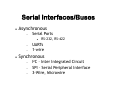
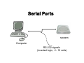
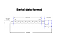
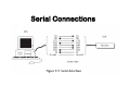
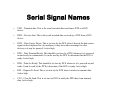
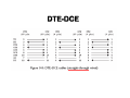
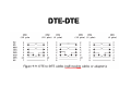
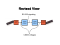
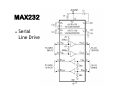
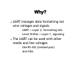
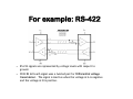
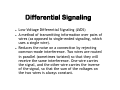
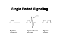
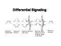
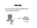
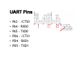
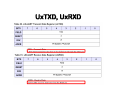
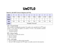
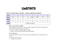
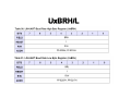
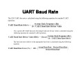
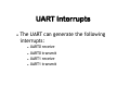
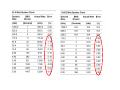
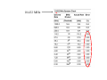
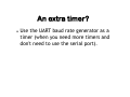
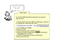
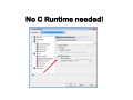
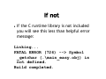
Serial Ports Real Time Embedded Systems www.atomicrhubarb.com/embedded Lecture 1 – January 17, 2012 Topic Section Topic • Where in the books – Catsoulis chapter/page – Simon chapter/page – Zilog UM197 (ZNEO Z16F Series Flash Microcontroller Contest Kit User Manual) – Zilog UM171 (ZiLOG Developer Studio II—ZNEO User Manual) – Zilog PS220 (ZNEO Z16F Series Product Specification) – Zilog UM188 (ZNEO CPU Core User Manual) – Assorted datasheets Serial Interfaces/Buses Asynchronous Serial Ports RS-232, RS-422 UARTs 1-wire Synchronous I2C – Inter Integrated Circuit SPI – Serial Peripheral Interface 3-Wire, Microwire What do we mean by “Synchronous” and “Asynchronous”? Serial Ports Modem Computer RS-232 signals (inverted logic, +/- 12 volts) Serial Ports RS-232 signaling Level Adjust Level Adjust Modem Microcontroller CMOS voltages (5 volts) Serial data format Frame Device RS-232 intended for connecting Terminals to Modems. DTE – Data Terminal Equipment DCE – Data Communication Equipment Serial Connections Serial Signal Names TXD – Transmit data. This is the serial encoded data sent from a DTE to a DCE device. RXD – Receive data. This is the serial encoded data received by a DTE from a DCE device. DCD – Data Carrier Detect. This is set true by the DCE when it detects the data carrier signal on the telephone line (for modems; it may have other meanings for other devices or it may be ignored). Active high. DTR – Data Terminal Ready. This should be set true by a DTE whenever it is powered on and ready to communicate. It can be read by the DCE to determine that the DTE is ready. Active high. DSR – Data Set Ready. This should be set true by DCE whenever it is powered on and ready. It can be read by the DTE to determine if the DCE is ready. Active high. RTS – Request To Send. This is set true by the DTE when it wishes to transmit data. Active high. CTS – Clear To Send. This is set true by DCE to notify the DTE that it can transmit data. Active high. DTE-DCE DTE-DTE Revised View RS-232 signaling UART Level Adjust Level Adjust CMOS voltages UART UART Universal Asynchronous ReceiverTransmitter, the component that handles asynchronous serial communication. Asynchronous - Not synchronized. Data is transmitted without an accompanying clock signal. UART The UART takes bytes of data and transmits the individual bits in a sequential fashion. Provides additional circuits for control signals that can be used to indicate the state of the transmission media (status), and to regulate the flow of data (handshake). UART Formatting includes adding of START and STOP bits, managing Parity, managing Baud Rate. UART does not do the level shifting. UART Summary Data is formatted by UART UART manages data Transmit and Receive UART manages handshake and status Level Shifter is required to get to/from RS-232 levels from/to CMOS logic levels. Level Shifters RS232C, requires negative logic, i.e., logic '1' is -3V to -12V and logic '0' is +3V to +12V. To convert a CMOS logic levels (TxD and RxD) from the microcontroller we need a converter chip (serial line driver). A MAX232 is one chip that is common. There are many. MAX232 Serial Line Driver Why is the level shifting not done in the UART? Why? UART manages data formatting not wire voltages and signals. UART = Layer 2, formatting bits Level Shifter = Layer 1, signaling The UART can be used with other media and line voltages like RS-422 (twisted pair) and IrDA. For example: RS-422 RS 232 signals are represented by voltage levels with respect to ground. With RS 422 each signal uses a twisted pair for 'Differential voltage transmission'. The signal is inactive when the voltage at A is negative and the voltage at B is positive. What is differential signaling and why do we need it? Differential Signaling Low-Voltage Differential Signaling (LVDS) A method of transmitting information over pairs of wires (as opposed to single-ended signaling, which uses a single wire). Reduces the noise on a connection by rejecting common-mode interference. Two wires are routed in parallel (sometimes twisted) so that they will receive the same interference. One wire carries the signal, and the other wire carries the inverse of the signal, so that the sum of the voltages on the two wires is always constant. Single Ended Signaling noise Signal as Transmitted Signal on the wire with noise Signal as received Differential Signaling Signal as Transmitted Signal on the wire Signal on the wire with noise Receiver adds signal to inverse of signal. Noise is canceled. Signal as received Differential Signaling USB RS-422, RS-485 Ethernet (on Cat 5) Controller Area Network (used in industrial and automotive applications) Serial Things Modems Bluetooth radios GPS Receivers Electronic Test Equipment (meters) Cell Phones ... lots of stuff RS-232 All consumer grade equipment has level shifters built-in. Modem Computer Embedded Systems Embedded systems don't need to use level shifters at all (provided the serial connection is short enough, like a few inches of wire). UART UART CMOS voltages ZNEO UART 2 UARTS in the Z16 (U0 and U1) Fully configurable (ie: lots of registers) 8-bit asynchronous data transfer Selectable even- and odd-parity generation and checking Option of one or two Stop bits Separate transmit and receive interrupts Framing, parity, overrun and break detection Separate transmit and receive enables Selectable 9-bit multiprocessor (9-bit) mode 16-bit Baud Rate Generator (BRG) LIN-UART Called the LIN-UART (Local Interconnect Network UART) Supports LIN protocol. What is LIN? LIN LIN (Local Interconnect Network) LIN bus is an low cost serial protocol LIN is a broadcast serial network comprising one master and many (up to 16) slaves. No collision detection exists, therefore all messages are initiated by the master with at most one slave replying for a given message identifier. LIN It is particularly intended for mechatronic nodes in distributed automotive applications, but is also suited to industrial applications. It is intended to complement the existing CAN network leading to hierarchical networks within cars. The ZNEO kit as 2 serial ports. Whats the difference between them? DTE DCE ZNEO UART UART modes Transmitting Data using Polled Method Transmitting Data, Interrupt Driven Method Receiving Data using Polled Method Receiving Data, Interrupt Driven Method Receiving Data using the Direct Memory Access Controller (DMA) Multiprocessor Mode LIN mode UART Pins • • • • • • PA3 - /CTS0 PA4 - RXD0 PA5 - TXD0 PD6 - /CTS1 PD4 – RXD1 PD5 - TXD1 What about the other serial port control lines? • Like DTR, DSR, CDC, RI ... UART Registers U0TXD – Data to be transmitted U0RXD – Data received U0STAT0 – UART status U0CTL0, U0CTL1 – UART control U0BRH, U0BRL – Baud Rate U0MDSTAT – Mode Select and Status U0ADDR – LIN address U1* UxTXD, UxRXD UxCTL0 UxSTAT0 UxBRH/L UART Baud Rate UART Interrupts The UART can generate the following interrupts: UART0 UART0 UART1 UART1 receive transmit receive transmit Why would you want to get an interrupt on transmit? Recall that the clock is 18.432 MHz • Why that odd frequency, not something simple like 18 MHz? 18.432 MHz 0 0 0 0 0 0 0 0 0 0 Don't forget ... Don't forget to enable the Alternate Function on port A or D for UAR0 or UART1, or there will be no data received or transmitted No Multiprocessor or LIN mode discussion! UART polled transmit recipe Polled Transmit 1. Set baud rate (UxBRH/L) 2. Enable UART pin functions (UxCTL0,1) 3. Enable parity if desired (PEN and PSEL bits in UxCTL0) 4. Enable UART by setting TEN bit in UxCTL0 5. Set alternate function on GPIO pins 6. Set or clear CTSE bit in UxCTL0 to enable flow control on the /CTS pin 7. When TDRE bit in UxSTAT0 is set (1) then the transmit buffer is empty, write one byte to UxTXD to send byte. Repeat this step until all bytes have been sent. UART polled receive recipe Polled Receive 1. Set baud rate (UxBRH/L) 2. Enable UART pin functions (UxCTL0/1) 3. Enable parity if desired (PEN and PSEL bits in UxCTL0) 4. Set alternate function on GPIO pins 5. Enable UART by setting REN bit in UxCTL0 6. When RDA bit in UxSTAT0 is set (1) then the transmit buffer is full, read one byte from UxRXD to get byte. Repeat this step until all bytes have been received. UART interrupt transmit recipe Interrupt Transmit 1. Set baud rate (UxBRH/L) 2. Enable UART pin functions (UxCTL0/1) 3. Disable interrupts 4. Enable UARTx transmitter interrupts by writing to the Interrupt control registers. 5. Enable UART by setting TEN bit in UxCTL0 6. Set alternate function on GPIO pins 7. Enable parity if desired (PEN and PSEL bits in UxCTL0) 8. Set or clear CTSE bit in UxCTL0 to enable flow control on the /CTS pin 9. Enable interrupts 10. Write your ISR 11. ISR should write byte to UxTXD and then clear the UART transmit bit in the Interrupt Control register 12. Assign the ISR vector. UART interrupt receive recipe Receive Transmit 1. Set baud rate (UxBRH/L) 2. Enable UART pin functions (UxCTL0/1) 3. Disable interrupts 4. Enable UARTx receiver interrupts by writing to the Interrupt control registers. 5. Enable UART by setting REN bit in UxCTL0 6. Set alternate function on GPIO pins 7. Enable parity if desired (PEN and PSEL bits in UxCTL0) 8. Enable interrupts 9. Write your ISR 10. ISR should check the UxSTAT0 byte to see if there are any errors. If not, write byte to UxRXD and then clear the UART receive bit in the Interrupt Control register 11. Assign the ISR vector. An extra timer? Use the UART baud rate generator as a timer (when you need more timers and don't need to use the serial port). UART Timer Recipe UART Timer To use the UART Baud Rate Generator as a general purpose timer: 1. Disable UART (clear the REN and TEN bits in UxCTL0) 2. Compute the 16 bit baud rate value 3. Load UxBRH and UxBRL 4. Write your ISR 5. Set the interrupt vector (UARTx receive) 6. Enable the baud rate generator timer and interrupt by setting BIRQ bit in UxCTL1 7. Do NOT set alternate function on GPIO pins! 8. Enjoy the extra timer First Example Demonstrate how to send and receive characters by controlling the UART Example_ SerialHard No C Runtime needed! See, it works! Note: - 57600 - No flow control UART functions Fortunately <stdio.h> and <sio.h> help with all/most of this. sio.h stdio.h stdio.h Another Example Demonstrate how to send and receive characters by using sio.h and stdio.h (who control the UART for us) Example_ SerialSimple This Time ... If not If the C runtime library is not included you will see this less than helpful error message: Linking... FATAL ERROR (724) --> Symbol _getchar (.\main_easy.obj) is not defined. Build completed. Last Word (on serial ports) The Serial Port overview, was the “light-n-fluffy” version. For much more detailed information: http://www.beyondlogic.org/serial/serial.htm http://www.tldp.org/HOWTO/SerialHOWTO.html http://www.lvr.com/serport.htm ... Why might you (the student) want to implement a serial receive function that uses interrupts on receipt of data?