1
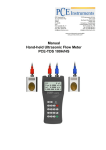
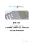
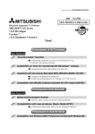
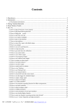
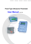
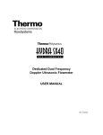
AMI
Ultrasonic Flowmeter:
Installation and User Manual
Version 1.1
AMI
Table of Contents
Section 1: Getting Started ..................................................................................................................3
1.1
Things to know ....................................................................................................................3
1.2
Transducer site requirements...............................................................................................3
1.3
Using the keys .....................................................................................................................5
Section 2: Mounting the Transducers..................................................................................................5
2.1
Choose mounting method ....................................................................................................5
2.2
Preparing pipe surface .........................................................................................................5
2.3
Preparing the transducer......................................................................................................5
V-Method Installation..................................................................................................................6
Z-Method Installation ..................................................................................................................6
W- Method Installation................................................................................................................6
Section 3: Necessary Measurements...................................................................................................7
Section 4: Fine Tuning and Troubleshooting........................................................................................8
4.1
Setting Your Zero Point ........................................................................................................8
4.2
Fine Tuning..........................................................................................................................8
4.3
Manual Totalizer Reset.........................................................................................................8
4.4
Troubleshooting ..................................................................................................................9
Appendix A: Menu Screens...............................................................................................................10
Ultrasonic Flowmeter: Installation and User Manual
Version 1.1
Page 2
Kit Includes:
1 – AMI Enclosure
1 – Ultrasonic Flowmeter
2 – Transducers (4’ cable)
2 – 4” Clamps
2 – 6” Clamps (Join together w/4” if using on larger pipe)
1 – Tube synthetic grease
Section 1: Getting Started
Please read through this entire section before installing your Ultrasonic Flowmeter for the first time.
1.1
Things to know
All setup parameter data is stored temporarily in RAM. To make changes permanent, you
must save your changes in menu Screen 26. Any changes not stored by this method will be
lost upon device reboot.
To obtain the most accurate readings, device must first be calibrated with zero flow through
the pipe (zero point). This reading can be set as the zero point in Menu Screen 42 (M42).
The size of the pipe will determine the best transducer mounting method. Refer to section 3
for best mounting methods.
It is recommended to fill out the form in section 2 prior to bringing the unit to the field to be
installed. You can also preset the information into the device prior to installing to save time.
All setup parameter data is stored temporarily in RAM. To make changes permanent, you
must save your changes in menu Screen 26. Any changes not stored by this method will be
lost upon device reboot.
1.2
Transducer site requirements
The following conditions must be met to have valid and usable data from the Ultrasonic
Flowmeter. If any or all of the conditions do not meet the requirements, the meter will not
function properly.
Pipe must be full of liquids at time of reading
No heavy corrosion or deposition inside of pipe
Must be in safe and secure location
As a general rule, the pipe must not be shorter than 15xdiameter. Insufficient straight pipe
length will degrade the accuracy.
The mounting site for the transducers should be 10D upstream and 5D downstream
If there are flow disturbing parts (such as pumps, valves, etc) upstream, the straight pipe
length should be increased
Ultrasonic Flowmeter: Installation and User Manual
Version 1.1
Page 3
Ultrasonic Flowmeter: Installation and User Manual
Version 1.1
Page 4
1.3
Using the keys
Menu – used for entering into various menu windows
Page up – used for advancing menu windows, and for adding digits
Page down – use to move cursor into next digit position
Enter – use to enter selection
Example – to enter menu window 26, the user would press:
x1
x2
x1
x6
x1
Section 2: Mounting the Transducers
The transducers can be attached using three different methods:
2.1
Choose mounting method
The size of the pipe will determine the best method to mount your transducers. Generally, for
pipes over 4” you want to use the Z-Method
2.2
Preparing pipe surface
The pipe surface where the transducers will be mounted should be clean and free from any rust,
paint and moisture. A dry, clean surface will ensure a good acoustic bond between transducers
and the pipe.
2.3
Preparing the transducer
Clean and dry the transducer contact surface. Apply synthetic grease on transducer where it will
contact the pipe. Do not apply more grease than necessary, especially on smaller pipes.
If installing on a horizontal pipe, the transducers should be mounted on the sides of
the pipe to minimize air bubbles interfering with the signal quality!
Ultrasonic Flowmeter: Installation and User Manual
Version 1.1
Page 5
V-Method Installation
The V-Method is most commonly used for pipe diameters ranging from ¾” to 8” and is also referred to
as Reflective Mode.
Z-Method Installation
The Z-Method can be used for pipe sized ranging from 4” to 23 ½”. We recommend using the Z method
when the pipe is 4” or greater.
W- Method Installation
The W-Method is most widely used on smaller pipes, ½” to 1 ¾” in size.
Ultrasonic Flowmeter: Installation and User Manual
Version 1.1
Page 6
Section 3: Necessary Measurements
The following sheet contains the basic information necessary to setup your Ultrasonic Flowmeter. It is
recommended the user fills out completely as much information ahead of time as possible. You can
either fill out this form, or enter the necessary data directly into the flow meter.
Parameter
Menu
Screen
Note
Pipe Outer Diameter
11
Pipe Wall Thickness
12
Pipe Inner Diameter
13
Pipe Materials*
14
Liner Material and its sound speed and thickness (if any)
16
Liquid type*
20
Transducer type connected to flow meter
23
Transducer mounting method (See section 2)
24
Transducer spacing (Will be displayed in screen 24)
25
Measurements in Units
30
Set to English
Flow Rate Units
31
Set to g/m or GPM
Default Settings†
26
1. Solidify Settings
View Data
00
To obtain flow readings
Clamp on L2
* Standard pipe materials and standard liquids refer to those with the sound parameters that have
already been programmed into the flow meter software. Non standard pipe materials and non standard
liquids will need the sound speed configured.
† You must store the settings when completed or the unit will reset to default settings upon startup
Ultrasonic Flowmeter: Installation and User Manual
Version 1.1
Page 7
Section 4: Fine Tuning and Troubleshooting
4.1
Setting Your Zero Point
If possible, stop all flow running through the pipe while maintaining a pipe full of liquid.
Parameter
Set Zero
4.2
Menu
Screen
42
Note
Zero calibration/Zero Point Setup
Fine Tuning
For the flow meter readings to be considered accurate, you must confirm the data in two menu
screens.
Parameter
Menu
Screen
Signal Strength + Quality
90
Transit Time Ratio
Tips:
91
Note
Poor <60
Optimal 60-99
Poor >90
100% +/-3%
If necessary, move transducers closer to, or further from, each other to increase or decrease
the values in screen 91
Make sure the transducer mounting area on the pipe is coating free and smooth.
4.3
Manual Totalizer Reset
Should you want to reset the totalizer values you can do so in Menu 37. You can use a
calibration totalizer on Menu 38.
Parameter
Totalizer Reset
Manual Totalizer
Ultrasonic Flowmeter: Installation and User Manual
Version 1.1
Menu
Screen
37
38
Note
Reset All
Use for manual calibration of flow
Page 8
4.4
Troubleshooting
If you are unable to get a flow reading, or if your values in screens 90 and 91 are not within their
thresholds:
Is the pipe too old?
Too much corrosion?
Too many air bubbles?
Is the pipe full?
Are your parameters correct?
Are the transducers located too close to the pump, valve or elbow in the pipe?
Is the transducer spacing correct (menu screen 24)
Ultrasonic Flowmeter: Installation and User Manual
Version 1.1
Page 9
Appendix A: Menu Screens
Menu
window No.
Function
Display flow rate and NET totalizer
M00
If the net totalizer is turned off, the net totalizer value shown on the screen is the value
prior to its turn off
Select all totalizer unit in menu M31
M01
Display flow rate, velocity
Display date time and POS(positive) totalizer
M02
If the positive totalizer is turned off, the positive totalizer value shown on the screen is
the value prior to its turn off
Display flow rate and NEG(negative) totalizer
M03
If the negative totalizer is turned off, the negative totalizer value shown on the screen is
the value prior to its turn off
M04
Display date and time, flow rate. The date and time setting method is found in MENU60
M05
Display energy rate(instantaneous Caloric)and total energy (Caloric)
M06
Display temperatures, inlet T1, outlet T2
M07
Display analog inputs, AI3/AI4, current value and its corresponding temperature or
pressure or liquid level value
Display all the detailed error codes
M08
Display working condition and system error codes. ‘R’ stands for normal, others refer to
Chapter 8 for details.
M09
Display today’s total NET flow
M10
Window for entering the outer perimeter of the pipe. If pipe outer diameter is known,
skip this menu and go to Menu 11 to enter the outer diameter
Ultrasonic Flowmeter: Installation and User Manual
Version 1.1
Page 10
Window for entering the outer diameter of the pipe. Valid range:0 to 18000mm.
M11
Note: you just need to enter either the outer diameter in M11 or the peripheral in M10
Window for entering pipe wall thickness
M12
You may skip the menu and enter inner diameter in M13 instead.
Window for entering the inner diameter of the pipe
M13
If pipe outer diameter and wall thickness are enter correctly, the inner diameter will be
calculated automatically, thus no need to change anything in the window
Window for selecting pipe material
Standard pipe materials (no need to enter material sound speed ) include:
M14
(0) carbon steel (1) stainless steel (2) cast iron (3) ductile iron (4) copper
(6) aluminum ,(7) asbestos (8) fiberglass
(5) PVC
(9) other( need to enter material sound speed in M15)
M15
Window for entering the pipe material speed, only for non-standard pipe materials
Window for selecting the liner material, select none for pipes without any liner.
Standard liner materials(no need to enter the liner sound speed) include:
M16
(1) Tar Epoxy (2) Rubber (3) Mortar (4) Polypropylene (5) Polystryol (6)Polystyrene (7)
Polyester (8) Polyethylene (9) Ebonite (10) Teflon
(11) Other (need to enter liner sound speed in M17)
M17
Window for entering the non-standard liner material speed.
M18
Window for entering the liner thickness, if there is a liner
M19
Window for entering the ABS thickness of the inside wall of the pipe
Window for selecting fluid type
M20
For standard liquids(no need to enter fluid sound speed) include:
(0) Water
(1) Sea Water (2) Kerosene
Ultrasonic Flowmeter: Installation and User Manual
Version 1.1
Page 11
(3) Gasoline (4) Fuel oil
(5) Crude Oil
(6) Propane at -45C (7) Butane at 0C
(8)Other liquids(need to enter sound speed in M21 and viscosity in M22) (9) Diesel Oil
(10)Caster Oil
(11)Peanut Oil (12) #90 Gasoline (13) #93 Gasoline (14) Alcohol (15)
Hot water at 125C
M21
Window for entering the sound speed of non- standard liquid, used only when option
item 8 ‘Other’ is selected in M20
M22
Window for entering the viscosity of the non-standard liquids, used only when option
item 8 ‘Other’ is selected in M20
Window for selecting transducer type, There are 22 types as following
M23
0.
Standard M
1.
2.
Insertion Type C
Standard S
3.
User Type
4.
5.
Standard B
Insertion Type B(45)
6.
Standrad L
7.
8.
JH-Polysonics
Standard-HS
9.
Standard-HM
10. Standard-M1 (middle M1 transducer)
11. Standard-S1 (small S1 transducer)
12. Standard-L1 (large L1 transducer)
13. PI-Type
14. FS410
15. FS510
16. Clamp-on TM-1
17. Insertion TC-1
18. Calmp-on TS-1
19. Reserved
20. Clamp-on TL-1
Ultrasonic Flowmeter: Installation and User Manual
Version 1.1
Page 12
21. Insertion TLC-2
If the user-type-transducer is selected, you need enter additional 4 user-type-wedge
parameters that describe the user transducers.
If the PI-type transducer is selected, you need enter additional 4 PI-type transducer
parameters that describe the PI-type transducers
Window for selecting the transducer mounting methods
M24
Four methods can be selected:
(0) V-method (1) Z-method (2) N-method (3) W-method
M25
Display the transducer mounting spacing or distance
M26
(1) A switch for the parameters in flash memory will be loaded when power is turned on.
The default option is that the parameters will be loaded. If this switch is not turned
on, the system will try to use the parameters in the system RAM, if these parameters
are ok, otherwise the system will load the parameters in flash memory
(2) Function to store the current parameters into the flash memory, so that these
parameters will be solidified and will be loaded as the default parameters every time
when power is turned on.
Entry to store to or restore from the internal Flash memory, as many as 9 different pipe
parameter configurations
M27
M28
To save or load the current setup parameter, use the going up or going down keys to
change the address number, press ‘ENT’ key, and use going down or going up keys to
select to save to or load from the memory.
Entry to determine whether or not to hold (or to keep) the last good value when poor
signal condition occurs. YES is the default setup.
Entry to setup empty signal threshold. When the signal is less than this threshold, the
pipe is regarded as empty pipe, and the flow meter will not totalize flow.
M29
This is based on the fact that, for most occasions, when pipe is empty, the transducer
would still receive signal, just smaller than normal, As a result, The flow meter would
show normal operation, which is not correct.
Make sure that the entered value must be less than the normal signal strength.
When much noisy signals are received, to make sure the flow meter will not incorrectly
Ultrasonic Flowmeter: Installation and User Manual
Version 1.1
Page 13
totalize flow, there is also a ‘Q’ threshold should be entered in M.5
M30
Window for selecting unit system. The conversion English to Metric or vice versa will not
affect the unit for totalizers.
Window for selecting flow rate unit system.
Flow rate can be in
0. Cubic meter short for (m3)
M31
1. Liter
2. USA gallon
(l)
(gal)
3. Imperial Gallon
(igl)
4. Million USA gallon
5. Cubic feet
(mgl)
(cf)
6. USA liquid barrel
(bal)
7. Oil barrel
(ob)
The flow unit in terms of time can be per day, per hour, per minute or per second. So
there are 32 different flow rate units in total for selection.
M32
Window for selecting the totalizers unit. Available units are the same as those in M31
Window for setting the totalizer multiplying factor
M33
The multiplying factor ranges from 0.001 to 10000. Factory default is 1
M34
Turn on or turn off the NET totalizer
M35
Turn on or turn off the POS (positive) totalizer
M36
Turn on or turn off the NEG(negative) totalizer
(1) Totalizer reset
M37
M38
(2) Restore the factory default settings parameters. Press the dot key followed by the
backspace key. Attention, It is recommended to make note on the parameters before
doing the restoration
Manual totalizer used for easier calibration. Press a key to start and press a key to stop
the manual totalizer.
Ultrasonic Flowmeter: Installation and User Manual
Version 1.1
Page 14
Interface Language selection.
M39
M40
The selection could also be changed automatically by the system, if English LCD display is
used as the display device.
Flow rate damper for a stable value. The damping parameter ranges form 0 to 999
seconds.
0 means there is no damping. Factory default is 10 seconds
M41
Low flow rate (or zero flow rate) cut-off to avoid invalid accumulation.
M42
Zero calibration/Zero point setup. Make sure the liquid in the pipe is not running while
doing the setup.
M43
Clear the zero point value, and restore the solidified zero point value.
M44
Set up a flow bias. Generally this value should be 0.
M45
Flow rate scale factor. The default value is ‘1’.
Keep this value as ‘1’, when no calibration has been made.
Networks address identification number. Any integer can be entered except 13(0DH,
carriage return), 10 (0AH, line feeding), 42 (2AH), 38, 65535.
M46
Every set of the instrument in a network environment should have a unique IDN. Please
refer to the chapter for communication.
System locker to avoid modification of the system parameters.
M47
M48
If password is forgotten, you could send a command ‘LOCK0’ to the serial input to unlock.
Or you can write 0 to REGISTER49-50 under MODBUS protocol.
Entry to linearity correcting data inputs. By using of this function, the non-linearity of flow
meter will be corrected. Correcting data shall be obtained by careful calibration.
Displays the input contents for the serial port.
M49
M50
By checking the displays, you can know if the communication is ok.
Switches for the built-in data logger. There are as many as 22 different items can be
chosen. To turn this function, select ‘YES’ the system will ask for selecting the items.
Ultrasonic Flowmeter: Installation and User Manual
Version 1.1
Page 15
There are 22 items available. Turn on all those items you want to output
M51
Window to setup the time of scheduled output function (data logger, or Thermo-printer).
This includes start time, time interval and how many times of output. When a number
great than 8000 entered for the times of output, It means the output will be keeping
always. The minimum time interval is 1 second and the maximum is 24 hours.
Data logging direction control.
M52
(1) If ‘Send to RS485’ is selected, all the data produced by the data logger will be
transmitted out through the RS-232/RS485 interface
(2) If ‘To the internal serial BUS is selected, the data will be transmitted to the internal
serial bus which allows a thermal printer, or a 4-20mA analog output module, to be
connected to it.
M53
Display analog inputs, AI5, current value and its corresponding temperature or pressure
or liquid level value.
M54
Pulse width setup for the OCT (OCT1) output. Minimum is 6 mS, maximum is 1000 mS
Select analog output (4-20mA current loop, or CL) mode. Available options:
(0) 4-20mA output mode (setup the output range from 4-20mA)
(1) 0-20mA output mode (setup the output range from 4-20mA, This mode can only be
used with Version-15 flow meter)
(2) Serial port controls 0-20mA
M55
(3) 4-20mA corresponding fluid sound speed
(4) 20-4-20mA mode
(5) 0-4-20mA mode (can only be used with Version-15 flow meter)
(6)20-0-20mA mode(can only be used with Version-15 flow meter)
(7) 4-20mA corresponding flow velocity
(8)4-20mA corresponding heat flow rate
M56
4mA or 0mA output value,
Set the value which corresponds to 4mA or 0mA output current (4mA or 0mA is
Ultrasonic Flowmeter: Installation and User Manual
Version 1.1
Page 16
determined by the setting in M55)
20mA output value,
M57
Set the value which corresponds to 20mA output current
Current loop verification
M58
Check if the current loop is calibrated correctly.
M59
Display the present output current of current loop circuit.
M60
Setup system date and time. Press ENT for modification. Use the dot key to skip the digits
that need no modification.
M61
Display Version information and Electronic Serial Number (ESN) that is unique for each
flow meter.
The users may employ the ESN for instrumentation management
RS-232/RS485 setup. All the devices connected with flow meter should have matched
serial configuration.
M62
The following parameters can be configured: Baud rate (300 to 19200 bps), parity, data
bits (always is 8), stop bits
Select communication protocol.
M63
Factory default is ‘MODBUS ASCII. this is a mode for MODBUS-ASCII, Meter-BUS, Fuji
Extended Protocol
If you are going using MODBUS-RTU you have to select ‘MODBUS_RTU’.
AI3 value range.
M64
Used to enter temperature/pressure values that are corresponding to 4mA and 20mA
input current. The display values have no unit, so that they can present any physical
parameter.
AI4 value range.
M65
Used to enter temperature/pressure values that are corresponding to 4mA and 20mA
input current.
Ultrasonic Flowmeter: Installation and User Manual
Version 1.1
Page 17
AI5 value range.
M66
Used to enter temperature/pressure values that are corresponding to 4mA and 20mA
input current.
Windows to setup the frequency range (lower and upper limit) for the frequency output
function. Valid range is 0Hz-9999Hz. Factory default value is 0-1000 Hz.
M67
For Version-12, Version-13, Version-14 flow meters, you need a hardware module, which
shall be plugged to the Serial Expanding Bus, for the frequency output function. Please
remember to order the module if you need frequency output function.
For Version-15 flow meter, you need to indicate on your orders that you need the
frequency function; Otherwise you will get a flow meter which has no frequency output
circuits.
M68
Window to setup the minimum flow rate value which corresponds to the lower frequency
limit of the frequency output.
M69
Windows to setup the maximum flow Rate value that corresponds to the upper frequency
limit of the frequency output.
M70
LCD display backlight control. The entered value indicates how many seconds the
backlight will be on with every key pressing. If the enter value is great than 50000
seconds, It means that the backlight will always keeping on.
M71
LCD contrast control. The LCD will become darker or brighter when a value is entered.
M72
Working timer. It can be cleared by pressing ENT key, and then select YES.
M73
Window to setup the lower limit of flow rate for Alarm#1.
When the flow rate is below the set value, Alarm#1 equals ‘on’
Window to setup the upper limit of flow rate for Alarm#1.
When the flow rate is above the set value, Alarm#1 equals ‘on’
M74
M75
There are two alarms in the flow meter, and every alarm can be pointed to alarm output
devices such as the BUZZER or OCT output or RELAY output. For example, if you want the
Alarm#1 is to output by the OCT circuit, you need to set M78 at selection item 6.
Window to setup the lower limit of flow rate for Alarm#2.
Ultrasonic Flowmeter: Installation and User Manual
Version 1.1
Page 18
M76
Window to setup the upper limit of flow rate for Alarm#2.
Buzzer setup.
If a proper input source is selected, the buzzer will beep when the trigger event occurs.
The available trigger sources are:
0. No Signal
1. Poor Signal
2. Not Ready (No*R)
M77
3. Reverse Flow
4. AO Over 100%
5. FO Over 120%
6. Alarm #1
7. Reverse Alarm #2
8. Batch Control
9. POS Int Pulse
11.NET Int Pulse
12.Energy POS Pulse 13.Energy NEG Pulse
10.NEG Int Pulse
14.Energy NET Pulse 15.MediaVel=>Thresh 16.MediaVelo<Thresh
17.ON/OFF viaRS232 18.Daily Timer (M51) 19.Timed alarm #1
20. Timed alarm #2
21.Batch Totalizer Full 22. M51 Timer
23. Key Stroking ON 24.Disable BEEPER
OCT (Open Collect Transistor Output)/OCT1 setup
By selecting a proper input source, the OCT circuit will close when the trigger event
occurs. The available trigger sources are:
0. No Signal
1. Poor Signal
2. Not Ready(No*R) 3. Reverse Flow
5. FO Over 120% 6. Alarm #1
M78
8. Batch Control
9. POS Int Pulse
4. AO Over 100%
7. Reverse Alarm #2
10.NEG Int Pulse
11.NET Int Pulse 12.Energy POS Pulse 13.Energy NEG Pulse
14.Energy NET Pulse 15.MediaVel=>Thresh 16.MediaVelo<Thresh
17.ON/OFF viaRS232 18. Daily Timer (M51) 19.Timed alarm #1
20. Timed alarm #2
21.Batch Totalizer Full
22. Periodically M51 Timer 23. Oct Not Using
Ultrasonic Flowmeter: Installation and User Manual
Version 1.1
Page 19
The OCT circuit does not source voltage at its output. It must be connected with an
external power and pull-up resistant for some occasions.
When the OCT circuit is close, it will draw current. The maximum current shall not be over
100mA.
Attention: the maximum voltage applied to OCT can not be over 80 volts.
Relay or OCT2 setup
By selecting a proper input source, the RELAY will close when the trigger event occurs
The available trigger sources are:
0. No Signal
1. Poor Signal
2. Not Ready(No*R) 3. Reverse Flow
M79
4. AO Over 100%
5. FO Over 120%
6. Alarm #1
7. Reverse Alarm #2
8. Batch Control
9. POS Int Pulse 10.NEG Int Pulse
11.NET Int Pulse
12.Energy POS Pulse 13.Energy NEG Pulse
14.Energy NET Pulse 15.MediaVel=>Thresh 16.MediaVelo<Thresh
17.ON/OFF viaRS232 18. Timer (M51 Daily) 19.Timed alarm #1
20. Timed alarm #2
21.Batch Totalizer Full
22. Periodically M51 Timer 23. Disable Relay
The RELAY is of SPST(Single pole, single throw) type. It is rated for 110VAC max and have
a current rating of 0.5A resistive load.
It highly recommended that a salve relay to be utilized whenever a large resistive load or
inductive load is to be controlled.
Note. In order to make the user interface compatible with the former version7, the name
RELAY was used other than OCT2, but in fact it is an OCT output.
Window for selecting the trig signal for the built-in batch controller. Available trig
sources:
M80
0. Key input
(press ENT key to start the batch controller)
1. Serial port
Ultrasonic Flowmeter: Installation and User Manual
Version 1.1
Page 20
2. AI3 rising edge
(when AI3 receives 2mA or more current)
3. AI3 falling edge
4. AI4 rising edge
(when AI3 stop receiving 2mA or more current)
(when AI3 receives 2mA or more current)
5. AI4 falling edge (when AI3 stop receiving 2mA or more current)
6. AI5 rising edge
(when AI3 receives 2mA or more current)
7. AI5 falling edge (when AI3 stop receiving 2mA or more current)
8.Timer periodically (define the start time and interval time in M51)
9.Timer daily
(define the start time and interval time in M51)
For the input analog current signal, 0 mA indicates “0”, 4mA or more indicates ‘1’.
By selecting item #8, the batch totalizer can be started periodically by the internal timer
located at Menu51. When the batch totalizer is full, a signal which indicate the batch is
full can be direct to either the OCT or the RELAY terminals to stop the pump or other
devices.
By selecting item #9, the batch totalizer could act as totalizer which runs for only a period
of the day so that a alarm signal could be produced if the total flow during that time
period is over a certain amount of. For example, if you want a alarm signal which stand
for the total flow is over 100 cubic meters during the pe riod of every day from 20:00 to
06:00, setups is like
M51 start time =20:00:00
M51 interval =10:00:00
M51 log times =9999 (means always)
M80 select item #9
M81 input 100
(Unit is defined in M30,M31,M32)
The built-in batch controller
Set the flow batch value(dose)
M81
The internal output of the batch controller can be directed either to the OCT or the RELAY
output circuits.
M81 and M80 should be used together to configure the batch controller.
Ultrasonic Flowmeter: Installation and User Manual
Version 1.1
Page 21
Note: Because the measuring period is 500mS, the flow for every dos should be keeping
at 60 seconds long to get a 1% dose accuracy.
View the daily, monthly and yearly flow totalizer and thermal energy totalizer value.
M82
The totalizer values and errors for the last 64 days, 32 last 32 months and last 2 years are
stored in the RAM memory, To view them, use the ‘ENT’ and ‘UP’ ‘Down’ keys.
Automatic Amending Function for automatic offline compensation.
Select ‘YES’ to enable this function, select ‘NO’ to disable it.
M83
When the function is enabled, The flow meter will estimate the average flow uncounted
(or ‘lost’) during the offline session and add the result to the totalizer.
The estimation of the uncounted flow is made by computing the product of the offline
time period and the average flow rate, which is the average of the flow rate before going
offline and the one after going on line.
Set the thermal energy unit:
M84
0. GJ 1. KC
2.KWh
3. BTU
Select temperature sources
M85
0.
from T1,T2 (factory default)
1.
from AI3,AI4
Select the Specific Heat Value.
M86
Factory default is ‘GB’. Under this setting, the flow meter will calculate the enthalpy of
water based on the international standard.
If the fluid is other than water, you should select option ‘1. Fixed Specific Heat’, and enter
the specific heat value of the fluid.
M87
Turn on or turn off the Energy totalizer.
Select thermal energy totalizer multiplying factor.
M88
M89
Factory default is ‘1’.
1. Display the temperature difference
Ultrasonic Flowmeter: Installation and User Manual
Version 1.1
Page 22
2. Window for entering the lowest temperature difference.
Display signal strengths S (one for upstream and one for downstream), and signal quality
Q value.
M90
Signal strength is presented by 00.0 to 99.9, the bigger the value, the bigger the signal
strength will be, and more reliable readings will be made.
Q value is presented by 00 to 99, the bigger the better. It should at least be great than 50
for normal operations.
M91
Displays the Time Ratio between the Measured Total Transit Time and the Calculated
time. If the pipe parameters are entered correctly and the transducers are properly
installed, the ratio value should be in the range of 100±3%. Otherwise the entered
parameters and the transducer installation should be checked.
M92
Displays the estimated fluid sound velocity. If this value has an obvious difference with
the actual fluid sound speed, pipe parameters entered and the transducer installation
should be checked again.
M93
Displays total transit time and delta time(transit time difference)
M94
Displays the Reynolds number and the pipe factor used by the flow rate measurement
program. Pipe factor is calculated based on the ratio of the line-average velocity and the
cross-section average velocity.
(1) Display the positive and negative energy totalizers
M95
(2) Upon entering this window, the circular display function will be started automatically.
The following windows will be displayed one by one, each window will stay for 8 seconds:
M95>>M00>>M01>>M02>>M02>>
M03>>M04>>M05>>M06>>M07>>M08>>M90>>M91>>M92>> M93>> M94>>M95. This
function allows the user to visit all the important information without any manual action.
To stop this function, simply press a key. Or switch to a window other than M95.
M96
This is not a window but a command for the thermal printer to advance 5 lines of paper.
This is not a window but a command to print the pipe parameters.
M97
By default, the produced data will be directed to the internal serial bus (thermal printer).
You can also direct those data to the serial communication port.
Ultrasonic Flowmeter: Installation and User Manual
Version 1.1
Page 23
This is not a window but a command to print the diagnostic information.
M98
By default, the produced data will be directed to the internal serial bus (thermal printer).
You can also direct those data to the serial communication port.
This is not a window but a command to copy the current display window. By default, the
produced data will be directed to the internal serial bus (thermal printer). You can also
direct those data to the serial communication port.
M99
M+0
M+1
By use of the window copying function, you can hardcopy very window displaying
manually by switching windows, or you can obtain the window displaying data by
communication.
Browse the 32 recorded instrument power-on and power-off date and time with the flow
rate at the time of power on and off
Displays the total working time of the flow meter.
When the backup battery is removed, the total working time will be reset to zero.
M+2
Displays the last power-off date and time
M+3
Displays the last power-off flow rate
M+4
Displays how many times of has been powered on and powered off.
A scientific calculator for the convenience of field working.
All the values are in single accuracy.
M+5
The calculator can be used while the flow meter is conducting flow measurement.
Water density and PT100 temperature can also be found in this function.
Set fluid sound speed threshold
M+6
Whenever the estimated sound speed (displayed in M92) exceeds this threshold, an
alarms signal will be generated and can transmitted to BUZZER or OCT or RELAY.
This function can used to produce an alarm or output when fluid material changes.
M+7
Displays total flow for this month(only for the time past)
M+8
Displays total flow for this year(only for the time past)
Ultrasonic Flowmeter: Installation and User Manual
Version 1.1
Page 24
M+9
Display the not-working total time in seconds. The total failure timer will also include the
time when power off, if the back-up battery is applied.
M.2
Entry to solidify the zero point. Password protected.
Setup the Q value threshold.
M.5
If the present Q is below this threshold, flow rate will be set to 0.
This function is useful when flow meter is installed in noisy environment or on airy pipes.
M.8
The maximum flow rates for today and this month.
M.9
Serial port tester with CMM command output for very second.
M-0
Entry to hardware adjusting windows only for the manufacturer
M-1
4-20mA output adjustment
M-2
4mA calibration for AI3 input
M-3
20mA calibration for AI3 input
M-4
4mA calibration for AI4 input
M-5
20mA calibration for AI4 input
M-6
4mA calibration for AI5 input
M-7
20mA calibration for AI5 input
M-8
Lower Temperature Zero setup for the PT100
M-9
Higher Temperature Zero setup for the PT100
M-A
Temperature Calibration at 50℃
M-B
Temperature Calibration at 84.5℃
Ultrasonic Flowmeter: Installation and User Manual
Version 1.1
Page 25
Section
Doc
Doc
4.2
4.3
Revisions
Revised entire document, condensing and repositioning sections
Added Kit Includes
Added Zero Flow Calibration
Added instruction for totalizer reset
Ultrasonic Flowmeter: Installation and User Manual
Version 1.1
Date
5-28-13
5-28-13
6-14-13
6-14-13
Page 26