1
Master’s Thesis Nr. 119
Systems Group, Department of Computer Science, ETH Zurich
Hardware Transactional Memory and Message Passing
by
Raphael Fuchs
Supervised by
Prof. Dr. Timothy Roscoe, Dr. Antonios Kornilios Kourtis
September 19, 2014
Abstract
Message passing has gained increased adoption. It is an integral part of programming
languages like Erlang and Go, the de-facto standard on large-scale clusters, and the
basic means of communication in the Barrelfish operating system.
This thesis focuses on point-to-point, inter-core message passing between two processes running in parallel and within a cache-coherency domain. State-of-the-art
communication in such a scenario bypasses the kernel and relies on shared memory
for message transfer, therefore providing high bandwidth communication. However, low-latency is only achieved if the receiver is constantly polling, which wastes
processor cycles that are better spent on application processing.
We describe a simple hardware mechanism, alert-on-update, that, inspired by
hardware transactional memory, monitors multiple memory locations and triggers a
control transfer upon modification. This mechanism enables the sender to notify
the receiver of a new message and, in turn, frees the receiver from constant polling.
We integrate alert-on-update into Barrelfish’s message passing framework and
describe the support needed from the operating system. Using full-system simulation,
the evaluation shows that our solution outperforms polling at regular intervals with
message latencies up to several orders of magnitude lower and, on top of that,
provides a cleaner programming construct.
Acknowledgments
First and foremost, I would like to thank Timothy Roscoe and Kornilios Kourtis
for their support and guidance. Their critical thinking and valuable input were
essential for the success of this thesis. It has been a pleasure working with you!
Thanks also belongs to the rest of the Barrelfish team, for their input and feedback
especially during our brainstorming sessions.
Additionally, I would like to thank Christine Zeller, Reto Achermann and Jonas
Moosheer for their comments and suggestions on an earlier draft of this thesis.
Contents
List of Figures
5
List of Tables
6
List of Listings
7
1 Introduction
8
2 Background
2.1 Hardware Transactional Memory . . . . . . . . . . . .
2.1.1 Intel Transactional Synchronization Extensions
2.1.2 AMD Advanced Synchronization Facility . . .
2.2 Barrelfish Operating System . . . . . . . . . . . . . . .
2.2.1 Overview . . . . . . . . . . . . . . . . . . . . .
2.2.2 Dispatchers and User-level Scheduler . . . . . .
2.2.3 User-level Message Passing (UMP) . . . . . . .
2.2.4 Flounder . . . . . . . . . . . . . . . . . . . . .
.
.
.
.
.
.
.
.
.
.
.
.
.
.
.
.
.
.
.
.
.
.
.
.
.
.
.
.
.
.
.
.
.
.
.
.
.
.
.
.
.
.
.
.
.
.
.
.
.
.
.
.
.
.
.
.
.
.
.
.
.
.
.
.
10
10
10
12
12
12
13
14
14
3 Using Intel TSX to Accelerate Message Passing
3.1 RTM Performance Analysis . . . . . . . . . . . . . .
3.1.1 Setup and Commit Overhead . . . . . . . . .
3.1.2 Abort Overhead . . . . . . . . . . . . . . . .
3.1.3 Setup, Commit and Abort Overhead Scaling
3.1.4 Time Limit . . . . . . . . . . . . . . . . . . .
3.2 Abort Handler for Message Notification . . . . . . .
3.3 Helper Threading and RTM for Message Passing . .
3.4 n : 1 communication channels . . . . . . . . . . . . .
3.5 Conclusion . . . . . . . . . . . . . . . . . . . . . . .
.
.
.
.
.
.
.
.
.
.
.
.
.
.
.
.
.
.
.
.
.
.
.
.
.
.
.
.
.
.
.
.
.
.
.
.
.
.
.
.
.
.
.
.
.
.
.
.
.
.
.
.
.
.
.
.
.
.
.
.
.
.
.
.
.
.
.
.
.
.
.
.
16
16
17
17
18
20
21
23
26
27
.
.
.
.
.
.
.
.
.
4 Using Alert-on-Update to Accelerate Message Passing
28
4.1 Alert-on-Update ISA Extension . . . . . . . . . . . . . . . . . . . . . 28
4.1.1 Enabling and Disabling Alerts . . . . . . . . . . . . . . . . . 29
4.1.2 Modify Set of Monitored Memory Locations . . . . . . . . . . 29
3
4.2
4.3
4.1.3 Alert . . . . . . . . . . . . . . . . . . . . . .
4.1.4 Implicit Disabling of Alerts . . . . . . . . .
4.1.5 Spurious Alerts . . . . . . . . . . . . . . . .
Message Passing Without Polling . . . . . . . . . .
4.2.1 Monitor Message Channel . . . . . . . . . .
4.2.2 Dedicated Memory Region for Notifications
Barrelfish Application Programmer API . . . . . .
.
.
.
.
.
.
.
.
.
.
.
.
.
.
5 Implementation
5.1 Alert-on-Update in Gem5 . . . . . . . . . . . . . . . .
5.2 Barrelfish Implementation . . . . . . . . . . . . . . . .
5.2.1 Monitoring UMP Channels . . . . . . . . . . .
5.2.2 Alert - Step-by-Step . . . . . . . . . . . . . . .
5.2.3 TLA+ Model and Model Checking . . . . . . .
5.2.4 Scheduler Activations and Why Using Alerts in
.
.
.
.
.
.
.
.
.
.
.
.
.
.
.
.
.
.
.
.
.
.
.
.
.
.
.
.
.
.
.
.
.
.
.
. . . . .
. . . . .
. . . . .
. . . . .
. . . . .
Linux is
.
.
.
.
.
.
.
.
.
.
.
.
.
.
.
.
.
.
.
.
.
30
30
31
31
32
32
33
. . .
. . .
. . .
. . .
. . .
Hard
36
36
40
40
40
43
45
6 Evaluation
47
6.1 Alerts versus Tight Polling . . . . . . . . . . . . . . . . . . . . . . . 47
6.2 Alerts versus Polling at Different Polling Frequencies . . . . . . . . . 49
6.3 Alerts versus Polling with Multiple UMP Channels . . . . . . . . . . 51
7 Related Work
53
8 Conclusion and Future Work
8.1 Directions for Future Work . . . . . . . . . . . . . . . . . . . .
8.1.1 Alert-on-Update and Fast Mutexes . . . . . . . . . . . .
8.1.2 Alert-on-Update and Hardware Transactional Memory
design . . . . . . . . . . . . . . . . . . . . . . . . . . . .
. . .
. . .
Co. . .
54
54
54
55
A Changes to the Barrelfish Operating System
56
A.1 Timers and Timer Interrupts . . . . . . . . . . . . . . . . . . . . . . 56
A.2 ARM ABI . . . . . . . . . . . . . . . . . . . . . . . . . . . . . . . . . 57
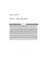
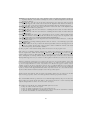
B TLA+ Specification
59
Bibliography
74
4
List of Figures
2.1
2.2
Barrelfish OS structure on a four core ARMv7-A system. . . . . . .
One dispatcher and three user-level threads, each with their associated
stacks and memory areas to store the register state when they are
not running. . . . . . . . . . . . . . . . . . . . . . . . . . . . . . . . .
12
13
3.1
3.2
3.3
Intel RTM Commit and Abort Scaling . . . . . . . . . . . . . . . . .
Intel RTM Commit and Abort Scaling with Barrier . . . . . . . . . .
Hyper-Threading and nop loop . . . . . . . . . . . . . . . . . . . . .
18
20
25
4.1
Alert handler register state . . . . . . . . . . . . . . . . . . . . . . .
30
Extended MOESI cache-coherency protocol with four new alert states:
AM, AO, AE, AS. . . . . . . . . . . . . . . . . . . . . . . . . . . . .
5.2 Layout of memory structure to support alerts . . . . . . . . . . . . .
5.3 Example two states that relate by the ThreadYield action. . . . . . .
38
41
44
6.1
6.2
48
51
5.1
Message latency breakdown. . . . . . . . . . . . . . . . . . . . . . . .
Application overhead for 1, 10 and 100 UMP channels . . . . . . . .
5
List of Tables
4.1
Alert-on-update ISA extension instructions. . . . . . . . . . . . . . .
30
5.1
Encoding of AOU instructions using co-processor 3 . . . . . . . . . .
37
6.1
6.2
Gem5 simulation parameters. . . . . . . . . . . . . . . . . . . . . . .
Benchmark results from compute-intensive task that also receives
UMP messages using 1 channel. . . . . . . . . . . . . . . . . . . . . .
47
6
49
List of Listings
2.1
3.1
3.2
4.1
4.2
4.3
4.4
Code pattern for Restricted Transactional Memory (RTM). . . . . .
Microbenchmark to measure base cost of setting up and committing
a transaction. An empty transaction is executed one million times.
The base cost of setting up and committing a transaction is computed
by dividing the total execution time by the number of iterations. . .
Microbenchmark to measure the time until a transaction containing
an infinite nop loop gets aborted. . . . . . . . . . . . . . . . . . . . .
Enable monitoring for waitset. . . . . . . . . . . . . . . . . . . . . .
Disable monitoring for waitset. . . . . . . . . . . . . . . . . . . . . .
Test whether waitset is monitored. . . . . . . . . . . . . . . . . . . .
Event dispatch function for a monitored waitset. . . . . . . . . . . .
7
11
17
20
33
34
34
34
Chapter 1
Introduction
Message passing, as a communication and synchronization mechanism, has gained
increased adoption. It is used as the only form of communication between processes
in Erlang [11, Chapter 5] and is an integral part of the Go programming language.
The user guide Effective Go postulates: “Do not communicate by sharing memory;
instead, share memory by communicating.” [21] Moreover, on large-scale clusters,
MPI [36], a portable message passing system, is the programming model of choice [41].
In the area of operating systems, favoring message passing over shared memory has
been an important design decision for the Barrelfish [13] operating system. And
in the Linux community, there is an ongoing effort to replace D-Bus with a more
efficient inter-process communication system [19].
In this thesis, we restrict ourselves to inter-core message passing within a cachecoherency domain. State-of-the-art message passing between two processes in such
a system bypasses the kernel altogether and relies on shared memory for message
transfer [14]. Note that while the implementation of the message passing facility
employs shared memory, it is different from a programming model where processes
or threads directly share an address space. With message passing, all communication
is explicit and the processes do not rely on shared memory, only on the message
passing mechanism. They do not need to be adapted if they were run on two cores
that do not share memory, as long as a form of message passing is available.
User-level message passing (UMP) of Barrelfish demonstrates that message passing
in such a system can provide high bandwidth. By exploiting knowledge of the
cache-coherency protocol, cache-line-sized messages can be transferred directly from
the sender’s cache to the receiver’s without going through main memory.
The receiver uses polling to detect the arrival of new messages. While a tight polling
loop on the receiver results in low-latency message delivery, it is wasteful and often
not feasible to poll for an extended amount of time because other computation
needs to be done.
8
What really is missing is an efficient way for the sender to notify the receiver that
there is a new message. This is the problem this thesis tackles. While notifications
can be sent by involving the kernel and using inter-processor interrupts, such a
notification scheme would be very heavy-weight compared to the size of the message.
Our goal is to provide a notification mechanism that is light-weight and works
completely in user space.
To arrive at our goal, we will incorporate ideas from hardware transactional memory.
In particular, hardware transactional memory systems like Intel’s Transactional
Synchronization Extensions (TSX) allow to monitor a set of cache lines and trigger
a control transfer if any of them changes. We will use such a mechanism as the
basis of our message notification scheme.
After introducing concepts and terminology used throughout this thesis in Chapter 2,
Chapter 3 will analyze to what extend Intel’s TSX can be used to accelerate message
passing. We will find that while the mechanisms provided by TSX would be useful
for message notification, it cannot, in its current form, be used for such a purpose.
Consequently, Chapter 4 describes a simple hardware mechanism, alert-on-update,
that carries over features from hardware transactional memory systems but has an
API suitable for message notification. The implementation of the alert-on-update
hardware extension in a CPU simulator as well as how we use this extension for
message passing in Barrelfish is presented in Chapter 5. Chapter 6 evaluates the
effectiveness of the hardware feature and the software implementation, whereas
Chapter 7 surveys related work. Finally, Chapter 8 concludes and gives directions
for future work.
Appendix A describes changes made to Barrelfish that are unrelated to message
passing but were nevertheless necessary to get a working system. Appendix B
contains a formal specification of our implementation in TLA+.
9
Chapter 2
Background
This chapter provides background information on two topics used throughout the
thesis. Section 2.1 introduces hardware transactional memory and in particular
Intel’s TSX while Section 2.2 gives an overview of the Barrelfish operating system.
2.1
Hardware Transactional Memory
Recently, several implementations of hardware transactional memory systems have
appeared. The processor used in the Blue Gene/Q supercomputer has hardware
support for transactional memory [25, Section 2.15] and the Power ISA Version
2.07 [26, Book II, Chapter 5] features it. Moreover Intel’s Haswell processors support
it [28, Chapter 15] and AMD proposed their own version of transactional memory [3].
In this section, we give a brief overview of Intel’s Transactional Synchronization
Extensions (TSX) in Section 2.1.1, and in Section 2.1.2 we describe how AMD’s
proposed Advanced Synchronization Facility (ASF) differs. The interested reader
will find a more in-depth discussion of hardware transactional memory systems,
both industry designs and research proposals, in Harris et al. [23, Chapter 5].
2.1.1
Intel Transactional Synchronization Extensions
Intel’s TSX [27, Chapter 12] [28, Chapter 15] [33] provides two separate programming
interfaces. The first, Hardware Lock Elision (HLE), is based on work by Rajwar
and Goodman [37] on speculative lock elision. The high-level idea of HLE is to
optimistically execute critical sections without taking the lock, thereby exploiting
dynamic parallelism, and fallback to acquiring the lock only if a conflict arises during
actual execution.
10
The interface consists of two new instruction prefixes xaquire and xrelease.
xaquire prefixes the assembly instruction that acquires the lock while xrelease
prefixes the corresponding lock release instruction. These prefixes are forward
compatible: older processors that do not support HLE simply ignore these two
prefixes, therefore always taking the fall back path of acquiring the lock.
The second interface is called Restricted Transactional Memory (RTM) and allows
to execute an instruction sequence transactionally. Unlike HLE, this interface is not
forward compatible, it generates an exception if used on an unsupported CPU.
Listing 2.1 shows the common code pattern used with RTM. Transactional execution
is started with the xbegin instruction. It takes as single argument the address of the
fallback path in case the transaction aborts. xend marks the end of the transactional
region. If there are no conflicts, xend commits all changes to memory atomically.
Otherwise, the transaction aborts, any updates to memory since the start of the
transaction are discarded, and execution continues at the fallback address.
xbegin abort
# executed transactionally
xend
jmp continue
abort:
# fallback path
continue:
Listing 2.1: Code pattern for Restricted Transactional Memory (RTM).
In order to detect conflicting accesses between a transaction executing on one
processor and all other processors, the hardware tracks the read- and write-set for
each transaction. As the names imply, the read-set contains all memory locations the
transaction read while the write-set contains all locations written. A data conflict
occurs if another processor reads from a memory location in the write-set of the
transaction or writes to a location in the read- or write-set of the transaction.
Data conflicts are a primary reason of aborts. Transactions also abort if they
contain one of the many unsupported instructions, examples include the pause
instructions, ring transitions (sysenter, syscall), legacy I/O operations (in, out),
monitor and mwait, etc. [28, Section 15.3.8]. There are many more reasons why a
transaction might abort, like limited architectural resources to buffer the changes
made by an uncommitted transaction or interrupts happening during transactional
execution [27, Section 12.2.3]. Transactions can also be explicitly aborted using the
xabort instruction.
If a transaction aborts, all changes made to memory and registers are discarded and
execution continues at the fallback address. The eax register contains information
about the abort, why it happened and whether a retry might succeed. All other
registers contain the value they had at the time the transaction was started with
xbegin.
11
2.1.2
AMD Advanced Synchronization Facility
AMD’s ASF [3] is similar to Intel’s TSX except for two major differences. First,
it allows for loads and stores to bypass the transactional mechanism. With TSX,
all loads and stores within a transaction are implicitly transactional. ASF allows
loads to optionally not be added to the read-set and for stores to optionally take
immediate effect. Both types of loads and stores can occur within a transaction and
they are distinguished by whether or not the x86 mov instruction carries the lock
prefix.
Second, the register state is not automatically checkpointed when the transaction
starts and restored when an abort is triggered. Instead, software is responsible for
saving and restoring them. As a result, the registers at the time execution was
interrupted by the abort are available to the abort handler except, for rax, rip,
rsp and rflags, which are overwritten.
2.2
2.2.1
Barrelfish Operating System
Overview
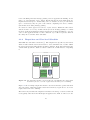
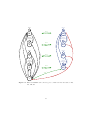
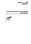
Barrelfish is a research operating system developed by ETH Zurich. It is structured
as a multikernel [13] and a high-level overview of the system architecture is depicted
in Figure 2.1.
User space
Kernel space
Hardware
Domain 3
Domain 1
Domain 2
Dispatcher
Dispatcher
Dispatcher
Dispatcher
Monitor
Monitor
Monitor
Monitor
CPU
Driver
CPU
Driver
CPU
Driver
CPU
Driver
ARMv7-A
core
ARMv7-A
core
ARMv7-A
core
ARMv7-A
core
Figure 2.1: Barrelfish OS structure on a four core ARMv7-A system.
The figure shows a four core ARMv7-A CPU running Barrelfish. Each core runs
its own copy of the kernel, called CPU driver, and they do not share any state.
Like in a microkernel, the CPU driver is only responsible for enforcing protection,
12
basic scheduling and fast message passing between applications running on the
same core. In particular, device drivers, filesystems and the networking stack are
implemented in user space. Additionally, each core runs the monitor process in user
space. Collectively, they are part of the trusted computing base and coordinate
system-wide state using message passing.
Processes are called application domains or just domains. While the CPU driver
and the monitor do not rely on shared memory but use message passing for communication, applications might use shared address spaces and span multiple cores. For
each core the application runs on, there exists an object called dispatcher, which is
the entity the local CPU driver schedules.
2.2.2
Dispatchers and User-level Scheduler
Barrelfish uses scheduler activations [5]. The dispatcher is upcalled by the kernel,
which, in turn, runs the user-level scheduler to decide which thread to resume. While
the user-level scheduler runs, further upcalls are disabled. If the kernel interrupts the
domain while upcalls are disabled, it later resumes the domain instead of upcalling
it.
Domain
Thread 1
Thread 2
Thread 3
stack
stack
stack
register
save area
register
save area
register
save area
Dispatcher
enabled
save area
stack
disabled
save area
disabled
flag
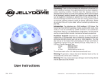
Figure 2.2: One dispatcher and three user-level threads, each with their associated stacks
and memory areas to store the register state when they are not running.
Figure 2.2 shows a single dispatcher and three user-level threads together with their
associated state. Each thread has a stack and a memory region used to store the
register state if it is not running.
The kernel only schedules the dispatcher and has no knowledge of user-level threads.
Consequently, when the kernel interrupts an application domain, it cannot store the
13
register state directly to the thread save area. Instead, the register state is stored in
the enabled or disabled area of the dispatcher, depending on whether upcalls were
enabled or disabled at the time the interrupt happened. If upcalls were disabled,
the kernel later resumes the dispatcher with the register state from the disabled
area. If they were enabled, the dispatcher is upcalled and starts executing on its
own stack. It has knowledge of the user-level threads and knows which one was last
run and can copy the register state from the enabled area to the save area of the
corresponding thread before scheduling another thread.
2.2.3
User-level Message Passing (UMP)
For inter-core communication, Barrelfish uses a variant of URPC [14]: a shared
memory region is used as communication channel between one sender and a single
receiver. After a setup phase, all communication happens completely in user space
without any kernel involvement. Thus, it is appropriately named user-level message
passing (UMP).
The shared memory region is organized into cache-line-sized messages. Sending a
message simply consists of writing it to the shared region while the receiver uses
polling to detect a new message.
UMP provides a high bandwidth messaging channel. On a system with a MOESI
cache coherency protocol the message is directly transferred from the sender’s cache
to the receiver’s without going through main memory. In the common case, only two
bus transactions are necessary: one when the sender starts writing and invalidates
the cache line on the receiver’s side and one when the sender polls. When the latter
happens, the modified cache line transitions to the Owned state on the sender and
the receiver cache fetches it there [13].
UMP communication can be low latency but only if the receiver continuously polls.
Otherwise, the latency is directly correlated to the polling frequency.
2.2.4
Flounder
Apart from UMP, Barrelfish provides other means of message passing, for example
local message passing (LMP) between domains running on the same core.
On top of these low-level and fixed-message-sized communication channels, Barrelfish
features a higher-level messaging infrastructure called Flounder [12] which provides
a common interface regardless of the type of message passing used. Additionally, it
handles marshalling and demarshalling between application messages and fixed-sized
interconnect messages.
The runtime support for message passing comes in the form of waitsets. A waitset
bundles multiple channel endpoints and presents activity on the channel, for example
an newly arrived message, as events. Internally, the waitset categorizes the channels
14
into three groups: pending, polled and idle. Channels in the pending group have at
least one pending event that is ready to be handled, whereas channels in the idle
group have none. For channels in the polled group, we do not know whether or not
there is a pending message and need to poll them regularly.
A UMP channel is part of either the polled or the pending group of a waitset. If we
already know that there is a pending message, it is in the pending list, otherwise it
is in the polled list.
To handle events, the function event_dispatch is called on a waitset, commonly
inside an infinite loop. On each invocation, the following steps are performed. First,
it is checked whether there are channels in the pending group. If there are, the next
event from one of them is handled. If there are no pending channels, it is checked
whether any of the channels in the polled queue has an event. If that is the case,
the event is handled, otherwise, the function blocks.
15
Chapter 3
Using Intel TSX to
Accelerate Message Passing
In this chapter, we analyze to what extent Intel TSX can be used to accelerate
message passing. Section 3.1 evaluates the performance characteristics of TSX. In
Section 3.2 we describe our initial idea of using the control transfer triggered by an
abort as a notification mechanism for message passing and identify why the TSX
abort handler cannot be used for notification. The two sections that follow, describe
alternative ways how TSX might be employed to accelerate message passing.
3.1
RTM Performance Analysis
In this section we analyze the performance of TSX and in particular RTM by a series
of microbenchmarks. All measurements were done on an Intel Core i7-4770 running
at 3.40GHz. Frequency scaling was effectively disabled by setting the minimum
and maximum frequency to 3.40GHz. For the benchmark, Hyper-Threading was
disabled in the BIOS and Turbo Boost was turned off by setting the value in
/sys/devices/system/cpu/intel_pstate/no_turbo to 1. The system software
consisted of Linux kernel 3.14.2, glibc 2.19 and gcc 4.9. All benchmarks use a single
thread which was pinned to a specific processor core and the rdtscp instruction was
used to measure execution time.
The microbenchmarks answer the following questions:
• What is the overhead of setting up and committing a transaction? (Section 3.1.1)
• What is the overhead of aborting a transaction? (Section 3.1.2)
16
• How does the cost of setting up, committing and aborting a transaction scale
with increased transaction size? (Section 3.1.3)
• Is there a time limit for transactional execution? (Section 3.1.4)
3.1.1
Setup and Commit Overhead
The first microbenchmark measures the base cost of setting up and committing a
transaction by measuring the execution time of an empty transaction. Listing 3.1
shows the code used for the microbenchmark. To amortize the cost of reading the
time stamp counter, the execution time for multiple transactions (one million in
our case) is measured and the total execution time is divided by the number of
transactions executed to arrive at the base cost of setting up and committing a
single transaction. Because the transactional memory intrinsics (_xbegin(), _xend()
and _xabort()) for gcc result in a suboptimal code pattern, inline assembly was
used instead.
1
2
3
4
5
6
7
// read time stamp counter
for (int i = 0; i < 1000000; i++) {
__asm__ __volatile__("xbegin 1f
"xend
"1:");
}
// read time stamp counter
\n\t"
\n\t"
Listing 3.1: Microbenchmark to measure base cost of setting up and committing a
transaction. An empty transaction is executed one million times. The base
cost of setting up and committing a transaction is computed by dividing the
total execution time by the number of iterations.
The above described microbenchmark was run ten times. The average overhead of
setting up and committing a transaction was 47.89 cycles with a standard deviation
of 0.06 cycles.
3.1.2
Abort Overhead
The next benchmark measures the overhead of aborting a transaction. To this end,
we measure the execution time of a transaction that contains as its only instruction
an explicit abort. The only difference between this benchmark and the one shown
in Listing 3.1 is that between lines 3 and 4 an explicit xabort 0xff is inserted.
The benchmark was again run ten times resulting in an average time of 155.22
cycles to setup and abort a transaction, with a standard deviation of 0.29 cycles.
We assume that the abort is significantly slower than the commit because on an
abort, the register state from the time the transaction started must be restored and
there is a control transfer to the address of the abort handler.
17
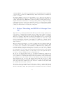
3.1.3
Setup, Commit and Abort Overhead Scaling
Having investigated the execution time of an empty transaction as well as the
cost of immediately aborting a transaction, this section looks into the overhead of
committing or aborting a transaction of increasing size and compares it to executing
the same instruction sequence non-transactionally.
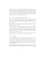
The benchmark explores transaction sizes, measured in number of cache lines
modified, between 0 and 100. A transaction of size x writes a 64 bit magic number
to the first cache line, then writes the same 64 bit magic number to the neighboring
cache line and so on, until x cache lines are modified. Since the same magic number
is written to all cache lines, there is no dependency between the writes.
The execution time of each transaction is timed individually and the cache is
cleared between measurements. For each size and each mode (non-transactional,
transactional commit, transactional abort) 10’000 measurements are averaged. The
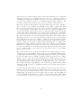
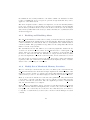
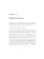
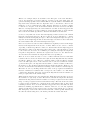
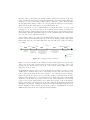
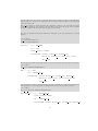
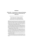
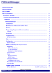
resulting graph is depicted in Figure 3.1.
Transactional Commit and Abort Scaling (cold cache)
3000
non-transactional
transactional commit
transactional abort
Latency [cycles]
2500
2000
1500
1000
500
0
0
20
40
60
80
100
Number of cache lines written
Figure 3.1: Execution times for modifying an increasing number of adjacent cache lines
in three different scenarios. The first performs the modification outside of a
transaction (non-transactional), the second within a transaction that commits
(transactional commit) and the third within a transaction that explicitly
aborts after all modifications have been done (transactional abort).
The figure shows that in case the cache lines are modified within a committing
transaction, the execution time increases linearly with the size of the transaction.
In the non-transactional and transactional abort case, the execution time is nearly
constant for transaction sizes between 0 and 49 cache lines, followed by a sharp rise.
Afterwards, the execution time increases linearly with the size of the transaction.
18
Since the slope for transactions larger that 50 cache lines is the same for a committing
transaction and for the non-transactional case, there is a constant overhead of
committing a transaction. Likewise, the slope for an aborting transaction and
execution of the instruction sequence non-transactional is the same. Therefore, the
execution overhead of aborting does not depend on the size of the transaction.
The near constant execution time for the non-transactional case can be explained
due to the effect of store buffers. In a nutshell, a store buffer is a small cache that
sits between the CPU and its associated cache and holds outstanding writes until
the corresponding cache lines arrive [35] [27, Section 2.1]. In the benchmark, we
read the time stamp counter, write a series of cache lines and read the time stamp
counter again. The modifications to the cache lines are kept in the store buffer until
the cache lines arrive from main memory, which takes some hundred cycles due to
the cache being cleared before the measurement. Reading the time stamp counter
with rdtscp, however, does only wait until the modifications are recorded in the
store buffer and not for the store buffer to completely drain. For transaction sizes
smaller than 49 cache lines, the modifications fit in the store buffer which results in
a near constant execution time. Larger transactions fill up the store buffer, then
stall after each write, waiting for an entry in the store buffer to become available.
Haswell’s store buffer has 42 entries [27, Section 2.1.4.1]. The sharp increase in
execution time happens at 49 modified cache lines. The latter is larger since while
the store buffer is filled, some entries are already written back to cache making
space for more entries.
The execution time in case we abort the transaction has a similar shape and can be
explained by the same argument. However, in case we commit the transaction the
execution time increases linearly even for small transactions, which can be explained
by the way transactions are committed. During commit, at the latest, data conflicts
must be detected. Since the current implementation of TSX tracks the read- and
write-sets used for data conflict detection in the first-level cache [27, Section 12.1.1],
all outstanding entries in the load and store buffer must arrive in the cache before
the commit can happen. The draining of the load and store buffer during commit
causes the execution time for a committing transaction to increase linearly regardless
of transaction size.
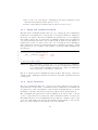
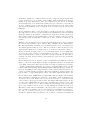
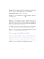
To verify our hypothesis that the near constant execution time is due to the store
buffer, we repeated the previous experiment but forced a drain of the load and
store buffer before reading the time stamp counter the second time in the nontransactional case as well as before the xabort in the aborting case. The drain was
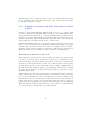
forced by using the mfence instruction. Figure 3.2 depicts the resulting graph, which
clearly shows that for all three scenarios there is a linear increase in execution time.
19
Transactional Commit and Abort Scaling (cold cache)
non-transactional with barrier
transactional commit
transactional abort with barrier
3000
Latency [cycles]
2500
2000
1500
1000
500
0
0
20
40
60
80
100
Number of cache lines written
Figure 3.2: Same experiment as in Figure 3.1, except that the load- and store buffers
are explicitly drained in the non-transactional and aborting transaction case.
3.1.4
Time Limit
In this last microbenchmark, shown in Listing 3.2, we investigate whether or not
there is a time limit for transactional execution. The benchmark starts by reading
the time stamp counter and entering transactional execution. The body of the
transaction contains an infinite nop loop, therefore the end of the transaction (xend) is
never reached. Instead, the execution is trapped in the nop loop until the transaction
gets aborted, at which point the time stamp counter is read again and the execution
time is computed.
for (int i = 0; i < 1000000; i++) {
// read time stamp counter
__asm__ __volatile__ ("xbegin 2f
"1:
"nop
"jmp 1b
"xend
"2:");
// read time stamp counter
// compute and store execution time
}
\n\t"
\n\t"
\n\t"
\n\t"
\n\t"
Listing 3.2: Microbenchmark to measure the time until a transaction containing an
infinite nop loop gets aborted.
Taking one million samples, the average execution time before the transaction
got aborted was 3.16 ms (10’752’920 cycles) with a standard deviation of 0.74 ms
20
(2’499’796 cycles). Since the average execution time lies in the range of the timer
interrupts of the Linux kernel, we conclude that there is no time limit and the
transactions in our experiment only get aborted due to timer and other kinds of
interrupts.
To conclude the performance analysis, we answer the questions posed at the beginning
of the section. The overhead of setting up and committing a RTM transaction
is 48 cycles, whereas the overhead of setting up and aborting is 155 cycles. Both
overheads are constant and do not depend on the size of the transaction. Moreover,
there is no time limit for a transaction.
Our results match the findings by Ritson and Barnes [38] in a similar performance
study of RTM. They also compared using a transaction instead of multiple compareand-swap instructions and found that using a transaction that modified two words
has the same performance as using two compare-and-swap instructions. If only one
word is modified, compare-and-swap is faster whereas transactions are faster if more
than two words are modified.
3.2
Abort Handler for Message Notification
RTM provides the means to detect when a set of cache lines get modified and allows
execution to continue at a predefined address in such an event. In this section,
we will argue why such a mechanism is useful not only for hardware transactional
memory but also for user-level notification and message passing.
At a high-level, user-level message passing between two cores, for example as
implemented in the Barrelfish operating system [31] [12], employs a shared memory
region for communication. One of the cores writes to the shared location whereas
the other regularly polls for new messages. Polling, however, is wasteful, especially
if low-latency message delivery is required and therefore a short polling interval
is used. A much better alternative would be for the sending core to inform the
receiving end that a new message is ready. Ideally, sending such a notification would
be done entirely in user space without going through the kernel, because traversing
the user-kernel boundary twice incurs a significant overhead.
Such a user-level notification and interrupt mechanism, in which a user-level process
running on one core sends a notification to a process running on another core, which,
in turn, transfers control to a notification handler and once finished continues where
it left of, is currently not implementable without going through the kernel. However,
the mechanism provided by RTM of detecting modifications of cache lines and
triggering a control transfer almost allows for user-level notifications. Subsequently,
we will describe how user-level notification could almost be implemented with RTM
and then describe what is lacking to make it actually work.
To illustrate how user-level notification could almost be implemented, let us assume
that a thread running on core 0 wants to notify a thread running on core 1. A memory
21
region shared between both threads is used for communicating the notification and
sending the notification simply consists of writing a value, for example 1, to the
shared memory region. The novelty lies in the way the notification is received.
Instead of polling the shared memory location regularly, the receiver registers a
notification handler during initialization which is invoked when a notification is
received. Registering the notification handler involves starting a transaction with
xbegin handler, where handler is the address of the user-level notification handler.
Then it transactionally reads the shared memory location, thereby adding it to
the read-set of the transaction. Without completing the transaction with xend,
execution continues as normal. All memory operations, except the initial reading
of the shared memory location, are done non-transactional, i.e. although they are
within a transaction, they are not added to the read- or write-set of the transaction
and therefore not used for conflict detection and not rolled-back during an abort.
Once core 0 sends the notification by writing 1 to the shared memory location,
core 1 aborts the transaction because a cache line in the transactions read-set was
modified, and execution continues at the specified handler address. The notification
handler processes the notification, re-registers the notification handler, restores the
execution context before it was interrupted and jumps back to the point where it
left off before receiving the notification.
The above described approach for user-level notification can also be applied to userlevel message passing where the sender, instead of writing just the value 1, writes
the actual message to the shared memory buffer. The receiver gets notified without
polling that a message arrived and can handle the message right away or record that
a message arrived. This approach is not limited to a single message channel. The
receiver can monitor any number of channels by adding the corresponding memory
location to its read-set during setup. This provides a powerful mechanism to wait
for a message on any number of channels without actually having to poll.
While RTM features a mechanism to detect changes in any number of cache-lines,
the above described approach does not work with RTM for several reasons. First,
our approach requires that once the notification or message handler is registered,
transactional execution continues but references and modifications to memory
locations are non-transactional. Intel TSX does not provide such a feature. All
memory references between xbegin and xend are implicitly transactional and all
references outside of a transaction are non-transactional. There are, however,
hardware transactional memory systems that support such a feature, for example
AMD’s proposed Advanced Synchronization Facility [3].
Second, if a RTM transaction gets aborted, the execution context, e.g. register content, is not retained. Instead, the register state at the point the transaction started
is restored. Since the execution context where normal execution was interrupted
is not available in the notification handler, there is not way to continue execution
there. The only state which is available is the instruction pointer at which the
transaction got aborted. It is not available by default but can be made available by
enabling Precise Event Based Sampling (PEBS) [30, Section 18.11.5.1]. However,
22
enabling PEBS is only possible from ring 0 and the mechanism incurs a significant
overhead: the abort induces a PEBS interrupt, which in turn writes the instruction
pointer to a buffer.
In summary, RTM provides the basic mechanism to detect changes in any number of
cache lines and allows execution to continue at a specified address. Nevertheless, the
current implementation of RTM has several shortcomings rendering it impossible to
implement user-level notification or message passing without polling in a straightforward way. Next, we explore two alternative ways to accelerate message passing
using TSX. These two alternatives do not try to employ notifications in lieu of
polling but instead aim at reducing the polling time.
3.3
Helper Threading and RTM for Message Passing
Applications in operating systems like Barrelfish [13] that use message passing as the
basic means of communications quickly end up polling a large number of message
channels, where polling latency increases linearly with the number of channels.
Instead of replacing polling with a notification mechanism as proposed in the last
section, an alternative way to accelerate message passing is to reduce the polling
latency from linearly dependent on the number of channels to constant. Such a
decrease in polling time can be achieved using a concept commonly referred to as
helper threading.
The idea of helper threading is to accelerate a primary thread by using an additional
execution context (also called logical core, hyperthread or hardware thread ). This
is often used in combination with Simultaneous Multithreading (SMT) where
both the primary and helper thread run on the same core but on two different
hardware threads. Helper threading has been used previously for speculative
precomputation [18] [43], where the helper thread prefetches data for the primary
thread thereby reducing the number of cache misses on the critical path. It has also
be used to overlap communication and computation [22].
In our case, the helper thread is used to poll all the channels the application is
interested in and summarizes the readiness in a single word. In a simple scheme, this
word contains a boolean flag indicating whether any channel is ready. Alternatively,
the summary word could contain one bit for each channel polled, precisely indicating
which channels, if any, are ready. The primary thread still polls, but before polling
all the different channels, it checks the summary word to see if any channel is ready
and only polls if some channels are ready. In case no channel is ready, this results
in constant instead of linear overhead.
The helper thread performs the following steps. First, it starts transactional
execution with xbegin handler. Then it reads all the message channels the primary
thread is currently polling. The primary thread communicates the list of message
23
channels by writing it to a shared memory location. Next, the helper thread waits
for the transaction to abort while doing nothing. This is implemented with an
infinite loop of nop instructions. Once the transaction aborts, the abort handler
checks whether any of the channels is actually ready (it could have been a spurious
abort for example because a cache line from the read-set was evicted from the cache)
and writes the summary word accordingly. Now, the same steps are repeated ad
infinitum.
As an optimization and to reduce the number of spurious aborts due to interrupts,
the helper thread could be executed in ring 0 as a minimal helper kernel with all
interrupts disabled. Depending on whether the application would benefit from
such a helper kernel, it could dynamically be enabled or disabled. Recent research
demonstrated that dynamically booting new or other versions of kernels [45] is
feasible.
Whether or not the helper kernel accelerates the main application depends on whether
the increase in performance due to faster polling outweighs the two disadvantages.
The first disadvantage is having only one hardware thread per core available for
the main application instead of two. The second is the possible slowdown of the
application resulting from executing a nop loop on the second hardware thread.
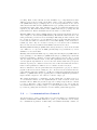
We expected that executing a nop loop on one hardware thread does not significantly
slow down the other execution context running on the same core, and performed a
series of measurement to verify or invalidate our hypothesis. Except when stated
otherwise, the same system, software, and settings were used as for the experiments
in Section 3.1.
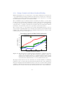
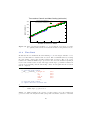
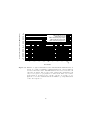
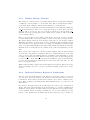
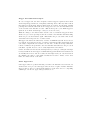
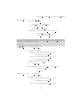
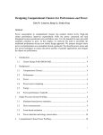
The measurements were performed on nine benchmarks in six different scenarios,
Figure 3.3 shows the result. Eight of the nine benchmarks, namely block tri-diagonal
solver (BT), scalar penta-diagonal solver (SP), lower-upper gauss-seidel solver (LU),
conjugate gradient (CG), multi-grid on a sequence of meshes (MG), discrete 3d fast
fourier transformation (FT), embarrassingly parallel (EP) and integer sort (IS), are
from the OpenMP reference implementation of the NAS Parallel Benchmarks [2]
version 3.3.1 with class B problem size. The last benchmark (compile) measures the
time it takes to compile Linux kernel version 3.14.2 using eight threads (make -j8).
For the first scenario (SMT-disabled), Hyper-Threading was disabled in the BIOS.
The benchmarks could make use of all four cores available on the i7-4770 with one
execution context each. This scenario serves as the base line for comparison with
other scenarios. All except the first scenario have Hyper-Threading enabled. In the
second scenario (SMP-enabled-notused), the benchmarks were restricted to use only
one execution context per core. Since nothing else was running on the test system,
the second execution context of each core was running the Linux kernel idle loop.
The third scenario allows benchmarks to use all execution contexts. The remaining
three scenarios are similar to the second in that the benchmarks are restricted to
use only one execution context per core. In all three scenarios, four additional
threads are spawned which are pinned to the execution contexts the benchmark is
24
execution time relative to baseline (SMP-disabled)
2
1.9
1.8
1.7
1.6
1.5
1.4
1.3
1.2
1.1
1
0.9
0.8
0.7
0.6
0.5
0.4
0.3
0.2
0.1
0
SMT-disabled
SMT-enabled-notused
SMT-enabled-used
SMT-enabled-noploop-simple
SMT-enabled-noploop-multi
SMT-enabled-noploop-pause
le
pi
m
co
IS
EP
G
FT
M
G
C
LU
SP
BT
Benchmarks
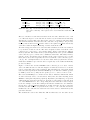
Figure 3.3: Runtime of eight benchmarks from the NAS Parallel Benchmarks suite as
well as one compile benchmark (compiling Linux kernel 3.14.2) in different
scenarios. The first scenario has SMT disabled and serves as base line, all
other have it enabled. The second scenario restricts the benchmark to run
only on one logical core per physical core whereas the third does not have
such restriction. Scenarios four to six also only use one logical core per
physical core for the benchmark and run an infinite loop of nop instructions
on the other logical core.
25
not using. Each of these threads executes an infinite loop of nop instructions. The
difference between those scenarios is the kind of nop loop they are running. Scenario
four (SMT-enabled-noploop-simple) uses a one byte nop instruction encoded as
0x90 whereas the fifth scenario (SMT-enabled-noploop-multi), uses the multi-byte
nop instruction 0x0f 0x1f 0x00, which is one of the recommended multi-byte nop
sequences [29]. The sixth and last scenario (SMT-enabled-noploop-pause) uses the
pause instruction. Each benchmark was ran ten times for each scenario.
Enabling SMT but not using it (SMT-enabled-notused) incurs a median slowdown of
4.3% compared to the base line (SMT-disabled). We attribute this slowdown to the
static partitioning of CPU resources when Hyper-Threading is enabled. Each of the
two execution contexts per core gets half the resources of any statically partitioned
resource like the number of entries in the reorder buffer (ROB) or the load and store
buffers [42]. Since only one execution context per core is used for the benchmark,
there are less resources available when SMT is enabled but not used.
Enabling SMT and using it (SMT-enabled-used) is faster by 9.5% in the median
case. This is to be expected as SMT generally improves performance by better
utilization of execution units.
Running a thread with an infinite nop loop using either the single byte (SMT-enablednoploop-simple) or the multi-byte (SMT-enabled-noploop-multi) nop version has
identical performance. Relative execution time ranges between a factor of 1.06
and 1.55 with a median slowdown of 22%. The significant slowdown suggests that
even though the nop instruction does not alter the architectural state (except the
instruction pointer), it consumes execution resources. The x86 architecture therefore
lacks a real nop instruction which does not consume execution resources.
Intel recommends to use the pause instruction in spin-wait loops [29]. It “will depipeline a thread’s execution, causing it to not contend for resources such as the trace
cache until the pause has committed.” [42] However, using the pause instruction in an
infinite loop (SMT-enabled-noploop-pause) did not result in significant performance
improvements compared to the other two versions of nop loops.
The results from Figure 3.3 invalidate our hypothesis that executing a nop loop
on one hardware thread does not significantly slow down execution on the other
hardware thread. While the presented approach of using a helper thread or kernel
to reduce polling time could be implemented with TSX, we do not expect that the
slowdown incurred by executing a nop loop on the hyperthread can be compensated
by a reduced polling time and therefore did not further pursue this approach.
3.4
n : 1 communication channels
Yet another way to reduce polling time is to lower the number of communication
channels. In Barrelfish, UMP channels are point-to-point channels between exactly
two communication partners. Additionally, each channel internally consists of a
26
memory region for sending and receiving respectively. This has the benefit that no
synchronization is needed for the sender. On the downside, essential OS domains
like the monitor end up having to poll a large number of channels.
Using n : 1 channels with multiple senders and one receiver would drastically reduce
the number of channels and therefore the time spent polling. For synchronization
between the senders TSX could be used. Depending on the implementation of the
messaging channel, though, a single compare-and-swap would be all that is needed to
synchronize the senders. As mentioned in Section 3.1 Ritson and Barnes [38] found
that using a single compare-and-swap instruction is faster that using a transaction.
Therefore, CAS is a better fit as synchronization primitive for n : 1 communication
channels.
3.5
Conclusion
In this chapter, we learned that the abort mechanism of TSX provides a low-overhead
control transfer. However, the current incarnation of TSX is not flexible enough
such that it can be repurposed and used for user-level notification. We explored two
alternative ways to accelerate message passing using TSX by reducing the polling
time. The first approach relied on helper treading but did not yield the expected
performance, while the second approach of using n : 1 channels can be better solved
by using compare-and-swap instructions instead of transactions.
We conclude that TSX, in its current form, cannot be used to accelerate message
passing.
27
Chapter 4
Using Alert-on-Update to
Accelerate Message Passing
In the last chapter we found that TSX cannot be used to accelerate message passing.
In the first part of this chapter (Section 4.1) we will propose and describe a simple
ISA extension alert-on-update (AOU) that allows a programmer to register an alert
handler which is invoked by hardware whenever any element in a set of memory
locations changes. Such a feature has been proposed before [40] but with a different
API and it has only been studied in the context of software transactional memory [39]
whereas we use it for message passing.
The middle part of the chapter (Section 4.2) gives a high-level overview how the alerton-update hardware feature can be used to accelerate user-level message passing by
removing the need for constant polling using Barrelfish’s user-level message passing
(UMP) as a running example.
In the last part (Section 4.3), we describe how AOU fits into the larger message
passing framework of the Barrelfish operating system. We present the API provided
to the application programmer that allows to use alerts instead of polling for specific
domains and waitsets. Details as to how this API is implemented, will be given in
the next chapter. Barrelfish was chosen as the operating system to experiment with
AOU because it already features a comprehensive message passing framework.
4.1
Alert-on-Update ISA Extension
This section presents the alert-on-update ISA extension. We decided to use ARMv7A as the base ISA since it is a widely used instruction set, yet still much simpler
than x86. Also, CPU simulators as well as operating systems running on top of
28
the simulators were readily available to the author. While our discussion of AOU
focuses on ARMv7-A, most concepts are general enough such that they can be
applied to other ISAs as well.
The alert-on-update feature consists, at a high-level, of four new assembly instructions, a set of memory locations that are monitored by hardware, an alert handler
that is called by hardware whenever any of the monitored memory locations changes,
and a memory buffer that is allocated by software and written to by hardware when
an alert is triggered.
4.1.1
Enabling and Disabling Alerts
The aou start instruction enables the receiving of alerts and takes two arguments.
The first argument is the virtual address of the alert handler. When an alert happens,
control is transferred to this address. The second argument is the virtual address of
a memory buffer. The programmer is responsible for allocating this buffer and it
must be at least 8 bytes in size.
The dual instruction aou end, which does not take any arguments, disables the use
of alerts. No alerts are received after an aou end and before a subsequent aou
start. Moreover, the instruction clears the set of memory locations that were
monitored. After an aou end, the hardware no longer uses the memory buffer
provided as argument to the most recent aou start, and it can therefore be freed.
For each execution context provided by the CPU, alerts can be enabled and disabled
separately. The aou start and aou end instructions implicitly enable or disable
alerts for the context they are executed in.
4.1.2
Modify Set of Monitored Memory Locations
The set of memory locations monitored can be modified by the aou monitor and
aou release instructions. Both take as single argument the virtual address of the
memory location to monitor or release respectively. The instruction aou monitor
adds a memory location to the initial empty set whereas aou release removes it.
Memory locations are handled at cache line size granularity. Any address that
corresponds to a specific cache line can be used to add the corresponding cache line
to the set of monitored cache lines. Also, the argument provided to aou monitor
and aou release must not be aligned.
Each execution context has its own set of monitored cache lines and the aou monitor
and aou release instructions implicitly add or remove the cache line to the set
belonging to the context they are executed in. Note that these sets do not have to
be disjoint, a certain memory location can be monitored from multiple execution
contexts.
29
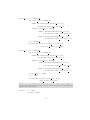
aou
aou
aou
aou
start
monitor
release
end
<alert handler> <buffer address>
<address>
<address>
Table 4.1: Alert-on-update ISA extension instructions.
Table 4.1 summarizes the four instructions that make up the alert-on-update ISA
extension.
4.1.3
Alert
If any line from the set of monitored cache lines is modified by an execution context
other than the current one, an alert for the current context is triggered and the
following steps are performed in hardware. The current value of the r1 register
is written to the memory buffer at offset 0. Likewise, the current value of the pc
register is written to the buffer at offset 4. Next, the virtual address of the memory
buffer is stored in the r1 register and the address of the alert handler is stored
in the pc register causing execution to continue at the alert handler. While an
alert is triggered, further alerts are disabled and the set of monitored cache lines is
cleared as if an explicit aou end was called. Therefore, the alert handler must not
be reentrant.
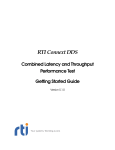
r1
old r1
offset 0
old pc
offset 4
Figure 4.1: Alert handler register state: the r1 register points to the memory buffer
containing the old values of the r1 and pc registers.
Figure 4.1 depicts the state before the first instruction of the alert handler is executed.
The r1 register points to the memory buffer containing the old values of the r1
and pc register from the time normal execution was interrupted by the alert. All
registers except r1 and pc still contain the values from normal execution. It is at
the programmers discretion to save and restore the registers trashed by the alert
handler.
4.1.4
Implicit Disabling of Alerts
As mentioned before, alerts get implicitly disabled when an alert is triggered. There
are, however, two other important cases that cause alerts to get disabled.
Firstly, alerts get implicitly disabled by any change in privilege level. For example,
if the privilege level changes from PL0 (user mode) to PL1 (FIQ, IRQ, supervisor,
30
etc.), alerts get disabled. This entails that they get disabled when running in user
mode and an interrupt happens or a supervisor call is made. If alerts were not
implicitly disabled by a change in privilege level, an alert handler that was setup in
user mode but triggered while at PL1 would have elevated access rights.
Secondly, alerts get disabled by any change in the TLB or cache configuration. This
includes all instructions that operate on co-processor 15.
An implicit disabling of alerts has the same effect as an explicit aou end, i.e. no
alerts are received afterwards until the next aou start and the set of monitored
cache lines is cleared.
4.1.5
Spurious Alerts
In the usual case, an alert is triggered if alerts are enabled and a cache line gets
modified by a context other than the current one after it has been added to the
set of monitored cache lines but before alerts were explicitly or implicitly disabled.
However, for implementation dependent reasons, a spurious alert might happen
anytime alerts are enabled. A spurious alert is any alert that is not triggered as the
result of a modification of a monitored cache line.
The semantic for when an alert is triggered is that whenever alerts are enabled,
a modification of a monitored cache line always triggers an alert. However, the
opposite is not true. An alert does not imply that a cache line was modified.
The hardware does not give any indication whether a particular alert was a spurious
alert or not. It is the responsibility of the programmer using application specific
knowledge to check whether actually something changed.
4.2
Message Passing Without Polling
Now that we have an understanding of how the alert-on-update feature works, let
us discuss how AOU can be employed to accelerate message passing. We will use
Barrelfish’s UMP message passing as an example to guide the discussion.
The goal is to reduce the number of times polling is necessary and in many cases
getting rid of polling altogether by using alerts. This can be achieved in several
different ways. The most straight-forward way, presented in Section 4.2.1, directly
monitors the cache line the next message will be received in. Alternatively, one can
make use of a dedicated memory region for notification (Section 4.2.2).
31
4.2.1
Monitor Message Channel
The setting we consider is that of a sending thread and a receiving thread running
on different cores in parallel, i.e. at the same time. The receiving thread wants to
get notified when a message arrives without having to poll all the time.
To this end, the receiving thread enables alerts whenever it is scheduled using the
aou start instruction. Moreover, it adds the memory location where the next
message will be received to the set of monitored memory locations using aou
monitor. Next, the receiving thread can continue its processing—it will get notified
once a message arrives.
The process of sending does not change at all. In fact, the sender does not even have
to know whether the receiver uses polling or relies on the alert-on-update feature.
The sender simply writes the next message (cache line) to the message channel.
This write will trigger an alert in the receiver, notifying it that a message arrived
and allowing it to act appropriately, for example, by handling the message right
away or by unblocking a high-priority thread that will shortly handle the message.
Afterwards, the receiving thread can continue at the point it was interrupted by the
alert.
The receiver is not restricted to monitor a single channel. After it enabled alerts,
it can monitor any number of channels. Moreover, channels that were torn down
can be removed and new channels that are established can dynamically be added
by using aou release and aou monitor respectively. Once an alert happens, the
receiver needs to check which of the monitored channel is ready as the hardware
does not give any indication which memory location caused the alert. Also, it could
have been a spurious alert.
While polling is still necessary when an alert happens, frequent polling between the
arrival of messages in order to provide low-latency message delivery is no longer
needed.
4.2.2
Dedicated Memory Region for Notifications
Instead of directly monitoring the cache line the next message will be received in,
one can use a dedicated memory region shared between sender and receiver for
notifications. As we will see shortly, such a scheme can be used to further reduce
the polling overhead by providing a hint which channels need to be polled once an
alert arrives.
In contrast to the approach presented in the last section, the process of sending does
change. After the sender has written the next message to a certain communication
channel, it writes a hint to the shared memory region that there is a pending message
for the channel. There are many possibilities to encode such a hint but for the
purpose of the discussion let us assume that the shared memory region contains one
32
bit for each communication channel and the sender simply sets this bit to one to
indicate a pending message for the channel. Alternatively, hints could be encoded
using Bloom filters [17].
The receiver does not monitor the cache line the next message will be received in
but instead monitors all the cache lines belonging to the dedicated memory region.
Note that there is only one such memory region for all channels. Following an alert,
the receiver only polls the channels for which the pending bit is set to one.
4.3
Barrelfish Application Programmer API
This section presents the API for the application programmer. The reader might
ask why there even is such an API and why alerts are not enabled by default. The
reason we provide an API is because not all types of applications benefit from
using alerts. The decision whether or not it makes sense to use alerts for a given
application is therefore left to the programmer.
The programmer, however, does not have to deal with monitoring message channels
or the alert handler directly. Instead, the API is at a higher level of abstraction:
at the level of waitsets. The API allows to enable and disable monitoring for
specific waitsets. Additionally, there exists a new function to dispatch events. In
the following, we will discuss each function in turn.
/**
* \brief Monitor UMP channels of waitset using the Alert-on-Update feature
*
instead of polling them.
*/
errval_t waitset_monitor_ump(struct waitset *ws);
Listing 4.1: Enable monitoring for waitset.
The function waitset_monitor_ump (Listing 4.1) enables monitoring for the waitset.
As a result, the UMP channels belonging to the waitset are no longer continuously
polled. Instead, the approach described in Section 4.2.1 is used to monitor the UMP
channels. Whenever a UMP channel receives a new message, the alert-on-update
feature detects it and the UMP channel is moved from the polled queue of the
waitset to the pending queue. Note that the UMP message handler is not yet called,
it is merely recorded that there is a pending message.
The dual function of waitset_monitor_ump is waitset_poll_ump (Listing 4.2). It
disables monitoring for the waitset and again continuously polls the UMP channels.
For backwards compatibility, the default mode for waitsets is that their UMP
channels are polled.
The third function, waitset_ump_is_monitored, shown in Listing 4.3, returns for
33
/**
* \brief Poll UMP channels of waitset instead of monitoring them using the
*
Alert-on-Update feature.
*/
errval_t waitset_poll_ump(struct waitset *ws);
Listing 4.2: Disable monitoring for waitset.
/**
* \brief Whether the UMP channels of the waitset are set to be monitored or
*
polled.
*/
bool waitset_ump_is_monitored(struct waitset *ws);
Listing 4.3: Test whether waitset is monitored.
a given waitset whether their UMP channels are currently monitored using the
alert-on-update feature or polled.
/**
* \brief Dispatch next event on given waitset or block waiting for it.
*
* Compared to event_dispatch() or event_dispatch_non_block() this function
* does NOT poll channels on the ’polled’ list and is intended to be used on
* a waitset where the UMP channels are monitored using the Alert-on-Update
* feature.
*/
errval_t event_dispatch_monitored(struct waitset *ws);
Listing 4.4: Event dispatch function for a monitored waitset.
As mentioned, for a monitored waitset the runtime automatically moves UMP
channels from the polled queue to the pending queue but the pending events on the
channels are not yet dispatched. To handle the events the application programmer
is supposed to create a high-priority thread that calls event_dispatch_monitored
(Listing 4.4) in an endless loop. This function handles an event from a pending
channel and blocks if no channels are ready. Compared to event_dispatch, it does
not poll any UMP channels.
The high-priority thread ensures that whenever the domain is scheduled and there
are pending messages, these are handled first. Moreover, after an alert is received
due to a new UMP message, the alert handler unblocks the high-priority thread and
enters the thread scheduler. This has the effect that the message is handled right
away.
34
The presented programming model allows an application to perform lengthy computations without having to sprinkle polls through the computation while still achieving
low latency message passing. The latter is achieved because the lengthy computation
is interrupted by an alert and the message is handled before the computation is
resumed.
35
Chapter 5
Implementation
This chapter describes how the APIs presented in the last section were implemented.
The implementation of the alert-on-update ISA extension in the gem5 simulator
framework is described in Section 5.1. Section 5.2 gives implementation details on
how AOU is used inside Barrelfish’s message passing framework.
5.1
Alert-on-Update in Gem5
We implemented AOU in the gem5 [15] simulator framework. Gem5 was chosen
because there was an existing port of Barrelfish for gem5 using the ARMv7-A
architecture [24] and because it provides flexibility to quickly model different types
of systems. For the purpose of our discussion, we assume the system consists of a
multicore CPU with per-core L1 caches and one shared L2 cache.
The most natural way to add new instructions to the ARM instruction set is to
use a specific co-processor and rely on the co-processor instructions mcr, mcrr,
etc. For the AOU ISA extension we used co-processor number 3. Table 5.1 shows
how the mnemonic instructions used so far (aou_start, aou_end, aou_monitor, and
aou_release) map to the corresponding co-processor instructions.
Apart from four new instructions, the implementation of AOU uses two modelspecific registers for each execution context of the CPU. The aou start instruction
stores the address of the alert handler and the memory buffer address in those two
registers. The buffer address must be aligned to four bytes, which makes the least
two significant bits available. The least significant bit is used as a flag to denote
whether alerts are enabled or disabled for the execution context. The aou start
instruction sets this bit whereas it is cleared by an aou end and by any of the events
that trigger an implicit disabling of alerts.
36
Mnemonic Name
Actual Encoding
aou
aou
aou
aou
mcrr
mcrr
mcrr
mcrr
start
end
monitor
release
p3,
p3,
p3,
p3,
0x0,
0x1,
0x2,
0x3,
<reg
<reg
<reg
<reg
buffer>, <reg handler>, c0
any>, <reg any>, c0
addr>, <reg any>, c0
addr>, <reg any>, c0
Table 5.1: Encoding of AOU instructions using co-processor 3. The placeholder <reg
any> denotes that any of the registers can be used an that the actual value is
ignored.
The set of monitored cache lines is tracked in the L1 cache, which is local to each
core. The state kept for each cache line is extended by an additional bit indicating
whether the corresponding cache line is part of the set of tracked cache lines. The
aou monitor instruction sets the bit for the cache line corresponding to the provided
memory address whereas aou release clears it. An explicit aou end as well as any
event that causes an implicit disabling of alerts clears all the bits.
An alert is triggered whenever a cache line that is marked as monitored is written
to by another execution context. The alert-on-update feature extends the cachecoherency protocol in order to detect such a change. Gem5 comes with two different
memory systems. The classic memory system implements a snoop-based MOESI
cache-coherency protocol that can be simulated rather fast. The Ruby memory
system, on the other hand, is more flexible in the cache-coherency protocol and
interconnect used, and is typically used for research into cache-coherency protocols [16]. For our implementation, we used the classic memory system since it has a
much faster simulation speed and we did not require any of the additional flexibility
provided by Ruby.
Figure 5.1 shows the extended MOESI cache–coherency protocol used. Circles
denote the different states a cache line might be in whereas arrows denote local and
remote events that cause a state transition. The left hand side of the figure (black
states and arrows) shows the standard MOESI protocol with the terminology used
by AMD [4, Section 7.3]. They use the prefix “probe” to denote a remote event.
The extended MOESI protocol has four new states: AM, AO, AE and AS, which
we will collectively refer to as alert states. They have the same meaning as the
MOESI counterparts: M(odified), O(wned), E(xclusive) and S(hared), except that
additionally the cache line is monitored. A monitor event brings a cache line from
one of the MOESI states to the corresponding alert state whereas a release brings it
back. For example, a cache line residing in the M state transitions to the AM state
in response to an aou monitor instruction on that cache line. In case a cache line
is monitored that was not yet present in the cache, i.e. the cache line was in the
invalid state, the cache line is loaded from lower level caches or main memory and
put in the AS state.
The transitions between the AM, AO, AE and AS states are the same as the
37
Read Hit
Write Hit
Read Hit
Write Hit
Monitor
Write Hit
Write Hit
Write Hit
Release
AO
Write Hit
Write Hit
Monitor
O
Read Hit
Read Hit
Probe Read Hit
Probe Read Hit
Read Hit
Probe Read Hit
e
Prob
Write Miss
AM
Release
Probe Read Hit
Write Hit
M
Read Hit
e
Writ
Read Hit
Probe Read Hit
Monitor
Mo
nit
Probe Read Hit
Read Miss (shared)
AE
Release
AS
Release
Probe Write Hit
Read Miss (Exclusive)
Monitor
Probe Write Hit
S
Probe Read Hit
Read Hit
Probe Read Hit
Probe Write Hit
Hit
E
or
t
e
Prob
I
it
eH
Writ
ler
+A
Figure 5.1: Extended MOESI cache-coherency protocol with four new alert states: AM,
AO, AE, AS.
38
transitions between the M, O, E and S states except for the probe write hit event.
In any of the alert states, such a remote write causes a transition to the invalid
state and triggers an alert.
To be more precise, the alert is not triggered right away, but it is recorded that
there is a pending alert and it is triggered at the next possible moment. This is
necessary because otherwise the alert might be triggered at a point in time that
violates atomicity. The strexd instruction, for example, guarantees that the 64 bit
value is written atomically [10, Section A3.5.3]. If the alert were triggered right
away and the first 32 bit write triggered an alert, atomicity would be violated.
Cache lines are only monitored in the L1 cache. A single bit is sufficient to indicate
that the cache line is part of the set of tracked cache lines. Which execution
context the set is associated with is stored implicitly since the L1 cache belongs to
a specific core and each core only has one execution context (ARM does not feature
Simultaneous Multithreading). In order to support monitoring cache lines in the
shared L2 cache as well, we would need to know which execution context the cache
line belongs to. While this information could be stored alongside each cache line in
the L2 cache it would use up scarce L2 space. Also, the space needed scales linearly
with the number of cores in the system. Therefore, do not track cache lines in the
L2 cache.
As a result, a spurious alert is triggered whenever a monitored cache line is evicted
from the L1 cache due to a capacity or conflict miss. To reduce the number of
spurious alerts, a victim cache [32] could be employed or the cache line replacement
policy could be tweaked to favor cache lines that are monitored. We did not use
any of these techniques because spurious alerts were not a problem in practice.
Since the changes to the CPU required for AOU are comparable to the changes
required to support TSX, we are convinced that AOU is implementable in hardware.
The set of monitored cache lines in AOU corresponds to the read-set in TSX. Both
are tracked in the L1 cache and a modification of any element of the set causes a
hardware initiated control transfer to the alert handler or abort handler respectively.
The difference is merely in the way new elements are added to this set. With TSX,
all memory locations read within a transaction are implicitly added to the read-set,
while with AOU, the cache lines can be explicitly added and removed by an assembly
instruction. There are two other differences between TSX and AOU. Firstly, they
handle interrupts and system calls differently. With TSX events like interrupts and
system calls trigger an abort while with AOU they do not cause an alert but instead
we simply stop monitoring. Secondly, TSX takes a snapshot of the register state at
the beginning of the transaction and restores this state for the abort handler. AOU,
on the other hand, makes the register state from the time normal execution was
interrupted available to the alert handler. Despite the mentioned differences, we are
convinced that AOU is implementable in hardware because the differences do not
add complexity but merely handle cases differently.
39
5.2
Barrelfish Implementation
This section details how the high-level API described in Section 4.3 is implemented.
We start by describing how the UMP channels are monitored without creating a
race condition (Section 5.2.1) and then walk through the steps that happen during
an alert (Section 5.2.2). Section 5.2.3 gives an overview of the TLA+ model—a
formal model of the implementation—and describes the invariants we model checked.
The last section, Section 5.2.4, elaborates why scheduler activations are essential for
the implementation and describes why using alerts in Linux is hard.
5.2.1
Monitoring UMP Channels
As presented in Section 4.3, the programmer uses the API call waitset_monitor_ump
to enable monitoring the UMP channels belonging to the waitset instead of polling
them. The dispatcher keeps a list of all the waitsets that are monitored. The API
calls waitset_monitor_ump and waitset_poll_ump merely add or remove the waitset
to this list. Alerts are used if there is at least one waitset in the list.
All UMP channels belonging to a waitsets in the list are no longer continuously polled
but only at defined times. In particular, they are polled whenever the dispatcher is
upcalled because a message could have arrived while the dispatcher was not running,
and they are polled after an alert.
When the dispatcher is upcalled, not only are the UMP channels polled but they are
also monitored. The order in which these two operations are performed is important.
If we were to poll the UMP channels first, there would exist a raise condition and
if a message arrived between polling the channel and monitoring it, it would go
undetected. To avoid this race condition, a UMP channel is first monitored and
then polled. If there is a pending message, the UMP channel is moved from the
polled to the pending queue of the waitset and the cache line that was monitored is
released again.
5.2.2
Alert - Step-by-Step
To support alerts, a memory structure shown in Figure 5.2 is allocated when the
dispatcher is created. It contains the memory region used by the alert-on-update
feature, the address of the current dispatcher as well as the alert stack. Only the
two words shown in red are written to by hardware, the rest is solely used by the
software alert handler. When alerts are enabled with aou_start, the address to the
middle of this structure, namely to the word labeled “offset 0”, is passed as the
memory buffer argument. Later, when an alert is triggered, this address is stored in
the r1 register and we have the exact situation as shown in the figure.
40
r1
alert stack
offset -4
old r1
offset 0
old pc
offset 4
dispatcher address
offset 8
used by AOU ISA extension
used by software
Figure 5.2: Layout of memory structure to support alerts. It contains the structure used
by the AOU feature as well as the alert stack.
Embedding the memory buffer used by the hardware in the structure used by
software gives the alert handler access to all state needed. It has access to the old
register state (old r1 and pc register), has access to the current dispatcher and has
a stack to work with.
When an alert is triggered the software alert handler performs the following steps.
First, it establishes a basic execution environment: setting up the stack and storing
the current value of a handful of registers such that they can be used as scratch
registers. Second, it is determined whether or not upcalls were effectively disabled
at the time normal execution was interrupted by the alert. If they were, we merely
record that an alert happened but do not act immediately. Instead, the register
state is restored and normal execution is resumed.
If upcalls were enabled, the register state at the time normal execution was interrupted is saved to the enabled save area of the dispatcher. Moreover, we disable
upcalls and switch to the dispatcher stack where the second half of the alert handler
executes.
The second part of the alert handler enables alerts again and then polls the UMP
channels and monitors them with the scheme described in the last section. If any of
the channels are ready and there is a thread blocked on the waitset, it gets unblocked.
Subsequently, the thread scheduler is entered. In the intended programming model,
there is a high-priority thread that handles the messages and the thread scheduler
will choose this one over the lower priority application thread, therefore handling
the arriving message right away. Once all messages are handled, the high-priority
threads blocks and the application thread is resumed again.
The alert handler is split in two because the first part of the alert handler is not
reentrant. Therefore, it is unsafe to enable alerts while still executing on the alert
stack. The second part of the alert handler actually is not reentrant either but it
is never entered twice. If an alert happens while executing the second part of the
alert handler, the first part restores the interrupted execution because upcalls are
disabled while the second part runs.
41
This is one example why it is essential for the first part of the alert handler to
restore the interrupted execution instead of acting on the alert right away. In
general, disabling upcalls is used in Barrelfish as a synchronization mechanism and
important data structures like the dispatcher state or the thread control blocks
might not be in a consistent state while disabled. Therefore it would be unsafe
to run the second part of the alert handler which enters the user-level scheduler.
Instead of acting right away, the alert handler notes that an alert happened and
restores the interrupted execution. When we enable upcalls again, we check whether
there was an alert while upcalls were disabled and handle it at that time.
So far, we only talked about the alert interrupting normal execution, all of which
happens completely in user space. However, there is one more dimension to consider,
namely the kernel interrupting user space. The kernel might interrupt user space at
any time and it might happen that an alert interrupted normal execution and while
the alert handler runs, the kernel interrupts user space.
Before we describe how such a scenario is handled let us quickly review how interrupts
interact with dispatchers in the absence of alerts. There are two cases to consider
depending on whether upcalls were enabled or disabled when the interrupt happened.
If upcalls were enabled, the kernel saves the register state of the interrupted context
to the enable save area and once it finished processing the interrupt the dispatcher
is upcalled. If upcalls were disabled, the register state is stored to the disabled save
area and the kernel resumes the dispatcher instead of upcalling it.
There is one more twist. Because of a race condition when the user level scheduler
resumes a thread context, the kernel cannot just check the flag that indicates whether
upcalls are disabled or not. The race condition exists because upcalls are enabled
before the full register state of the thread is restored, however, while the resume
operation takes place, the dispatcher should still be considered disabled. Therefore,
the kernel not only checks the flag that indicates whether upcalls are disabled or not
but also checks whether userland was resuming a thread when it was interrupted.
The latter is done by checking whether the value of the pc register lies within the
interval of instruction addresses that correspond to the resume code. The kernel
considers the dispatcher effectively disabled if the flag indicates that it is disabled or
if the pc register lies in the resume range.
With alerts the interaction between kernel and dispatcher stays the same except for
the definition of effectively disabled. The kernel considers the dispatcher effectively
disabled if the flag indicates that it is disabled or if the pc register lies in the resume
range or if the pc register lies in the alert handler range. The last check is necessary
because we have a similar race condition in the alert handler that we have when
resuming a thread. As soon as the hardware triggers the alert, and while the alert
handler is running, upcalls should be disabled. However, we can only explicitly
disable upcalls after we have setup a basic execution environment. To account for
this discrepancy between the time the kernel should consider upcalls disabled and
the time the disabled flag is set, the kernel performs the additional check.
42
The check whether the dispatcher is effectively disabled happens at every interrupt
and on the fast path. Therefore, as an optimization, the code that resumes a thread
and the alert handler are placed adjacently in the binary by putting them in a
dedicated section. As a result, we only have to check whether the pc register lies
within this section.
5.2.3
TLA+ Model and Model Checking
The last section mentioned quite a few subtle implementation details one must get
right and there are many more that we did not discuss. Part of the complexity
stems from the fact that there are several different execution environments involved
each with their associated stack and register state. First, there are user-level threads
that store their register state in the thread control block if they are not running.
However, if a user-level thread is preempted by the kernel, its state is temporarily
stored in the enabled save area of the dispatcher. Then, there is the dispatcher
whose register state is created anew each time it is upcalled. If the dispatcher,
running on its own stack, or a user-level thread with upcalls disabled is preempted,
the register state is stored in the disabled save area. Finally, there is the alert
context. If an alert is triggered, part of the state of the interrupted context is—out
of necessity—temporarily stored on the alert stack and later moved to the enabled
save area.
To get high confidence that these different execution environments are always saved
and resumed correctly, we wrote a formal model of the intended implementation using
the TLA+ [34] specification language even before starting with the implementation.
Furthermore, we used the TLC model checker [44] to assert that the register state
from each execution environment is never overwritten or lost.
The full TLA+ specification can be found in Appendix B and the interested reader
is encouraged to read it. While the specification might look daunting at first, it is
extensively commented and most of the specification has a similar pattern. In the
following we give a brief overview of the specification.
Our specification models a single dispatcher and two user-level threads as well as
how they interact with interrupts and alerts. To keep the model to a reasonable
size, we only model the following variables: the flag indicating whether upcalls are
disabled or not, the enabled and disabled save area, the thread control blocks of
both threads, the scheduler variable indicating which thread is currently running,
whether or not alerts are enabled, the memory buffer used by the alert-on-update
feature, and the program counter.
In TLA+, the execution of a system is described as a sequence of discrete steps. Each
step leads from one state to a new one where a state is a particular mapping from
variables to values. The specification determines the set of all allowed sequences. It
is formulated as an initial state and a set of next state actions.
43
The formula shown below is an example next state action. Note that in TLA+,
unprimed variables refer to the current state while primed variables refer to the
next state.
∆
ThreadYield = ∧ pc = “user”
∧ disabled 0 = TRUE
∧ ∨ pc 0 = “disp save 1”
∨ pc 0 = “disp switch 1”
∧ unchanged henabled area, disabled area, thread 1 tcb, thread 2 tcb,
resume from, current, alerts enabled , alert buffer i
The next state action is named ThreadYield and is one of several next state actions in
our specification that model the steps occurring when a thread yields. In Barrelfish,
the first operation that is performed when a thread yields is to disable upcalls and
the above formula models exactly that.
current state
pc = user
disabled = FALSE
...
next state
ThreadYield
pc = disp_save_1
disabled = TRUE
...
Figure 5.3: Example two states that relate by the ThreadYield action.
Intuitively, the action states that it is applicable whenever the program counter has
the value “user” and that the next state has the same mapping from variables to
values with two exceptions. First, the value of the variable disabled has the value
TRUE. Second, the value of the program counter is either “disp save 1” or “disp
switch 1”. Figure 5.3 shows one example where the ThreadYield action was used to
get from the current to the next state.
Our specification has 22 next state actions which all follow a similar pattern as
the ThreadYield action. In each state the system is in, a subset of the next state
actions are applicable. In our case, there are usually three actions applicable. One
of them describes the next action in program order, the other two correspond to an
interrupt and an alert respectively.
After we specified the system, we defined safety properties that should to hold in
every possible state. Subsequently, we used the TLC model checker to verify that
these properties hold for every possible execution. Our initial design contained two
design flaws which the model checker immediately identified. It also provided an
example trace where the problem occurred. This allowed us to quickly rectify the
design.
44
Even though it was a considerable effort to write the formal specification, it has
proven worthwhile. The design flaws were subtle edge cases and they would have
been nearly impossible to debug.
5.2.4
Scheduler Activations and Why Using Alerts in Linux
is Hard
Because a context switch implicitly disables alerts, they need to be enabled again
each time a dispatcher is scheduled. This can easily be done in Barrelfish because
it supports scheduler activations [5]. A user-level thread that is preempted by the
kernel is not directly resumed when the dispatcher is scheduled again, instead, the
dispatcher is upcalled. This upcall makes the dispatcher aware of the fact that it
was interrupted by the kernel and allows it to reenable alerts.
Linux and UNIX-like systems do not support scheduler activations and processes
have no way to tell that they were interrupted. This makes it hard to use alerts
efficiently. The only way how alerts can be used is by adapting the alert-on-update
hardware feature. In the following we discuss two different approaches how the
AOU ISA extension can be changed to make it useful for a Unix-like system.
Kernel Restores Alerts for User Process
In the first approach, the kernel reenables alerts on behalf of the user program
before the process is scheduled. To this end, the user process communicates to the
kernel the address of the alert handler, the address of the memory buffer and all
the memory locations that should be monitored so that the kernel can setup alerts.
To make this work, the proposed AOU ISA extension must be slightly adapted.
Remember that any change in privilege level implicitly disables alerts. If alerts
are enabled in the kernel for userland, lowering the privilege level should no longer
implicitly disable alerts.
While such an approach works, it adds software overhead and hardware complexity.
On the software side, the kernel must validate the information provided by the user
process. On the hardware side, there are additional edge cases. For example, what
happens when a monitored cache line is modified after the kernel enabled alerts on
behalf on the user process but before it is scheduled? The alert cannot be triggered
right away as the alert handler would otherwise run with elevated access permissions.
Thus, the hardware must remember that there was an alert for a particular user
process and trigger it only after the process is scheduled.
45
Trigger Alert When Interrupted
In a second approach, the alert-on-update feature triggers a spurious alert when
an interrupt happens instead of implicitly disabling alerts. The way this works is
that whenever an interrupt happens while alerts are enabled, the interrupt remains
pending and is handled after the alert is triggered but before the first instruction
of the software alert handler executes. This is analogous to how TSX triggers a
spurious abort when an interrupt occurs [28, Section 15.3.8.2].
With the change to the AOU feature described above, hardware triggers an alert
whenever a process is preempted and the software alert handler runs first thing
when the process is scheduled again. This makes the process aware that it was
descheduled and empowers it to reenable alerts.
This approach enables the efficient use of alerts on UNIX-like systems. It is, however,
not without its downsides. On the one hand, it puts functionality in hardware that
can easily be implemented in software. To elaborate on this, the changed hardware
behavior emulates an upcall since the alert handler runs whenever the process is
scheduled. Upcalls, however, can be easily implemented in software.
On the other hand, it increases the interrupt latency because processing the interrupt
is delayed until the alert is triggered. While this happens in TSX as well, transactions
are usually short lived, and as a result, the interrupt latency is only increased in
the unlikely case that it occurs while a transaction is active. Alerts, on the other
hand, are enabled most of the time.
Other Approaches
Other approaches are possible including ones where the hardware saves and restores
all alert state for a process. Such approaches, however, require extensive hardware
support and we did not consider them further because there were no compelling
advantages over the two approaches presented above.
46
Chapter 6
Evaluation
This chapter evaluates the performance of Barrelfish’s user-level message passing
(UMP) when alerts are used to notify the receiver and compares it to the standard
means for the receiver to detect a new message: polling. If not stated otherwise,
gem5 was configured to emulate a machine with the parameters shown in Table 6.1.
CPU
L1 dcache
L1 icache
L2 cache
DRAM
Atomic Simple, ARMv7-A, 2 cores, 1GHz
64KB per-core, 2-way associative, 2 cycles hit latency
32KB per-core, 2-way associative, 2 cycles hit latency
2MB shared, 8-way associative, 20 cycles hit latency
256MB, 30 cycles access latency
Table 6.1: Gem5 simulation parameters.
6.1
Alerts versus Tight Polling
The first microbenchmark compares a receiver that uses alerts to one that uses a
tight polling loop to detect the arrival of a new message. The experiment setup
consists of a sender running on one core and a receiver running on another. To
communicate, a single UMP channel is used.
In case the sender uses alerts, we make use of the intended programming model
described in Section 4.3 of creating an additional thread that is usually blocked
but gets unblocked and scheduled when a message arrives. For the purpose of the
benchmark, the main thread performs a dummy computation: summing up numbers.
In case the sender uses polling, there is only one thread which continuously polls
the UMP channels.
47
Because of the overhead associated with an alert—setup and teardown of the alert
stack, entering the user-level scheduler and switching to the thread that handles the
message—we expect that using polling is faster compared to alerts. Keep in mind
though, that with polling we waste our cycles checking the arrival of a new message
while with alerts the main thread can perform useful work.
For the experiment, a total of 1000 messages are sent from sender to receiver, each
carrying two 32 bit words as payload. For sending and receiving, the high-level
Flounder message passing framework is used. The latency for each message is timed
individually. We start measuring right before the transmit function is called and
stop once the receive callback is invoked.
Using a tight polling loop resulted in a median message latency of 1137 cycles, and a
latency of 1611 cycles when alerts are used. As expected using polling is faster than
using alerts, but it is noteworthy that alerts only add 500 cycles overhead compared
to polling.
high-level
send
UMP channels
polled
low-level alert-handler
UMP send
called
20%
message
marshalling
13%
detect sending,
trigger alert,
setup alert stack
22%
low-level high-level
UMP receive receive
33%
switch to dispatcher stack,
poll all UMP channels,
move ready channels to
pending queue
unblock thread,
run user-level scheduler,
switch threads
11%
demarshalling
events receiver
events sender
Figure 6.1: Message latency breakdown.
Figure 6.1 shows a timeline of the different activities that happen between the send
and receive and breaks down the time spent in each as a percentage of the total
message latency. Events depicted in green occurred at the sender while blue events
happened at the receiver.
To marshall the message and get from the high-level send function to the low-level
UMP send accounts for 20% of the total message latency. After the message was
sent, it takes approximately 210 cycles (13%) to detect that there was a message,
trigger an alert and for the receiver to setup the execution environment for the alert
handler. Subsequently, the receiver switches to the dispatcher stack, polls all UMP
channels to check which one is ready, and moves the ready channels to the pending
queue of the corresponding waitset; all of which uses up 22% of the total message
latency. One third of the time is the spent unblocking the high-priority thread that
will handle the message, running the user-level scheduler and dispatching that very
thread. Finally, it takes another 11 percentage points to demarshall the low-level
UMP message and invoke the registered message handler.
48
6.2
Alerts versus Polling at Different Polling Frequencies
The second benchmark models an application that performs a compute-intensive
task but every so often receives a UMP messages which should be handled in a
timely manner. The task consists of summing up all the numbers between 0 and
107 − 1 using 64 bit additions.
We provide two different implementations of the benchmark. The first uses alerts
to detect new messages and consists of two threads. One thread performs the
summation task while the other is responsible for handling incoming messages and
is blocked if there are none. The second implementation uses polling to check for
new messages and only employs one thread. This thread interleaves summing up
the numbers with polling. After a configurable number of summation operations,
the thread polls the UMP channels. This implementation has a tradeoff between
the polling frequency and the overhead due to polling. Choosing a higher polling
frequency results in a lower message latency but, on the downside, increases the
total runtime.
We compare the implementation using alerts with the polling implementation at
different polling frequencies. The UMP messages sent to the application originate
from a load generator running on a different core. A single UMP channel is used for
sending the messages from the load generator to the application. The load generator
is configured to send a message carrying a two word payload every 1 to 50 ms. The
exact time when the next message is sent is chosen uniformly at random from this
interval.
polling
polling
polling
polling
polling
polling
polling
polling
alerts
never
106
105
104
103
102
50
25
total time [s]
total
time
slowdown
median message latency
[cycles]
median message latency
slowdown
3.661
3.675
3.682
3.690
3.701
3.727
3.752
3.794
0.38%
0.60%
0.80%
1.11%
1.82%
2.49%
3.64%
∞
180’910’028
20’673’991
1’890’584
191’297
21’094
11’605
6’637
15’911’072%
1’818’193%
166’178%
16’725%
1’755%
921%
484%
3.700
1.06%
1’611
42%
Table 6.2: Benchmark results from compute-intensive task that also receives UMP messages using 1 channel.
Table 6.2 shows the result of the benchmark. It lists the total time it took to
complete the summation task and the median message latency from the time the
49
load generator sent the message until the application handled it. Additionally, it
shows the slowdown of the total time and the slowdown of the median message
latencies compared to the respective baseline. As baseline for the total time serves a
run of the benchmark that uses the polling implementation but the polling frequency
was set so low that the channels were never polled and therefore no messages were
handled. This run is labeled “polling never” in the table. The baseline for the
median message latency is the result obtained in the last section, where we used
tight polling. This slowdown represents how much slower it is to use alerts or polling
at a fixed frequency compared to the fastest way to detect a new message: tight
polling.
We performed seven benchmark runs with different polling intervals. For each polling
interval, the benchmark was run only once. However, since gem5 has deterministric
simulation, there is no point in repeating a benchmark run with the same parameters
as it results in exactly the same outcome.
Polling every 25 addition operation resulted in a low message latency of 6’637 cycles
but the total runtime of the application increased by 3.64%. At the other end of
the spectrum, if we poll every one million iteration, the application runtime is not
significantly affected but the message latency increases to 181 · 106 cycles which
equals 181 ms. Using alerts resulted in the lowest latency of 1’611 cycles and an
overhead of 1.06%.
Using the detailed statistics provided by the gem5 simulator allowed us to analyze
where the application overhead stems from. Comparing alerts to polling every 25
iterations shows that with polling there are 5.0% more memory references (loads
and stores) whereas with alerts there are 4.1% more instruction cache misses. There
are more memory references with polling because the UMP channels are checked
more frequently, resulting in more read operations. With alerts there are more
instruction cache misses because more distinct code is executed.
These results attest that there are several tradeoffs to consider when deciding
whether or not to use alerts. If low-latency messaging is of utmost importance or if
the application has nothing else to do, it is best to use a tight polling loop. This gives
the lowest message latency. In case the application is not just waiting for the next
message to arrive but has other useful work to perform, alerts are a good fit. While
the message latency increases, it is still much lower compared to regularly checking
for new messages. Also, the application overhead of using alerts is low. Polling at
regular intervals only makes sense if low latency message passing is not required
and a message latency in the order of magnitude of milliseconds is acceptable. In
such a case, polling provides a small performance advantage. However, since the
performance gain is low—less than 1%—and polling at regular intervals entails
sprinkle code that checks the message channels all over the application, we would
argue that alerts are better suited. They provide a cleaner programming construct
since the application task and the polling are not intertwined.
50
6.3
Alerts versus Polling with Multiple UMP Channels
In the benchmark from the last section all the messages arrived on a single UMP
channel and therefore only one channel had to be polled. However, it is common
for Barrelfish applications to make use of multiple UMP channels, and essential
system services like the monitor or the memory server easily end up having to poll
dozens of channels. In this section, we repeat the experiment from the last section
but increase the number of UMP channels used. The messages might now arrive on
any of them and the application has to poll them all.
Application overhead for 1, 10 and 100 UMP channels
55
1 UMP channel
10 UMP channels
100 UMP channels
50
45
Overhead [%]
40
35
30
25
20
15
10
5
0
25
50
100
1000
10000
100000
1000000
Polling interval
Figure 6.2: Application overhead when polling at different intervals and for an increasing
number of UMP channels.
Figure 6.2 shows the application slowdown due to regularly polling 1, 10 and 100
UMP channels. The results for 1 UMP channel are from the experiment in the
last section and are shown for comparison. When multiple channels are polled, the
overhead quickly increases, especially for high polling frequencies. For example at
a polling interval of 25, the overhead is 3.64% for one UMP channel, 7.89% for 10
and 50.34% for 100 UMP channels.
In contrast, the application slowdown when using alerts is not significantly affected
51
by the number of UMP channels. With one UMP channel the overhead is 1.06%,
with 10 1.09% and with 100 UMP channels 1.15%. This favorable scaling makes
using alerts preferable over regular polling in case there are many UMP channels to
check.
52
Chapter 7
Related Work
Ritson and Barnes [38] perform a similar performance study of TSX as we did in
Chapter 3 and then go on to list possible use cases outside of transactional memory.
They identify that TSX can be used by a user application to detect context switches
as well as for user-level exception handling because, for example, a null pointer
dereference causes the transaction to abort but the operating system will not be
invoked. Also, TSX can be used to implement choice over events analogous to what
we use to detect an incoming message with multiple UMP channels.
Alert-on-update has been proposed before [40] [39]. Spear et al. use the alert-onupdate feature as a simple hardware-assist to accelerate a software transactional
memory system. While our feature resembles theirs, it differs in various aspects.
Apart from a different API, their solution has two different mechanisms to deliver
an alert depending on whether it happens while executing in user or kernel mode.
An alert happening in user mode causes a simple control transfer while one occuring
in kernel mode takes the form of an interrupt. Also, our implementation extends
the MOESI cache-coherency protocol while theirs uses MESI.
Diestelhorst et al. [20] propose a small modification to AMD’s Advanced Synchronization Facility (ASF) that makes the full register state available to the abort
handler, therefore enabling the transaction to resume. For example, it would be
possible to resume the transaction after an interrupt or system call. With the
modification, ASF could also be used for alert-on-update.
Isaacs [31] proposes an alternative notification scheme for Barrelfish’s user-level
message passing that relies on kernel support and uses inter-processor interrupts.
Since it is rather heavy-weight compared to the size of the message, it is not meant
to be used on every message. Rather, the programmer can decide to expedite certain
latency-sensitive messages. Our approach is more light-weight since it neither
involves the kernel nor inter-processor interrupts, but, on the downside, only works
if sender and receiver are currently running.
53
Chapter 8
Conclusion and Future Work
We have studied point-to-point message passing between two threads running in
parallel on two cores which are part of the same cache-coherency domain. After
analizing the performance characteristics of Intel TSX, we found that while the
basic mechanism of monitoring multiple cache lines and triggering a control transfer
would be useful for message notification in the above described scenario, the API
exposed by TSX is not flexible enough.
Thus, we presented a hardware mechanism called alert-on-update that carries over
the basic mechanism from TSX but can be used outside of transactional memory.
We used AOU in the context of Barrelfish’s user-level message passing to notify the
receiver of a new message and integrated the use of alerts into the larger message
passing framework of Barrelfish. To get high confidence that our implementation is
correct, we wrote a formel specification in TLA+ and model checked it.
Measuring the effectiveness of message passing with notifications, we found that
it is most useful if low-latency message delivery with latencies below the scheduling quantum are required. It provides comparable, though unsurprisingly higher,
message latencies compared to tight polling with the advantage that no cycles are
wasted on polling and can instead be used for application processing. Comparing
the use of alerts to polling at regular intervals revealed that alerts provide lower
latencies and a cleaner programming construct.
8.1
8.1.1
Directions for Future Work
Alert-on-Update and Fast Mutexes
We have studied using alert-on-update for message passing and others have applied
it to software transactional memory. AOU has other applications like fast mutexes
54
that are worth investigating.
Consider, for example, a high-priority thread T1 running on core 0 that is blocked
because it tried to acquire a mutex which is currently held by another thread T2
running on core 1. Because T1 is blocked, core 0 runs a lower-priority thread T3 .
Once T2 releases the mutex, we would like to schedule the high-priority thread T1
as fast as possible. This can be achieved either by involving the kernel and using an
inter-processor interrupt, or by using alerts.
The scenario has many similarities to message notification: in both cases there is an
event on one core that needs to be delived to another. In the same way that using
alerts is the better choice for message notification, we believe that it will be for fast
mutexes.
8.1.2
Alert-on-Update and Hardware Transactional Memory
Co-design
As discussed in detail in Section 5.1, alert-on-update and hardware transactional
memory (HTM) like Intel’s TSX share many similarities. At the heart of both
solutions lies cache-line tracking and a hardware initiated control transfer. It would
be worthwhile exploring whether a common hardware feature could be used for both
alerts and hardware transactional memory, and the implications such an approach
would have.
55
Appendix A
Changes to the Barrelfish
Operating System
The ARMv7 port of Barrelfish for the gem5 simulator was not used much since its
initial implementation in 2012 [24]. Over time, many bugs made their way into the
code. As part of this thesis, countless bugs were fixed. In the following, we describe
two of the more involved bugs.
A.1
Timers and Timer Interrupts
The VExpress EMM platform that our configuration script of gem5 simulates
features two SP804 [6] double timer modules as well as Cortex A9 core private
timers [7, Section 4.2]. Before our bugfix, one SP804 module was used as the timer
interrupt for all cores and the interrupt was configured in N-N mode [9, Section
1.4.3] at the Generic Interrupt Controller (GIC). In this mode, each core receives
and must acknowledge the interrupt independently.
The implementation had two problems. On the one hand, the calculations of the
counter value assumed the timer was running at the 1GHz system clock while in
reality is was running at the 1MHz peripheral clock. As a result, the timer interrupt
was only triggered once every 5 seconds instead of every 5 milliseconds. On the
other hand, the GIC implementation in gem5 does not support interrupts in N-N
mode and resorted to 1-N mode sending the interrupt only to core 0.
One way to fix the issue would have been to use both timers of each of the two
SP804 modules we have on the VExpress EMM platform, one for each of the four
cores we support. We chose an alternative way of using the core private timers of
the Cortex A9. This makes the code simpler since we do not need to assign timers
56
to cores, is how we do it on the PandaBoard and is less platform-specific.
During bootup, each core configures its private timer to interrupt every timeslice.
Since this timer is private to the core, the interrupt is also only delivered to that
core.
A.2
ARM ABI
The second problem arose because we link together object files compiled for different
ABIs. Barrelfish applications are compiled for the ARM Architecture Procedure
Call Standard (AAPCS) [8] with two exceptions. First, the r9 register is reserved to
contain the address of the current dispatcher at all times1 . Second, the r10 register
always points to the global offset table2 .
However, Barrelfish applications are also linked against libgcc that comes with
the compiler and which uses the unmodified ARM Architecture Procedure Call
Standard. The libgcc library provides a low-level runtime and the compiler is
free to insert calls to the library at anytime. It is used for example for integer
division or floating-point arithmetic on machines that do not support such operations
natively [1].
Linking together code compiled for different ABIs is generally discouraged. If it is
done nevertheless, great care must be taken. The specific problem we encountered
was the following. The application was performing a division and since the hardware
did not provide a native instruction for it, a soft implementation from libgcc was
used. The division function adhering to the AAPCS ABI stored the callee-save r9
and r10 register on the stack at the beginning of the function but freely used them
afterwards. During the division function an alert was triggered and control was
transferred to the alert handler. The alert handler code, however, was compiled
for the modified AAPCS ABI and assumed that the r9 and r10 register contained
the address of the current dispatcher and the address of the global offset table
respectively. This did not hold anymore and the alert handler was unable to access
any global variable or call any Barrelfish library function that referenced the current
dispatcher. Being unable to do either, the alert handler could not perform any
useful work.
One way to fix the issue would have been to compile libgcc with the same modified
ABI as Barrelfish applications are. However, the Barrelfish team decided on another
occasion that they rather make the operating system work with a blessed compiler3
than to start modifying both or require to build the compiler with different flags for
that matter.
1
2
3
GCC flag -ffixed-r9
GCC flags -msingle-pic-base and -mpic register=r10
At the time of writing the blessed compiler is MentorGraphics Sourcery CodeBench Lite Edition
Version 2012.03.
57
So we set out to make Barrelfish work if linked against libgcc compiled for the
unmodified AAPCS ABI. In a first step, we changed the ABI used by Barrelfish such
that the r10 register is no longer dedicated to hold the address of the global offset
table. This change makes the r10 register available as a general purpose register
and brings the ABI closer to the AAPCS.
Even though the address of the global offset table is no longer available in a dedicated
register, our applications are still position independent executables. If a global
variable is accessed, the address of the global offset table is found using pc-relative
addressing. While this increases the overhead of accessing global variables, we are
convinced that overall application performance does not get worse since the compiler
now has one more register available for code generation.
Changing the ABI and making r10 a general purpose register enabled the alert
handler to correctly access global variables. If a global variable is referenced in
the alert handler, it no longer assumes any particular value of the r10 register
but instead computes the address using the current program counter. They only
remaining difference between the Barrelfish and libgcc ABI is the use of the r9
register.
Unfortunately, it is much harder to remove this ABI difference. For an application
that only runs on one core, the dispatcher address could be stored in a global
variable instead of keeping it in the r9 register. An application that spans multiple
cores has one dispatcher per core, the global variable therefore would have to point
to different dispatchers depending on which core the global variable is dereferenced
on. While this could be implemented using a different page table structure for each
core and map the page containing the global variable to a different physical frame
on each core, it adds complexity and duplicates state—at least the first level page
table cannot be shared.
For these reasons, we decided not to opt for removing the ABI difference but to
deal with the fact that our Barrelfish ABI assumes the r9 register always contains
the dispatcher address while the libgcc ABI freely uses it. Care must be taken
whenever a new context is established, i.e. when the kernel upcalls the dispatcher,
when a new domain or thread is created, and when the alert handler sets up the
context for itself to run. In all these cases the r9 register must be explicitly set to
point to the current dispatcher.
In case of the alert handler this is handled as follows. When the alert stack is
allocated, the dispatcher address is stored at offset 8 (see Figure 5.2 on page 41).
The alert handler then bootstraps itself by loading this address into the r9 register
before calling any Barrelfish functions and saves the value the r9 register had before,
so that the interrupted context can be properly restored.
58
Appendix B
TLA+ Specification
module aou
The TLA+ specification at hand models the interactions between dispatchers, user-level threads,
interrupts and alerts in the Barrelfish operating system. It is used together with the TLC model
checker to verify that the execution state of threads and dispatchers is retained even if normal
execution flow is interrupted by user-level alerts and interrupts.
The specification models a single dispatcher with two user-level threads all running on a single
core. A thread can yield at any time resulting in a thread switch or a sys yield of the dispatcher.
In the latter case, the dispatcher is upcalled at the run entry point once the kernel scheduler
decides to run the dispatcher again. Following a run upcall, the dispatcher either resumes the
thread that ran before or schedules another one. While executing in user-mode an asynchronous
interrupt may happen at any time. Depending on whether upcalls were enabled or disabled at
the time the interrupt happened, the kernel will either upcall the dispatcher or resume it. Lastly,
user-level alerts may happen asynchronously anytime they are enabled. Following a notification,
the user-level thread scheduler is entered and potentially a new thread is scheduled.
In TLA+, the execution of a system is described as a sequence of discrete steps. Each step leads
from one state to a new one where a state is a particular mapping from variables to values. The
specification determines the set of all allowed sequences. It consists of the initial state Init and
all allowed next state actions Next . The specification consists of the following variables. The
TypeInvariant located near the end of this specification list all the possible values the variables
may attain.
59
disabled Boolean flag that is part of the dispatcher state and indicates whether upcalls are
explicitly disabled or not. In the following if we refer to a disabled dispatcher we mean that
upcalls are disabled.
enabled area One of the two save areas used by the kernel to store user-space state in case an
interrupt happens. The enabled area is used if the dispatcher was enabled and therefore
stores the state of the user-level thread that was running when the interrupt happened.
disabled area The other save area used by the kernel. It stores the state of the dispatcher if it
was interrupted while being disabled.
thread1 tcb Thread control block for thread 1 containing the thread state if another thread is
currently active.
thread2 tcb Thread control block for thread 2 containing the thread state if another thread is
currently active.
resume from Either the enabled area or the TCB are used to resume a thread. This variable
indicates which area is used to resume the thread and corresponds to the argument of the
disp resume function in lib/barrelfish/arch/<arch>/dispatch.c.
current Variable which is part of the dispatcher state and indicates whether ”thread1” or ”thread2”
is currently active.
alerts enabled Boolean flag indicating whether alerts are enabled or not. This flag is part of the
hardware state.
alert buffer Buffer allocated by software but written by hardware when an alert happens. In our
model it contains only the value of the program counter at which the normal control flow
was interrupted by the notification handler.
pc The program counter assumes string values and is used to model program order.
Four of the above variables, namely enabled area, disabled area, thread1 tcb and thread2 tcb,
store the register state. While the real system contains some dozens registers, we model only two
registers named r1 and r2. This makes the model much simpler and readable while still being
able to distinguish, for example while storing the full register state to the save area, between an
interrupt that happened before, in between or after registers r1 and r2 were stored to the save area.
Instead of storing the actual value of a register to the save area, we store the number of store and
load operations performed. Each store increases the value by one whereas each load decreases it
by one. If our specification is correct, only values 0 or 1 should ever appear. A value of 2, for
example, would be an error because there were two store operations without a load operation in
between. Intuitively, this means that the state stored the first time is never read but overwritten
by the second store. The TypeInvariant states that only values 0 and 1 are correct and the model
checker verifies that the invariant actually holds for the specified system.
Apart from the fact that the state is retained at all times, many more properties are checked.
Section ‘safety properties’ at the end of this specification list the properties in details.
Since in Barrelfish all kernel operations are done with interrupts disabled, they are modeled as a
single atomic step (atomic in the sense that no other action is allowed to come in between) with
only the changes that are visible once we’re back to user space.
At a high-level alerts fit into the existing Barrelfish system as follows:
• they are enabled in the ‘run’ upcall
• they are disabled explicitly before we enter disabled mode
• they are disabled implicitly by an interrupt (because we traverse the user-kernel boundary)
• after the alert handler, we enter the thread-scheduler
60
The system model at hand uses several simplifications compared to the real system to keep the
model simple and to a reasonable length. The most important of those are:
• pagefaults and traps are not modeled
• there are two static threads, creating and destroying threads is not possible
• threads don’t block
• system calls are not yet modeled
• we don’t check any liveness properties like []<> pc = "user" yet.
extends Naturals
variables disabled , disabled area, enabled area, thread 1 tcb, thread 2 tcb,
resume from, current, alerts enabled , alert buffer , pc
∆
vars = hdisabled , disabled area, enabled area, thread 1 tcb, thread 2 tcb,
resume from, current, alerts enabled , alert buffer ,
pci
***************************** Utility functions ****************************
Given a program counter ’p’, indicates whether or not we are currently resuming a user-level
thread.
∆
inside resume range(p) = p ∈ {“resume 1”, “resume 2”, “resume 3”}
Given a program counter ’p’, indicates whether or not we are currently inside the critical section.
The critical section spans all code where the disabled flag is set to false but the dispatcher still
should be considered disabled. This includes two cases. First, during resume, the disabled flag is
set to false and then all the registers of a thread are restored and execution of the thread continues.
Second, while in the notification handler we always should be considered disabled even before the
disabled flag is explicitly set to false.
∆
inside cs(p) = inside resume range(p) ∨ p ∈ {“ahandler 1”, “ahandler 2”,
“ahandler 3”, “ahandler 4”,
“ahandler 5”}
Given a program counter ’p’, indicates whether or not we are effectively disabled. Effectively
disabled means that either the disabled flag is explicitly set or the program counter is within the
critical section.
∆
effectively disabled (p) = disabled ∨ inside cs(p)
Save specified register to save area.
As mentioned above, saving a register to the save area increments the corresponding counter by
one. For example: SaveRegisterTo([r 1 7→ 0, r 2 7→ 0], “r1”) = [r 1 7→ 1, r 2 7→ 0]
61
The implementation relies on the fact that records are functions in TLA+.
∆
SaveRegisterTo(area, register ) = area 0 = [area except
! [register ] = area[register ] + 1]
Load specified register from save area. Dual function to ’SaveRegisterTo’.
∆
LoadRegisterFrom(area, register ) = area 0 = [area except
! [register ] =
area[register ] − 1]
******************************** Initial state *****************************
The initial state is an enabled dispatcher with thread 1 running. All of the save areas are invalid
except for the thread control block of thread 2 which contains its state. Notifications are enabled
but the notification buffer does not yet contain valid data. Moreover, the program counter is set
to “user” indicating that we are currently executing user code, i.e. the actual user application.
The initial state is somewhat arbitrary and one could just as well start off at another state.
∆
Init = ∧ disabled = false
∧ enabled area = [r 1 7→ 0, r 2 7→ 0]
∧ disabled area = [r 1 7→ 0, r 2 7→ 0]
∧ thread 1 tcb = [r 1 7→ 0, r 2 7→ 0]
∧ thread 2 tcb = [r 1 7→ 1, r 2 7→ 1]
∧ resume from = “invalid”
∧ current = “thread1”
∧ alerts enabled = true
∧ alert buffer = [pc 7→ “invalid”]
∧ pc = “user”
**************************** Next step actions *****************************
Yielding a thread is an action that is explicitly invoked by the currently running thread. It involves
disabling upcalls followed by a decision of the user-level scheduler to run another thread or to yield
the dispatcher. Our specification does not include the variables that decide which action occurs.
Therefore, we simply specify that both actions are allowed behavior.
Code location:
thread yield in lib/barrelfish/threads.c
∆
ThreadYield = ∧ pc = “user”
62
∧ disabled 0 = true
∧ ∨ pc 0 = “disp save 1”
∨ pc 0 = “disp switch 1”
∧ unchanged henabled area, disabled area,
thread 1 tcb, thread 2 tcb, resume from,
current, alerts enabled ,
alert buffer i
Switching from one thread to the other involves the following steps: Determine the next thread to
run. Since we only have two threads in our model, we always run the other thread. (DispSwitch 1)
Save the state of the thread that was running before to the thread control block. (DispSwitch 2
and DispSwitch 3).
Code locations:
thread yield in lib/barrelfish/threads.c
disp switch in lib/barrelfish/arch/<arch>/dispatch.c
∆
DispSwitch 1 = ∧ pc = “disp switch 1”
∧ if current = “thread1”
then ∧ current 0 = “thread2”
∧ resume from 0 = “thread2”
else ∧ current 0 = “thread1”
∧ resume from 0 = “thread1”
∧ pc 0 = “disp switch 2”
∧ unchanged hdisabled , enabled area, disabled area,
thread 1 tcb, thread 2 tcb, alerts enabled ,
alert buffer i
∆
DispSwitch 2 = ∧ pc = “disp switch 2”
∧ if current = “thread1”
then ∧ SaveRegisterTo(thread 2 tcb, “r1”)
∧ unchanged hthread 1 tcbi
else ∧ SaveRegisterTo(thread 1 tcb, “r1”)
∧ unchanged hthread 2 tcbi
0
∧ pc = “disp switch 3”
63
∧ unchanged hdisabled , enabled area, disabled area,
resume from, current, alerts enabled ,
alert buffer i
∆
DispSwitch 3 = ∧ pc = “disp switch 3”
∧ if current = “thread1”
then ∧ SaveRegisterTo(thread 2 tcb, “r2”)
∧ unchanged hthread 1 tcbi
else ∧ SaveRegisterTo(thread 1 tcb, “r2”)
∧ unchanged hthread 2 tcbi
∧ pc 0 = “resume 1”
∧ unchanged hdisabled , enabled area, disabled area,
resume from, current, alerts enabled ,
alert buffer i
Prepare to yielding the dispatcher by saving the state of the currently running thread to the
enabled area.
Code location:
disp save in lib/barrelfish/arch/<arch>/dispatch.c
∆
DispSave 1 = ∧ pc = “disp save 1”
∧ SaveRegisterTo(enabled area, “r1”)
∧ pc 0 = “disp save 2”
∧ unchanged hdisabled , disabled area, thread 1 tcb,
thread 2 tcb, resume from, current,
alerts enabled , alert buffer i
∆
DispSave 2 = ∧ pc = “disp save 2”
∧ SaveRegisterTo(enabled area, “r2”)
∧ pc 0 = “sys yield”
∧ unchanged hdisabled , disabled area, thread 1 tcb,
thread 2 tcb, resume from, current,
alerts enabled , alert buffer i
64
Yield the dispatcher. As a result, we enter the kernel and potentially schedule another dispatcher.
However, since we only model one dispatcher, the next action visible is when it is upcalled again
at the run entry point.
The sys yield function enables upcalls in the dispatcher. Therefore, the next time the kernel
schedules the dispatcher, it is upcalled at the run entry point. Before the upcall, however, further
upcalls are disabled. Therefore, the disabled flag does not change.
Also, the syscall implicitly disables notifications. Although, in our case, notifications are already
disabled.
Code locations:
sys yield in kernel/syscall.c
dispatch in kernel/dispatch.c
∆
SysYield = ∧ pc = “sys yield”
∧ pc 0 = “run”
∧ alerts enabled 0 = false
∧ unchanged hdisabled , enabled area, disabled area,
thread 1 tcb, thread 2 tcb, resume from, current,
alert buffer i
The run upcall performs several tasks outside of our model but then enters the user-level scheduler.
Code location:
disp run in lib/barrelfish/dispatch.c
∆
Run = ∧ pc = “run”
∧ pc 0 = “thread run 1”
∧ unchanged hdisabled , enabled area, disabled area, thread 1 tcb,
thread 2 tcb, resume from, current, alerts enabled ,
alert buffer i
User-level thread scheduler, either resumes the thread that was last ran or schedules another thread.
Our specification does not say which one happens but allows both as possible outcomes.
Code location:
thread run disabled in lib/barrelfish/threads.c
∆
ThreadRun 1 = ∧ pc = “thread run 1”
∧ alerts enabled 0 = true
∧ pc 0 = “thread run 2”
∧ unchanged hdisabled , enabled area, disabled area, thread 1 tcb,
65
thread 2 tcb, resume from, current, alert buffer i
∆
ThreadRun 2 = ∧ pc = “thread run 2”
∧ ∨ ∧ pc 0 = “resume 1”
∧ resume from 0 = “enabled area”
∨ ∧ pc 0 = “run switch 1”
∧ unchanged hresume fromi
∧ unchanged hdisabled , enabled area, disabled area,
thread 1 tcb, thread 2 tcb, current,
alerts enabled , alert buffer i
In case we schedule another thread during the run upcall, the state of the old thread needs to be
saved in the corresponding thread control block (RunSwitch 1 and RunSwitch 2) and the next
thread must be determined (RunSwitch 3).
Code location:
thread run disabled in lib/barrelfish/threads.c
∆
RunSwitch 1 = ∧ pc = “run switch 1”
∧ if current = “thread1”
then ∧ SaveRegisterTo(thread 1 tcb, “r1”)
∧ unchanged hthread 2 tcbi
else ∧ SaveRegisterTo(thread 2 tcb, “r1”)
∧ unchanged hthread 1 tcbi
∧ LoadRegisterFrom(enabled area, “r1”)
∧ pc 0 = “run switch 2”
∧ unchanged hdisabled , disabled area, resume from,
current, alerts enabled ,
alert buffer i
∆
RunSwitch 2 = ∧ pc = “run switch 2”
∧ if current = “thread1”
then ∧ SaveRegisterTo(thread 1 tcb, “r2”)
∧ unchanged hthread 2 tcbi
else ∧ SaveRegisterTo(thread 2 tcb, “r2”)
66
∧ unchanged hthread 1 tcbi
∧ LoadRegisterFrom(enabled area, “r2”)
∧ pc 0 = “run switch 3”
∧ unchanged hdisabled , disabled area, resume from,
current, alerts enabled ,
alert buffer i
∆
RunSwitch 3 = ∧ pc = “run switch 3”
∧ if current = “thread1”
then ∧ current 0 = “thread2”
∧ resume from 0 = “thread2”
else ∧ current 0 = “thread1”
∧ resume from 0 = “thread1”
∧ pc 0 = “resume 1”
∧ unchanged hdisabled , enabled area,
disabled area, thread 1 tcb, thread 2 tcb,
alerts enabled , alert buffer i
Resume a thread from the save area specified by ’resume from’, which consists of the following
steps:
• Enable upcalls. (Resume 1)
• Restore the thread state from the save area specified by resume from. (Resume 2 and
Resume 3)
The resume code is part of the critical section, which is entered and left implicitly by the value of
the pc.
Code locations:
thread run disabled in lib/barrelfish/threads.c
disp resume in lib/barrelfish/arch/<arch>/dispatch.c
∆
Resume 1 = ∧ pc = “resume 1”
∧ disabled 0 = false
∧ pc 0 = “resume 2”
∧ unchanged henabled area, disabled area,
thread 1 tcb, thread 2 tcb, resume from, current,
alerts enabled , alert buffer i
67
∆
Resume 2 = ∧ pc = “resume 2”
∧ if resume from = “enabled area”
then ∧ LoadRegisterFrom(enabled area, “r1”)
∧ unchanged hthread 1 tcb, thread 2 tcbi
else if resume from = “thread1”
then ∧ LoadRegisterFrom(thread 1 tcb, “r1”)
∧ unchanged henabled area, thread 2 tcbi
else ∧ LoadRegisterFrom(thread 2 tcb, “r1”)
∧ unchanged henabled area, thread 1 tcbi
∧ pc 0 = “resume 3”
∧ unchanged hdisabled , disabled area, resume from,
current, alerts enabled , alert buffer i
∆
Resume 3 = ∧ pc = “resume 3”
∧ if resume from = “enabled area”
then ∧ LoadRegisterFrom(enabled area, “r2”)
∧ unchanged hthread 1 tcb, thread 2 tcbi
else if resume from = “thread1”
then ∧ LoadRegisterFrom(thread 1 tcb, “r2”)
∧ unchanged henabled area, thread 2 tcbi
else ∧ LoadRegisterFrom(thread 2 tcb, “r2”)
∧ unchanged henabled area, thread 1 tcbi
∧ resume from 0 = “invalid”
∧ pc 0 = “user”
∧ unchanged hdisabled , disabled area, current,
alerts enabled , alert buffer i
Many functions of libbarrelfish temporarily disable upcalls, for example mutex manipulations.
We don’t model all these functions but provide two generic next state actions that disable the
dispatcher and enables it again.
∆
Disable = ∧ pc = “user”
∧ disabled 0 = true
68
∧ pc 0 = “enable”
∧ unchanged henabled area, disabled area,
thread 1 tcb, thread 2 tcb, resume from, current,
alerts enabled , alert buffer i
∆
Enable = ∧ pc = “enable”
∧ disabled 0 = false
∧ pc 0 = “user”
∧ unchanged henabled area, disabled area,
thread 1 tcb, thread 2 tcb, resume from, current,
alerts enabled , alert buffer i
All next state actions so far were guarded by a specific value of the program counter. This is not
the case for an interrupt because it can happen at any time. To be specific what “at any time”
means, let me quickly explain the model of atomicity of TLA+. In each state, a subset of the next
state actions are possible. In TLA+ terminology each action that is possible from a certain state
is said to be ’enabled’. In our specification usually three next state actions are enabled. The first
is the actions whose program counter guard corresponds to the current value of the pc. This is
the action that follows in program order. Second, there is the interrupt action because there are
no guards for this actions. And third, as we will see in a moment, is the user-level notification.
So with “at any time” I mean that the interrupt action is enabled in any state. Each next state
action, however, transforms the current state to the next without being interrupted even if multiple
variables are modified.
Interrupts, like system calls, are modeled as one action for start until they return to user space.
An interrupt implicitly disables notifications because it traverses the user-kernel boundary. If the
dispatcher is effectively disabled, the interrupt does not have an observable change in our model.
While the state is stored to the disabled area it is also restored from there before returning to
userspace. If the dispatcher was enabled, the state is stored in the enabled area and the dispatcher
is upcalled at the run entry once the interrupt completes.
∆
Interrupt = ∧ alerts enabled 0 = false
∧ if ¬effectively disabled (pc)
then ∧ enabled area 0 = [enabled area except
! .r 1 = enabled area.r 1 + 1,
! .r 2 = enabled area.r 2 + 1]
0
∧ pc = “run”
∧ disabled 0 = true
else unchanged hdisabled , enabled area, pci
69
∧ unchanged hdisabled area, thread 1 tcb,
thread 2 tcb, resume from, current,
alert buffer i
Alerts can be received whenever they are enabled.
When the hardware triggers an alert it atomically performs the following steps: (Notify 1)
• disables further alerts
• writes the value of r15 (pc) to the notification buffer
• transfers control to the alert handler
Since the alert handler code is part of the code region that is considered the “critical region”, the
control transfer initiated by the hardware also atomically enters the critical section. The software
part of the alert handler performs the following steps:
• Switch to dispatcher stack and push registers that will be trashed by rest of the handler.
(not modelled)
• If we’re disabled or in the resume range, exit notification handler and restore state of before
the notification arrived. (Notify 2)
• Else, save state to enable area (Notify 3 and (Notify 4), disable upcalls and enter thread
scheduler. (Notify 5)
Setting the pc value in the alert buffer to “invalid” is not required and the invariants can also be
verified if it is left out. However, including it reduces the number of states.
Initially, we planed to abandon the current register state and enter the user-level scheduler in case
an alert arrives while the program counter is in the resume range. However, this does not work
because the resume code is reached from two different code path. On the one hand, the resume
code is reached from the ’run’ upcall where we resume from the enabled area. On the other hand,
it is reached during a thread yield if another thread is scheduled. In the latter case, the resume
happens directly from the register state in the TCB . There is no sane way for the alert handler to
determine in which of the two cases we are. So jumping back to the scheduler regardless would lead
to madness. A possible workaround to still make this solution work would be to always restore for
the same area. For example always restore from the enabled area and copy the register state from
the TCB to the enabled area during thread yield. We decided against such a solution because it
would introduce another copying on the fast-path to make a corner-case faster.
∆
AHandler 1 = ∧ alerts enabled = true
∧ alerts enabled 0 = false
∧ alert buffer 0 = [alert buffer except
! .pc = pc]
0
∧ pc = “ahandler 2”
∧ unchanged hdisabled , enabled area, disabled area, thread 1 tcb,
thread 2 tcb, resume from, currenti
70
∆
AHandler 2 = ∧ pc = “notify 2”
∧ if ∨ disabled = true
∨ inside resume range(alert buffer .pc)
then ∧ pc 0 = alert buffer .pc
∧ alert buffer 0 = [alert buffer except
! .pc = “invalid”]
0
else ∧ pc = “ahandler 3”
∧ unchanged halert buffer i
∧ unchanged hdisabled , enabled area, disabled area, thread 1 tcb,
thread 2 tcb, resume from, current,
alerts enabled i
∆
AHandler 3 = ∧ pc = “ahandler 3”
∧ SaveRegisterTo(enabled area, “r1”)
∧ pc 0 = “ahandler 4”
∧ unchanged hdisabled , disabled area, thread 1 tcb, thread 2 tcb,
resume from, current, alerts enabled ,
alert buffer i
∆
AHandler 4 = ∧ pc = “ahandler 4”
∧ SaveRegisterTo(enabled area, “r2”)
∧ pc 0 = “ahandler 5”
∧ unchanged hdisabled , disabled area, thread 1 tcb, thread 2 tcb,
resume from, current, alerts enabled ,
alert buffer i
∆
AHandler 5 = ∧ pc = “ahandler 5”
∧ disabled 0 = true
∧ alert buffer 0 = [alert buffer except
! .pc = “invalid”]
∧ pc 0 = “thread run 1”
∧ unchanged henabled area, disabled area, thread 1 tcb,
71
thread 2 tcb, resume from, current,
alerts enabled i
∆
Next = ThreadYield ∨
DispSwitch 1 ∨ DispSwitch 2 ∨ DispSwitch 3 ∨
DispSave 1 ∨ DispSave 2 ∨
SysYield ∨
Run ∨
ThreadRun 1 ∨ ThreadRun 2 ∨
RunSwitch 1 ∨ RunSwitch 2 ∨ RunSwitch 3 ∨
Resume 1 ∨ Resume 2 ∨ Resume 3 ∨
Interrupt ∨
AHandler 1 ∨ AHandler 2 ∨ AHandler 3 ∨ AHandler 4 ∨ AHandler 5
****************************** Specification *******************************
The specification is the set of all allowed behaviors (sequences of states). Each behavior starts in
the initial state and is followed by an arbitrary number of states each obtained by applying one of
the next state actions. So called shuttering steps, i.e. steps that don’t change the state at all are
also allowed.
Spec = Init ∧ 2[Next]vars
∆
********************* Safety Properties (Invariants) ***********************
The type invariant checks that each variable only attains expected values. Because of the way the
type invariant is structured and the way the save areas are modified, it also checks that the state
in any of the save areas is never overwritten.
∆
∆
TypeInvariant = let valid pc values =
{“user”, “disp switch 1”,
“disp switch 2”, “disp switch 3”, “disp save 1”,
“disp save 2”, “sys yield”, “run”, “thread run 1”,
“thread run 2”, “run switch 1”,
“run switch 2”, “run switch 3”, “resume 1”,
“resume 2”, “resume 3”, “enable”,
“ahandler 1”, “ahandler 2”, “ahandler 3”, “ahandler 4”,
“ahandler 5”}
72
in
∧ disabled
∈ boolean
∧ enabled area
∈ [{“r1”, “r2”} → {0, 1}]
∧ disabled area
∈ [{“r1”, “r2”} → {0, 1}]
∧ thread 1 tcb
∈ [{“r1”, “r2”} → {0, 1}]
∧ thread 2 tcb
∈ [{“r1”, “r2”} → {0, 1}]
∧ resume from
∈ {“invalid”, “enabled area”,
“thread1”, “thread2”}
∧ current
∈ {“thread1”, “thread2”}
∧ alerts enabled
∈ boolean
∧ alert buffer .pc
∈ valid pc values ∪ {“invalid”}
∧ pc
∈ valid pc values
Asserts that upcalls are enabled and disabled as expected.
∆
DisabledInvariant = ∧ pc ∈ {“disp save 1”, “disp save 2”, “sys yield”,
“run”, “thread run 1”, “thread run 2”,
“resume 1”, “enable”}
⇒ disabled
∧ pc ∈ {“resume 2”, “resume 3”}
⇒ effectively disabled (pc)
∧ pc ∈ {“user”} ⇒ ¬disabled
Asserts that the resume from argument is valid whenever we use it.
∆
ResumeFromInvariant = pc ∈ {“resume 2”, “resume 3”}
⇒ resume from 6= “invalid”
∆
Invariants = TypeInvariant ∧ DisabledInvariant ∧ ResumeFromInvariant
********************************* Theorems *********************************
The model checker verifies that the specification implies that the invariant always hold.
theorem Spec ⇒ 2Invariants
73
Bibliography
[1] The GCC low-level runtime library. https://gcc.gnu.org/onlinedocs/
gccint/Libgcc.html. Accessed: 2014-09-07.
[2] NAS parallel benchmarks. www.nas.nasa.gov/publications/npb.html. Accessed: 2014-08-27.
[3] Advanced Micro Devices. Advanced Synchronization Facility - Proposed Architectural Specification, March 2009. Revision 2.1.
[4] Advanced Micro Devices. AMD64 Architecture Programmer’s Manual - Volume
2: System Programming, May 2013. Revision 3.23.
[5] Thomas E. Anderson, Brian N. Bershad, Edward D. Lazowska, and Henry M.
Levy. Scheduler activations: Effective kernel support for the user-level management of parallelism. In Proceedings of the Thirteenth ACM Symposium on
Operating Systems Principles, 1991.
[6] ARM. ARM Dual-Timer Module (SP804) - Technical Reference Manual,
January 2004. Revision r1p0 - Issue D.
[7] ARM. Cortex -A9 MPCore - Technical Reference Manual, July 2011. Revision
r3p0 - Issue G.
[8] ARM. Procedure Call Standard for the ARM Architecture, November 2012.
ABI release 2.09.
[9] ARM. ARM Generic Interrupt Controller - Architecture Specification - Architecture version 2.0, July 2013. Issue B.b.
[10] ARM. ARM Architecture Reference Manual - ARMv7-A and ARMv7-R edition,
May 2014,. Issue C.c.
[11] Joe Armstrong, Robert Virding, Claes Wikstöm, and Mike Williams. Concurrent
Programming in Erlang. Prentice Hall, 2nd edition, 1996.
[12] Andrew Baumann. Inter-dispatcher communication in Barrelfish - Barrelfish
technical note 11. Technical report, Systems Group, Department of Computer
Science, ETH Zurich, May 2011.
74
[13] Andrew Baumann, Paul Barham, Pierre-Evariste Dagand, Tim Harris, Rebecca
Isaacs, Simon Peter, Timothy Roscoe, Adrian Schüpbach, and Akhilesh Singhania. The multikernel: A new OS architecture for scalable multicore systems.
In Proceedings of the 22nd ACM Symposium on OS Principles, 2009.
[14] Brian N. Bershad, Thomas E. Anderson, Edward D. Lazowska, and Henry M.
Levy. User-level interprocess communication for shared memory multiprocessors.
ACM Trans. Comput. Syst., May 1991.
[15] Nathan Binkert, Bradford Beckmann, Gabriel Black, Steven K. Reinhardt,
Ali Saidi, Arkaprava Basu, Joel Hestness, Derek R. Hower, Tushar Krishna,
Somayeh Sardashti, Rathijit Sen, Korey Sewell, Muhammad Shoaib, Nilay
Vaish, Mark D. Hill, and David A. Wood. The gem5 simulator. SIGARCH
Comput. Archit. News, August 2011.
[16] Gabriel Black, Nathan Binkert, Steven K. Reinhardt, and Ali Saidi. Modular
ISA-independent full-system simulation. In Processor and System-on-Chip
Simulation. Springer Publishing Company, Incorporated, 1st edition, 2010.
Chapter 5.
[17] Burton H. Bloom. Space/time trade-offs in hash coding with allowable errors.
Commun. ACM, July 1970.
[18] Jamison D. Collins, Hong Wang, Dean M. Tullsen, Christopher Hughes, YongFong Lee, Dan Lavery, and John P. Shen. Speculative precomputation: Longrange prefetching of delinquent loads. In Proceedings of the 28th Annual
International Symposium on Computer Architecture, 2001.
[19] Jonathan Corbet. The unveiling of kdbus.
580194/, January 2014. Accessed: 2014-09-17.
http://lwn.net/Articles/
[20] Stephan Diestelhorst, Martin Nowack, Michael Spear, and Christof Fetzer. Brief
announcement: Between all and nothing - versatile aborts in hardware transactional memory. In Proceedings of the Twenty-fifth Annual ACM Symposium on
Parallelism in Algorithms and Architectures, 2013.
[21] Effective Go. http://golang.org/doc/effective_go.html#concurrency.
Accessed: 2014-09-17.
[22] G. Goumas, N. Anastopoulos, N. Koziris, and N. Ioannou. Overlapping computation and communication in SMT clusters with commodity interconnects. In
Proceedings of the IEEE International Conference on Cluster Computing, Aug
2009.
[23] Tim Harris, James Larus, and Ravi Rajwar. Transactional Memory. Morgan
and Claypool Publishers, 2nd edition, 2010.
[24] Samuel Hitz. Multicore ARMv7-a support for Barrelfish. ETH Zurich, 2012.
Bachelor’s Thesis.
75
[25] IBM. A2 Processor User’s Manual for Blue Gene/Q, October 2012. Version
1.3.
[26] IBM. Power ISA Version 2.07, May 2013.
R
[27] Intel Corporation. Intel
64 and IA-32 Architectures Optimization Reference
Manual, July 2013.
R
[28] Intel Corporation. Intel
64 and IA-32 Architectures Software Developer’s
Manual Volume 1: Basic Architecture, February 2014.
R
[29] Intel Corporation. Intel
64 and IA-32 Architectures Software Developer’s
Manual Volume 2B: Instruction Set Reference, N-Z, February 2014.
R
[30] Intel Corporation. Intel
64 and IA-32 Architectures Software Developer’s
Manual Volume 3B: System Programming Guide, Part 2, February 2014.
[31] Rebecca Isaacs. Message notifications - Barrelfish technical note 9. Technical
report, Systems Group, Department of Computer Science, ETH Zurich, June
2010.
[32] Norman P. Jouppi. Improving direct-mapped cache performance by the addition
of a small fully-associative cache and prefetch buffers. In Proceedings of the
17th Annual International Symposium on Computer Architecture, 1990.
[33] David Kanter. Analysis of Haswell’s transactional memory. http://www.
realworldtech.com/haswell-tm/, February 2012. Accessed: 2014-04-29.
[34] Leslie Lamport. Specifying Systems: The TLA+ Language and Tools for
Hardware and Software Engineers. Addison-Wesley Longman Publishing Co.,
Inc., 2002.
[35] Paul E. McKenney. Memory barriers: a hardware view for software hackers,
July 2010.
[36] Message Passing Interface Forum. MPI: A Message-Passing Interface Standard
- Version 3.0, September 2012.
[37] Ravi Rajwar and James R. Goodman. Speculative lock elision: Enabling
highly concurrent multithreaded execution. In Proceedings of the 34th Annual
ACM/IEEE International Symposium on Microarchitecture, 2001.
[38] Carl G. Ritson and Frederick R.M. Barnes. An evaluation of Intel’s restricted
transactional memory for CPAs. In Communicating Process Architectures, 2013.
[39] Michael F. Spear, Arrvindh Shriraman, Luke Dalessandro, Sandhya Dwarkadas,
and Michael L. Scott. Nonblocking transactions without indirection using
alert-on-update. In Proceedings of the Nineteenth Annual ACM Symposium on
Parallel Algorithms and Architectures, 2007.
[40] Michael F. Spear, Arrvindh Shriraman, Hemayet Hossain, Sandhya Dwarkadas,
and Michael L. Scott. Alert-on-update: A communication aid for shared memory
76
multiprocessors (poster paper). In Proceedings of the 12th ACM SIGPLAN
Symposium on Principles and Practice of Parallel Programming, 2007.
[41] Sayantan Sur, Matthew J. Koop, and Dhabaleswar K. Panda. High-performance
and scalable MPI over InfiniBand with reduced memory usage: An in-depth
performance analysis. In Proceedings of the 2006 ACM/IEEE Conference on
Supercomputing, 2006.
[42] Nathan Tuck and Dean M. Tullsen. Initial observations of the simultaneous
multithreading Pentium 4 processor. In Proceedings of the 12th International
Conference on Parallel Architectures and Compilation Techniques, 2003.
[43] Hong Wang, Perry H. Wang, Ross Dave Weldon, Scott M. Ettinger, Hideki
Saito, Milind Girkar, Steve Shih-wei Liao, and John P. Shen. Speculative precomputation: Exploring the use of multithreading for latency. Intel Technology
Journal Q1, (Vol. 6 Issue 1), 2002.
[44] Yuan Yu, Panagiotis Manolios, and Leslie Lamport. Model checking TLA+
specifications. In Proceedings of the 10th IFIP WG 10.5 Advanced Research
Working Conference on Correct Hardware Design and Verification Methods,
CHARME ’99, 1999.
[45] Gerd Zellweger, Simon Gerber, Kornilios Kourtis, and Timothy Roscoe. Decoupling cores, kernels, and operating systems. In 11th USENIX Symposium
on Operating Systems Design and Implementation (OSDI 14), 2014.
77
Eigenständigkeitserklärung
Die unterzeichnete Eigenständigkeitserklärung ist Bestandteil jeder während des Studiums verfassten
Semester-, Bachelor- und Master-Arbeit oder anderen Abschlussarbeit (auch der jeweils elektronischen
Version).
Die Dozentinnen und Dozenten können auch für andere bei ihnen verfasste schriftliche Arbeiten eine
Eigenständigkeitserklärung verlangen.
__________________________________________________________________________
Ich bestätige, die vorliegende Arbeit selbständig und in eigenen Worten verfasst zu haben. Davon
ausgenommen sind sprachliche und inhaltliche Korrekturvorschläge durch die Betreuer und Betreuerinnen
der Arbeit.
Titel der Arbeit (in Druckschrift):
Hardware Transactional Memory and Message Passing
Verfasst von (in Druckschrift):
Bei Gruppenarbeiten sind die Namen aller
Verfasserinnen und Verfasser erforderlich.
Name(n):
Fuchs
Vorname(n):
Raphael
Ich bestätige mit meiner Unterschrift:
− Ich habe keine im Merkblatt „Zitier-Knigge“ beschriebene Form des Plagiats begangen.
− Ich habe alle Methoden, Daten und Arbeitsabläufe wahrheitsgetreu dokumentiert.
− Ich habe keine Daten manipuliert.
− Ich habe alle Personen erwähnt, welche die Arbeit wesentlich unterstützt haben.
Ich nehme zur Kenntnis, dass die Arbeit mit elektronischen Hilfsmitteln auf Plagiate überprüft werden kann.
Ort, Datum
Unterschrift(en)
Zürich, 19. September 2014
Bei Gruppenarbeiten sind die Namen aller Verfasserinnen und
Verfasser erforderlich. Durch die Unterschriften bürgen sie
gemeinsam für den gesamten Inhalt dieser schriftlichen Arbeit.