1
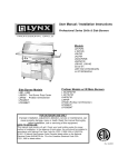
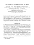
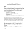
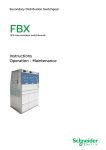
user manual pocket tools colourizer r Register you r: colourize ps.com www.aer-am rvice Se er > Custom 1 pocket tools colourizer user manual ContentsPage 2 1. Introduction 3 2. Safety Instructions 4 3. Controls and Connections 4 4. Operation Summary 5 4.1 Cabling and Starting-up 5 4.2 Level Adjustment 5 5. Functional Characteristics 5 5.1 DI Level 5 5.2 Phase 5 5.3 24V Phantom Power 5 5.4 Filter Network and Filter Stages 6 5.4.1 Tone 6 5.4.2 Enhancer 6 5.4.3 Equalizer 6 5.4.4 Frequency Poti-Rotation 7 5.4.5 Bandwidth Poti-Rotation 7 6. Technical Specifications 8 7. Circuit Diagram 9 1. Introduction Welcome to AER ! Thank you for purchasing an AER Pocket Tool. You are now the owner of a professional audio preamp, designed and manufactured to the highest pro audio technical specifications; capable of shaping, maximizing and delivering the tonal character of your instrument. At AER our complete focus, some say obsession, is on the ‘true’ reproduction of natural acoustic sound. A lifetime spent listening to and working with acoustic instruments helps us to create and refine the very best devices available; to enable you to craft your own unique acoustic identity. Make your instrument the very best it can be ... Please take a moment to read this brief manual. We want you to understand how our product works and what it can do for you. We want you to gain benefit from its many features but most of all we want you to ENJOY it! The AER Colourizer is a preamplifier for instrument or microphone (vocal or instrument microphone). You insert it into the signal chain between source and next point in the audio path (e.g. amplifier or mixing desk) to produce sound improvement – your signal will be stronger, richer and more stable. How is this achieved? – The high grade input stage we have created makes your instrument’s tone noticeably more rounded and fuller. Three individually switchable and adjustable filter systems – tone, enhancer and equalizer – may be used separately or in combination to influence sound character, harmonics and frequency spectrum. Furthermore these filters can be used to dampen natural resonant frequencies, helping to limit feedback. The AER Colourizer also provides 24V phantom power for a condenser microphone, an adjustable pro standard DI output for direct connection to a mixing desk and a phase switch. Read on and have fun! 3 2. Safety Instructions The following guidelines shall help minimize the risk of injury through fire or electric shock. mers, revolving machines, neon illumination etc. Do not lay signal cables parallel to power current cables. 1. Carefully read these safety notes before you use the device! 8. There are no user-serviceable components inside the unit. To avoid the risk of an electric shock, the unit must not be opened. All maintenance, adjustment and repair works should be carried out by qualified staff only. Any unauthorized tampering will void the 2-year warranty. 2. Keep these safety notes in a safe place. 3. Pay attention to all warnings, instructions and additional texts on the unit. 4. Do not install or use your device in close proximity to water or if you are wet yourself. 5. Use your device in a safe place where nobody can step on cables or trip over and damage them. 6. Always pull the mains plug before cleaning your device. Use only a dry cloth for cleaning. Avoid the use of detergents and do not let any liquids seep into the unit. 9. In keeping with the EMV regulations screened cables with correctly fitted connectors must be used for all signal connections. 10. Always use an earthed power supply with the correct mains voltage. If you are in doubt about the power outlets ground, have it checked by a qualified technician. 11. Cable up your device only when it is powered off. 7. Never install your device close to units with strong electromagnetic fields such as large mains transfor- 3. Controls and Connections pocket tools pocket pocket tools tools colourizer colourizer colourizer clip clip line clip mic line mic line gain gain gain mic DI level DI level DI level volume volume volume balance balance balance intensity intensity intensity intensity intensity intensity level level level bandwidth bandwidth bandwidth tone tone tone enhancer enhancer enhancer frequency f1 = 90 Hz – 1,6 kHz frequency f2 = 680 Hz – 11 kHz frequency f1 = 90 Hz – 1,6 kHz f2 Hz– –1,6 11kHz kHz f1 = = 680 90 Hz f2 = 680 Hz – 11 kHz input input input power power power dc 24 V dc 24 V dc 24 V 4 24V phantom 24V power 24V phantom phantom power power line out line out line out DI-out DI-out DI-out 1 = gnd 2 = pos 1 3 = gnd neg pos 12 == gnd 32 = = neg pos 3 = neg Top Side gain clip line/mic DI level volume phase input level control overload indicator signal source selector switch (combo socket): line: (only via jackplug) for instruments (pickup) and other line level sources mic: (only via XLR-connector) for microphones DI signal level control line out signal level control phase invert switch tone balance intensity tone balance circuit tone balance emphasis control tone balance level control enhancer intensity off/on harmonic enhancement enhancer level control enhancer activation switch equalizer level bandwidth frequency f1/f2 parametric filter network level control filter bandwidth control filter frequency control filter frequency range switch Front Side input power signal input, combo socket for 6,3 mm mono jackplug and XLR-male-connectors on/off status indicator Rear Side dc 24 V 24 V phan- tom power line out DI-out power supply connector socket (24 Volt DC) 24V phantom power switch signal output, 6.3 mm mono jack socket signal output, symmetrical, XLR socket 4. Operation Summary 4.1 Cabling and Starting-up Before connecting to the mains, please ensure that your local mains voltage (e.g. 230V in mainland Europe, 120V in the USA) is suitable for the voltage input range of the included power supply. The relevant specs and safety symbols are printed on the rear side of the unit. Note: 24V power supply The 24VDC power supply is a certified wide-range model, capable of handling input voltages between 100V and 240V. A substantial amount of research, effort and testing went into the selection of this power supply. It is critical to the function of the preamp – please use no other power supply! Also please bear in mind that any device powered from a power supply (as opposed to battery operation), may suffer interference carried by the electricity supply itself. To avoid this, always try and keep signal cables as short as possible. We have opted for a „non-earthed power supply“ (class 2 with protective insulation) in order to avoid unwanted earth or ground loops that occur when using several earthed mains powered devices in the signal chain. Please ensure that both the tone balance and the equalizer level controls are in their middle position (centre detent) and all other controls are turned all the way to the left. The pushbuttons should be off, i.e. not pushed. Make all signal cable connections as desired (e.g. instrument or microphone to input, line out to amplifier input and maybe DI out to the mixing desk input). Now you can connect the unit to the power supply. The green power control LED indicates operational readiness. 4.2 Level adjustment Note: Level adjustment By setting the level correctly we mean that the signal level in one or several devices in a signal chain is neither too high nor too low. This applies equally to all components of a unit (here tone, enhancer or equalizer included). Consequently, care must be taken that no part of the circuit is overloaded, or that distortion is unintentionally added to the signal. We have carefully designed the circuit to achieve this objective whilst also providing potentiometers (gain, level, volume) for „manual” intervention. The colourizer is equipped with a high-quality preamp which can handle line and microphone signals and has therefore a wide input sensitivity range. Using the line/mic switch, select the preamp function to suit your signal source. Mic (pressed in) is suitable for microphones. (with condenser microphones please activate 24V phantom power) Line should be used for instrument pickup systems and most other signal sources. The gain control is used to match the colourizer input stage to your signal source, ensuring optimum function with the best possible signal-tonoise ratio (SNR). Having selected the appropriate preamp function (mic or line) and with the gain controls set fully counter clockwise (minimum gain), turn up the gain whilst playing your instrument until the red clip indicator LED lights up occasionally with heavy strumming. Now turn down the gain control (or the volume control on the source) by a tiny amount to allow additional headroom for undistorted reproduction. During play, the clip control LED should only flicker intermittently at most. With line (signal sources with a sufficient input signal level) the gain controls will probably sit between minimum gain and the 10 o’clock position. It’s likely that in mic position the setting will be significantly higher. Finally the desired output level of the line output is controlled by the volume control. Please note that some of the filter stages are active and will therefore affect the overall level setting. 5. Functional Characteristics 5.1 DI level The DI-out carries a balanced preamp signal. The DI level control determines the preamp’s output signal level. 5.2 Phase The phase switch allows reversal of the phase of the output signal of the colourizer relative to the input signal by 180°, thus matching it to the phasing of other devices in your signal chain. 5.3 24V Phantom power The 24V phantom power switch is located on the rear side of the housing. This provides phantom power to the XLR input for devices that require it eg condenser mics. The 24V phantom supply of your AER device complies with the DIN EN 61398 regulations in view of a 24V phantom power supply. Please note the supplement text on page 7. 5 pocket tools colourizer clip 5.4 Filter network and filter stages A turning to the right (fig. 3) affects an increase in treble whilst at the same time reducing the bass. line mic 5.4.1 Tone Balance – How does it work? DI level volume The „tone balance“ is served by enhancer the two controls balance and intensity. The intensity control intensity balance intensity determines the degree to which bass and treble are increased simultaneously and are mixed to the original signal (parallel mode). If the intensity control is far over to the left (min, s. fig.), frequency level bandwidth then the original signal isf1not (flat). Tur= 90 Hz – influenced 1,6 kHz f2 = 680 Hz – 11 kHz ning the control to the right (--> mid --> max) mixes the relevant bass and treble mix to the original signal. level gain tone The balance control influences the relationship betinput bass and treble. If it is in middle setting, bass ween and treble are balanced. The tone balance is now in equation. (s. fig. 1) intensity max mid min 100 Hz 1 kHz 10 kHz frequency balance in right position fig. 3 level power max intensity dc 24 V In its function and signal path the tone balance is deliberately designed as a somewhat „different“ equalipocket tools colourizer zer. It offers a comfortable way of giving the original signal more zip without distorting it. Especially on those occasions, when the clipequalizer has to be used to line suppress resonance or feedback. mic DI-out 24V phantom power line out mid 5.4.2 Enhancer 1 = gnd 2 = pos 3 = neg (flat) min 100 Hz 1 kHz 10 kHz balance in middle frequency fig. 1 gain DI level volume enhancer tone The enhancer built into the colourizer adds harmonics to the source intensity balance intensity signal thereby creating more brilliance and clarity. The enhancer level can be adjusted with the intensity control. Pressing the off/on switch frequency level bandwidth will deactivate or activate the enhancer. f1 = 90 Hz – 1,6 kHz f2 = 680 Hz – 11 kHz If you turn the balance control to the left (fig. 2), the bass range is further increased, but the treble is decreased by max. 0dB. pocket tools 5.4.3 Equalizer colourizer The equalizer is a parametric filter network, adjustable from 90 Hz to 11 kHz in two ranges: f1= 90 Hz input – 1,6 kHz and f2= 680 Hz – 11 kHz. The ranges have been designed to meet the special requirements of gain DI level volume acoustictoneinstruments, microphones and other signal enhancer power sources and to allow useful and accurate signal manipulation in order to suppress resonances and feedintensity balance intensity back. The filter technology ensures a constant DI-out frequency level bandwidth bandwidth at any 24V selected frequency. clip level line mic intensity max mid f1 = 90 Hz – 1,6 kHz f2 = 680 Hz – 11 kHz dc 24 V phantom power min 100 Hz 1 kHz balance in left position 6 10 kHz frequency fig. 2 line out 1 = gnd 2 = pos 3 = neg input power Note: A parametric equalizer is a filter network where all features of a filter (amplitude, i.e. boost or cut = level, frequency and Q factor = bandwidth) can be adjusted. Parametric means that not only the boost /cut, but also the location and width of the frequency bands can be adjusted. It offers the possibility to equalize (flatten) notches or peaks in the frequency response (hence the name equalizer) and to suppress feedbacks or resonant peaks. It can also be used as a flexible tone control for targeted sound alterations. Sample application: Suppose you notice an excessive signal increase (feedback). To counteract you will need to reduce the signal level of the corresponding frequency range. To do this, first set the level control (amplitude) to maximum cut (left-hand stop). Make sure that the bandwidth control is set to maximum bandwidth (righthand stop). Using the frequency control you can now detect the centre frequency of the offending frequency range. (use the f1/f2 preselect switch also) The peak should now be gone. To enhance the sonic result, you may reduce the bandwidth (increase the Q factor) or lower the amplitude (decrease the reduction), if necessary. The control ranges of the potentiometers are not running linear and thus allow specific influence of critical ranges. (e.g. 87,5%/f1 control the range of 300 Hz) 5.4.4 Frequency poti-rotation poti-position rotation 300° lefthand stop 0% 50% 75% 87,5% 93% righthand stop 100% f1 55 Hz 100 Hz 180 Hz 300 Hz 455 Hz 870 Hz f2 600 Hz 1,3 KHz 2,3 KHz 3,7 KHz 5,6 KHz 11 KHz Supplement to article 5.3: Use of 24V- rsp. 48V-Phantom-Power (Phantom power = remote supply, here: powering an audio device via the connected audio line) Turn on the phantom power only if the unit connected to the XLR socket is designed to handle it! In general, suitable units are e.g. condenser microphones, active DI boxes and other special audio devices, whose power supply is drawn from the phantom power. Such devices are also labelled accordingly; please heed the permissible power consumption (max.10mA). High-quality dynamic microphones with a balanced signal need no phantom power, but can handle it anyway. Other devices which have not been designed explicitly for phantom power operation can suffer from considerable malfunctions, and damage may result as well. Examples of devices that may be damaged by incorrect application of phantom power include: Low-cost dynamic microphones with a mono jack plug (unbalanced signal) that were fitted afterwards with an XLR connector. Audio devices with a balanced XLR output (e.g. DI boxes, effects devices, instrument preamps with a DI output etc.) which are not protected against phantom power applied to their XLR output. (The DI connectors on AER products are protected against applied phantom power.) Other audio devices (such as preamps, effects pedals etc.) whose unbalanced line output was replaced by an XLR socket. If in doubt please consult the manufacturer of the device you are using. 5.4.5 Bandwidth poti-rotation poti-position rotation 300° octave lefthand stop 0,0% 1/6 12,5%1/3 25 % 1/2 50%2/3 righthand stop 100% 1 Experiment and enjoy your new route to alternative soundscapes! Any questions or suggestions? Please do contact us at: [email protected] Thanks for reading! 7 6.Technical Technical dataSpecifications: pocket tools colourizer Input input Tone controls Switchable microphone or line input Combo socket, XLR and ¼“ jack (6.35 mm) line mode (jack input) Unbalanced high impedance input for instrument pick-ups and line-level sources Gain adjustment range: +3…+20 dB Min. input voltage: 100 mV (–20 dBV) Max. input voltage: 3 V (+10 dBV) Input impedance: 2.2 M || 150 pF Signal-to-noise ratio (A-weighted) Min. gain: 104 dB Max. gain: 98 dB Frequency response: 20 Hz…20 kHz / 1 dB THD + N (1 kHz): < 0.3% Phantom power: Ring contact of line out is connected to ring contact of input. Any external phantom power applied at the ring of line out will be available at the input. mic mode (XLR input) Balanced microphone input 1 = ground, 2 = positive (+), 3 = negative (–) Gain adjustment range: +4…+40 dB Min. input voltage: 10 mV (–40 dBV) Max. input voltage: 3 V (+10 dBV) Input impedance: 2.1 k Unbalanced: 1.1 k Signal-to-noise ratio (A-weighted): Min. gain: 104 dB Max. gain: 95 dB Frequency response: 20 Hz…20 kHz / 1 dB THD + N (1 kHz): < 0.1% Phantom power: 24 V, R = 1.2 k per terminal, switchable, total current max. 10 mA, short circuit protected Warning: External equipment may be damaged by inappropriate use of phantom power. In case of doubt keep the 24 V phantom power switch off (not pushed). Clip indicator Red LED Headroom: 12 dB Outputs line out DI-out Unbalanced line output after master Mono jack, ¼” (6.35 mm) Nominal output voltage: 1 V (0 dBV) Max. output voltage: 9 V (+19 dBV) Output impedance: 47 Min. load impedance: 2 k Residual noise (master fully anticlockwise): A-weighted: 1.2 μV (–118 dBV) Balanced XLR output 1 = ground, 2 = positive (+), 3 = negative (–) Level control Nominal output voltage (differential), adjustment range: 41…410 mV (–28…–8 dBV) Output impedance: 47 each terminal to ground Min. load impedance (differential): 1 k Residual noise (both channels in line mode): A-weighted: 2.3 μV (–113 dBV) Tone Enhancer Parametric equalizer Flat if intensity is set fully anticlockwise. The following values apply if intensity is set fully clockwise: balance left: +9 dB at 100 Hz, shelf type balance center: +7 dB at 100 Hz, and +12 dB at 10 kHz, shelf type balance right: -1 dB at 50 Hz +12 dB at 10 kHz, shelf type Enhancer intensity fully clockwise, 1 V RMS at line out: Frequency response: +3 dB at 10 kHz Harmonic distortion: THD 10% at 1 kHz Adjustable band boost / cut (bell curve) filter Frequency range: 90 Hz…1.6 kHz / 680 Hz…11 kHz (switchable) Gain range: 15 dB at center frequency of filter Bandwidth range: 0.4 – 2.2 octaves (“half-dB” method, measured between +7.5 dB points with level set to +15 dB) Power Supply voltage Mains adapter 24 V=, 0.2 A Use only supplied mains adapter. Mains voltage: 100-240 V~ Power consumption when used with Colourizer: max. 10 W General Metal Aluminium housing Finish Anodized black Dimensions 65 mm (2.56“) high 105 mm (4.13“) wide 135 mm (5.31“) deep Weight 480 g (1.06 lbs) Definitions and conditions Input and output voltages are RMS values for a sine signal and 1 kHz unless stated otherwise. Tone controls in neutral position (equalizer level in center position, tone intensity and enhancer intensity fully anticlockwise) unless stated otherwise. Min. input voltage: Input voltage for nominal output voltage at line out with gain and volume fully clockwise. Max. input voltage: Permissible input voltage that does not cause distortion more than the rated THD + N (assuming suitable control settings). Signal-to-noise ratio (SNR): Ratio of nominal output voltage to noise voltage at line out, at specified gain setting, master fully clockwise, input shorted, 20 Hz…20 kHz. Note: SNR is specified for each channel depending on its control settings. The SNR found at line out may be less than the specified SNRs of the channels because both channels contribute to the output noise. Residual noise: Noise voltage at an output when all gain and level settings are minimal. THD + N: Total harmonic distortion + noise for nominal output voltage at line out Specifications and appearance subject to change without notice. TD20111123 8 LINE INPUT MIC 1 2 3 R T High impedance PH 1.2 k 1.2 k GAIN LINE/MIC +24 V 24 V PHANTOM POWER BALANCE INTENSITY TONE BALANCE BW FREQ. f1 f2 RANGE EQUALIZER LEVEL INTENSITY OFF/ON ENHANCER PHASE 0 / 180° CLIP DETECT VOLUME DI LEVEL CLIP PH R 3 LINE OUT DI OUT B090529B_20111114 T 1 2 7. Circuit Diagram: pocket tools colourizer 9 notes 10 notes 11 www.aer-amps.com Colourizer - 2011_11_GB 12