1
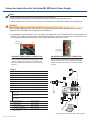
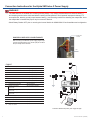
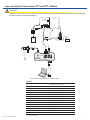
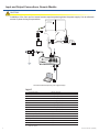
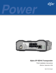
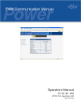
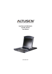
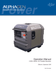
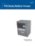
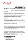
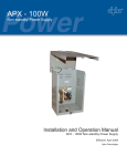
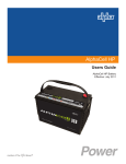
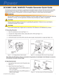
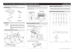
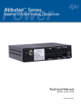
Alpha XP-EDH3 Transponder
Field Installation Instructions
Effective: February 2009
Alpha Technologies
Overview to the field installation instructions
The XP-EDH3 transponder provides the ability to manage network power through an existing cable modem
infrastructure, for a variety of power supplies as shown in this document.
These instructions provide information important to the successful installation, connection and operational verification of
the Alpha XP-EDH3 transponder in a variety of systems.
Save these instructons for future reference.
CAUTION!
Use a surge protector in the cabinet when the transformer is used to measure line voltage.
Do not place the transponder on top of the power supply or batteries.
Make all battery harness connections and connect the interface cable to the power supply before
connecting the cables to the transponder.
Before field installation, the transponder's MAC address should be loaded into the CMTS, and DOCSIS configuration file
options should be set.
Alpha XM, XM2 and AM Models
See Subsequent Sections for power supply-specific setup instructions
Power Supply Communications Card Settings
NOTE:
Alpha AM power supplies with RPM interface cards marked 700-019-28, 700-019-31 and 700-019-40 are
compatible with the DOCSIS HMS Analog Transponder.
XM - USM
XM2 - USM2
P1 = 2 & 3
SW1-1, 2, 6, 8 = On
P2, P4, P5, P6 = Closed
SW2-1, 3, 4 = On
P3 = Open
JP1 = C & 1
P7 = 5V
JP2 = 1 & 2
P8, P9, P13 = 1 & 2
P14 = N/A
XM2 - USM2.5
SW4 = 0
SW1-1, 2, 6 = On
NOTE:
Output Current switch settings are determined by the output current capability of the power supply and should be
setup accordingly. See your power supply user manual for setting details.
2
•
USM:
N/A
•
USM2:
SW1-3 = Output #1, SW1-4 = Output #2
•
USM2.5:
SW1-3 = Output Current Scaling, 15A or 22A
•
RPM:
No switch setting required
745-419-C3-001 Rev. A (02/2009)
Connection Instructions for the Alpha AM, XM Series Power Supply
NOTE:
A chipset upgrade may be required; contact Alpha for more information.
Set the jumpers and calibrate the USM card before making connections and applying the load.
1.Switch Battery Breaker OFF prior to removing the Inverter Module for USM Card installation and configuration.
WARNING!
When installing Battery Sense Cable Kit (BSC) or AlphaGuard sense cable, do not connect the black
(negative) wire of the BSC to the negative post on Battery 1.
2.It is advisable to install the Battery or Aux pwr cables (providing power to the External DOCSIS unit) and waiting until
the RDY LED is flashing normally before installing the power supply interface kit. This will reduce the chances of the
power supply transferring to inverter due to a low signal reference on the test control pin.
Tamper switch
connection point
Pin 1
Pin 1
Tamper switch
connection point
AM Series Power Supply Connection
XM Series Power Supply Connection
When connecting to an AM Series power supply, plug the 13-pin
connector so the black wire is in pin1 and two open pins are left
at the left for tamper switch connection (as viewed from the front
of the unit)..
When connecting to an XM Series power supply, plug the 13-pin
connector so the black wire is in pin1 and two open pins are left at
the bottom for tamper switch connection (as viewed from the front
of the unit).
Legend
1
Generator Interface (as needed)
Alpha p/n 874-975-20
2, 5
Battery Sense Wire Kit for:
36V single string, 6', Alpha p/n 874-842-21
36V single string, 9', Alpha p/n 874-842-27
2
36V dual string, 6', Alpha p/n 874-842-20
36V dual string, 9', Alpha p/n 874-842-28
3
1
48V single string, 6', Alpha p/n 875-841-21
48V single string, 9' Alpha p/n 875-841-25
48V dual string, 6', Alpha p/n 875-841-20
9
48V dual string, 9', Alpha p/n 875-841-24
3
Ignition Battery/Aux Power Cable
Alpha p/n 874-976-20
XM Series 2 Power Supply
Interface Cable
Alpha p/n 875-335-20 (USM2/2.5)
XM Series Power Supply
Interface Cable
Alpha p/n: 875-335-21 (USM)
AM Series Power Supply
Interface Cable
Alpha p/n: 875-335-21 (RPM)
6
Craft Port Cable (optional)
Alpha p/n 875-349-10
7
RTS Cable (optional)
Alpha p/n 745-178-21
8
Vin Sense (optional)
Alpha p/n 875-493-21
9
Surge Protector Ground Block
Alpha p/n 162-028-10
10
Plug-in Lightning Arrestor w/pass thru
(130V) l-G, l-n, N-G
Alpha p/n 162-046-10
4
10
4
8
5
6
7
Connections between transponder, power supply and laptop
745-419-C3-001 Rev. A (02/2009)
3
Connection Instructions for the Alpha XM Series 2 Power Supply
WARNING!
The XM2 batteries are isolated from chassis ground by design. Any voltage potential difference between battery (-)
and chassis ground must be eliminated before installing the transponder to avoid potential transponder damage. To
accomplish this, attach a ground jumper between battery (-) and chassis ground before installing the transponder. Once
the transponder is installed the jumper may be removed if desired.
Switch Battery Breaker OFF prior to removing the Inverter Module for USM2/USM2.5 Card installation and configuration.
Tamper switch
connector
XM Series 2 Power Supply Connection NOTE:
When connecting to an XM Series 2 power supply, plug the 13-pin
connector so the black wire is in pin1 and two open pins are left at
the top for tamper switch connection.
Pin 1
Legend
1
Generator Interface (as needed)
Alpha p/n 874-975-20
2, 5
Battery Sense Wire Kit for:
36V single string, 6', Alpha p/n 874-842-21
2
36V single string, 9', Alpha p/n 874-842-27
36V dual string, 6', Alpha p/n 874-842-20
3
1
36V dual string, 9', Alpha p/n 874-842-28
48V single string, 6', Alpha p/n 875-841-21
48V single string, 9' Alpha p/n 875-841-25
48V dual string, 6', Alpha p/n 875-841-20
9
48V dual string, 9', Alpha p/n 875-841-24
3
Ignition Battery/Aux Power Cable
Alpha p/n 874-976-20
XM Series 2 Power Supply
Interface Cable
Alpha p/n 875-335-20 (USM2/2.5)
XM Series Power Supply
Interface Cable
Alpha p/n: 875-335-21 (USM)
AM Series Power Supply
Interface Cable
Alpha p/n: 875-335-21 (RPM)
6
Craft Port Cable (optional)
Alpha p/n 875-349-10
7
RTS Cable (optional)
Alpha p/n 745-178-21
8
Vin Sense (optional)
Alpha p/n 875-493-21
9
Surge Protector Ground Block
Alpha p/n 162-028-10
10
Plug-in Lightning Arrestor w/pass thru
(130V) l-G, l-n, N-G
Alpha p/n 162-046-10
4
10
8
4
6
5
7
Connections between transponder, power supply and laptop
4
745-419-C3-001 Rev. A (02/2009)
Input and Output Connections, ZTT and ZTT+ Models
CAUTION!
Installation of the Vout and Iout sense harness requires powering down the power supply. Use an alternate
source of power during this procedure.
ZTT/+
4
7
9
5
SPI
1
8
2
6
2
3
Connections between transponder, power supply and laptop
Legend
1
2
Power Supply Interface
Alpha P/N: 875-335-22 (ZTT and ZTT+ Post 1998)
Alpha P/N: 875-335-23 (ZTT+ Pre 1998)
Battery Sense Wire Kit for:
36V single string, 6', Alpha p/n 874-842-21
36V single string, 9', Alpha p/n 874-842-27
36V dual string, 6', Alpha p/n 874-842-20
36V dual string, 9', Alpha p/n 874-842-28
48V single string, 6', Alpha p/n 875-841-21
48V single string, 9' Alpha p/n 875-841-25
48V dual string, 6', Alpha p/n 875-841-20
48V dual string, 9', Alpha p/n 875-841-24
745-419-C3-001 Rev. A (02/2009)
3
Craft Port Cable (optional)
Alpha p/n 875-349-10
4
RTS Cable (optional)
Alpha p/n 745-178-21
5
Vin Sense (optional)
Alpha p/n 875-493-21
6
Surge Protector Ground Block
Alpha p/n 162-028-10
7
Vout Iout Sense Harness
Alpha p/n 875-456-10
8
Tamper Wire Kit
Alpha p/n 875-493-21
9
Plug-in Lightning Arrestor w/pass thru
(130V) l-G, l-n, N-G
Alpha p/n 162-046-10
5
Input and Output Connections, Generic Models
CAUTION!
Installation of the Vout and Iout sense harness requires powering down the power supply. Use an alternate
source of power during this procedure.
4
7
9
5
1
SPI
8
2
6
2
3
Connections between transponder, power supply and laptop
Legend
1
Power Supply Interface
Alpha P/N: 875-335-25
2
Battery Sense Wire Kit for:
36V single string, 6', Alpha p/n 874-842-21
36V single string, 9', Alpha p/n 874-842-27
36V dual string, 6', Alpha p/n 874-842-20
36V dual string, 9', Alpha p/n 874-842-28
48V single string, 6', Alpha p/n 875-841-21
48V single string, 9' Alpha p/n 875-841-25
48V dual string, 6', Alpha p/n 875-841-20
48V dual string, 9', Alpha p/n 875-841-24
6
3
Craft Port Cable (optional)
Alpha p/n 875-349-10
4
RTS Cable (optional)
Alpha p/n 745-178-21
5
Vin Sense (optional)
Alpha p/n 875-493-21
6
Surge Protector Ground Block
Alpha p/n 162-028-10
7
Vout Iout Sense Harness
Alpha p/n 875-456-10
8
Tamper Wire Kit
Alpha p/n 875-493-21
9
Plug-in Lightning Arrestor w/pass thru
(130V) l-G, l-n, N-G
Alpha p/n 162-046-10
745-419-C3-001 Rev. A (02/2009)
Verifying Installation and Network Connectivity (applies to all power supplies)
Method 1: Status LEDs
After the initial transponder power-up, network communication can be verified by the following behavior:
Rx LED on Solid, occasionally flickering off, indicating CMTS communication
Tx LED off, but will flicker when transmitting data to CMTS
Method 2: Local Port using Craft Port Cable, Alpha P/N: 875-349-10
Connect laptop to ‘Local’ port and set terminal emulator software settings to:
19200 Baud; 8-N-1; No Flow Control
Type >STATUS for transponder IP Address
Type >PSDATA 1 for power supply measurements
Method 3: Remote via HTTP Web Page
Place IP Address into Internet Web Browser to verify remote HTTP communication
Method 4: Remote via SNMP (Simple Network Management Protocol)
Use SNMP MIB Browser software to query power supply’s input voltage. [OID: 1.3.6.1.4.1.5591.1.4.2.1.23.1]
A valid response verifies remote SNMP communication.
745-419-C3-001 Rev. A (02/2009)
7
Power
Alpha Technologies
®
Alpha Technologies
3767 Alpha Way
Bellingham, WA 98226
USA
Tel: +1 360 647 2360
Fax: +1 360 671 4936
Web: www.alpha.com
Alpha Technologies Ltd.
4084 McConnell Court
Burnaby, BC, V5A 3N7
CANADA
Tel: +1 604 430 1476
Fax: +1 604 430 8908
Alpha Technologies
Europe Ltd.
Twyford House Thorley
Bishop's Stortford
Hertfordshire CM22 7PA
UNITED KINGDOM
Tel: +44 0 1279 501110
Fax: +44 1 279 659870
Alpha Technologies GmbH
Hansastrasse 8
D 91126 Schwabach
GERMANY
Tel: +49 9122 79889 0
Fax: +49 9122 79889 21
Alphatec, Ltd
339 St. Andrews Street
Suite 101 Andrea Chambers
3307 Limassol
CYPRUS
Tel: +357 25 375675
Fax: +357 25 359595
AlphaTEK ooo
Khokhlovskiy Pereulok 16
Stroenie 1, Office 403
109028 Moscow
RUSSIA
Tel: +7 495 916 1854
Fax: +7 495 916 1349
Alphatec Baltic
S. Konarskio Street G.49-201
Vilnius LT-03123
LITHUANIA
Tel: +370 5 210 5291
Fax: +370 5 210 5292
Alpha Technologies
34, Grande Rue
Bétheny, F-51450
France
Phone: +33 32 64990 54
Fax: +33 67 54289 44
Due to continuing product improvements, Alpha reserves the right to change specifications without notice.
Copyright © 2009 Alpha Technologies, Inc. All rights reserved. Alpha is a registered trademark of Alpha Technologies. 745-419-C3-001, Rev. A.