1
Traffic Monitor Trailers, Configuration and Deployment
Final Report
by
Larry Hayden, Research Associate II
Western Transportation Institute
College of Engineering, Montana State University
Prepared for the
US Department of Transportation
Research and Innovative Technology Administration
Washington, D.C.
August, 2007
Traffic Monitor Trailers, Configuration and Deployment
Disclaimer
DISCLAIMER
Alternative accessible formats of this document will be provided upon request. Persons with
disabilities who need an alternative accessible format of this information, or who require some
other reasonable accommodation to participate, should contact Kate Heidkamp, Assistant
Director for Communications and Information Systems, Western Transportation Institute,
Montana State University, PO Box 174250, Bozeman, MT 59717-4250, telephone number 406994-7018, e-mail: [email protected]
Western Transportation Institute
ii
Traffic Monitor Trailers, Configuration and Deployment
Acknowledgements
ACKNOWLEDGEMENTS
Thanks to Andrew Edwards and Andy Lingley, MSU senior engineering students, for assistance
with assembly, testing, and troubleshooting the cameras and wireless communication system and
contributions to this report.
Thanks to MSU engineering student Gary Schoep for help with trailer assembly, testing and
troubleshooting, plus assistance with configuring the campus network interface and contributions
to this report.
Thanks to students Justin Krohn for contributions to the campus network connection and Jack
Allison for the pictures of the Access Point location.
Thanks to Suzanne Lassacher and Doug Galarus of WTI for insightful discussions that improved
the project results and this report. Also, thanks to MSU professors Ahmed Al-Kaisy and Richard
Wolff for helpful discussions and assistance in locating equipment and documentation of the
previous work.
Western Transportation Institute
iii
Traffic Monitor Trailers, Configuration and Deployment
Table of Contents
TABLE OF CONTENTS
1.
Introduction..............................................................................................................................1
2.
Design ......................................................................................................................................2
2.1.
2.1.1.
Tip-up/Crank-up Mast ............................................................................................ 2
2.1.2.
Equipment Cabinet.................................................................................................. 2
2.1.3.
Solar Power System ................................................................................................ 3
2.2.
Solo Pro................................................................................................................... 6
2.2.2.
AIS .......................................................................................................................... 8
Communications ........................................................................................................... 10
2.3.1.
Access Point.......................................................................................................... 10
2.3.2.
Subscriber Module ................................................................................................ 12
2.3.3.
Device Server........................................................................................................ 14
Assembly/Installation ............................................................................................................15
3.1.
AutoScope Cameras...................................................................................................... 15
3.1.1.
Solo Pro Camera ................................................................................................... 15
3.1.2.
AIS Camera........................................................................................................... 19
3.1.3.
AutoScope Network Browser ............................................................................... 20
3.2.
4.
Cameras........................................................................................................................... 5
2.2.1.
2.3.
3.
Trailers ............................................................................................................................ 2
Communications ........................................................................................................... 30
3.2.1.
Canopy Configuration........................................................................................... 30
3.2.2.
Subscriber Module ................................................................................................ 31
3.2.3.
Access Point.......................................................................................................... 32
3.2.4.
Device Server........................................................................................................ 33
Deployment and Test .............................................................................................................36
4.1.
Locations....................................................................................................................... 36
4.1.1.
South 7th and Kagy Intersection........................................................................... 36
4.1.2.
11th and Kagy Intersection ................................................................................... 36
4.1.3.
11th and College Intersection ............................................................................... 36
4.1.4.
South 7th Intersection ........................................................................................... 36
4.2.
Testing........................................................................................................................... 36
4.2.1.
Plan ....................................................................................................................... 36
Western Transportation Institute
Page iv
Traffic Monitor Trailers, Configuration and Deployment
4.2.2.
Table of Contents
Results................................................................................................................... 37
5.
Recommendations..................................................................................................................45
6.
Appendix A CCTV TRailer Quick Reference User’s Guide................................................47
6.1.
Tool List........................................................................................................................ 47
6.2.
Deployment Equipment List ......................................................................................... 47
6.3.
Trailer Preparation ........................................................................................................ 47
6.4.
Trailer Stabilization and Leveling System.................................................................... 48
6.4.1.
Stabilization .......................................................................................................... 48
6.4.2.
Leveling ................................................................................................................ 48
6.5.
Camera Installation & Removal.................................................................................... 49
6.5.1.
Installation............................................................................................................. 49
6.5.2.
Removal ................................................................................................................ 49
6.6.
Canopy Antenna Installation & Removal ..................................................................... 50
6.6.1.
Installation............................................................................................................. 50
6.6.2.
Removal ................................................................................................................ 50
6.7.
Mast Operation.............................................................................................................. 51
6.7.1.
Raise Mast............................................................................................................. 51
6.7.2.
Lower Mast ........................................................................................................... 51
6.8.
Enabling/Disabling Power System ............................................................................... 52
6.8.1.
Enable ................................................................................................................... 52
6.8.2.
Disable .................................................................................................................. 52
6.9.
Aiming the cameras and antenna. ................................................................................. 52
6.10.
Deploying the Solar Panels....................................................................................... 52
6.10.1.
Deploying.............................................................................................................. 52
6.10.2.
Storing................................................................................................................... 53
6.11.
Storing the Trailers ................................................................................................... 53
6.12.
Troubleshooting ........................................................................................................ 53
6.12.1.
SM Configuration - Wireless Access.................................................................... 53
6.12.2.
AutoScope Browser .............................................................................................. 53
7.
Appendix B: Major Parts List ...............................................................................................54
8.
Appendix C: Auxiliary Files..................................................................................................55
9.
References..............................................................................................................................57
Western Transportation Institute
Page v
Traffic Monitor Trailers, Configuration and Deployment
List of Tables
LIST OF TABLES
Table 1: Camera and Panel Connector Pinout. ............................................................................. 17
Table 2: Camera Cable Pinout for ACIP. ..................................................................................... 18
Table 3: ACIP Downstream (Supervisor) to Upstream Network Connection.............................. 18
Table 4: Supervisor ACIP to RackVision Connection. ................................................................ 18
Table 5: Supervisor RackVision™ Module Status Lights............................................................ 20
Table 6: Second RackVision™ Module Status Lights. ................................................................ 20
Table 7: SM Status Lights............................................................................................................. 32
Table 8: DeviceMaster RTS LED Indicator Lights. ..................................................................... 33
Table 9: Session Status Results for University Way and Kagy. ................................................... 39
Table 10: Session Status Results for 11th & Kagy. ...................................................................... 41
Table 11: Session Status Results for 11th and College................................................................. 43
Western Transportation Institute
Page vi
Traffic Monitor Trailers, Configuration and Deployment
List of Figures
LIST OF FIGURES
Figure 1: Equipment Cabinet as Supplied by the Manufacturer..................................................... 3
Figure 2: Four of Eight Batteries and the Controller. ..................................................................... 4
Figure 3: Stored Solar Panels.......................................................................................................... 4
Figure 4: Solar Panels Deployed..................................................................................................... 5
Figure 5: AutoScope AIS Camera courtesy of the Autoscope website. ......................................... 6
Figure 6: Solo Pro Cabinet.............................................................................................................. 7
Figure 7: AIS Cabinet. .................................................................................................................... 8
Figure 8: 110V AC Power for AIS Cameras. ................................................................................. 9
Figure 9: AP and Antenna Array on Cobleigh Hall...................................................................... 10
Figure 10: Antenna Coverage Map (on the Inside of the Antenna Control Panel Cover)............ 11
Figure 11: AP Antenna Control Panel in 604 Cobleigh Hall........................................................ 12
Figure 12: SM Mounting Bracket Attached to Lower Mast Section. ........................................... 12
Figure 13: SM Mounted to T-cap. ................................................................................................ 13
Figure 14: SM Attachment to T-cap Detail. ................................................................................. 14
Figure 15: Solo Pro Trailer Wiring Diagram................................................................................ 16
Figure 16: ACIP for Solo Pro Cameras. ....................................................................................... 17
Figure 17: AIS Trailer Wiring Diagram. ...................................................................................... 19
Figure 18: Error Message.............................................................................................................. 21
Figure 19: End Program Message................................................................................................. 21
Figure 20: Add a New TCP/IP Socket Channel............................................................................ 22
Figure 21: Configuring a TCP/IP Socket Channel for the Pro Cameras. ..................................... 22
Figure 22: Learn Dialog Box. ....................................................................................................... 23
Figure 23: Learning the Socket Channel. ..................................................................................... 23
Figure 24: Learning the Socket Channel Progress........................................................................ 24
Figure 25: Failure of the Learn Process........................................................................................ 24
Figure 26: Manually Update Camera Software. ........................................................................... 25
Figure 27: Autoscope Network Browser. ..................................................................................... 25
Figure 28: Autoscope Detector Editor Toolbar. ........................................................................... 26
Figure 29: Count Detector. ........................................................................................................... 28
Figure 30: Count Detector Parameters.......................................................................................... 28
Figure 31: Editing Detector Members. ......................................................................................... 29
Western Transportation Institute
Page vii
Traffic Monitor Trailers, Configuration and Deployment
List of Figures
Figure 32: Label Detector Volume Selection. .............................................................................. 30
Figure 33:Tower with AP on the Roof of Cobleigh Hall.............................................................. 32
Figure 34: AP Zone 3 Antenna Interference Levels. .................................................................... 37
Figure 35: AP Zone 1 Antenna Interference Levels. .................................................................... 38
Figure 36: Session Status for South 7th and Kagy - Zone 3......................................................... 39
Figure 37: Link Capacity Test Results for Zone 3........................................................................ 40
Figure 38: Session Status for 11th and Kagy - Zone 3. ................................................................ 41
Figure 39: Link Capacity Test Results for Zone 3........................................................................ 42
Figure 40: Session Status Results for 11th and College – Zone 3. ............................................... 43
Figure 41: Link Capacity Test Results for Zone 3........................................................................ 44
Figure 42: Beware of Mast. .......................................................................................................... 48
Figure 43: Bull’s-Eye Level.......................................................................................................... 49
Figure 44: Extending Mast............................................................................................................ 51
Figure 45: Switch Box Control Schematic 5. ............................................................................... 55
Figure 46: RF Switch Box Schematic 5........................................................................................ 56
Western Transportation Institute
Page viii
Traffic Monitor Trailers, Configuration and Deployment
List of Abbreviations
LIST OF ABBREVIATIONS
AC
Alternating Current
ACIPS
Autoscope Communication Interface Panels
AES
Advanced Encryption Standard
AIS
Autoscope Image Sensor
AP
Access Point
BNC
bayonet Neill-Concelman
CCTV
Closed Circuit Television
CE
Civil Engineering
CNUT
Canopy Network Update Tool
DC
Direct Current
DHCP
Dynamic Host Configuration Protocol
EV-DO
Evolution Data Optimized
FHWA
Federal Highway Administration
GFCI
Ground Fault Circuit Interrupter
GPS
Global Positioning System
IE
Internet Explorer
ITC
Information Technology Center
LOS
Line of Sight
MSU
Montana State University
MVP
Machine Vision Processor
NTSC
National Television Standards Committee
PI
Principal Investigator
POE
Power Over Ethernet
PTZ
Pan/Tilt/Zoom
RF
Radio Frequency
RSSI
Received Signal Strength Indication
SM
Subscriber Module
TMC
Traffic Management Center
UTC
University Transportation Center
WTI
Western Transportation Institute
Western Transportation Institute
Page ix
Traffic Monitor Trailers, Configuration and Deployment
Introduction
1. INTRODUCTION
The Western Transportation Institute (WTI) Trailer Configuration and Deployment Project was
created by a desire to improve Bozeman traffic flow, particularly during campus events. Closedcircuit television (CCTV) cameras, a wireless communication system, and portable mast trailers
with solar power had been obtained by the Civil Engineering (CE) department at Montana State
University (MSU) for student traffic study projects. A Motorola Canopy Access Point (AP) for
the wireless communication system was designed and installed in 2005. The communication
system was tested by students at several locations within the city of Bozeman with temporary
antenna mounts but the portable mast trailers were not available until the summer of 2006. This
project was initiated in September 2006 by the vision and support of Steve Albert, WTI Director,
with a proposal (written by the Principal Investigator (PI)) that documented the capabilities and
limitations of the available equipment for the purpose of integrating and testing the trailers,
cameras, and communication system. Funding for the effort was obtained in October 2006
through WTI’s Federal Highway Administration (FHWA) – University Transportation Center
(UTC) grant. The project involved designing, fabricating, and installing fixtures and cabling to
mount two AutoScope cameras and a Motorola Canopy Subscriber Module (SM) on each
portable mast trailer. The trailers would be used for transmitting traffic information back to the
campus network for access by the Civil Engineering (CE) transportation lab or the WTI virtual
traffic management center (TMC). The Trailer Configuration and Deployment project contract
was closed in August 2007. The mobile traffic data collection system is expected to have a
lifespan of many years, but may require upgrades due to the rapidly changing technology.
This document is divided into five main sections; Introduction, Design, Assembly,
Recommendations, and Quick Users Guide. The Introduction section describes the impetus and
focus of the project. The Design section details the integration issues encountered, possible
solutions, reasons for the option(s) chosen, and notes on the results. The Assembly section
provides details for all connection and setup issues. The Recommendation section provides
insight for building an optimal mobile traffic monitoring system from scratch. Finally, the Quick
Users Guide provides instructions to successfully deploy the trailers.
Western Transportation Institute
Page 1
Traffic Monitor Trailers, Configuration and Deployment
Design
2. DESIGN
The trailers are intended for unattended traffic monitoring with real time communication to the
CE transportation lab or WTI virtual TMC. They may be deployed in any season at locations
where a reliable communication link can be established and maintained.
This section documents the system design issues encountered, solutions considered and solution
implemented for the trailers, cameras, and communication components. Since the major
components of the system had already been obtained, design decisions were related to
component integration, deployment considerations and trailer storage issues.
Note: Section Three Assembly/Installation - documents the detailed connections between the
components and the configuration/setup software.
2.1.
Trailers
The trailers were equipped with a tip-up/crank-up mast, optional equipment cabinet, and solar
charged battery power supply. The trailers also have bolted on weights and outriggers with
extendable legs for stability.
2.1.1.
Tip-up/Crank-up Mast
The top of the mast is two inch square tubing. Two cameras and potentially one Canopy antenna
were to be mounted on the mast. The mounting hardware supplied for the cameras was designed
for a horizontal mast orientation and it was soon apparent that new mounting hardware was
needed for either the cameras or the mast. A mast T-cap solution was selected as it allowed the
cameras to be easily removed for transport and storage. Camera removal from the trailers
requires only the removal of the T-cap. The Canopy antenna may be mounted on the center post
of the T-cap or on the top of the lower fixed mast section (as seen on the cover photo). The Tcaps were ordered from the trailer manufacturer, O.M.J.C. Signal, Inc.
NOTE: The mast can be rotated when vertical but must be returned to its’ original position
before it can be lowered.
2.1.2.
Equipment Cabinet
A 16”x13”x17” lockable equipment cabinet containing a factory installed inverter and battery
charger is mounted to the back of each trailer (Figure 1). The Direct Current (DC)-to-Alternating
Current (AC) inverter is mounted on the cabinet’s left side and the battery charger is mounted on
the cabinet’s right side. An opening with a hinged cover for cable access is located on the bottom
right front corner of the cabinet as seen in Figure 1. Additional cabinet components include:
•
Autoscope Communication Interface Panels (ACIPs) or RackVision™ modules;
•
Motorola Canopy and/or Autoscope lightning surge suppression units;
•
1 device server;
•
2 - 4 DC power supplies; and
•
1 power strip.
Cabinet equipment integration is discussed in Section 3.
Western Transportation Institute
Page 2
Traffic Monitor Trailers, Configuration and Deployment
Design
NOTE: Although the equipment will be grounded to the trailer, the trailer is not likely to have a
good lightning ground. A good lightning or electrical ground is generally considered a 5/8”
diameter copper or steel rod driven at least 8 feet into the ground and connected with a 6 gauge
copper cable. This is not apt to happen in a mobile trailer environment. Furthermore in many
locations where the trailers might be deployed, it might be impractical or impossible to drive a
ground rod. Some grounding will be provided by the legs through the jacks depending on the
material the legs contact.
Figure 1: Equipment Cabinet as Supplied by the Manufacturer.
2.1.3.
Solar Power System
Power is provided by eight, deep cycle 12V solar batteries charged by two 125 watt solar arrays.
The batteries are housed in two separate lockable covered aluminum boxes. The batteries,
weighing about 70 pounds each, also supply ballast to stabilize the trailer when the mast is
deployed. One set of batteries and the charge controller are shown in Figure 2. 1
Western Transportation Institute
Page 3
Traffic Monitor Trailers, Configuration and Deployment
Design
Figure 2: Four of Eight Batteries and the Controller.
Two solar arrays are stored back-to-back (Figure 3) and continually charge the batteries when
solar is available. The solar arrays are mounted to enable both arrays to be positioned to face the
sun when the mast is vertical (Figure 4).
Figure 3: Stored Solar Panels.
Western Transportation Institute
Page 4
Traffic Monitor Trailers, Configuration and Deployment
Design
Figure 4: Solar Panels Deployed.
2.2.
Cameras
A total of four AutoScope cameras were obtained for the trailers: two Autoscope Solo Pro and
two Autoscope Image Sensor (AIS) cameras (Figure 5). Prior to implementation the decision was
made to match the models deployed on each trailer. In hindsight, it might have been better to
place one of each camera model on each trailer. This would have made the camera assemblies
and cables identical for each trailer, thereby lessening the chance of confusion and errors when
selecting cameras and cables for trailer deployment.
Western Transportation Institute
Page 5
Traffic Monitor Trailers, Configuration and Deployment
Design
Figure 5: AutoScope AIS Camera courtesy of the Autoscope website.
2.2.1.
Solo Pro
AutoScope Solo Pro models have a machine vision processor (MVP) built into the camera body.
This makes the camera about 5 inches longer than the AIS model but otherwise visually the
same. Only one short camera cable assembly and 100 feet of bulk camera cable were acquired,
so two 40 foot cable assemblies were purchased to connect the Solo Pro cameras to the ACIP.
(The masts extend to 35 feet in height.) As purchased, the cables had an 18-pin circular
connector for the camera end and flying leads for the screw terminal end of the ACIP. 2
Western Transportation Institute
Page 6
Traffic Monitor Trailers, Configuration and Deployment
Design
Figure 6: Solo Pro Cabinet.
Two ACIP modules were mounted on the back of the cabinet to minimize exposure to inclement
weather such as rain and snow, and to avoid unnecessary physical contact. The ACIPs are rotated
180 degrees from one another to simplify cable connections between them.
NOTE: This worked well but may be improved if both ACIPs were moved one inch towards the
center of the cabinet making connection of the 110V AC cables easier. The 110V AC cable
connections are hidden from view in Figure 6.
Panel mount 18-pin camera connectors (and protective covers) were added to the cabinet to
enable cable removal for storage. The same 18-pin connector type used on the camera was
selected for the cabinet panel connector to simplify camera connection. This required adding a
second 18-pin connector to the cable assembly but allowed the cables to be easily detached and
stored with the cameras. Inside the cabinet a short jumper cable connects the panel mount
connector to the ACIP. The panel mount connectors protect the cameras from wiring error
damage each time the trailers are deployed. Due to cabinet space limitations, it is not possible to
store both cables in the cabinet without disconnecting them prior to storage.
NOTE: The camera will not power up if the incorrect camera is used for the cable assembly.
An in-line coupler was added to the SM Ethernet cable to avoid the need to remove and replace
the Ethernet surge suppression cover each time the trailer is deployed (or possibly bypassed and
the surge suppression not used at all). A short 10 gauge wire is used to connect the surge
suppression module to the cabinet.
Western Transportation Institute
Page 7
Traffic Monitor Trailers, Configuration and Deployment
Design
Power strips that accommodate four DC power supplies and a two standard 110V AC plugs were
purchased at a local hardware store. The power strip was mounted on the bottom of the cabinet,
towards the back eliminating the need to secure each DC power supply to the power strip, which
would have been required if the power strip had been mounted on the side wall. (Unsecured
power supplies may have fallen out of a wall mounted power strip from the jarring during trailer
movement.) The device server was mounted on the cabinet back to avoid contact with any
moisture on the bottom of the cabinet and provide short/easy cable connections. All cables are
tied down with cable ties or adhesive backed mounts with cable ties to minimize wire breakage
and improve neatness.
2.2.2.
AIS
AutoScope AIS camera models use a RackVision™ MVP module for video detection. 3 The
RackVision™ module slides into a detector rack and provides detection for the AIS camera (or
any CCTV camera that meets minimum performance standards). The module has the potential to
jar loose from the enclosure during transport as it is not secured in the enclosure. To prevent the
module from jarring loose, a large rubber band was used to hold the module in place. The same
rubber band may also be used to secure the power connector, which also has a tendency to come
loose, to the back of the enclosure (Figure 7). The rubber band, although not elegant, is a simple
and cost effective solution. The cable assembly for the AIS camera / RackVision™ combination
has the same 18-pin camera connector as the Solo Pro camera. The primary difference is that the
cable assembly for the AIS camera uses two cables.
NOTE: The camera will not power up if the camera used is not the correct camera for the cable
assembly.
Figure 7: AIS Cabinet.
Western Transportation Institute
Page 8
Traffic Monitor Trailers, Configuration and Deployment
Design
A three wire 110V AC cable provides power to the camera. A separate 75 ohm coaxial cable
provides video. The 110V AC cable requires a three prong connector and the coaxial cable
requires a 75 ohm male bayonet Neill-Concelman (BNC) connector. Neither connector was
supplied with the cable assembly
Since both 110V AC connectors would not fit through the access hole, an external 110V AC
outlet or second access hole was needed. Given that another access hole would increase the
possibility of water, dust or snow entering the cabinet, an 110V exterior outlet was deemed to be
the best solution. A ground fault circuit interrupter (GFCI) outlet was installed to help protect
against shock or electrocution (Figure 8). It is important to note that the GFCI power source
will handle the power requirements of the cameras but will not operate anything over 250
watts (about 2 amps AC). 4 A cover with a gasket was included to protect the outlet from the
elements. The 110V AC outlet enables simple camera power connection and minimizes the
number of access holes in the cabinet.
Figure 8: 110V AC Power for AIS Cameras.
A male DB9 D-Sub connector labeled “supervisor” on the RackVision™ modules front panel
provides a serial connection port for a computer or network. An RJ45 connector port labeled
“ACIP” is used to connect two RackVision™ cards, allowing a single computer or network
connection to access both cards.
The power strip accommodates four DC power supplies, three of which are fairly large, and a
standard 110V AC plug. To prevent the DC power supplies from disconnection from the power
strip during transport, the power strip was mounted to the bottom of the cabinet. Although not
evident from Figure 8, the power strip was placed near the back of the cabinet to minimize
contact with water or snow when the door was open. Mounting the power strip on the bottom of
cabinet did not leave enough space to also mount both RackVision™ enclosures on the cabinet
bottom, nor was there a practical way to mount the enclosures on the cabinet side. As a result, a
Western Transportation Institute
Page 9
Traffic Monitor Trailers, Configuration and Deployment
Design
shelf was designed and built to mount the RackVision™ cabinets in the center of the equipment
cabinet above the power strip.
2.3.
Communications
A 900 MHz Motorola Canopy system consisting of one connectorized access point (AP) and two
subscriber modules (SM) had been purchased for communication between the trailers and the
transportation lab in 426 Cobleigh Hall at Montana State University. The AP and an antenna
array with switching system had been designed and installed on a tower on the roof of Cobleigh
Hall (Figure 9). Control for the antenna switching system is located in 604 Cobleigh Hall and the
AP Ethernet connection is located in the network closet of 622a Cobleigh Hall (ECE
Stockroom).
Figure 9: AP and Antenna Array on Cobleigh Hall.
2.3.1.
Access Point
The AP is a 900 MHz Motorola Canopy connectorized (i.e. it does not have or is not using an
internal antenna) transceiver connected to the antenna switching system. The switching system
can connect the AP to any of the three antennas individually or to the antenna pair to the left of
the switching system (Figure 9). Ethernet and control cables are strung down the inside of the
tower, passing through the wall and into an elevator shaft to a network room and lab on 6th floor
of Cobleigh Hall. The cables, antenna system and AP were previously installed by MSU
Electrical and Computer Engineering (ECE) EE492 senior projects. 5
Western Transportation Institute
Page 10
Traffic Monitor Trailers, Configuration and Deployment
Design
Figures 10 and 11 show the AP antenna coverage map and antenna control panel, respectively.
When the System Power is “on”, the selected zone switch button is illuminated.
Figure 10: Antenna Coverage Map (on the Inside of the Antenna Control Panel Cover).
Western Transportation Institute
Page 11
Traffic Monitor Trailers, Configuration and Deployment
Design
Figure 11: AP Antenna Control Panel in 604 Cobleigh Hall.
The antenna RF switch latches in position, maintaining a connection to one antenna until another
antenna is selected with the control panel.
2.3.2.
Subscriber Module
SMs are mounted on the trailer mast and must be pointed at the AP for optimum performance.
The SM may only be mounted on the top or bottom sections of the mast to avoid interference
with mast operation. A SM must be mounted on the mast before the mast is jacked into the
vertical position to avoid using a ladder to access the mounting location. The mounting
hardware, consisting of a square U-bolt and 3/8” diameter serrated whiz nuts, was chosen to
facilitate installation and removal (Figure 12).
Figure 12: SM Mounting Bracket Attached to Lower Mast Section.
Western Transportation Institute
Page 12
Traffic Monitor Trailers, Configuration and Deployment
Design
To avoid having custom U-bolts fabricated, it was necessary to make some modifications. The
bracket holes were 5/16” diameter and spaced 3.5” apart. This required enlarging the holes to
3/8” diameter and slotting the holes to work with the available 3” square U-bolts or bending the
U-bolts out slightly to match the 3.5” hole spacing. Slots are more elegant, so the first bracket’s
holes were slotted to fit the 3” U-bolts. Due to the difficulty of making the slots the second
bracket’s holes were not slotted, instead the second bracket’s U-bolts were bent out slightly to
match the 3.5” hole spacing.
Attaching the SM to the lower mast section is simplest and will work in many locations. If a
connection cannot be established, the SM may need to be mounted higher on the mast. This is
accomplished by removing the SM bracket from the lower section and attaching it to the T-cap
using one of the square U-bolts and a pair of J-bolts (see Figure 13). The J-bolts (normally stored
on the T-cap) are needed to attach the bracket high enough not to interfere with T-cap mounting.
It is also necessary to use a block of wood or some other material as a spacer behind the square
U-bolt so that the nuts can be tightened (Figure 14)
Figure 13: SM Mounted to T-cap.
Western Transportation Institute
Page 13
Traffic Monitor Trailers, Configuration and Deployment
Design
Figure 14: SM Attachment to T-cap Detail.
2.3.3.
Device Server
The SM has an Ethernet port and the AutoScope hardware has a serial port; therefore, a device
server is needed to interface a SM with the AutoScope ACIP and RackVision™ modules. The
Comtrol DeviceMaster RTS is a single port device server with bi-directional conversion of serial
RS-232, RS-422 or RS-485 to 10/100Base-T Ethernet. The serial interface is software-selectable
and in this case RS-232 is used to interface with the ACIP and RackVision™ modules. 6
PortVision™ software is used to setup the device and manage changes. This is discussed in
greater detail in section 3.2.4.
Western Transportation Institute
Page 14
Traffic Monitor Trailers, Configuration and Deployment
Assembly/Installation
3. ASSEMBLY/INSTALLATION
This section will discuss the assembly/installation details including:
•
component connections;
•
software installation and configuration;
•
cable types;
•
connector types and;
•
connector pinouts of the cables used in assembling the trailers.
Most, but not all, of the information is applicable to both trailers. The camera system and
components are unique to each trailer. The trailer with the Solo Pro cameras is the “Solo Pro
trailer” and the other is the “AIS trailer”.
3.1.
AutoScope Cameras
Autoscope Network Browser software must be used to test and configure the cameras. A detailed
description of the software is provided in section 3.1.3. The Network Browser can automatically
discover properly connected Autoscope cameras, install new software on cameras, set up
measurement parameters, and configure networking options. The software should be installed on
a laptop with a serial port (if possible) and CD drive by following the standard installation
prompts. (Note: A serial port on the laptop can save significant troubleshooting time.)
3.1.1.
Solo Pro Camera
The Solo Pro trailer system wiring diagram is shown in Figure 15. When compared with the AIS
trailer (Figure 17) one can see the wiring differences and notice that the AIS trailer has more
components for the camera system than the Solo Pro trailer.
Western Transportation Institute
Page 15
Traffic Monitor Trailers, Configuration and Deployment
Assembly/Installation
Figure 15: Solo Pro Trailer Wiring Diagram.
A Solo Pro camera connects to an ACIP module through a single cable that feeds video to the
ACIP and supplies power to the camera. The cable has 18-pin connectors on both ends that
attach the camera to the panel connector. A short jumper cable in the cabinet connects the panel
connector with the camera screw terminals on the ACIP (Figure 16). Camera and panel
connector pinouts are shown in Table 1. The ACIP camera terminal connections are shown in
Table 2.
Western Transportation Institute
Page 16
Traffic Monitor Trailers, Configuration and Deployment
Assembly/Installation
Figure 16: ACIP for Solo Pro Cameras.
The green LED illuminates when AC power is applied to the ACIP.
Table 1: Camera and Panel Connector Pinout.
PIN
WIRE COLOR
PIN
WIRE COLOR
A
B
C
D
E
F
G
H
J
BRN
BLK (BRN PAIR)
NC
RED
BLK (YEL PAIR)
YEL
NC
BLK (WHT PAIR)
WHT
K
L
M
N
P
R
S
T
U
NC
NC
NC
GRN/YEL
BLU
BLK (RED PAIR)
NC
NC
BLK (BLU PAIR)
NOTE: All colored (RED/YEL/BLU/BRN/WHT) wires except the GRN/YEL wire occur as a
twisted pair with a black wire. The black wire is listed by the color that designates the pair.
(Note: The apparent missing PIN designations are correct e.g. I & O.)
Western Transportation Institute
Page 17
Traffic Monitor Trailers, Configuration and Deployment
Assembly/Installation
Table 2: Camera Cable Pinout for ACIP.
Function
WIRE COLOR Function WIRE COLOR
24V AC+
24V ACChassis Gnd
Com+
Com-
BRN
BLK (BRN PAIR)
GRN/YEL
YEL
BLK (YEL PAIR)
Tx+
TxRx+
RxVid +
Vid -
RED
BLK (RED PAIR)
BLU
BLK (BLU PAIR)
WHT
BLK (WHT PAIR)
Power to the ACIP is provided by connecting 110V AC power to a three-position screw terminal
on the board. It should be noted that there is a 500mA SLO-BLO fuse for the 110V AC on the
ACIP board next to the three-position screw terminal. The screw terminal and fuse are hidden
behind the power inverter in Figure 16. The ACIP provides 24V AC power to the camera and
converts the serial data stream from the camera to National Television Standards Committee
(NTSC) video for monitoring or troubleshooting via the BNC connector labeled “video output”.
A serial port on the ACIP with a male DB9 D-Sub connector labeled “network PC” provides the
connection to a laptop computer or device server. A null modem cable must be used for the
connection. Both cameras can be setup by a single ‘network PC’ connection when the ACIPs are
properly linked through the “downstream/upstream network” ports.
Two ACIP modules are linked together by connecting the “downstream network” port from the
supervising ACIP module (connected to the computer or network) to the “upstream network”
port of the additional ACIP module with 2 twisted pair wires. The connections are shown below
in Table 3
Table 3: ACIP Downstream (Supervisor) to Upstream Network Connection.
Downstream
network Port
Upstream
network
Port
Tx+
TxRx+
Rx-
Rx+
Rx_
Tx+
Tx-
An ACIP module can be linked to a RackVision™ module by connecting the ACIP “downstream
network” screw terminals to the RackVision™’s RJ45 “ACIP” port using a typical Cat 5 patch
cable cut to provide flying leads for the ACIP connections. The center blue and green twisted
pairs are required, (see Table 4). The computer is connected to the “supervisor” port on the ACIP
module.
Table 4: Supervisor ACIP to RackVision Connection.
ACIP
Downstream
Network Port
Typical Cat 5
Wire Color
RackVision
“ACIP”
Port
Tx+
TxRx+
Rx-
Grn
Grn/Wht
Blu
Blu/Wht
Rx+
Rx_
Tx+
Tx-
Western Transportation Institute
Page 18
Traffic Monitor Trailers, Configuration and Deployment
Assembly/Installation
The Mini-Hub connector on the ACIP module is not used in this application but provides a
connection to a Mini-Hub TS2 module for interfacing with traffic equipment such as a traffic
light, or a traffic controller.
3.1.2.
AIS Camera
The AIS camera connects to the system through an 18-pin connector with two cables: a coax
cable with a BNC connector, and a power cable with a standard 3-pin 110V AC connector. The
coax cable BNC connector attaches to the “video in” port of a RackVision™ machine vision
processor module. The power connector plugs into a GFCI 110V AC outlet (Figure 17).
Figure 17: AIS Trailer Wiring Diagram.
The RackVision™ module’s serial “supervisor” port is connected to the computer via a null
modem cable (or through a device server to a computer’s Ethernet port). If two RackVision ™
modules must be connected together, an Ethernet cable is connected between the two RJ45
“ACIP” ports. The RackVision™ module is powered by a 24V DC Condor power supply. The
status of the RackVision™ LED lights as they appear when the RackVision™ module is
powered “on” and working normally are shown in Table 5 and Table 6.
Western Transportation Institute
Page 19
Traffic Monitor Trailers, Configuration and Deployment
Assembly/Installation
Table 5: Supervisor RackVision™ Module Status Lights.
Indicator
Status
PWR
TxD
RxD
Video Sync
Ready
I
E
E
I
I
IN
Indicator Status
1
2
3
4
I = Illuminated
E
E
E
E
Indicator
OUT
Status Indicator
1
2
3
4
I
I
I
I
5
6
7
8
Status
I
I
I
I
E = Extinguished B = Blinking
Table 6: Second RackVision™ Module Status Lights.
Indicator
Status
PWR
TxD
RxD
Video Sync
Ready
I
E
E
I
I
IN
Indicator Status
1
2
3
4
I = Illuminated
E
E
E
E
Indicator
OUT
Status Indicator
1
2
3
4
I
E
E
E
5
6
7
8
Status
E
E
E
E
E = Extinguished B = Blinking
The video stream from the camera can be checked by connecting the “video out” of the
RackVision™ module to a television or monitor. A 75 ohm BNC to RCA coaxial cable may be
needed. NOTE: Zooming the AIS cameras can only be done through the AutoScope software on
a laptop computer using a serial null modem cable connected to the RackVision™ module’s
serial port.
3.1.3.
AutoScope Network Browser
Note; all of the screen shots in this section are taken from the Autoscope Network Browser
software. 7
The Autoscope Network Browser software is used extensively to configure cameras, load
software on cameras, and check connections. In order to avoid receiving an error message such
as the one in Figure 18, it is necessary to wait several seconds after closing the Autoscope
browser prior to reopening it.
Western Transportation Institute
Page 20
Traffic Monitor Trailers, Configuration and Deployment
Assembly/Installation
Figure 18: Error Message.
The communications server that starts when the browser is started takes several seconds (~5)
before it shuts down. If you do get this message click “OK” and close the browser. This will give
you another error message:
Figure 19: End Program Message.
Click “End Now” then restart the browser.
3.1.3.1.
Setting up the Autoscope Software
When the software starts, a local communications server popup appears that will disappear after
four seconds. The software will ask if it should “learn” the network. If the RackVision™ or
ACIP module is connected to the computer’s serial port, the software will detect the cameras
without having to add any new channels – i.e. if the camera is connected serially, the network
can be learned immediately. If the cameras are connected to the computer through a “device
server”, the user must set up a new channel before the “learn network” command (also found
under the “Network” tab) will work properly.
When the Autoscope software is installed it has two default channels, “COM1” and “Offline
Channel”. The COM1 channel is useless in this application and can be left disabled. The
Offline Channel is useful for practicing creating detectors or documenting procedures.
To setup a new channel for each Comtrol device server, select the “Channel” tab and then click
“Add a New TCP/IP Socket Channel” (Figure 20)
Western Transportation Institute
Page 21
Traffic Monitor Trailers, Configuration and Deployment
Assembly/Installation
Figure 20: Add a New TCP/IP Socket Channel.
On the following screen, the device server IP address and socket port number are entered (Figure
21). The socket port number is 8000 for the Comtrol device server units. The IP address of the
device server can be obtained using the PortVision™ software. This process is detailed in the
device server section 3.2.4.
Figure 21: Configuring a TCP/IP Socket Channel for the Pro Cameras.
Note: The IP address and socket port numbers have been omitted in the above image. Refer to
document Canopy System Cofig.doc for values.
Western Transportation Institute
Page 22
Traffic Monitor Trailers, Configuration and Deployment
Assembly/Installation
After the configuration information has been entered and OK clicked, the Autoscope software
will automatically ask you if it should “learn” the channel. If only one trailer is being
configured, click “Yes”, otherwise, click “No” (Figure 22).
Figure 22: Learn Dialog Box.
Next, the AIS Channel is created by the same method described above using a different
description and port number. After the channel has been configured it must be “learned” in order
to be used. Learning is a process where the software searches the network for cameras on a
channel. When the trailers are not set up, this process, which takes several minutes, will
accomplish nothing. Learning a network can be cancelled without any negative result.
To learn a socket channel, right click on the channel you wish to learn and click “Learn Channel”
(Figure 23).
Figure 23: Learning the Socket Channel.
The message “Searching for Autoscopes” will appear at the bottom left of the window. Progress
will be shown on a bar. Generally, all cameras will be found in the first 5% which also takes the
longest time (Figure 24)
Western Transportation Institute
Page 23
Traffic Monitor Trailers, Configuration and Deployment
Assembly/Installation
Figure 24: Learning the Socket Channel Progress.
If the trailer is not connected to the network the following error will appear (Figure 25). Refer to
the troubleshooting section (section 6.11) for more details.
Figure 25: Failure of the Learn Process.
NOTE: If a channel needs to be deleted, all cameras on the channel must be deleted first. If the
network finds a camera that has outdated software, it will prompt the user to update this
software. The Autoscope Network Browser version determines the camera software version that
will be loaded. Sometimes flash memory errors within the ACIP or RackVision™ module will
necessitate an update. The software can be updated manually by right clicking on a camera in the
opening screen and selecting “Install Software” (Figure 26). From the “Install Software” screen
select “View”, then “Versions and Options” to optimize the install. Different install methods can
be used depending on the severity of the situation. Generally, “Normal” mode is used, but this
Western Transportation Institute
Page 24
Traffic Monitor Trailers, Configuration and Deployment
Assembly/Installation
may not work. If “Normal” does not work, “Direct” or “Autoscope” recovery methods can be
implemented. Some experimentation may be required.
Figure 26: Manually Update Camera Software.
3.1.3.2.
Autoscope Software Use
After starting the software the network browser screen will appear. Refer to Figure 27 below.
Most of the operations important to using the trailers are available from this screen.
Selected Camera
Edit Detectors
View Video
Enabled Channel
Disabled Channels
Figure 27: Autoscope Network Browser.
Western Transportation Institute
Page 25
Traffic Monitor Trailers, Configuration and Deployment
Assembly/Installation
Enable a channel and learn the network by right clicking on a channel and selecting “Learn
Channel”. After the channel has found the cameras, select a camera by left clicking on the CPU
identifier
The “Edit Detectors” button opens a new screen that allows the download of an image from the
selected camera, creation of a detector on a graphical display, and upload of the detector file to
the camera.
Click “View Video” to open a display with live video from a camera with a graphical display of
the detectors. More than one camera may be displayed at a time. After sizing the video from
one camera, return to the network browser and select another camera and click the “View Video”
button. Video may be recorded and saved from this screen. By default, the video will be saved in
the “My Autoscope” folder which was created during the Autoscope software installation. The
Data Collector option in the Data menu enables traffic volume data to be collected over a period
of time. Refer to the Autoscope documentation for this feature.
3.1.3.3.
Autoscope Detector Editor
Camera functions related to traffic metrics such as presence, speed, and volume are done
automatically by the Autoscope system based on a software configuration file stored in the
camera’s non-volatile memory. The file contains detectors that obtain information from the
video based on location in the video image. The Autoscope Help files have good descriptions of
the various types of detectors. The Autoscope Detector Editor is shown in Figure 28.
Get Detector File
Send Detector File
Get Image from Autoscope
Figure 28: Autoscope Detector Editor Toolbar.
3.1.3.4.
Creating a New Detector
Open the Autoscope Detector Editor by selecting a camera in the Autoscope Network Browser
and clicking the “Edit Detector” button. Obtain an image from the camera by clicking the “Get
Image from Autoscope” button.
Clicking the “Get Detector File” button enables the user to download a file stored on the
Autoscope camera. The current new detector file may be edited by adding:
Western Transportation Institute
Page 26
Traffic Monitor Trailers, Configuration and Deployment
•
Count;
•
Presence;
•
Speed;
•
Speed Alarm;
•
Incident; and
•
Stop Line detectors.
Assembly/Installation
Additionally, detectors may be connected to:
•
Detector functions;
•
Label detectors; and
•
Detector stations.
Files may be uploaded to the camera by clicking the “Send Detector File” button. The camera
will restart and start processing detector data. Note: After sending a detector file or getting an
image from an Autoscope camera it will be necessary to restart video by clicking the play button.
Both the camera images and the detector files can be saved and loaded from a computer for
backup purposes. For mobile applications however, the file will need to be modified for each
installation of the trailers as it is impossible to align the cameras perfectly.
3.1.3.5.
Create a Volume Count Detector
Click the count detector icon and draw a detector across a lane (Figure 29). If the lane is long
and the camera is far away the detector can be improved if it is drawn horizontally across the
image.
Western Transportation Institute
Page 27
Traffic Monitor Trailers, Configuration and Deployment
Assembly/Installation
Figure 29: Count Detector.
Right clicking the detector displays the parameters menu (Figure 30).
Figure 30: Count Detector Parameters.
Western Transportation Institute
Page 28
Traffic Monitor Trailers, Configuration and Deployment
Assembly/Installation
The user may elect to add a label detector and a detector station, both of which can appear
anywhere in the image. In order to work properly, the label and detector station need to be
“connected” to the count detector. Autoscope calls items with connection “members”. Left click
on the detector station and select “Add/Remove Members” then left click the count detector. A
line should appear between the two items (Figure 31). Repeat the procedure starting with the
label detector and ending with the detector station.
Figure 31: Editing Detector Members.
Within the label detector box select total volume count as the style.
Western Transportation Institute
Page 29
Traffic Monitor Trailers, Configuration and Deployment
Assembly/Installation
Figure 32: Label Detector Volume Selection.
3.2.
Communications
3.2.1.
Canopy Configuration
SM or AP units can be configured by connecting the Power Over Ethernet (POE) adaptor to a
laptop computer’s Ethernet port and using a standard web browser, such as Internet Explorer
(IE), to access their IP address. The SM units come with configuration firmware that can be
accessed by simply typing their default IP address into the address bar of a web browser. Select
“Configuration” to access the configuration screen. SM and AP settings such as IP address, radio
frequency, and refresh rates can be configured from the configuration screen. Changing most
configurations require the changes be “saved” and the Canopy module to be rebooted. The
“reboot” button is found at the bottom of the configuration screen, and will change to “reboot
required” when rebooting is necessary. This will take only a minute or two to complete.
In order to keep the SM and AP modules functioning properly, the Canopy software must be
updated regularly. The first step in updating the SM and AP software is to download the Canopy
Network Update Tool (CNUT). This software can be found at
http://motorola.canopywireless.com/support/software. After downloading and installing CNUT,
use it to update the AP and SM firmware.
Software updates for the SM and AP modules can be found by going to
motorola.canopywireless.com, selecting the “Products” tab, and then selecting “updates to
existing software” in the “Software Solutions” section. From this screen, “Canopy System
Software” is selected, and for this purpose, choose the newest DES version. The software update
Western Transportation Institute
Page 30
Traffic Monitor Trailers, Configuration and Deployment
Assembly/Installation
comes with a “.pkg2” file extension. The downloaded file name and location should be noted
because this file must be loaded into CNUT before attempting to update the elements.
The update process has four main steps: Update, Edit, View, and Update. The first “Update”
loads the update file (.pkg2) into CNUT. “Edit” provides the definitions for the network
modules’ update. View is used to check the network to verify the validity of the modules.
Finally, the Update tab is used again to update the network.
After opening CNUT, select “Update,” “Manage Packages,” and then “Add.” A drop down hard
drive map will appear, prompting the user to locate the “.pkg2” file. Once this file is loaded, the
next step is to click on the “Edit” tab, select “Add Canopy Elements to Network Root,” and add
all SM’s and AP’s which will be in the network. For each element, the user must enter a unique
IP address. First select the element type in the pull down menu, then replace the default IP in the
“Element Host Name(s)/IP Address(s)” window with the assigned IP address (or default IP
address if the IP address has not changed from the default address) for each network element.
Once this has been accomplished, the network elements must be detected by selecting the
“View” tab, followed by “Refresh/Discover Entire Network,” and waiting a short time for any
connected SM’s or AP’s to appear in the “Network Root” folder on the main CNUT page. On
this page, each element to be updated must have a check mark placed in the checkbox in front of
it. To finalize the update, select the “Update” tab and then “Update Entire Network Root.” A
progress indicator will appear and the user will be notified if there are any problems on the
CNUT main screen. For instance, some configuration may be required, which again can be done
using the webpage method detailed in the paragraphs above. Once this is complete the new
Canopy software will be successfully installed on all of the desired Canopy network elements.
NOTES:
•
The Advanced Encryption Standard (AES) version is incompatible with the SM and AP
units and is for use only with other Canopy products.
•
Prior to downloading updates, the user is required to register with the Canopy website.
•
To update the module firmware with more than one module at a time connected to the
network, the modules (SM or AP) must first be configured with unique IP addresses.
3.2.2.
Subscriber Module
Subscriber modules connect to the cameras with an Ethernet cable through an in-line coupler and
lightning surge suppressor to a power-over-Ethernet (POE) adaptor. The POE adaptor is
connected to the Ethernet port on the device server and a 24V DC power supply. Thus the SMs
receive power through the Ethernet cable. (See Figure 17.) The SM is configured using a web
browser and its’ IP address as described in Section 3.2.1
Lights on the bottom of the SM between the Ethernet and RJ11 ports can be used to verify
normal operation or troubleshoot communication problems. Table 7 shows the light status of a
SM registered with an AP and connected to a device server. (Note the LEDs are multicolor so
they will show other colors when not working properly.)
Western Transportation Institute
Page 31
Traffic Monitor Trailers, Configuration and Deployment
Assembly/Installation
Table 7: SM Status Lights.
Indicator
Normal Operation
3.2.3.
Link/5
(green)
ACT/4
GPS/3
SES/2
(green)
SYN/1
(orange)
PWR
(red)
I
I
I
E
E
I
I = Illuminated E = Extinguished B = Blinking
Access Point
The AP module connects via an Ethernet cable to a POE adaptor in the Information Technology
Center’s (ITC) service room in Cobleigh Hall and to the antenna switching system on the tower
via a coaxial cable. The POE adaptor is plugged into a network switch port and connected to a
24V DC power supply. The AP coaxial cable connects to a radio frequency ( RF) switch, which
is controlled from 604 Cobleigh Hall, used to connect the desired antenna or antennas to the AP.
The AP is located on a tower on the roof of Cobleigh Hall, and is connected to the MSU network
in the ITC service room in the back of 622 Cobleigh Hall (ECE Stockroom). ITC must be
contacted to gain access to the network room.
Figure 33:Tower with AP on the Roof of Cobleigh Hall.
The AP is configured using a web browser and an IP address as described in Section 3.2.1. The
default address for a new AP is 169.254.1.1. In the event that the IP address is forgotten, an
“override plug” can be used to reset the device’s IP to its default by climbing up the tower and
inserting the “override plug” into the GPS sync port of the AP. Then the default AP IP address is
used to access the configuration page.
Western Transportation Institute
Page 32
Traffic Monitor Trailers, Configuration and Deployment
Assembly/Installation
Note: An override plug can be ordered from Motorola or made by soldering together pins 4 and 6
of a regular RJ-11 connector.
3.2.4.
Device Server
ACIPs and RackVisions™ communicate serially, whereas the Canopy system utilizes Ethernet
for communication. The device servers interface the detection system (cameras) with the
communication system (Canopy) by converting the data from serial to Ethernet and vice versa.
The Comtrol unit selected for use with these trailer systems is the DeviceMaster RTS 1-Port.
Normal activity is indicated if the light emitting diode (LED) lights display as seen in Table 8.
Table 8: DeviceMaster RTS LED Indicator Lights.
Indicator
Status
Ethernet
Link/Activity
Color
Yellow
Red
Normal Operation
I*
B
I = Illuminated E = Extinguished B = Blinking
Duplex
100MB Ethernet
Red
Red
I
I
* May blink occasionally
The Comtrol CD holds all of the documentation for various device servers. To access the
DeviceMaster RTS documentation, insert the CD, select “Software and Documentation”, then
“Network Devices”, and then “DeviceMaster RTS”. From this menu, “Hardware Installation”,
“Drivers and Docs”, and other buttons can be selected to learn more about device installation and
operation.
When an Ethernet connection is made from the computer to the RTS, the Windows “New
Hardware Wizard” will detect the device server. When a connection is made, a local area
connection will appear.
In order to see the Comtrol and to change settings (i.e. IP addresses), PortVision™ software must
be installed. Insert the PortVision™ CD and select “Install PortVision™”. Follow the on screen
prompts to install the software.
When the PortVision™ software initializes, the “Scan Network” button on the left of the screen
can be selected to discover which Comtrol units are connected to the computer or network
(sometimes this is prompted automatically on start-up). Devices can be selected and configured
by pressing the “Configure Device” button on the left below the “Scan Network” button. At any
point new configurations can be loaded or configurations can be saved. The PortVision™
software can be used to manually set a static IP or to configure the device for Dynamic Host
Configuration Protocol (DHCP). In addition, PortVision™ software can be used to update device
firmware.
Drivers can be found by loading PortVision™ CD, selecting “Install NS-Link Driver”, and
selecting “Check for Latest Driver”. This will open the Comtrol website and show the latest
downloads. Additional software can be found at www.comtrol.com by looking under the support
tab, selecting Drivers/Downloads, and selecting DeviceMaster RTS from the pull-down menu.
The RTS comes with configuration firmware that can be accessed by simply typing the IP
address into the address bar of a web browser similar to Canopy configuration. The Comtrol
must be connected to the computer through an Ethernet cable or the wireless link. Once the
Western Transportation Institute
Page 33
Traffic Monitor Trailers, Configuration and Deployment
Assembly/Installation
Comtrol is accessed, the connected device needs to be configured by selecting the “Port 1”
hyperlink. In order for the Comtrol to function properly, the following settings must be applied.
Table 9: Device Server Configuration.
Serial Configuration
Mode:
RS-232
Baud:
115200
Parity:
none
Data Bits:
8
Stop Bits:
1
Flow:
none
DTR:
on
EOL:
disabled
Input Timeout:
0
00
00
(hex)
ms
Rx FIFO Disable:
TCP Connection Configuration
Enable:
Listen:
Connect To:
Port:
0.0.0.0
Connect On:
Disconnect On:
Idle Timer:
Port:
8000
0
Always
Data
DSR
Idle
No DSR
No CD
CD
300
Telnet Protocol:
UDP Connection Configuration
Enable Serial To Ethernet
Enable Ethernet To Serial
Enable Ethernet Receive From Any IP Address
Target IP Address Port (serial->eth)
0
0
0
0
0
0
0
0
Western Transportation Institute
Page 34
Traffic Monitor Trailers, Configuration and Deployment
0
0
0
0
0
0
0
0
UDP Listen Port:
Western Transportation Institute
Assembly/Installation
7000
Page 35
Traffic Monitor Trailers, Configuration and Deployment
Deployment and Test
4. DEPLOYMENT AND TEST
Testing was intended to be a basic verification of individual trailer system operation, including
the power system, the communication system, and the camera system. Testing was also meant to
find any defects in design or missing elements for deployment. It was not intended to
exhaustively test the range of the communication system or the capabilities of the camera
detection system.
4.1.
Locations
Permission is needed to deploy the trailers on road/highway right-of-way or private property.
Permission was obtained from the MSU police chief to test on campus. The following campus
locations were chosen for ease of trailer access, ease of use from WTI, accessing various AP
antennas and potential use during special events at the MSU football stadium.
4.1.1.
South 7th and Kagy Intersection
This location was chosen primarily because a reliable link could not be obtained from the WTI
parking lot. The trailer was setup on the southwest corner of the intersection next to the stadium
fence. Kagy is one quarter mile closer to the AP than WTI and worked well despite being out of
any AP antenna main pattern.
4.1.2.
11th and Kagy Intersection
The 11th and Kagy location was chosen because it is in the zone 3 antenna pattern, easy to
access from WTI and could possibly be used during special stadium events.
4.1.3.
11th and College Intersection
This location is in zone 2 antenna pattern and may be used during special events due to the
congestion caused by the four way stop intersection. The trailer was setup in the northwest
corner of the parking lot south of the Wool Lab.
4.1.4.
South 7th Intersection
This location was tried because it is close to WTI, has good access, had worked at an earlier date
and trees do not block reception which is an issue at the WTI location.
4.2.
Testing
4.2.1.
Plan
This was more of a basic function testing as opposed to a shakedown cruise test plan. The trailer
would be setup at a test site, a communication link would be verified, and finally the camera
video would be checked. The quality of the communication link would be checked for each of
the 3 antennas (zones) from the AP side through the campus network. The session results would
be recorded for each zone and location (if possible) for use in this report. Issues involved in
moving, deploying, and detecting would be noted.
Western Transportation Institute
Page 36
Traffic Monitor Trailers, Configuration and Deployment
4.2.2.
Deployment and Test
Results
Note: All results were obtained using the Solo Pro trailer unless otherwise noted. All screen
captures are taken from Motorola Canopy module firmware. 8 Also, the differences in power
levels between trailers for the same location can be attributed to radio measurement tolerances.
According to WTI’s Canopy vendor, a good link would have a jitter level range from 2-6 and a
power level of at least -80 dBm. The vendor did not recommend using Received Signal Strength
Indication (RSSI) due to observed significant RSSI variation between radios.
From previous testing, the observed noise level on the AP zone 3 antenna (See Figure 10) was
closer to -60 dBm than -80 dBm. Figure 34 is a screen capture taken on April 7, 2007 at 4:35PM
of the AP in SM mode using the spectrum analyzer tool. The green bars indicate the current
reading and the yellow dashes reflect the maximum value recorded. The frequency is shown on
the left side and the power levels are shown in numerical form on the right side of the figure.
Note the very high interference level across the band (902-928 MHz) in zone 3.
Figure 34: AP Zone 3 Antenna Interference Levels.
The screen capture shown in Figure 35 depicts interference levels in zone 1. Although taken on a
different day and time (May 4, 2007 at 1:03PM), note the significant difference in average level
(green bars) between zone 3 and zone 1. Three dB of that difference is due to a 3 dB loss
difference in the switching system. zone 1 and zone 2 have at least 3 dB higher loss than zone 3
Western Transportation Institute
Page 37
Traffic Monitor Trailers, Configuration and Deployment
Deployment and Test
due to the switching system design. The zone 1 and zone 2 antenna combination have 6 dB more
loss than zone 3.
Figure 35: AP Zone 1 Antenna Interference Levels.
4.2.2.1.
South 7th and Kagy Intersection
Figure 36 is a zone 3 antenna Session Status screen capture. The important information in this
figure is Jitter and Power Level.
Western Transportation Institute
Page 38
Traffic Monitor Trailers, Configuration and Deployment
Deployment and Test
Figure 36: Session Status for South 7th and Kagy - Zone 3.
Session Status results are given for all four possible antenna configurations in Table 10.
Although the South 7th and Kagy intersection location is not in the main lobe of any of the AP
antennas, it is close enough that there is enough strength from reflected signals to maintain a
link. Any antenna or antenna combination worked from this location.
Table 10: Session Status Results for South 7th and Kagy.
Parameter
Zone 3
Zone 2
Zone 1
Zone 1 & 2
Jitter
Power Level
4/6
-64/-64
5/4
-66/-66
4/3
-66/-66
5/5
-68/-68
Western Transportation Institute
Page 39
Traffic Monitor Trailers, Configuration and Deployment
Deployment and Test
A link capacity test was done for the zone 3 antenna with the results shown in Figure 37.
Figure 37: Link Capacity Test Results for Zone 3.
Western Transportation Institute
Page 40
Traffic Monitor Trailers, Configuration and Deployment
4.2.2.2.
Deployment and Test
11th and Kagy Intersection
A screen capture of zone 3 Session Status is shown in Figure 38.
Figure 38: Session Status for 11th and Kagy - Zone 3.
Table 11 shows the results for all zones. Also included in the table are the results for the AIS
trailer test at the same location.
Table 11: Session Status Results for 11th & Kagy.
Parameter
Zone 3 – AIS
Zone 3
Zone 2
Zone 1
Jitter
Power Level
10/9
-55/-55
9/10
-53/-53
6/5
-68/-68
3/2
-67/-67
Western Transportation Institute
Page 41
Traffic Monitor Trailers, Configuration and Deployment
Deployment and Test
A link capacity test was performed for the zone 3 antenna. Results are shown in Figure 39.
Figure 39: Link Capacity Test Results for Zone 3.
4.2.2.3.
11th and College Intersection
A screen capture of zone 3 Session Status is shown in Figure 40 along with a table showing the
results for all zones. This location put the SM in the main lobe of the zone 2 antenna pattern, so it
was expected to have very good results. As seen in Table 12, however, zone 3 had a stronger
signal and less jitter. This may be due to the new Chemistry building located directly inline
between the AP and SM or may be due to the extra 3 dB transmission loss of zone 2. It should be
noted that the SM could not register with the AP when the antenna was mounted in the low
position from this location. Moving the antenna to the T-bar and cranking up the mast enabled
the results listed below to be obtained. The SM would not register at all when using the zone 1
antenna, hence the antenna combination of zone 1 and 2 was not tried.
Western Transportation Institute
Page 42
Traffic Monitor Trailers, Configuration and Deployment
Deployment and Test
Figure 40: Session Status Results for 11th and College – Zone 3.
Table 12: Session Status Results for 11th and College.
Parameter
Zone 3
Zone 2
Zone 1
Jitter
Power Level
8/6
-69/-69
11/14
-71/-71
-----
Western Transportation Institute
Page 43
Traffic Monitor Trailers, Configuration and Deployment
Deployment and Test
A link capacity test was performed for the zone 3 antenna with the results shown in Figure 41.
Figure 41: Link Capacity Test Results for Zone 3.
4.2.2.4.
South 7th
A quick setup of the trailers was needed to configure the Autoscope software. A trailer was setup
at the top of the knoll north of WTI on South 7th next to the MSU track. This had been done
before but this time a link could not be sustained, so the trailer was moved to South 7th and Kagy
for testing purposes.
Western Transportation Institute
Page 44
Traffic Monitor Trailers, Configuration and Deployment
Recommendations
5. RECOMMENDATIONS
After assembling and testing two traffic monitoring trailers and dealing with the issues, some
recommendations can be made for improving a similar system. Following are recommendations
for configuring a new mobile CCTV traffic monitor/detection trailer.
First, the OMJC trailer and solar power supply work well. The trailer is stable with the ballast of
the bolt on weights and batteries and the outriggers deployed. The mast could be improved by
making it larger (more rigid) and increasing the size of the hole down the center to accommodate
several cables. The present mast has a ¾” diameter hole which will not handle even one
AutoScope camera cable due to the size of the connector. Stringing the cables on the outside of
the mast leaves them vulnerable to wind damage. The mast is tall enough to enable good views
by the cameras and provides the ability to see over potential obstacles, yet is flexible enough that
there is considerable movement at the top of the mast in a high wind. This makes deployment in
high winds for traffic detection purposes problematic since the traffic lanes identified during
setup could change just enough with mast/camera movement to potentially compromise the
integrity of the data. The cameras have been observed to move more than 12 inches in high gusty
winds of approximately 20 to 30 miles per hour. When placing the Canopy antenna at the top of
the mast, substantially more movement could be expected depending on the antennas orientation
to the wind direction. Guy wires would be a solution in some locations but may not be practical
at other locations. A more rigid mast would reduce the movement thereby enabling operation at
higher wind speeds in more locations.
A mobile system would work best with both detection and monitoring capabilities. Two
detection cameras would provide detection in both directions at intersections. A monitor camera
could be used to check traffic queues and verify the traffic detection camera accuracy/operation
in addition to its primary task of monitoring. All cameras should have pan/tilt/zoom (PTZ)
capability, which is fairly obvious for a monitor camera but may not be for the detection
cameras. Detection cameras must be aimed at a specific section of roadway with a fairly narrow
field of view to accurately count traffic. Without PTZ, the camera must be adjusted on the
ground and the mast jacked/cranked into position to check whether the view from the camera is
usable. If not, the mast must be lowered and the camera re-adjusted, resulting in an iterative time
consuming process. PTZ would eliminate this problem. The addition of a second camera and
communication antenna, which must also be aimed at the correct locations at the same time,
increases the complexity of the task. PTZ on all cameras eliminates several issues and can be
considered an important feature of a mobile traffic detection system. Note one disadvantage of a
PTZ camera system is its’ relatively large size and weight which must be taken into
consideration.
The selection of a communication system for the trailer must address several key objectives:
•
It has to have enough range to operate from selected target locations;
•
It must have enough bandwidth to transmit the required data stream;
•
It must securely interface with the network; and
•
It must be user friendly and reliable.
The Motorola Canopy system meets all of these requirements with the addition of an external
router at the AP. Adding a router is not a difficult technical issue but can require extra planning
Western Transportation Institute
Page 45
Traffic Monitor Trailers, Configuration and Deployment
Recommendations
and effort if the destination network is a shared network controlled by another entity. This would
be true of any communication system that does not have router capabilities at the AP.
The 900 MHz Motorola Canopy system has several positives and some negatives when it comes
to communication with a traffic management center (TMC) or transportation laboratory. The
positives include:
•
a known stabile quality manufacturer in Motorola;
•
good range and excellent bandwidth for streaming video transmission; and
•
being IP-based for compatibility and ease of setup.
The useable communication area of a Canopy SM is defined by the location, height and
implementation of the AP and SM. The ideal location for the AP from a TMC standpoint would
be above the TMC building. This would provide the shortest distance to connect to the network
and probably the easiest location to control, but it is unlikely to be tall enough to provide line of
sight (LOS) to all locations of interest, so a tall tower may be required. Installing a tower might
be possible but it could be difficult to get the necessary permissions and permits to do so, and
would most likely be expensive and time consuming.
A potential communication alternative may be the new broadband data cellular technologies that
are becoming available. Evolution Data Optimized (EV-DO) is expected to be available soon in
many areas and should provide better coverage than a single tower private system but may be
cost prohibitive because of ongoing service fees. In the future, WiMax is expected to provide
high data rates with similar coverage to cellular.
Western Transportation Institute
Page 46
Traffic Monitor Trailers, Configuration and Deployment
Appendix A
6. APPENDIX A CCTV TRAILER QUICK REFERENCE USER’S GUIDE
This guide is meant to be used when deploying the trailers. It identifies items that should be
inspected before moving the trailers and items that must be included for successful deployment.
6.1.
Tool List
1. 5/16 inch socket – hose clamps
2. 7/16 inch wrench – canopy
3. ½ inch wrench – T-cap, J-bolts
4. 9/16 inch wrench – squre U-bolts, camera
5. 3/16 inch allen wrench -camera
6.2.
Deployment Equipment List
These are needed to successfully deploy the trailers. They include items that may NOT be stored
with the trailers but are required.
1. Trailer with keys for cabinets and hitch padlock.
2. Camera T-mount with cameras. (Make sure you have the CORRECT cameras for the trailer.)
3. Cables for the trailer/camera combination. Cables are specific to trailer/camera combination.
One cable assembly required for each camera.
•
The Solo Pro cable has 18-pin circular connectors on both ends.
•
The AIS cable splits into two cables at the 18-pin connector.
4. Laptop computer with AutoScope and PortVision™ software installed to setup detection
profiles and for troubleshooting.
6.3.
Trailer Preparation
NOTE: Moving the trailer requires a pickup without a topper to avoid damaging the vehicle. See
Figure 42.
Verify that the trailer tires are not flat and preferably have 30 lbs. of air pressure per tire. Check
the state of battery charge and charge if below 12.6V. Before transporting, verify that the lights
(especially brake lights) and hitch are working properly and that the trailer has a license plate.
Western Transportation Institute
Page 47
Traffic Monitor Trailers, Configuration and Deployment
Appendix A
Figure 42: Beware of Mast.
6.4.
Trailer Stabilization and Leveling System
NOTE: Do not park the trailer under power lines.
The trailers include three outriggers with drop legs and jacks, one on each side and one in the
rear, along with the trailer tongue jack for stabilizing the trailer. The outrigger in the rear will
need to be rotated into position.
6.4.1.
Stabilization
1. Unhitch the trailer.
2. Extend the outriggers by removing the pin and extending the outriggers. Replace the pin.
3. Extend the drop-legs by removing the pin and dropping the legs then replace the pin.
Remember not to lower the drop-down leg too far if you must lower one side to level the trailer.
6.4.2.
Leveling
Using the 4 jacks, level the trailer by employing the bull’s-eye level on the trailer tongue. (See
Figure 43.)
Western Transportation Institute
Page 48
Traffic Monitor Trailers, Configuration and Deployment
Appendix A
Figure 43: Bull’s-Eye Level.
6.5.
Camera Installation & Removal
Note: This procedure assumes the cameras are installed on the T-caps.
6.5.1.
Installation
1. Remove the camera lens covers and cable Velcro straps and store them in the cabinet.
2. Holding the T-cap vertical, slide it on the end of the 2” square mast, making sure to line up
the bolt holes. (Verify the cameras can be pointed where needed when the Canopy antenna is
pointed at the AP.)
3. Remove the bolt (nut and washers) from its storage location on the T-cap and reinstall it (with
nut and washers) in the bolt hole. Tighten the nut with a 9/16” wrench.
4. Connect the cables to the cameras and cabinet connectors. (Note: Laying the cables along the
mast, helps keep them from snagging on stuff when the mast is raised).
5. Secure the cables to the T-cap with a rubber tarp strap(s) leaving drip loops in the cable (the
tarp straps are stored on the T-cap).
6.5.2.
Removal
1. Disconnect the cables from the cameras and cabinet connectors. Coil and secure with Velcro
straps.
2. Remove the bolt holding the T-cap “on” and reinstall it in the storage location. Hand tighten
the nut.
3. Slide the T-cap off the mast, making sure not to damage the cameras in the process.
4. Place the camera lens covers over the lenses.
5. Restore the tarp straps on the T-cap.
Western Transportation Institute
Page 49
Traffic Monitor Trailers, Configuration and Deployment
6.6.
Appendix A
Canopy Antenna Installation & Removal
6.6.1.
Installation
6.6.1.1.
SM On Lower Mast Section
Note: This installation assumes the Canopy mounting bracket is installed on the top of the lower
mast section with square U-bolts.
1. Slide SM on Canopy mast tube, facing away from trailer mast. (Note: SM bracket nuts may
require loosening to accomplish this.)
2. Using a 7/16” wrench, tighten the SM bracket nuts while making sure the SM is parallel with
the trailer mast and perpendicular to the ground.
3. Verify that the SM can be pointed at the AP when the cameras are pointed at the detection
location.
4. Remove the plastic cover from the bottom of the SM and connect the Ethernet cable to the
SM. (Note: Laying the cable along the mast helps keep it from snagging on stuff when the mast
is raised.)
5. Run the other end of the Ethernet cable through the access hole on the bottom of the cabinet
and plug it into the in-line Ethernet coupler on the cabinet floor.
6. Switch “ON” the trailer power (See Section 6.8.1) and check for illumination of the lamps on
the bottom of the SM, then re-install the SM plastic cover.
6.6.1.2.
SM On T-Cap
1. Remove the Canopy mounting bracket from the bottom mast section by removing (and
saving) the 4 serrated whiz nuts.
2. Re-install the Canopy bracket on the T-cap using the bottom bracket holes and one square Ubolt, positioning the upper bracket holes just above the T-cap. See Figure 14.
3. Clamp the top of the mounting bracket to the T-cap using the two J-bolts stored on the T-cap.
Hook the J-bolts in the T-cap holes before tightening the nuts. Make sure the mounting bracket
tube is pointed above the T-cap.
4. Complete the installation by following steps 1-6 in Section 6.6.1.1
6.6.2.
Removal
1. Switch “OFF” the trailer power (See Section 6.8.2) and remove the SM plastic cover.
2. Un-plug the Ethernet cable from the SM and in-line coupler in the cabinet. Coil and secure
with Velcro strap.
3. Re-install the SM plastic cover.
4. Using a 7/16” wrench, loosen the SM bracket nuts and slide the SM off the mast tube. Snugup the SM bracket nuts to avoid losing the hardware.
Western Transportation Institute
Page 50
Traffic Monitor Trailers, Configuration and Deployment
6.7.
Appendix A
Mast Operation
6.7.1.
Raise Mast
1. Remove the pin from the masts horizontal rest, located above the center of the horizontally
oriented mast. Re-install the pin once the mast is clear of the support. See Figure 43.
2. Remove the safety lock pin from its storage location at the base of the mast. (Note: This pin
will prevent the mast from becoming fully vertical if it is not removed.) See Figure 43.
3. Pump the manual hydraulic jack until the mast is fully vertical using the handle stored in the
right side battery box. The slam lock latch at the bottom of the mast will snap closed when the
mast is fully vertical. (Note the mast will rotate once in the vertical position.)
4. Reinstall the safety lock pin in the safety lock position.
5. Turn the winch crank clockwise to raise the mast (it clicks). See below:
Figure 44: Extending Mast.
6.7.2.
Lower Mast
1. Turn the crank counter clockwise to lower the mast (no click). NOTE: the mast can not be
moved into the horizontal position until it is fully lowered and rotated so the winch is facing the
rear of the trailer.
2. Verify the winch is positioned towards the back of the trailer (not the side or front).
3. Pump the hydraulic jack to remove the pressure on the safety lock pin.
Western Transportation Institute
Page 51
Traffic Monitor Trailers, Configuration and Deployment
Appendix A
4. Remove the safety lock pin and the horizontal rest pin.
5. Release the slam lock by pulling the slam lock handle down while simultaneously pushing
down on the pump release handle.
6. Assist the mast by pulling out and up on the bottom of the mast, while holding down on the
pump release handle. (After it gets past its center of balance it will not need any further
assistance.)
7. Reinstall the masts horizontal rest pin.
8. Reinstall the safety lock pin.
6.8.
Enabling/Disabling Power System
6.8.1.
Enable
NOTE: Switch the power strip OFF. Switching the inverter “ON” with a load applied (i.e. power
strip switched “ON”) may damage the inverter according to the manufacturer.
1. Make sure the power strip is switched “OFF” by pushing on the “OFF” side of the switch.
Note: The “OFF” side of the switch is labeled with a white label.
2. Switch “ON” the inverter, a small green LED next to the switch will illuminate.
3. Switch “ON” the power strip, the switch light will illuminate, although it is very difficult to
see.
Successful system operation can be verified by using Table 8 for the device sever light status and
Table 5 and Table 6 for RackVision light status.
6.8.2.
Disable
1. Switch “OFF” the power strip, the switch light will extinguish.
2. Switch “OFF” the inverter, the small green LED next to the switch will extinguish.
6.9.
Aiming the cameras and antenna.
Aiming the cameras and Canopy antenna is a matter of guessing the desired position of the
equipment when the mast is raised and setting the equipment in that position when the mast is
horizontal. Verification of positioning is accomplished by raising the mast. If the equipment is
not aimed correctly the mast must be lowered and dropped into the horizontal position. The
equipment may then be adjusted. This is an iterative process.
6.10. Deploying the Solar Panels
6.10.1.
Deploying
1. Un-pin the base plate of the Solar Mast and rotate it until one of the solar panels faces south
and re-pin it in the nearest hole.
2. Un-pin the solar panel that faces south, position at 45 degrees and re-pin. (This is the best
solar angle for Bozeman’s latitude.)
Western Transportation Institute
Page 52
Traffic Monitor Trailers, Configuration and Deployment
Appendix A
3. Swing the second panel up, positioning it in the same plane as the first panel and re-pin. See
Figure 4.
6.10.2.
Storing
1. Un-pin and rotate the upper panel back to the vertical stored position, then re-pin.
2. Un-pin the lower solar panel and rotate back to the vertical stored position and re-pin.
3. Un-pin the Solar Mast base plate then rotate the solar mast until the panels are parallel with
the trailer pole and re-pin.
6.11. Storing the Trailers
1. Turn the inverter “OFF”.
2. Store the solar panels.
3. Remove the Canopy antenna and Ethernet cable.
4. Remove the T-bar with cameras and cables.
5. Return the outriggers to the stored position.
6. Lock the cabinet door.
7. Lock the padlocks on the battery compartments and hitch.
6.12. Troubleshooting
6.12.1.
SM Configuration - Wireless Access
Symptom: Can not access the SM configuration page wirelessly.
Solution: Check the AP wireless encryption configuration under the Security tab. If it is enabled
but the SM encryption is not enabled, the SM configuration page can not be accessed wirelessly.
Disable the AP encryption (probably requires a reboot) and try accessing the SM configuration
page again.
6.12.2.
AutoScope Browser
Symptom: Autoscope browser can not find (learn) the cameras.
Solution 1: Verify the wireless link is still working.
Solution 2: It is not uncommon to be able to access the device server wirelessly but the
Autoscope browser can not find the cameras. Often times logging into the device server
configuration screen and rebooting the device server will solve this problem. Remember to close
the network browsers’ device server window after rebooting, before having the Autoscope
browser learn the network
Western Transportation Institute
Page 53
Traffic Monitor Trailers, Configuration and Deployment
Appendix B
7. APPENDIX B: MAJOR PARTS LIST
1. Trailer: OMJC Signal, Inc. Peri-Scope Junior Portable Traffic Sensor Mast
2. Solar Power:
•
Type: AP-120P-12 Solar Panels, 125watt, 12V DC output, no manufacturer name on
panels
•
Concorde Battery Corp. Sun-Xtender PVX-1080T 12V Batteries
www.concordebattery.com/xtender_main.php
•
BZ Products Inc. MPPT 250™ Solar Charge Controller – www.bzproducts.net
•
Exeltech XP250 Power Inverter – www.exeltech.com
•
Iota Engineering L.L.C. DLS55 Power Converter/Charger - www.iotaengineering.com
•
Ace Multi Outlet Surge Suppressor power strip
3. Communications: Motorola 900 MHz Canopy Wireless Communication System –
http://motorola.canopywireless.com/
•
Access Point
o POE - Motorola ACPS110-03A
•
Subscriber Module
o POE - Motorola ACPS110-03A
•
Device Server - Comtrol DeviceMaster RTS 1-Port - www.comtrol.com
4. Detection: Econolite AutoScope Cameras – www.econolite.com
•
Solo Pro Cameras (one camera is a Solo Pro II)
o Cable - Econolite 34389G60
o 18-pin cable connector - Amphenol MS3116F-14-18S-ND
o 18-pin panel connector - Amphenol MS3112E-14-18P-ND
o Covers – Glenair 780-002-11G4-09
•
AIS Cameras
o GFCI Receptacle - Pass & Seymour 15A 120V 60Hz
Western Transportation Institute
Page 54
Traffic Monitor Trailers, Configuration and Deployment
Appendix C
8. APPENDIX C: AUXILIARY FILES
Figure 45: Switch Box Control Schematic 5.
Western Transportation Institute
Page 55
Traffic Monitor Trailers, Configuration and Deployment
Appendix C
Figure 46: RF Switch Box Schematic 5.
Western Transportation Institute
Page 56
Report Title
References
9. REFERENCES
1
Data sheet available at http://www.kingsolar.com/catalog/mfg/bzproducts/mppt250.html
2
Solo Pro data sheet available at http://www.econolite.com/products/autoscope/default.asp
3
AIS data sheet available at http://www.autoscope.com/products/ais.htm
4
Document available at www.exeltech.com – xp250_manual_revg.pdf
5
EE492 – Transmission of Vehicular Traffic Flow Data Project Documentation; USER MANUAL.doc
6
Document available at www.comtrol.com – 99000_0_DM_RTS_1Port.pdf
7
Autoscope Software Suite Tool Kit – Econolite Control Products, Inc.
8
Canopy System Release 8 Users Guide – Motorola, Inc.
Western Transportation Institute
Page 57


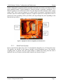
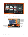
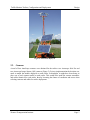


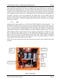
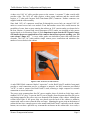


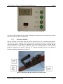


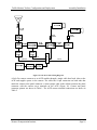
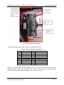
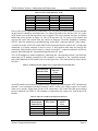
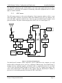
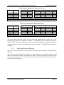

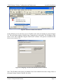

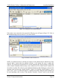
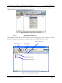


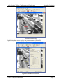

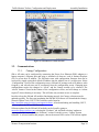

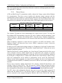
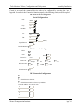


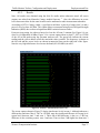

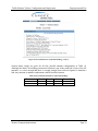
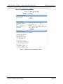
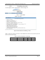
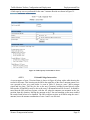

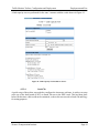

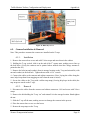

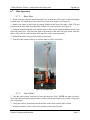

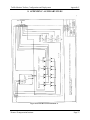
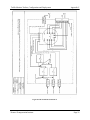


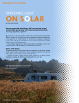


![Télécharger Pdf [3 890 Ko] - Groupement pour l`Amélioration de l](http://vs1.manualzilla.com/store/data/006453454_1-f2b09e64f4cbbe4159e9eda196b950b9-150x150.png)