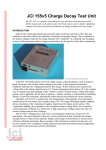
Download USER MANUAL: JCI 134 Base Unit for JCI 131
Transcript
OOO
OOO
OOOOO
OOOOO
OOOOO
OOOOOOOOOO
OOO OOOO
OOOO
OOO OOOO
OOO OOOO
OOOO
OOO
OOOOOOOOOO
OOO OOO
OOOOOO
OOO OOO
OOOO
OOO
OOO
OOOOOO
OOOOOO
OOO
OOO
OOO
OOOOOOO
OOOOOOO
John Chubb
Instrumentation
Unit 30, Lansdown Industrial Estate, Gloucester Road,
Cheltenham, GL51 8PL, UK. Tel: +44 (0)1242 573347
Fax: +44 (0)1242 251388 email: [email protected]
________________________________________________________________________________________
USER MANUAL: JCI 134 Base Unit
for JCI 131 Electrostatic Fieldmeter
UM134 - Issue 1: July, 2004
Contents:
1. Introduction
2. JCI 134 Specification features
3. Operational features
3.1 Basic features
3.2 Sensitivity range selection
3.3 Operational health facilities
4. Power supply requirements
5. Connections
6. Setting up
6.1 Basic set-up
6.2 Setting operatioanl facilities
6.3 Setting ambient field sensitivity
7. Operational health nonityoring
8. Safety and protection
9. Operation in flammable atmospheres
10. Operating environmental conditions
11. Applications
12. Data recording and processing
References
Figures
CE CONFORMANCE
John Chubb, proprietor of John Chubb Instrumentation of Unit 30, Lansdown Industrial Estate, Gloucester Road,
Cheltenham, GL5l 8PL, declares as designer and manufacturer, that the JCI 131 electrostatic fieldmeter conforms
to the requirements of the EC Directive on Electromagnetic Compatibility (EMC) 89/33/EEC to Standards EN
50081-1:1992 and EN 50082-1:1992. This instrument also conforms to the requirements of the Electrical
Equipment (Safety) Regulations 1994 (SDI. 1994/3260),
Signed for and on behalf of JCI:
John Chubb
Page - 1
USER MANUAL: JCI 134 Base Unit
providing mains or battery operation of JCI 131 fieldmeters
with display of fieldmeter reading and indication of
operational health status.
1. INTRODUCTION
JCI 131 fieldmeters may be operated in conjunction with a JCI 134 Base Unit to provide
mains or battery operation and display of electric field measurements and indication of
operational health status. The JCI 131 fieldmeter sensing head unit is shown in Figures 2 and
3.
The JCI 134 provides opportunity to use both a mains input power supply with a battery
connected at the same time for uninterruptible operation in the event of mains supply failure.
Connections are provided for two battery inputs so that recharged batteries can be connected
without interrupting operation. Power supply to the JCI 131 is 24V supplied as +12V and 12V. This supply voltage helps minimise resistive losses in the connecting cable. Operational
power is switched on with a key switch. This provides protection against accidental
interruption of operation.
The fieldmeter output signal is proportional to the observed electric field. Signal output is
2.0V for electric fields at the sensing aperture of 2, 20, 200 or 2000kV m-1. Fieldmeter
readings are displayed on a 3½ digit LCD on the JCI 134 as kV m-1. When used for
atmospheric electric field observations or as part of a Lightning Warning System [1] the JCI
131 is likely to be mounted at the top of a pole (for example as shown in Figure 4) – for
example a JCI 137. In this situation electric field values at the fieldmeter sensing aperture are
enhanced over the anbient atmospheric electric field value [2,3]. The JCI 134 Base Unit
provides the facilities to display the ambient atmospheric electric field and, optionally, the
electric field observed by the fieldmeter. The relationship between ambient and observed
electric field values depends upon mounting arrangements and influence of ground profile and
nearby structures. Provision is made to cover such variations by user adjustment of the
relationship.
2. JCI 134 SPECIFICATION FEATURES:
Power supply:
- Universal mains power supply (40W). IEC input connector in
backplate fused 3A.
- external 12V battery supply via either of two 2.1mm d.c. input
connectors.
- 24V supply output to JCI 131 fieldmeter.
Power supply on/off: Key lock operated main power supply on/off switch on back cover
Controls:
- 2 key switches to select auto-ranging (pressed together) or to select a
range and to change ranges up and down. ‘Up’ key flashes if over-range.
- key switch to display fieldmeter health source signal (100% nominal)
- key switch to display operational output signal (100% nominal)
- toggle key selection of operational health on/off
- push switch in back cover to select fieldmeter electric field values as
opposed to interpreted ambient atmospheric electric field
- pot to adjust FM sensitivity for display as ambient atmospheric fields
Page - 2
- pot for fieldmeter zero adjustment
JCI 131 connection: 19w connector (Pattern 105 AB05 210014-19SN00) in end cover to take
cable to JCI 131 fieldmeter
Signal outputs:
- 25w D type connector for direct connection to all input and output
signals on 19w cable together with operational and alarm status signals.
These may be linked to external signal display and datalogging system.
Earthing:
Earth bonding terminal
Displays:
- 3½ digit LCD presentation of electric field
- key operated options to show levels of operational health signals.
- LO BATT indication on LCD
- LED indicator for mains operation
- LED indicator for external battery operation
- LED indicators for health of fieldmeter
Mechanical:
220x170 65mm deep metal enclosure, 2kg.
3. OPERATIONAL FEATURES
3.1 Basic feastures
The JCI 134 Base Unit is housed in a 220 x 170 x 65mm deep metal enclosure. Cable
connection to the JCI 131 is made via the 19w connector at the top end cover. There is also
there a 25w D type connector for diagnostic and data recording. The back end cover houses a
fused IEC mains supply connector, two 2.1mm d.c. power connectors for 12V battery
operation, a power supply ON/OFF switch and fuse and a number of adjustment facilities.
Figure 1 shows the layout of the top panel of the JCI 134. The small LEDs along the lower
edge of the top cover indicate power supplies actively available. A separate LED shows when
the JCI 131 is powered on by clockwise rotation of the key operated power supply switch at
the right hand end of the back cover.
When the JCI 131 fieldmeter is operating the electric field readings will be shown on the
LCD. This will be the value interpreted by the setting of the range and sensitivity controls in
the back cover. The actual electric field observed by the fieldmeter may be shown at any time
by pressing the push button in the bottom cover. This push button is used in conjunction with
sensitivity controls to adjust the normally displayed reading to be that for the fieldmeter or the
ambient atmospheric eletcric field value. The adjustement procedure is described in Section
6.3.
3.2 Sensitivity range selection
The default arrangement is for the JCI 131 fieldmeter to operate in an autoranging mode. A
step down of sensitivity is made at a signal level close to the full scale output of 2.0V, and a
step up in sensitivity at an output level around 0.15V.
If it is desired to access and hold a particular range then when a ‘Range control’ up or down
key is pressed the range will be incremented or decremented a step. To return to the auto-range
mode both keys are pressed together.
3.3 Operational health facilities
Page - 3
If the operational health facility is fitted to the JCI 131 fieldmeter head unit [1] then LEDs
on the top cover indicate the operastional health status. The operastional health may be toggled
on and off using the key switch, and an LED indicates while the facility is activated.
If the operational health drive signal and/or the observed health signal are below 90% of
the values to be expected then the amber LEDs in the appropriate key switches are illuminated.
If these LED keys are pressed at any time the LCD will show the percentage of satisfactory
level for these two components.
If the operational health facility is not fitted to the JCI 131 fieldmeter then none of the
operational health control switches are active and none of the associated LEDs illuminate.
4. POWER SUPPLY REQUIREMENTS
The JCI 131 fieldmeter can be operated from a power supply of 12-36V with a capability of
about 1A capability. Running current is about 400mA at 12V. The wide range of supply input
makes it easier to work with long cables and less well defined supply sources. With long cables
the voltage drop along the lines needs to be noted and it will be wiser to expect to operate from
a voltage source supply nearer to 36V rather than 12V. The regulated power supply voltages
needed for instrument operation are created from a 9-36V input d.c./d.c. converter inside the
fieldmeter head unit.
5. CONNECTIONS
Power supply and signal connections between the JCI 134 Base Unit and the JCI 131
fieldmeter are made via sealed 19w Mil connectors. The following table lists both the
connections at each 19w socket and the connections available via the 25w D type diagnostic
connector. (Signal line identities are also listed for operation of an enhanced version Base Unit
which, with the radio circuit board fitted into the fieldmeter, makes a JCI 503 Lightning
Warning System. These lines are not connected in the JCI 134 Base Unit).
Cable feature
Cable sheath & case
0V
+12V power
-12V power
Fieldmeter 0V
Fieldmeter signal
Range bit 0 (field x10)
Range bit 1 (field x100)
Zero adjust
Field overrange
Noise signal
Noise x10
Health inhibit
Field health drive
Noise health
Impulse signal
Impulse x10
Impulse health
Field health signal
Field DVM
19w cable connector
A green/yellow
B black
C red & yellow/blue
D blue & blue/white
E green
F white
G yellow
H brown
J violet
K orange
L pink
M turquoise
N grey
P red/blue
U green/red
V yellow/red
R white/red
S red/black
T red/brown
Field range +1
Field range -1
25w D type diagnostic socket
1
2
3
4
5
6
7
8
9
10
11
12
13
14
15
16
17
18
19
20
21
Page - 4
Noise DVM (dB)
Lightning pulse
Amber lightning alert
Red lightning alert
22
23
24
25
Fieldmeter operation will be satisfactory with cable lengths to at least 100m. The cable
shielding braid should be earth bonded at both ends. For good quality analogue signal
observations over long cable lengths it is wise to use a unity gain differential buffer amplifier
between the fieldmeter 0V and signal lines at the signal processing end.
The signals indicating and controlling the sensitivity range and external zero adjustment are
relatve to instrument 0V - the black lead on connection B.
Cable: DEF Stan 61-12 Part 4: 7/0.2 PVC insulated, overall braid screened, PVC sheathed type
7-2-20C. Resistance: 0.08 ohms per metre each core. Capacitance: 160pF per meter per
conductor to sheath.
Connectors: Sealed 19w cable connectors (Pattern 105). Free plug: AB05 602714-19PN00
Socket: AB05 210014-19SN00
6. SETTING UP
6.1 Basic set up
Connect the cable from the JCI 131 sensing head to the 19w connector on the JCI 134 Base
Unit. Connect either a mains power supply or a 12V battery (positive center connection) to
either 2.1 d.c. power sockets in back cover. The appropriate LED at the bottom edge of the top
cover should illuminate. Switch on using key-lock rotary switch at right hand side of back
plate. The power on’ LED should illuminate amnd the LCD should show a reading. If the JCI
131 is connected it should start operting and if a piece of rubbed plastic is brought into the
vicinity of the fieldmeter sensing aperture the LCD should show an appropriately increasing
reading.
For checking the zero reading of the fieldmeter a suitable Zero Check Chamber (for
example a JCI 152) is placed over the sensing end of the fieldmeter. With the push button to
select the direct fieldmeter reading depressed the zero setting potentiometer in the back cover
is adjusted for a zero reading on the LCD. A reading within 1-2V m-1 should be achieved.
6.2 Setting operational facilities
The basic sensitivity of the JCI 131 as a voltage probe is close to 10kV m-1 for a local
potentila of 1kV. If this is mounted at the top of a, say, 2m pole then a reading of 10kV m-1
will correspond to an ambient local field of 0.5kV m-1 [4]. If the operational health shield is
fitted that the fieldmeter readings will be about 50% of the aove figure – around 5kV m-1 for an
ambient field of 0.5 kV m-1.
The actual local voltage sensitivity of the fieldmeter sensor, at its mounted position, can be
established (or checked) by operating the JCI 131 and JCI 134 isolated from ground and
applying a calibration voltage to the assembly. With the ‘Check sensor electric field’ pressed
(so the LCD shows directly the actual fieldmeter reading) apply a measured voltage between
external earth and the earthing terminal of the JCI 134. Note the change in LCD reading
between applying this voltage and earthing the assembly. The actual ambient atmospheric field
corresponding to this voltage change is then simply the voltage change divided by the height of
the pole in metres.
6.3 Setting ambient electric field sensitivity
The ‘Check sensor electric field’ push button in the back cover provides opportunity to
switch the LCD reading between fieldmeter readings and interpreted ambient electric field
values. The local voltage sensitivity of the JCI 131 fieldmeter, and the operational health shield
Page - 5
if fitted, are established as above. The interpreted value of ambient atmospheric electric field
are obtained with knowledge of the pole height. The display may be adjusted to give
appropriate values of ambient electric field using the potentiometer in the back plate. Matching
between fieldmeter and ambient values is achieved using the ‘Check sensor electric field’ push
button.
If the JCI 131 needed to be mounted at a location where there may be some shielding of
atmospheric electric fields by nearby structure or is mounted on a building then the absolute
level of readings may be estanblished in clear blue sky conditions by comaping readings to
ambient electric field values established at the same time with a pole mounted fieldmeter
readings on a large flat area of ground. The clear blue sky ambient eletcric field will be about
100V m-1. A large flat area should give clearances of a few hundred metres to any trees or
structures.
7. OPERATIONAL HEALTH MONITORING
To give confidence in operational performance in long term continuous observations an
operational health system has been developed for the JCI 131 fieldmeter. This is available as
an optional extra facility.
Operational health monitoring was originally developed as part of the JCI 501 Lightning
Warning System [1]. In that system the whole fieldmeter sensing head unit was modulated
with a low frequency square wave alternating signal of some 50V peak to peak amplitude.
This modulated the observed electric field signal and the amplitude of modulation was
compared to the level expected. The present facility involves mounting an additional shield
around the casing of the JCI 131 fieldmeter sensing head, , and modulating the shield with a
sinewave voltage at half the electric field modulation frequency. The body of the fieldmeter
remains at earth potential. Separate phase sensitive detection enables the modulated signal
from the shield to be selectively extracted for comparison to the level expected. There is no
influence on normal ambient field measurements The voltage swing of the shield is set
appropriate to the fieldmeter operating range of sensitivity, and may be up to 600V p-p for the
low sensitivity range.
The operational health status is displayed on the JCI 134 is two ways: first, the level of the
operational drive signal (‘Health drive’) is compared to its target value (1.0V) and if it is less
than 90% of this then the key amber LED is illuminated. Second, if the fieldmeter health signal
is less than 90% of the drive signal then the ‘fieldmeter health’ key amber LED is illuminated.
At any time either or these keys may be pressed and the LCD will then show the status of each
of these operational heath signals as a % of expected value.
If the operational healthe facility is not included in the JCI 131 then no LEDs will be
illuminated when the ‘Health on/off’ key is pressed. Also when either the and the LCD will
display only 0.0 when the ‘fieldneter health OK’ key is pressed.
8. SAFETY AND PROTECTION
It is important to avoid any articles, or fingers, to enter the sensing aperture of the JCI 131
fieldmeter - particularly when the chopper assembly is rotating. It is aslo important not to drop
or hit the fieldmeter sensing head unit as this could damage the alumina sleeve insulator that
mounts the rotor assembly on the motor shaft.
9. OPERATION IN FLAMMABLE ATMOSPHERES
The JCI 131 is not Certified as suitable for use in areas where flammable atmospheres are,
or may be, present.
10. OPERATING ENVIRONMENTAL CONDITIONS
Page - 6
No specific tests have been made to find the allowable operating environmental conditions.
An operating range is suggested of 0-30C and 20-100%RH including direct rain precipitation
into the sensing aperture. There is no reason why the JCI 131 will not operate satisfactorily
below 0C purely in terms of ambient temperature If there is a prospect of snow or freezing
rain or of sub-zero temperatures after snow precipitation then it is recommended that the
Sensor Unit is kept in continuous operation, and so kept warm, to avoid clogging operation of
the rotating chopper assembly.
11. APPLICATIONS
Applications for the JCI 131 fieldmeter are described and discussed in the instrument user
manual.
12. DATA RECORDING AND PROCESSING
The 25w D tryope connector provides access to all fieldmeter and analysed signals – as
idenbtified in Section 5 above. These signals may be displayed and or recorded according to
user interests. One approach that may be useful for computer based data recording, which is
Windows compatible (up to XP), is use of a Picoscope digital storage oscilloscope facility
(www.picotech.com).
REFERENCES
[1] J. N. Chubb, J. Harbour “A system for the advance warning of the risk of lightning” Proc
ESA Annual Meeting 2000. Brock University, Niagara Falls, Ontario June 18-21, 2000
[2] J. M. Van der Weerd "Electrostatic charge generation during washing of tanks with water
sprays, II Measurements and interpretation" Static Electrification Conference, London, 1971
IoP p 158
[3] J. N. Chubb, G. J. Butterworth, "Instrumentation and techniques for monitoring and
assessing electrostatic ignition hazards" Electrostatics 1979 Inst Phys Confr Series No 48
1979 p 85
[4] JCI Website: www.jci.co.uk (for example www.jci.co.uk/Measurements/AtmosEfield.html and
www.jci.co.uk/Electrostatics/Wshop-00.html)
Page - 7
Figure 1: Top cover layout for JCI 134 Base Unit
Page - 8
Figure 2: General view of JCI 131 Electrostatic Fieldmeter
Figure 3:Internal features of JCI 131
Page - 9
Figure 4: JCI 131 fieldmeter mounted for measurement of atmospheric electric fields
Page - 10


