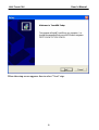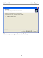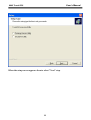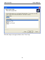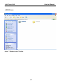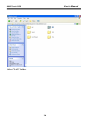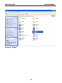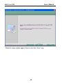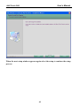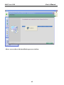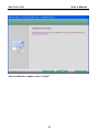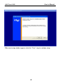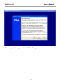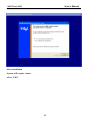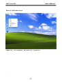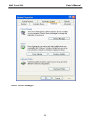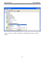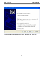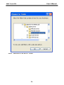
1
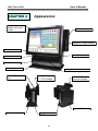
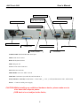
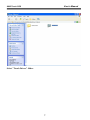
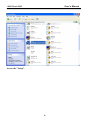
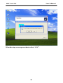
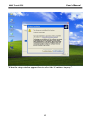
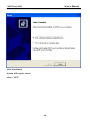
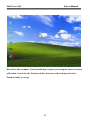
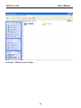
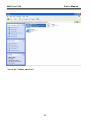
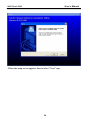
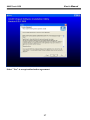
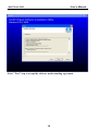
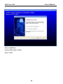
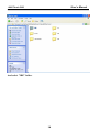
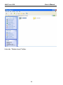
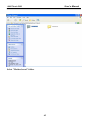
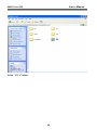
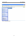
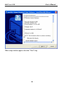
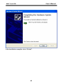
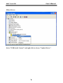
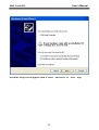
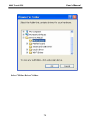
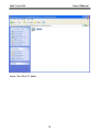
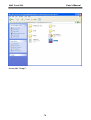
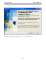
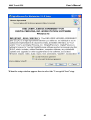
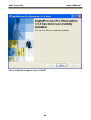
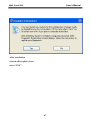
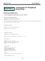
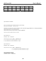
11/06/2007 JARLTECH ISO 9001 Certified Lead with technology Win customers with service Touch POS System SERIES 8805 Verson:1.0 OPERATION MANUAL User’s Manual 8805 Touch POS Table of Contents: Chapter 1 Introduction ..................................................................................................2 Chapter 2 Appearance ...................................................................................................4 Chapter 3 Installation ....................................................................................................6 Chapter 4 Commands for Peripheral Controlling .....................................................88 Chapter 5 Hardware Configuration .......................................................................... .91 Chapter 6 Hardware Specification ............................................................................. 105 Appendix – LAN Controller........................................................................................ 117 1 User’s Manual 8805 Touch POS CHAPTER 1 Introduction Preview Jarltech is defining the New Age of POS with its integrated TouchPOS. The 8805 is designed on NB base with Intel Celeron M processor 1 GHz or above, Two slot of DDR SODIMM memory max up to 2GB; 15” TFT-LCD with resistive touch screen; built-in VGA, LAN chip, Internal IDE Hard disk (20GB or above). Thus designation helps user easy and comfortable to handle. Its multi-functional capability makes it suitable for software developments under Windows XP, XP Embedded, XP professional for Embedded, WIN 2000 professional Embedded, WIN NT 4.0, Linux, Redhat 7.2, WIN98, ME. The 8805’s functionality extends far beyond the standard setup. 8805 can be adapted for a variety of uses with the addition of any of the following options: Magnetic Card Reader,Smart Card Reader, 20 x 2 VFD customer display, the second 10.4" TFT LCD display, cashdrawer, i-Button , Fingerprint ,Wi-Fi ,RFID , USB Key-locker or USB devices (all available upon request). The brand new Touch POS 8805 has been designed with all advantages from JARLTECH POS series, but less cost to customer with its interactive transaction, RFID and smart card reader design provides multiple clerk access and customer database management, suitable and superior for super-market, hotel, convenience store, restaurants and any organization or store that needs point of service. Notes: Must to adjust display setting in BIOS first. Advanced Chipset Features On-Chip VGA Setting Boot Display [CRT+LCD] Panel Type [1024x768 24Bit 1CH] 2 User’s Manual 8805 Touch POS FCC This device complies with part 15 of the FCC rules. Operation is subject to the following two conditions: (1) This device may not cause harmful interference (2) This device must accept any interference received, including interference that may cause undesired operation. CE MARK This device complies with the requirements of the EEC directive 89/336/EEC with regard to “Electromagnetic compatibility” and 73/23/EEC “Low Voltage Directive”. CAUTION ON LITHIUM BATTERIES There is a danger of explosion if the battery is replaced incorrectly. Replace only with the same or equivalent type recommended by the manufacturer. Discard used batteries according to the manufacturer’s instructions. LEGISLATION AND WEEE SYMBOL 2002/96/EC Waste Electrical and Electronic Equipment Directive on the treatment, collection, recycling and disposal of electric and electronic devices and their components. 3 User’s Manual 8805 Touch POS CHAPTER 2 Appearance 15" TFT color display with touch screen Smart Card Reader Magnetic Stripe Reader Power Led i-Button HDD Led USB Locker RFID Wi-Fi IEEE 802.11 b/g Fingerprint identification The second 10.4" TFT LCD Display 20X2 VFD Customer Display I/O Port Slim Type CD-ROM Speaker 2W*2 4 User’s Manual 8805 Touch POS VGA Port K/B Port S/W 1&2 (Cash Draw controll) Power Fan COM1 COM2 USB Port *2 AC Power LAN Port Printer Port Audio In/Out Mouse Port CD1/CD2 COM1/COM2: Standard DB9 PIN Serial port Mouse: PS2 mouse socket K/B: PS2 Keyboard socket USB: USB port X 2 VGA: 15 Pins VGA Connector LAN: Ethernet connector Multi-Media: Line Out / MIC / Line-In CD1/CD2: Cash Draw 1(beside S/W) and Cash Draw 2 S/W(Cash Draw controll): Switch button – S/W1 S/W2; ↓ = ON, ↑= OFF (Default S/W1=OFF , S/W2=OFF) Power: Connect to ATX power supply CAUTION:While installing any additional hardware device, please make sure to shut down the computer power. (USB device is not subject to the limits.) 5 User’s Manual 8805 Touch POS CHAPTER 3 Driver Installation Touch Drivers Insert CD Rom and select "Driver & Manual" folder. 6 User’s Manual 8805 Touch POS Select "Touch Driver" folder. 7 User’s Manual 8805 Touch POS Access the "Setup". 8 User’s Manual 8805 Touch POS When the setup screen appears then to select "Next" step. 9 User’s Manual 8805 Touch POS When the setup screen appears then to select "Next" step. 10 User’s Manual 8805 Touch POS When the setup screen appears then to select "Next" step. 11 User’s Manual 8805 Touch POS When the setup screen appears then to select "Next" step. 12 User’s Manual 8805 Touch POS When the setup screen appears then to select "Next" step. 13 User’s Manual 8805 Touch POS When the setup screen appears then to select “ YES”. 14 User’s Manual 8805 Touch POS When the setup window appear then to select the “Continue Anyway”. 15 User’s Manual 8805 Touch POS After installation System will require reboot select “ YES” 16 User’s Manual 8805 Touch POS When first time complete Touch installation, require processing the cursor accuracy calibration, Search for the Touchset utility shortcut on the desktop and select Touchset utility to set up. 17 User’s Manual 8805 Touch POS When configuration window appear, select the language which you desire. (As above selected picture explanation) 18 User’s Manual 8805 Touch POS Then to select calibration function and select numbers of calibration point first (above picture shows select by 4 numbers) next to click on calibrate button. 19 User’s Manual 8805 Touch POS The screen will shows as above picture, use the Touch pen to point on dot to align the cursor, if the actual alignment has too much difference then the system will skip back to previous screen and require calibration once again. 20 User’s Manual 8805 Touch POS The numbers of the calibration point shows on the screen will depend on the number you have set previously, after complete system will skip back to desktop (if the cursor still not accurate please repeat the calibration again). 21 User’s Manual 8805 Touch POS IDE Drivers Insert CD Rom and select "Driver & Manual" file folder. 22 User’s Manual 8805 Touch POS Select the "Mother board" folder. 23 User’s Manual 8805 Touch POS And select "IDE" folder. 24 User’s Manual 8805 Touch POS Access the "infinst_autol.exe". 25 User’s Manual 8805 Touch POS When the setup screen appears then to select "Next" step. 26 User’s Manual 8805 Touch POS Select "Yes" to accept authorization agreement. 27 User’s Manual 8805 Touch POS Select "Next" step to accept the software understanding agreement. 28 User’s Manual 8805 Touch POS After installation System will require reboot select “YES” 29 User’s Manual 8805 Touch POS And select "IDE" folder. 30 User’s Manual 8805 Touch POS Select the "Mother board" folder. 31 User’s Manual 8805 Touch POS Select "Sound" folder. 32 User’s Manual 8805 Touch POS Access the "Setup". 33 User’s Manual 8805 Touch POS When the setup screen appears click the "Next" step. 34 User’s Manual 8805 Touch POS Above screen shows the setup process. 35 User’s Manual 8805 Touch POS After installation System will require reboot select “YES” 36 User’s Manual 8805 Touch POS LAN Drivers Select "Mother board" folder. 37 User’s Manual 8805 Touch POS Select "LAN" folder. 38 User’s Manual 8805 Touch POS Access the "Setup". 39 User’s Manual 8805 Touch POS When the setup window appear then to select the "Next" step. 40 User’s Manual 8805 Touch POS When the next setup window appears again select the setup to continue the setup process. 41 User’s Manual 8805 Touch POS Above screen shows the installation process window. 42 User’s Manual 8805 Touch POS After installation complete select “Finish”. 43 User’s Manual 8805 Touch POS VGA Drivers Insert CD Rom and select "Driver & Manual" file folder. 44 User’s Manual 8805 Touch POS Select "Mother board" folder. 45 User’s Manual 8805 Touch POS Select "VGA" folder. 46 User’s Manual 8805 Touch POS Access "win2k_xp141950.exe". 47 User’s Manual 8805 Touch POS When setup window appear select the "Next" step. 48 User’s Manual 8805 Touch POS When next setup window appear select the "Next" step to continue setup. 49 User’s Manual 8805 Touch POS When setup window appear select the "Next" step. 50 User’s Manual 8805 Touch POS After installation System will require reboot select “YES” 51 User’s Manual 8805 Touch POS Smart Card Reader Driver Right click "My Computer" and select the "Properties". " 52 User’s Manual 8805 Touch POS Select "Device Manager". 53 User’s Manual 8805 Touch POS Select "USB PC/SC Smart Card Reader" and right click to choose "Update Driver". 54 User’s Manual 8805 Touch POS When the setup screen appears then to select "Advanced" & "Next" step. 55 User’s Manual 8805 Touch POS Select "Smartcard USB Driver" folder. 56 User’s Manual 8805 Touch POS When next setup window appear select the "Next" step to continue setup. 57 User’s Manual 8805 Touch POS When next setup window appear select the "Continue Anyway" step to continue setup. 58 User’s Manual 8805 Touch POS Above screen shows the installation process window. 59 User’s Manual 8805 Touch POS After installation complete select “Finish”. 60 User’s Manual 8805 Touch POS Wi-Fi Driver Right click "My Computer" and select the "Properties". 61 User’s Manual 8805 Touch POS Select "Device Manager". 62 User’s Manual 8805 Touch POS Select "USB2.0 WLAN" and right click to choose "Update Driver". 63 User’s Manual 8805 Touch POS When the setup screen appears then to select "Advanced" & "Next" step. 64 User’s Manual 8805 Touch POS Select Wi-Fi Driver folder. 65 User’s Manual 8805 Touch POS When next setup window appear select the "Next" step to continue setup. 66 User’s Manual 8805 Touch POS When next setup window appear select the "Continue Anyway" step to continue setup. 67 User’s Manual 8805 Touch POS Above screen shows the installation process window. 68 User’s Manual 8805 Touch POS After installation complete select “Finish”. 69 User’s Manual 8805 Touch POS Mifare Driver Select "USB-Serial Control" and right click to choose "Update Driver". 70 User’s Manual 8805 Touch POS When the setup screen appears then to select "Advanced" & "Next" step. 71 User’s Manual 8805 Touch POS Select "Mifare Driver" folder. 72 User’s Manual 8805 Touch POS When next setup window appear select the "Next" step to continue setup. 73 User’s Manual 8805 Touch POS When next setup window appear select the "Continue Anyway" step to continue setup. 74 User’s Manual 8805 Touch POS Above screen shows the installation process window. 75 User’s Manual 8805 Touch POS After installation complete select “Finish”. 76 User’s Manual 8805 Touch POS Fingerprinter Driver Select "Fingerprinter" folder. 77 User’s Manual 8805 Touch POS Select "Pro Ws 3.5" folder. 78 User’s Manual 8805 Touch POS Access the "Setup". 79 User’s Manual 8805 Touch POS When the setup window appear then to select the "Next" step. 80 User’s Manual 8805 Touch POS When the setup window appear then to select the "I accept & Next" step. 81 User’s Manual 8805 Touch POS When the setup window appear then to select the "Next" step. 82 User’s Manual 8805 Touch POS When the setup window appear then to select the "Next" step. 83 User’s Manual 8805 Touch POS When the setup window appear then to select the "Next" step. 84 User’s Manual 8805 Touch POS Above screen shows the installation process window. 85 User’s Manual 8805 Touch POS After installation complete select “Finish”. 86 User’s Manual 8805 Touch POS After installation System will require reboot select “YES” . 87 User’s Manual 8805 Touch POS CHAPTER 4 Commands for Peripheral Controlling RS232 Protocol: 9600bps-N-8-1 Notice: Peripheral Control must be set up "COM3" Follow the Jarltech standard command: Send : <ESC> <Command code> <Length> <Data> Response: <ESC> <Status code><length><data> Note: 8805 controller return a beep after power on, delay about 3 sec then urn on the Main TFT Backlight, return another beep and then start to receive the RS232 commands. Read products Model Name Command : <ESC><00h> Length & Data don’t need. Response : <ESC><00h><07h><JP-8805> Read Products Version info Command : <ESC><01h> Length & Data don’t need. Response: <ESC><01h> <Length depends on data ><8805 POS ……… V1.0 ….> Beeps command: Command : <ESC><22h> <01h><data> <Data> = 00h ~ FFh , means how many beeps. Response: <ESC><22h><01h><data> Sound command: Command : <ESC><24h> <02h><m><n> m: tempo (ASCII DEC 1~255) n: Frequency (ASCII DEC 1~255) Response: <ESC><24h><02h><m><n> Example: <ESC><24h><02h><dec 2><dec 191> for play sound “Do“ Example Sound frequency Table: 88 User’s Manual 8805 Touch POS Do Re Mi Fa So La Si G- : 255 A- : 227 B- : 202 C : 191 D : 170 E : 151 F : 143 G : 127 A : 113 B : 101 C+: 95 D+: 85 E+: 75 F+: 71 G+: 63 A+: 57 B+: 50 Open Cash Drawer Command : Before send command, please confirm the S/W1 for provides voltage: S/W1=OFF: 24V (default) S/W1=ON: 12V The S/W2 is for setting auto response cash drawer sensor status after trigger cash drawer, or if someone manually to open the cash drawer or close the cash drawer Then controller will auto response status to software application. . S/W2=OFF: disable (default) S/W2=ON: Enable Open Cash Drawer 1 Command : <ESC> + 34h (dec 52) When S/W2=ON response: <ESC> + 34h (dec 52) + N N = “A” (41h, dec 65) , means Cash Drawer 1 is close. N = “B” (42h, dec 66) , means Cash Drawer 1 is open. Open Cash Drawer 2 Command : <ESC> + 35h (dec 53) When S/W2=ON response: <ESC> + 35h (dec 53) + N N = “A” (41h, dec 65), means Cash Drawer 2 is close. N = “B” (42h, dec 66), means Cash Drawer 2 is open. Detect Cash Drawer 1 Sensor Command : <ESC> + 3Ah (dec 58) 89 User’s Manual 8805 Touch POS Response: <ESC> + 34h (dec 52) + N N = “A” (41h, dec 65) , means Cash Drawer 1 is close. N = “B” (42h, dec 66) , means Cash Drawer 1 is open. Detect Cash Drawer 2 Sensor Command : <ESC> + 3Bh (dec 59) Response: <ESC> + 35h (dec 53) + N N = “A” (41h, dec 65), means Cash Drawer 2 is close. N = “B” (42h, dec 66), means Cash Drawer 2 is open. Turn on the main TFT LCD backlight Command : <ESC> + 38h (dec 56) Turn off the main TFT LCD backlight Command : <ESC> + 39h (dec 57) Support Epson command to open the cash drawer: 1. 2. [ESC] p m t1 t2 DLE DC4 n m t 90 User’s Manual 8805 Touch POS CHAPTER 5 Hardware Configuration 5-1. COMPONENT LOCATIONS Placement Top View 170mm 170mm (Dimensions: +/- 1mm) 91 User’s Manual 8805 Touch POS Bottom View 92 User’s Manual 8805 Touch POS Jumper Settings To ensure correct system configuration, the following section describes how to set the jumpers to enable/disable or change functions. For jumper descriptions, please refer to the table below. Location Function JP1 COM1 Signal / Power Selection JP2 COM2 Signal / Power Selection JP3 COM3 Signal / Power Selection JP4 COM4 Signal / Power Selection JP5 COM5 Signal / Power Selection JP6 COM6 Signal / Power Selection JP7 LPT1 Signal / Power Selection JP8 JP9 CFD1 Master / Slave Selection Clear CMOS Selection JP10 LVDS Panel Power Selection Table 2-1. Jumper Descriptions JP1 - COM1 Signal/Power Selection (Pitch: 2.54mm): Jumper 1 9 2 1 10 2 Setting Function 1-3 Short Pin 1 of COM1 = +12V 3-5 Short Pin 1 of COM1 = +5V 5-7 Short Pin 1 of COM1 = +5V 7-9 Short Pin 1 of COM1 = DCD 2-4 Short Pin 9 of COM1 = +12V 4-6 Short Pin 9 of COM1 = +5V 6-8 Short Pin 9 of COM1 = +5V 8-10 Short Pin 9 of COM1 = RI Table 2-2. JP1 - COM1 Signal/Power Selection Settings JP2 - COM2 Signal/Power Selection (Pitch: 2.54mm): Jumper 1 9 2 1 10 2 Setting Function 1-3 Short Pin 1 of COM2 = +12V 3-5 Short Pin 1 of COM2 = +5V 5-7 Short Pin 1 of COM2 = +5V 7-9 Short Pin 1 of COM2 = DCD@RS232, TX+@RS422, RTX+@RS485 2-4 Short Pin 8 of COM1 = +12V 4-6 Short Pin 8 of COM1 = +5V 6-8 Short Pin 8 of COM1 = +5V 8-10 Short Pin 8 of COM1 = RI Table 2-3. JP1 - COM2 Signal/Power Selection Settings 93 User’s Manual 8805 Touch POS JPx - COMx Signal/Power Selection (x = 3, 4, 5, 6 - Pitch: 2.54mm): Jumper 1 9 2 Setting 1 10 2 Function 1-3 Short Pin 1 of COMx = +12V 3-5 Short Pin 1 of COMx = +5V 5-7 Short Pin 1 of COMx = +5V 7-9 Short Pin 1 of COMx = DCD 2-4 Short Pin 8 of COMx = +12V 4-6 Short Pin 8 of COMx = +5V 6-8 Short Pin 8 of COMx = +5V 8-10 Short Pin 8 of COMx = RI Table 2-4. JP1 - COM3-6 Signal/Power Selection Settings JP7 - LPT1 Signal/Power Selection (Pitch: 2.54mm): Jumper 1 2 Setting 1 2 9 10 3 Function 1-2 Short Pin 4 of LPT1 = ERR# 1-3 Short Pin 4 of LPT1 = +5V 4-6 Short Pin 6 of LPT1 = +5V 5-6 Short Pin 6 of LPT1 = INIT# 7-8 Short Pin 8 of LPT1 = SLIN# 7-9 Short Pin 8 of LPT1 = +5V Table 2-5. JP1 - LPT1 Signal/Power Selection CF Master/Slave Selector (JP8: 3-pin 2.54mm pitch header): Function JP1 Master Slave (Default) 1-2 Short 2-3 Short Table 2-6. CF Master/Slave Setting Clear CMOS setting (JP9: 2-pin 2.54mm pitch header): Function JP2 Normal (Default) Clear CMOS Open Short Table 2-7. Clear CMOS Setting 94 1 2 User’s Manual 8805 Touch POS Panel Power Selector (JP10: 3-pin 2.54mm pitch header): Function JP3 + 3.3 V (Default) +5V 1-2 Short 2-3 Short Table 2-8. Panel Power Setting Connector Pin Definitions For Main Board connector and header descriptions, please refer to the table below. Connector Function ATX1 ATX Power Connector CFD1 CN1 Compact Flash type I/II Connector IrDA Pin Header CN2 CN3 CN6 Digital Input / Digital Output Pin Header SM Bus Wafer Left Audio AMP Output Wafer CN7 LVDS Backlight Inverter Wafer CN8 COM2 COM3 Right Audio AMP Output Wafer RS-232 / 422 / 485 Port-2 Box Header RS-232 Port-3 Box Header COM4 RS-232 Port-4 Box Header COM5 COM6 DIMM1 RS-232 Port-5 Box Header RS-232 Port-6 Box Header Primary DDR SO-DIMM Socket DIMM2 Secondary DDR SO-DIMM Socket FAN1 FAN 1 Connector FAN2 FAN3 FAN 2 Connector FAN 3 Connector FDD1 Slim Type Floppy Connector FP1 Power LED Pin Header FP2 IDE1 IDE2 Front Panel Pin Header Primary 44-pin IDE Box Header Secondary 40-pin IDE Box Header KB1 Internal PS/2 Keyboard Wafer LVDS1 LVDS2 MPCI1 Channel 1 LVDS Connector Channel 2 LVDS Connector Mini-PCI Socket MS1 Internal PS/2 Mouse Wafer SW1 USB1 USB2 External PS/2 KB/MS Switch USB Port-2&3 Box Header USB Port-4&5 Box Header Table 2-9. Main Board Connector and Header Descriptions 95 User’s Manual 8805 Touch POS ATX Power Connector (ATX1: 10x2 pin female): PIN SIGNAL PIN SIGNAL 1 2 3 4 5 6 7 8 9 10 +3.3V +3.3V Ground +5V Ground +5V Ground PW-OK 5VSB +12V 11 12 13 14 15 16 17 18 19 20 +3.3V -12V Ground PS-ON Ground Ground Ground -5V +5V +5V Table 2-10. ATX Power Connector pin definition CompactFlash slot (CFD1): PIN SIGNAL PIN SIGNAL 1 3 5 7 9 11 13 15 17 19 21 23 25 27 29 31 33 35 37 39 41 43 45 47 49 GND D4 D6 CS0# ATASEL# A8 VCC A5 A3 A1 D0 D2 CD2 D11 D13 D15 VS1 IOWR# INTRQ CSEL# RESSET# INPACK# DASP# D8 D10 2 4 6 8 10 12 14 16 18 20 22 24 26 28 30 32 34 36 38 40 42 44 46 48 50 D3 D5 D7 A10 A9 A7 A6 A4 A2 A0 D1 IOCS16# CD1 D12 D14 CS1# IORD# WE# VCC VS2# IORDY REG# PDIAG# D9 GND Table 2-11. CompactFlash Slot pin definition 96 User’s Manual 8805 Touch POS IrDA Pin Header (CN1: 5x2-pin header 2.54mm pitch): 1 Pin Signal Name 1 +5V 2 3 4 5 NC IRRX GND IRTX 5 Table 2-12. Digital I/O Pin Header pin definition Digital I/O Pin Header (CN2: 5x2-pin header 2.54mm pitch): PIN SIGNAL PIN SIGNAL 1 3 5 7 9 DO0 DO1 DO2 DO3 +5V 2 4 6 8 10 DI0 DI1 DI2 DI3 GND 1 2 3 4 5 6 7 8 9 10 Table 2-13. Digital I/O Pin Header pin definition SMBus Wafer (CN3: 2x1-pin Wafer 2.0mm pitch): Pin Status 1 2 SMDAT SMCLK Table 2-14. SMBus Header pin definition Left Audio AMP Output Wafer (CN6: 2x1-pin Wafer 2.5mm pitch): Pin Signal Name 1 2 Speaker+ Speaker- Table 2-15. Left Audio AMP Output Header pin definition LVDS Backlight Inverter (CN7: 7x1-pin Wafer 2.0mm pitch): Pin Signal Name 1 2 3 4 5 6 7 +12V +12V +5V GND GND Black Light Enable Back Light Control Table 2-16. LVDS Backlight Inverter Header pin definition 97 User’s Manual 8805 Touch POS Right Audio AMP Output Wafer (CN8: 2x1-pin Wafer 2.5mm pitch): Pin 1 2 Signal Name Speaker+ Speaker- Table 2-17. Right Audio AMP Output Header pin definition RS232/422/485 Serial Port Header (COM2: 5x2 box header 2.54mm pitch): Pin 1 2 3 1 2 4 5 9 10 6 7 8 9 10 Signal +5V / +12V / RS-232:DCD, Data carrier detect RS-422:TX+ RS-485:RTX+ Note:Selected by JP2 DSR, Data set ready RS-232:RXD, Receive data RS-422:RX+ RS-485:N/A RTS, Request to send RS-232:TXD, Transmit data RS-422:TXRS-485:RTXCTS, Clear to send RS-232:DTR, Data terminal ready RS-422:RXRS-485:N/A +5V / +12V / RI, Ring indicator Note:Selected by JP2 GND, ground NC Table 2-18. COM2 RS232/422/485 Serial Port Header pin definition RS232 Serial Port Header (COM3-6: 5x2 box header 2.54mm pitch): Pin 1 1 2 9 10 2 3 4 5 6 7 8 9 10 Signal +5V / +12V / DCD, Data carrier detect Note:Selected by JPx DSR, Data set ready RXD, Receive data RTS, Request to send TXD, Transmit data CTS, Clear to send DTR, Data terminal ready +5V / +12V / RI, Ring indicator Note:Selected by JPx GND, ground NC (x = 3, 4, 5, 6) Table 2-19. COM3-6 RS232 Serial Port Header pin definition 98 User’s Manual 8805 Touch POS Fan Connectors (Fan1-3: Wafer 2.54mm pitch): PIN SIGNAL 1 2 3 RPM +12V GDN 1 2 3 Table 2-20. Fan Connectors pin definition Power LED Pin Header 1 (FP1: 2x1-pin 2.54mm pitch): Pin 1 2 Status 1 Power LED + 2 Power LED Table 2-21. Power LED Pin Header 1 pin definition Front Panel Pin Header 2(FP2: 5x2-pin 2.54mm pitch): PIN SIGNAL PIN SIGNAL 1 3 5 7 9 HDD LED + HDD LED Reset Swatch Reset Swatch + NC 2 4 6 8 10 Power LED + Power LED Power Switch + Power Switch Key HDD_LE D RS T_S W + 1 2 + - - - + + 9 P WR_LE D P WR_S W 10 Table 2-22. Front Panel Pin Header 2 pin definition IDE1 Connector (IDE1: 22x2 box header 2.0mm pitch): PIN SIGNAL PIN SIGNAL 1 3 5 7 9 11 13 15 17 19 21 23 25 27 29 31 33 35 37 39 41 43 Reset IDE IDE Data 7 IDE Data 6 IDE Data 5 IDE Data 4 IDE Data 3 IDE Data 2 IDE Data 1 IDE Data 0 Ground DREQ0 IDEIOW# IDEIOR# IDEIORDY DACK0# IDEIRQ14 IDE Address 1 IDE Address 0 IDE Chip select 1# IDE activity +5V GND 2 4 6 8 10 12 14 16 18 20 22 24 26 28 30 32 34 36 38 40 42 44 GND IDE Data 8 IDE Data 9 IDE Data 10 IDE Data 11 IDE Data 12 IDE Data 13 IDE Data 14 IDE Data 15 NC GND GND GND CBSEL GND NC PDIAG# IDE Address 2 IDE Chip select 3# GND +5V NC Table 2-23. IDE1 Connector pin definition 99 1 43 2 44 User’s Manual 8805 Touch POS IDE2 Connector (IDE2: 20x2 box header 2.54mm pitch): PIN SIGNAL PIN SIGNAL 1 3 5 7 9 11 13 15 17 19 21 23 25 27 29 31 33 35 37 39 IDE RESET DATA7 DATA6 DATA5 DATA4 DATA3 DATA2 DATA1 DATA0 GND REQ IO WRITE IO READ IO READY DACK IRQ14 ADDR1 ADDR0 CS#1 LED 2 4 6 8 10 12 14 16 18 20 22 24 26 28 30 32 34 36 38 40 GND DATA8 DATA9 DATA10 DATA11 DATA12 DATA13 DATA14 DATA15 N.C GND GND GND GND GND N.C UDMA DETECT ADDR2 CS#3 GND Table 2-24. IDE2 Connector pin definition Internal PS/2 KB (KB1: Wafer 2.5mm pitch): Pin Signal Name 1 +12V 2 +5V 3 KBCLK_SIO 4 KBDAT_SIO 5 KBCLK_PS2 6 KBDAT_PS2 7 GND Table 2-25. Internal KB Wafer pin definition 100 User’s Manual 8805 Touch POS Parallel Port Box Header (LPT1: 2.54mm): Pin 2 1 3 5 7 25 26 9 11 13 15 17 19 21 23 25 Signal Pin Strob#, Line printer strobe Signal 2 4 PD0, parallel data 0 AutoFeed Error / +5V Note:Selected by JP7 Initialize / +5V Note:Selected by JP7 Select In / +5V Note:Selected by JP7 GND GND GND GND GND GND GND GND NC 6 PD1, parallel data 1 8 PD2, parallel data 2 PD3, parallel data 3 PD4, parallel data 4 PD5, parallel data 5 PD6, parallel data 6 PD7, parallel data 7 ACK, acknowledge Busy Paper empty Select 10 12 14 16 18 20 22 24 26 Table 2-26. Parallel Port pin definition LVDS1-2 Channel 1-2 Connector (LVDS1-2: Hirose DF13 1.25mm): Signal Name +3.3V / +5V Note:Selected by JP10 +3.3V / +5V Note:Selected by JP10 LVDS_TX0LVDS_TX0+ GND LVDS_TX1LVDS_TX1+ GND LVDS_TX2LVDS_TX2+ Pin Pin 1 2 3 4 5 7 9 11 13 15 17 19 6 8 10 12 14 16 18 20 Signal Name +3.3V / +5V Note:Selected by JP10 +3.3V / +5V Note:Selected by JP10 LVDS_TX3LVDS_TX3+ GND LVDS_CLKLVDS_CLK+ GND GND GND Table 2-27. LVDS1-2 Connector pin definition Internal PS/2 Mouse (MS1: Wafer 2.5mm pitch): Pin Signal Name 1 +5V 2 MSCLK_SIO 3 MSDAT_SIO 4 MSCLK_PS2 5 MSDAT_PS2 6 GND Table 2-28. Internal Mouse Wafer pin definition 101 User’s Manual 8805 Touch POS External PS/2 KB/Mouse Switch (SW1): Switch 1 2 3 4 Status Function ON KBCLK_SIO and KBCLK_PS2 are shorted. OFF KBCLK_SIO and KBCLK_PS2 are open. ON KBDAT_SIO and KBDAT_PS2 are shorted. OFF KBDAT_SIO and KBDAT_PS2 are open. ON MSCLK_SIO and MSCLK_PS2 are shorted. OFF MSCLK_SIO and MSCLK_PS2 are open. ON MSDAT_SIO and MSDAT_PS2 are shorted. OFF MSDAT_SIO and MSDAT_PS2 are open. Table 2-29. External PS/2 KB/Mouse switch USB2-3 Ports Header (USB1: 5x2-pin header 2.54mm pitch): PIN SIGNAL PIN SIGNAL 1 3 5 7 9 +5V USBD2USBD2+ GND “key” 2 4 6 8 10 +5V USBD3USBD3+ GND GND 1 2 3 4 5 6 7 8 10 Table 2-30. USB1 Header pin definition USB4-5 Ports Header (USB2: 5x2-pin header 2.54mm pitch): PIN SIGNAL PIN SIGNAL 1 3 5 7 9 +5V USBD4USBD4+ GND “key” 2 4 6 8 10 +5V USBD5USBD5+ GND GND Table 2-31. USB2 Header pin definition 102 1 2 3 4 5 6 7 8 10 User’s Manual 8805 Touch POS Pin Definitions - Rear Panel Location Function AUDIO1 Audio Phone Jack COM1 RS-232 Port-1 DB9 Connector CN9 RJ-45 + USB Port-0&1 Connector CN11 Mini-DIN PS/2 KB/MS Connector VGA1 CRT DB-15 Connector Table 2-32. KEOD-4014 Rear Panel Connector Descriptions Audio Jack Connector (AUDIO1: audio jack connector): COLOR SIGNAL Blue Green Pink Line-in Line- out MIC-in Table 2-33. Audio Jack Connector pin definition COM1 RS-232 Serial Port Connector (COM1: D-Sub 9-pin male): Pin 1 2 3 4 5 6 7 8 9 Signal +5V / +12V / DCD, Data carrier detect Note:Selected by JP1 RXD, Receive data TXD, Transmit data DTR, Data terminal ready GND, ground DSR, Data set ready RTS, Request to send CTS, Clear to send +5V / +12V / RI, Ring indicator Note:Selected by JP1 Table 2-34. COM1 RS-232 Serial Port Connector pin definition 103 User’s Manual 8805 Touch POS PS/2 Mouse Connector (CN11: 6-pin green Mini DIN): PIN SIGNAL PIN SIGNAL 1 3 5 Mouse data Ground Mouse clock 2 4 6 NC +5V NC Table 2-35. PS/2 Mouse Connector pin definition PS/2 Keyboard Connector (CN11: 6-pin purple Mini DIN): PIN SIGNAL PIN SIGNAL 1 3 5 Keyboard data Ground Keyboard clock 2 4 6 NC +5V NC Table 2-36. PS/2 Keyboard Connector pin definition VGA Display Connector (VGA1: D-Sub 15-pin female): PIN SIGNAL PIN SIGNAL 1 3 5 7 9 11 13 15 Red Blue Ground Ground VCC NC HSync DDCClk 2 4 6 8 10 12 14 Green NC Ground Ground Ground DDCData VSync Table 2-37. VGA Display Connector pin definition RJ-45 + 2 USB0-1 Connector (CN9): PIN SIGNAL PIN SIGNAL 1 2 3 4 5 6 7 8 Transmit output (+) Transmit output (-) Receive input (+) NC NC Receive input (-) NC NC 9 10 11 12 13 14 15 16 +5V USB1USB1+ GND +5V USB2USB2+ GND Table 2-38. RJ-45 + 2 USB 2.0 Connector pin definition 104 User’s Manual 8805 Touch POS CHAPTER 6 Hardware Specification Motherboard CPU System Memory Intel® Celeron® M Processor 1.5GHz 2 x DDR 266MHz SODIMMs, maximum 2GB Chipset Intel® 852GM Graphic Memory Controller Hub Intel® I/O Controller Hub 4 (ICH4) Graphics 852GM GMCH internal ; VGA controllerCRT 2048x1536x8bit@60Hz 2 channels LVDS ; Dual Display ; Shared Memory up to 64MB Network Audio BIOS Expansion 10/100 Base-T Ethernet RTL8100C 6-Channel AC’97 Audio CODEC ALC655 ; Stereo 2W Power Amplifier LM4838 Award PnP 4Mb Flash with console redirection Mini-PCI Socket x 1 Storage HDD Flash Memory Internal 1 x 3.5" HDD (20G or above) or Internal 2 x 2.5" HDD Compact Flash (Type I & II) Display LCD Max. Resolution Brightness Touch Screen 15” TFT 1024 x 768 500~700cd/m² Resistive External I/O Ports USB Serial Parallel LAN Keyboard Mouse 2nd VGA Output Audio Jack Cash Drawer 6 x USB 2.0 ports for future expansion (2* Internal, 4*External) 2 x User available Com ports (Com 1&Com 2)。 1 x Bi-directional Parallel Port Support ECP/EPP (IEEE 1284) 1 x RJ-45 Interface(10/100 Base-T Ethernet) 1 x PS/2 keyboard port 1 x PS/2 mouse port 1 x 10.4" TFT LCD customer display MIC-in, Line-out, Line-in 2 x RJ11Single/Dual Cashdrawer port(with 12V output.) Power Supply Power Consumption Power management ATX 200W, Input 110V~240V to output 5V/12V power supply 80-100W Idle(Standard system & secondary LCD panel while accessing HDD) I/O peripheral devices support power saving management Power Integrated Options 1 x Built-in Slim type CD-ROM CD-ROM 1 x Built-In Smart Card Reader, compatible with Microsoft PC/SC (USB Interface) Smart Card Reader Magnetic Stripe Reader 1 x Build-In Magnetic Stripe Reader (PS2/KB) : ISO Standard ( up to 3 tracks) VFD Customer Display (20 x 2) Customer Display 10.4" TFT LCD (No Touch) Second Display 1, From USB Power ON/OFF USB Key-Locker 1 x Built-In I-Button (USB Interface) I-Button 1 x Built-In Fingerprint Reader (USB Interface)( Only support WIN 98) Fingerprint 1 x Built-in RFID Reader( Radio Frequency Identification) (USB Interface) RFID Wi-Fi IEEE 802.11b/g Wireless LAN 1 x Acrylics Demo Case DM Case Control/ Indicator 105 User’s Manual 8805 Touch POS Power Button Power Led HDD Led 1 1 1 Physical Dimensions Dimension (W)x(L)x(H)cm Weight Color Physical:20(W) x 37(L) x 42 (H)cm Pagage: 34(W) x 53(L) x 53 (H)cm N.W: 11.5kgs G.W: 12.5Kgs Dark Gray or White Environment Operating Temperature 0℃~ 45℃ (32℉ ~ 113℉) Storage Temperature -20℃~ 60℃ (-4℉~ 140℉) Operating Humidity 0% ~ 80% RH non condensing Storage Humidity 10% ~ 90% RH non condensing Certification EMC & Safety FCC, CE, RoHS, Class A, CCC Operation Systems OS support Windows XP, XP Embedded, XP Professional for Embedded, WIN 2000 Professional Embedded, WIN NT 4.0, Redhat 7.2, WIN 98/ME, Linux 106 User’s Manual 8805 Touch POS Appendix : LAN Controller: REALTEK RTL8139/810x z Integrated Fast Ethernet MAC, Physical chip and transceiver in one chip. z 10 Mb/s bps and 100 Mb/s operation z PCI local bus single-chip Fast Ethernet controller Compliant to PCI Revision 2.2 Support PCI clock 16.75MHz-40MHz Provides PCI bus master data transfers and PCI memory space or I/O space mapped data transfers of RTL8100B’s operational registers Supports PCI VPD (Vital Product Data) Supports ACPI, PCI power management z Compliant to PC99/PC2001 standard z Supports Wake-On-LAN function and remote wake-up z 0.25um, 2.5/3.3V power, single chip, 100-pin PQFP. Jarltech Internaional Inc. Taipei Office: 3F, No.1, Lane 538, Chunng Cheng Road, Hsin Tien City,Taipei ,Taiwan ROC. Website: www.jarltech.com.tw 107 E-mail: [email protected]