1
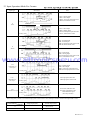
www.alltronicsperu.com
CI Series Multi-function Counter / Timer User Manual
Features:
1. Counting speed is up to 10KCPS;
2. Prescale coefficient 0.001--99.999 can be freely setting;
3. Universal input, NPN or PNP input can be selected by software;
4. With timing function, up to 9 timing mode;
5. Up to two counting / length counting alarm output, one batch
counting alarm output;
6. Applicable to light industries, machinery, packing, food industries,
etc. for quantity and length counting and control output, etc.
For your safty, please read following content carefully before you are using our Meter!
www.alltronicsperu.com
S
KKCIE01-A/1-1
1. Model Illustration
CI□□-R
□□ C 0
0: Without Communication
8: With Communication
Display Digit: 6: 6 digit
Alarm Output: B: One Aalrm C: Two Alarm
Control Ouput: R: Relay Output S: SSR Output
Power Supply: Blank: Switching Power
F: 24VDC
Dimension(mm): 4: 48H x 48W x 94.5L 7: 72H x 72W x 94.5L
8: 48H x 96W x94.5L 16: 80H x160W x83L
CI Series Multi-function Counter / Timer User Manual
24VDC Power Supply can be ordered
2. Model Type
No.
Model
Size (mm)
Output
1
CI16-RC60
80H×160W
Relay Output
2
CI16-RC68
80H×160W
Relay Output
CI8-RC60
48H×96W
Relay Output
6
6
CI8-RC68
48H×96W
Relay Output
6
One Relay
CI7-RC60
Relay Output
6
One Relay
CI7-RC68
Relay Output
6
One Relay
CI4-RC60
Relay Output
6
NO
Display Digit
6
Relay Output
CI4-RC68
Alarm Output
2
Batching Output
One Relay
One Relay
2
One Relay
NO
6
Communication
NO
RS485
NO
RS485
NO
RS485
NO
RS485
3. Technical Specification
Series
CI
Display
Dual Line 6 digit
Power Supply
100-240V AC/DC
www.alltronicsperu.com
Fluctuation range of Allowed Voltage
Input Frequency of INA, INB
Width of Input Pulse
90~110% of Rated Voltage (AC Power)
1Hz、30Hz、1KHz、5KHz、10KHz can be choosed
INA,INHIBIT,RESET,BATCH RESET,can choose 1ms or 20ms
Voltage Input: input impedance 5.4KΩ,“H”:5~30VDC “L”:0~2VDC
No-voltage Input: for Short-circuit impedance is 1KΩ, Residual Voltage: Max 2v dc,
Open-circuit impedance Max 100KΩ
Input
Counter
One-shot Output
Timer
Contact Capacity
Control Output
SSR Capacity
10/50/100/200/500/1000/2000/5000ms
10/50/100/200/500/1000/2000/5000ms
NO:250VAC 3A Impedance
Ten Years
12VDC±10%
Less than 100mA
Ambient Temperature
-10℃~50℃
Unfreezing State
Storage Temperature
-25℃~65℃ Unfreezing State
Ambient Humidity
35-85%RH
Data Saving Time
Power of External Sensor
Time Accuracy
Dielectric Strength
Mechnical
Vibrate
Fault
Mechnical
Impact
Using Life
Active time function Voltage false
Setting False
Temperature False
Min: 100MΩ
2000V AC
Dielectric
Interferance (AC Power)
Fault
NC:250VAC 2A Impedance
Max: 30VDC , Max: 100mA
±2kV
Power On :±0.05%±0.05sec
With Signal :±0.05%±0.03sec
(at500VDC)
50/60Hz one minute
Square-wave generator interference (width of pulse: 1us)
Amplitude:0.75mm
Frequency: 10-55Hz X,Y,Z each direction for one hour
Amplitude:0.5mm
Frequency: 10-55Hz X,Y,Z each direction for ten minutes
(about 30G) X,Y,Z each direction for three times
(about 10G) X,Y,Z each direction for three times
Mechnical
more than 10,000,000 times
Electrical
more than 100,000 times (NO: 250V AC 3A Load
NC: 250V AC 2A Load)
KKCIE01-A/1-2
4. Panel Indication
PS1: Lower line displays OUT1 setting value
PS2: Lower line displays OUT2 setting value
BA.S: Upper line displays batch counting value
Lower line displays batch setting value
Lock: Button lock indication (CI16, CI8 do not with this lamp)
OUT1, OUT2: OUT1 or OUT2 output indication
BA.O: Batch output indication (CI3, CI4 do not with this lamp)
CNT: In the counting status
TMR: In the timing status
PS1
PS2
BA.S
Reset Key
LOCK
OUT1
RST
BA
OUT2
BA.0
CNT
TMR
MD
Batch setting Key
Parameter change Key
Function Key
5. Operation Instruction
1. How to change counter setting value (Example: change the setting calue from 175 to 180)
(1)
(2)
PS1
PS2
BA.S
LOCK
OUT1
RST
BA
OUT2
BA.0
CNT
TMR
In measuring status press
key to
display setting value status, press
key the digit 5 flickers.
PS2
MD
In measuring status press
Press
key or
key 5 times,
change the digit 5 to 0.
PS1
BA.S
LOCK
OUT1
OUT2
RST
BA
MD
BA.0
CNT
TMR
key to display setting value change status, the flickering digit is from right to left circularly.
(4)
(3)
www.alltronicsperu.com
Press
key to choose digit 7
and let it flicker.
PS2
PS1
PS2
BA.S
BA.S
LOCK
OUT1
OUT2
RST
BA
MD
BA.0
CNT
PS1
PS2
BA.S
TMR
LOCK
OUT1
RST
BA
OUT2
BA.0
CNT
TMR
Press
key once to change digit 7
to 8, press
key to confirm the
change and return to measuring status.
MD
2.How to change timer setting value (Output mode is FLK)
t.OFF
Run mode
MD
t.ON
MD
To change timing time
In setting status, the menu will return to timing status automatically if no operation within 60 seconds.
How to change t.OFF time to 50sec from 30sec change t.ON time to 20sec from 40sec (output mode: FLK timing range: 0.1s to 99999.9s).
1
2
Press
key twice to change digit 3
to 5, press
key to confirm the
change and display t.ON setting status.
In timing status press
key to
display t.OFF setting status, press
key the digit 3 flickers.
In timing status press
key to display setting value change status, the flickering digit is from right to left circularly.
3
4
Press
key to choose digit 4
and let it flicker.
Press
key twice to change digit 4
to 2, press
key to confirm the
change and return to timing status.
KKCIE01-A/1-3
Batch counting
Batch counting value counts up, it will not be reset unless external BATCH reset signal is applied.
When batch counting value counts over 999999, it will be reset to 0 and counts again.
Batch couting value is not reset by front
key or external reset signal.
(1) Batch counting in Counting mode.
Batch alarm outputs when counting alarm output quantity is equal to the batch setting value.
When batch control output is used, the time interval of counting up process is bigger than 10mS.
(2) Batch counting in Timing mode.
Batch alarm outputs when timing alarm output quantity is equal to the batch setting value.
In FLK output mode, the counting value of Batch counter is counting up, when Toff and Ton setting time passes.
Batch output action
If batch output is ON, it will keep ON status until batch reset signal is applied.
If batch output is ON, after power off and then power on again, batch output keeps ON status until external reset signal is applied.
2. How to change batch setting value
BA key
Measuring status
MD key
Batch setting value change status
In measuring status press
key to display batch setting value change status. The method for changing batch setting value is the
same as the one for changing counting setting value. Press key to select the digit to be changed to let it flicker, and then press
key to change the value. Press
key to confirm and menu returns to measuring status.
www.alltronicsperu.com
After changing the value, the upper LED will display the current batch counting value.
When batch setting value is bigger than batch counting value, if the setting value is changed (equal or smaller
than the counting value, the batch output takes action.
If batch setting value is 0, the batch output is in OFF state.
When menu is batch setting value change status, if no button operation within 60 second, the menu will return to measuring status.
KKCIE01-A/1-4
8. Lock Key Setting
9.Setting of Counter Function Modes
Select setting (
Setting Mode
、▲)
▲
Input Type
If the output Mode is S, T and D, then input mode just can choose Ud-A, B, C
MD
Max Counting Speed
MD
Counting Speed means the highest frequency of INA and INB allowed input, if
the setting value is 5K, the error will be existed if the input signal over than 5K.
※Up Or Down Input Mode
Output Mode
※Up/Down - A、B、C Input Mode
MD
MD
MD
OUT2 Output
Time
OUT1 Output
Time
Units: ms
Units: ms
Input Logic
www.alltronicsperu.com
MD
: Choose NPN or PNP input type
1 →20
→
Min Reset Time
▲
or
MD
Min Signal width of RESET (mm)
- - - - - -
Decimal Point
→ - - - - - *
→- - - - - *
→ - - - - - *
Memory Retention
MD
→
MD
Key: Shift the flickering digit
Key: Change the Prescale value
Setting range of prescale value is 0.001--99.999
Prescale value: It is actual value of length and position
▲
Prescale Value
▲
MD
Baud Rate
(
Power OFF Counting Value Reset
Power OFF Counting Value Save
Communication Baud is 4800 and 9600 can be choosed
)
MD
MD
Address
(
)
Communication Address: Can be setting freely between
MD
Lock Key
MD
→
→
Counter/ Timer
: Couner
Timer
1. If you choose F or N output mode,, when the counting value reached setting value,the output
will be keeped, there is no “OUT2 output time” menu in function setting mode.
2. If the output Mode is S, T and D, then input mode just can choose Ud-A, B, C. If the input mode want to choose UP/DOWN,
then output mode just can chosoe other modes except S,T,D.
3. If the output mode choose D, when counting frequency over than 1Kcps, please choose SSR output.
4. When the Max counting speed is 5Kcps or 10Kcps, if change output mode to D, counting speed will automatically choose 1Kcps.
5. In the mode of function setting,the external input signal can be accepted, after exit, display value and output will be reset automatically.
KKCIE01-A/1-5
10. Time Function Setting
Setting Menu
Setting
Time Range
MD
U
Up
→
→
Up/Down Mode
Up: from 0 increase to the setting value
Down Down: from setting value decrease to 0
MD
.
Output Mode
MD
Output Time
Unit: ms
Output delay time choose
MD
Input Logic
and
: Input mode choose
Voltage Input
No voltage input
MD
(Unit:ms)
Signal Time Input
INA、INHIBIT、RESET、BATCH RESET choose the Min width of signal
MD
Baud Rate
(
MD
Communication Baud is 4800 and 9600 can be choosed
)
Address
www.alltronicsperu.com
(
MD
)
Communication Address: Can be setting freely between
MD
Lock key
MD
:Counter
:Timer
→
→
Counter/Timer
11.Timing Range
Function Setting
11.Timing Range
Display
0.01s~9999.99s
SEC
0.1s~99999.9s
SEC
1s~999999s
SEC
0.01s~99m59.99s
S
0.1s~999m59.9s
S
Range Display
0.1m~99999.9m
1m~999999m
1s~99h59m59s
1m~9999h59m
H S
H
KKCIE01-A/1-6
12. Input Operation Mode For Counter
Input Type
Note
Illustration
INA: Counting Input
INB: Control Input
INB=L; INA pulse input add count
INB=H; INA forbid to count
No Counting
Counting Value
U
(Add)
No Counting
INA: Control Input
INB: Counting Input
INA=H; INB pulse input add count
INA=L; INB forbid to count
Counting Value
INA: Counting Input
INB: Control Input
INB=L; INA pulse input minus count
INB=H; INA forbid to count
Counting Value
No Counting
Counting Value
D
(Minus)
No Counting
Counting Value
INA: Control Input
INB: Counting Input
INA=H; INB pulse input minus count
INA=L; INB forbid to count
Counting Value
INA: Counting Input
INB: Control Input
INB=L; INA pulse input add count
INB=H; INA input pulse minus count
www.alltronicsperu.com
Ud-a
(Add/ Minus-A)
Order Input
INA input pulse, add count
INB input pulse, minus count
Ud-b
(Add/Minus-B)
Sole Input
Counting Value
INA before, INB add count
INA delay, INB minus count
Phase difference input
(for rotary encoder)
Ud-c
Phase Difference Input
Counting Value
Counting Value
When using rotary encoder’s A, B ohase output, please connect meter’s INA, INB input terminal, and turn the input mode to Ud-C.
Input Type
Symbol
Voltage Input (PNP)
Terminal Input (NPN)
H
5-30VDC
Short Circuit
L
0-2VDC
Open Circuit
KKCIE01-A/1-7
13. Output Operation Mode For Counter
One-shot Output (OUT1 output)
Hold Output
One-shot Output
(OUT2 Output)
Hold Output
Input Mode
Up
Down
Simultaneous Output
Operation after reached the setting
Up/DownA,B,C
Reset
999999
F
SV2
Display
SV1
0
Display will continue to
increase or decrease, output
will be kept to the reset input
OUT1
Output
OUT2
Output
Reset
999999
N
SV2
Display
SV1
0
Display and output will be
kept to the reset input
OUT1
Output
OUT2
Output
Reset
999999
C
SV2
Display
SV1
0
OUT1
Output
OUT2
Output
Reset
999999
R
SV2
Display
SV1
Display value will return to the
start status automatically, output
delay will return to the initial status
after reached the setting time.
(Output activity is repeat single
output)
Display value and output will
automatically return to the initial
status after keep to the delay setting
time.
(Output activity is repeat single
output)
www.alltronicsperu.com
0
OUT1
Output
OUT2
Output
Reset
999999
K
SV2
Display
SV1
0
OUT1
Output
OUT2
Output
Reset
999999
P
Display
SV2
SV1
0
OUT1
Output
OUT2
Display value will continus to
increase or decrease until reset
input, output delay will return to
the initial status after reached
the setting time.
(Output activity is repeat single
output)
Display value kept to the delay
time, will display the next cycle.
(In the delay time, the next cycle
counting and timing from initical
status)
(Output activity is repeat single
output)
Output
Reset
999999
SV2
Display
Q
SV1
0
OUT1
Output
OUT2
Output
Reset
999999
SV2
A
Display
SV1
0
OUT1
Output
OUT2
Output
Display value will continus to
increase or decrease within
output delay time, display value
and output will return to the
initial status after output delay
reached the setting time.
(Output activity is repeat single
output)
Display value and OUT1 output
will be kept to the reset input,
OUT2 output will return to the
initial statusafter reaching the
setting time.
(Output activity is repeat single
output)
KKCIE01-A/1-8
Up/DownA,B,C
Operation
OUT1 and OUT2 meet following
conditions,will keep ON status:
Display Value≥Setting Value 1
Display Value≥Setting Value 2
SV2
SV1
S
OUT1 keeps OFF status when display
value is smaller than the preset 1 value,
but if preset vlaue is “0”, OUT1 keeps
ON status.
When display value is smaller than the
preset value “2”, OUT2 keeps ON
stataus
SV2
SV1
T
SV2
SV1
D
When display value = setting value
OUT1 and OUT2 keeps ON status
When the speed of counter meter setting
to 1kcps, should use SSR output
14. Operation Mode Change
Measuring mode (counting or timing status)
MD Press for 3 seconds
MD Press for 3 seconds
Input Mode (IN)
Time Range
MD
MD
www.alltronicsperu.com
MAX counting speed (CPS)
Up/Down Mode (U-D)
MD
MD
Output Mode (OUT)
Output Mode (OUT)
MD
MD
Output Time (OUT-T)
Output Time (OUT2)
MD
MD
Output Time (OUT1)
Input Logic (SIG)
MD
MD
Input Logic (SIG)
Input Signal Time (In-T)
MD
Counting
Mode
Min Reset Time (RST)
Timing
Mode
MD
Decimal Point (dP)
MD
MD
Prescale Value (SCL)
MD
Counting Value Save (DATA)
MD
Baud Rate (BAUD)
MD
Address (ADD)
MD
Lock key (LOCK)
MD
Counter / Timer (C-T)
※ Under the mode of Counting can directly change to Timing mode;
※.In the mode of function setting, counter will return to the measuring status automatically after
without any operation for 60 seconds.
KKCIE01-A/1-9
Timer Output Operation Mode
One-shot Output
Hold Output
t=One-short output time
t
Time and Sepuence
Output Mode
Activation
1. Timer starts when INA signal turns ON;
when INA signal turns OFF, time reset.
2. Timer starts when power turns ON and
when reset turns OFF during INA signal ON.
3. Control output operate decide by hold or
One-short time.
Power
SIGNAL ON DELAY (POWER OFF RESET)
Power
INA
(OND)
INHIBIT
RESET
t
OUT-2 (Output)
up
UP (Setting Time)
Display
0
Down Down (Setting Time)
0
INA
OUT2
(Output)
Power
INA
INHIBIT
RESET
OUT-2 (Output)
UP (Setting Time)
up
0
Display
Down Down (Setting Time)
0
t
t
t
OUT2
(Output)
Power
INA
(OND.2)
Power
INA
POWER ON DELAY (POWER OFF COUNTING KEEP)
INHIBIT
RESET
T:preset time
1. Timer starts when INA signal turns ON;
when INA signal turns OFF, timing keeps on.
2. counting starts when power turns ON , Reset
signal OFF and INAsignal ON
3. Control output operate decide by hold or One-short time.
SIGNAL ON DELAY 1 (POWER OFF RESET)
(OND.1)
Hold Output
t
t
T:preset time
1. Timing starts when power on and the data will be
keeped when power off.
2. counting starts when reset signal OFF ,Pause
signal OFF and power ON
3. Control output operate decide by hold or One-short time.
HOLD
t
Power
OUT-2 (Output)
UP (Setting Time)
up
0
Display
Down Down (Setting Time)
0
www.alltronicsperu.com
OUT2 T:preset time
(Output)
FLCKER (Power OFF Reset)
Power
INA
(FLK)
INHIBIT
RESET
Power
INA
OUT-2 (Output)
UP (Setting Time)
up
0
Display
Down Down (Setting Time)
OUT2
(Output)
0
FLCKER1 (Power OFF Reset): Hold output
Power
INA
INHIBIT
RESET
OUT2
(Output)
0
FLCKER1 (Power OFF Reset): One-shot output
Power
INA
INHIBIT
RESET
OUT-2 (Output)
up
UP (Setting Time)
0
Display
Down Down (Setting Time)
0
1. Timing starts when INA signal turns on, if INA signal
is accepted, only initial signal is recognized.
2. When power ON , reset signal is OFF and INA signal
ON, it starts to timing.
3. Control output operate decide by hold output, when using
terminal output, the setting time must over than 100ms.
Power
INA
OUT-2 (Output)
UP (Setting Time)
up
0
Display
Down Down (Setting Time)
(FLK.1)
1. Timing starts when INA signal turns on, if INA signal
is applied repeatedly, only initial signal is recognized.
2. When power ON , reset signal is OFF and INA signal
ON, it starts to timing.
3. Control output operation is decided by hold output, when
the time comes to Toff setting time or Ton setting time, output
is ON or OFF. (No One-shot output)
4. Each Ton time and Toff time should be setted sepertately.
5. When using terminal output, the setting time must over
than 100ms.
t
t
t
T: Setting Time
1. Timing starts when INA signal turns on, if INA signal
is accepted, only initial signal is recognized.
2. When power ON , reset signal is OFF and INA signal
ON, it starts to timing.
3. Control output operate decide by one-shot output, when
using terminal output, the setting time must over than 100ms.
Power
INA
OUT2
(Output)
T
T
T
KKCIE01-A/1-10
1. Timing starts when INA signal turns on, if INA signal
is accepted, only initial signal is recognized.
2. Control output operate is decided by Hold output which
will be keeped to the next setting value.
3. When power ON , reset signal is OFF and INA signal
ON, it starts to timing.
3. when using terminal output, the setting time must over
than 100ms.
Power
INA
FLCKER2 (POWER OFF HOLD): HOLD OUTPUT
Power
INA
INHIBIT
RESET
OUT-2 (Output)
UP (Setting Time)
up
0
Display
DownDown (Setting Time)
0
Power
INA
INHIBIT
RESET
OUT-2 (Output)
UP (Setting Time)
up
0
Display
DownDown (Setting Time)
0
t
t
t
t
t
INTERVAL (POWER/SIGNAL RESET)
(INT)
C
HOLD
T
T: Time setting
1. Timing starts when INA signal turns on, if INA signal
is accepted, only initial signal is recognized.
2. Control output operate is decided by One-shot output
which will be keeped to the setting value.
3. When power ON , reset signal is OFF and INA signal
ON, it starts to timing.
3. when using terminal output, the setting time must over
than 100ms.Power
INA
T- C
T
T
C
OUT2
(Output)
HOLD T: Time setting
FLCKER2 (POWER OFF HOLD): One-shot OUTPUT
(FLK)
T- C
T
OUT2
(Output)
1. Timing starts when INA signal turns to ON.
2. Timing reset when INA signal turns to OFF.
3. When power ON, reset signal OFF and INA
signal ON, it starts to timing.
4. Display value and Control output will reset
automatically after reach the setting time.
5. In the process of timing, control output is ON
Power
INA
INHIBIT
RESET
OUT-2 (Output)
UP (Setting Time)
up
0
Display
DownDown (Setting Time)
0
Power
INA
OUT2
(Output)
T
T
T: Time setting
1. When INA signal turns to ON, control output will
turns to ON and starts to counting.
2. If INA signal is repeatedly showed, only initial signal is
recognized.
3. When power ON, reset signal OFF and INA
signal ON, it starts to timing.
4. Display value and Control output will reset
automatically after reach the setting time.
5. In the process of timing, the INA signal keeps ON
Power
INA
INTERVAL (POWER OFF RESET)
Power
INA
INHIBIT
RESET
(INT.1)
OUT-2 (Output)
UP (Setting Time)
up
0
Display
DownDown (Setting Time)
0
www.alltronicsperu.com
INTERVAL 1 (POWER OFF RESET)
(OFD)
T
OUT2
(Output)
T: Time setting
1. When power ON and reset signal OFF, in the time of
INA signal ON, control output will keep ON status.
2.Display value and Control output will reset
automatically after timing reach the setting time.
Power
INA
INHIBIT
RESET
OUT-2 (Output)
UP (Setting Time)
up
0
Display
DownDown (Setting Time)
0
Power
INA
T
OUT2
(Output)
T: Time setting
15.Connection Drawing
CI4
CI7
20 19 18 17 16 15 14 13 12 11
1
CI8
AL1
AL2
10
9
8
7
6
BATCH
5
4
3
POWER
AC/DC
100-240V
2
I NB
BBATCH
A T C H INHIBIT
I N H IBI T R E S E T G N D +12V INB
R ESE T
RESET
1
IINA
NA
2
3
4
5
6
8
7
9
10
POWER
CI16
~
AL2
11
12
AL1
13
14
BATCH
R E SE
RE
SET
ATCH
BBATCH
15
IINN HI
H I B IT
IT
1 0 0~ 2 4 0 V A C
16
17
18
19
20
RESET
GND
+12V
IINB
NB
IINN A
Note: If there is any change, please subject to the drawing on the meter!
KKCIE01-A/1-11
16. Input Connection
1. Input logic: without voltage input (NPN)
(1). SSR input
Standard sensor: NPN output
Sensor
(2) Terminal Connection
Timer/Counter
Timer/Counter
+12V
5.4kΩ
+12V
5.4kΩ
Inner Circuit
Inner Circuit
GND
GND
counting speed: 1 or 30cps setting (counter)
2. Input logic : voltage input (PNP)
(1). SSR input
Standard sensor: NPN output
Sensor
(2) Terminal Connection
Timer/Counter
Timer/Counter
+12V
+12V
Inner Circuit
Inner Circuit
5.4kΩ
5.4kΩ
GND
GND
counting speed: 1 or 30cps setting (counter)
17. Output Connection
Relay Output
Timer/Counter
SSR Output
Timer/Counter
Load
(+)
SSR Output:
1. Please use adaptable load and power, SSR output
can not over then ON/OFF, capacity (30VDC, less than100mA)
2. Making sure that the power connected in the right way,
3. When using Inductive load(Relay, etc), Filter circuit(Diode, etc)
must connect to the load ends
www.alltronicsperu.com
Load Power
(-)
Load
Power
(DC)
Load
18. Dimension
Side Face Size
Panel Size
A
Mounting Size
G +0.5
-0
C
E
D
H
J +0.5
-0
B
F
K
Model
A
B
C
D
E
F
G
H(Min)
J
K(Min)
CI4:(48*48)
48
48
97.5
3
94.5
45
45.5
25
45.5
25
CI7:(72*72)
72
72
97.5
3
94.5
67
67.5
25
67.5
25
CI8:(48*96)
96
48
97.5
3
94.5
44.5
90
25
45
25
30
155.5
30
CI16:(160*80)
160
80
96
13
83
155
76
www.alltronicsperu.com
.


![H8DA(M)JA [轉換].ai - Anly Electronics Co., Ltd.](http://vs1.manualzilla.com/store/data/005792054_1-e40506c7505a129d0c559401a2fa00b1-150x150.png)

![H5DA(M)IA [轉換].ai - Anly Electronics Co., Ltd.](http://vs1.manualzilla.com/store/data/005881219_1-4b829119a0226e59b0b94ecac6325c4d-150x150.png)