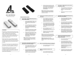
1
ZME*KFOBC
Version 1.3
This remote control has two modes: the normal
operation for daily use and management mode for setup.
Pushing all four buttons for 5 sec. turns the device into
management mode (indicated by slow blinking green LED).
Management mode time-out is 10 sec. In factory default
mode pushing one of the four buttons for 1 sec will start
different inclusion modes:
* Button 1: Include KFOB as secondary controller
* Button 2: Include KFOB as sec. controller - non secure
* Button 3: Include new device into KFOBs network
* Button 4: Include new device into network - non secure
Control options also include special modes like 'all on/off'
or always controlling the Z-Wave device in proximity to the
fob. The device supports secure communication when
included with enhanced security option and when
communicating to a device also supporting enhanced
security option. Otherwise the device will automatically turn
into normal communication. to maintain backward
compatibility.
Installation Guidelines
The device comes ready to use with a battery already
installed. A single click on any button will include the
device in this status. For battery change the device needs
to be opened by removing the three little screws on the
back-side of the device. Use a screwdriver or any other
usable device to gently push out the battery as shown on
the picture. During reassembly watch the position of the
white rubber and the make sure the silver buttons fit
exactly into the nipples of the rubber. The device can be
operated in two different modes: the operation mode and
the management mode:
•
•
The process for button 1 and 2 are indicated with fast
red/green blinking, the process for button 3 and 4 show a
fast green blinking. Every button push stops the process.
This fast inclusion only works when device is in factory
default. Once one device is included or the fob is included
as secondary controller further inclusion and exclusion
operation require to turn the device into management
mode. In management mode
* Button 1: Include/Exclude being a sec controller
* Button 2: Sends Wakeup Notification and send out NIF
* Button 3 + short on 1: Start Secure Inclusion
* Button 3 + short on button 2: Start Unsecure Inclusion
* Button 3 + short on button 3: Start Exclusion
* Button 3 + short on button 4: Start Primary Handover
In management mode the following actions can be
performed:
•
•
•
Please refer to the chapters below for detailed information
about all aspects of the products usage.
Product description
The Secure Key Fob Controller is a 4-button Z-Wave
device capable to act both as primary or secondary
controller. The four buttons can control other Z-Wave
devices such as switches, dimmer and even door
locks directly. Various options - configurable by Z-Wave
configuration commands - define the actions and the
commands used for this control. It is possible to use two
sets of buttons (one of on/open/up and one for
off/closed/down) or 4 single buttons to control 4 different
groups of devices.
The controller also allows triggering scenes in a central
controller. Again different modes can be configured to
adapt to the various implementations of scenes in different
central controllers in the market.
Operation Mode: This is the mode where the device
is controlling other devices.
Management Mode: The device is turned into the
management mode by pushing all four buttons for 5
sec. A blinking LED indicates the management mode.
In the management mode buttons of the device have
different functions. If no further action is performed the
device will turn back to the normal mode after 10 sec.
Any management action terminates the management
mode as well.
•
Button 1 - Inclusion/Exclusion: Every inclusion or
exclusion attempt is confirmed by hitting this button.
This mode times out after 20 seconds or can be
stopped by any button.
Button 2 - Send Node Information Frame and Wake up
Notification. (see explanation below)
Button
3Activates
the
primary
controller
management menu. The following sub menu items are
available:
o
Button 3 + button 1: Start Secure Inclusion
o
Button 3 + button 2: Start Unsecure Inclusion
o
Button 3 + button 3: Start Exclusion
o
Button 3 + button 4: Start Primary Handover
Button 4 - Enter into Association mode to assign target
devices to the 4 association groups.
Factory Reset
The device can be set back to factory defaults without
performing an exclusion process. Please execute the
following steps: (1) Turn the device into Management
Mode, (2) click on Button 3, (3) keep button 4 pushed for
4 seconds.
Behavior within the Z-Wave network
On factory default the device does not belong to any ZWave network. The device needs to join an existing
wireless network to communicate with the devices of this
network. This process is called Inclusion. Devices can
also leave a network. This process is called Exclusion.
Both processes are initiated by the primary controller of the
Z-Wave network. This controller will be turned into
exclusion respective inclusion mode. Please refer to your
primary controllers manual on how to turn your controller
into inclusion or exclusion mode. Only if the primary
controller is in inclusion or exclusion mode, this device can
join or leave the network. Leaving the network - i.e. being
excluded - sets the device back to factory default.
If the device already belongs to a network, follow the
exclusion process before including it in your network.
Otherwise inclusion of this device will fail. If the controller
being included was a primary controller, it has to be reset
first.
Please check the instructions in the quick start section how
to include and exclude the device from a network.
Operating the device
Depending on the button mode and operating modes
configured using the configuration parameters the key fob
can be used in different ways.
previous mode and allows to control two further control
groups C and D using double clicks.
Operating modes for direct device control:
The devices supports 8 different operating modes - this
means the kind of command sent out when pushing a
button. Operating modes either directly control other
devices or they issue various scene activation commands
to a central controller. Operating modes for direct device
control are:
•
Button modes:
•
4 Groups are controlled with single button (parameter
1 and 2 = 0) The four buttons 1-4 control one single control
group each: 1->A, 2->B, 3->C, 4->D. Single click turns
devices in the control group on, double click turns them off.
Click and hold can be used for dimming.
•
•
•
2 Groups are controlled with two buttons (parameter 1
and 2 = 1) The buttons 1 and 3 control the control group A
(button on turns on, buttons turns off), the buttons 2 and 4
control the control group B (button on turns on, buttons
turns off). In case dimmers are controlled, holding down
the larger button will dim up, holding down the smaller
button will dim down the load. Releasing the button will
stop the dimming function.
Operating modes for scene activation:
•
•
4 Groups are controlled with two buttons and double
click (parameter 1 and 2 = 2) This mode enhances the
Direct Control of associated devices with
On/Off/Dim commands (parameter 11…14 = 1).
Devices are controlled using Basic Set On/Off
commands and Switch-Multilevel Dim Start/Stop.
Direct Control of associated devices with only
On/Off commands (parameter 11…14 = 2). Devices
are controlled using only Basic Set On/Off commands.
On Dim-Up event On is sent, on Dim-Down Off is sent.
Direct Control of Devices in proximity (parameter
11…14 = 6). Basic Set and Switch-Multilevel Dim
commands are sent to a device in proximity (50...100
cm) from the Fob. Attention: In case there are more
than one Z-Wave devices nearby all these devices may
be switched. For this reason the proximity function
should be handled with care.
Switch All commands (parameter 11…14 = 3) In this
mode a all neighboring devices will receive Switch-All
Set On/Off command and interpret it according to their
membership in Switch-All groups. This mode
implements communication pattern 7.
Door Lock Control (parameter 11…14 = 7) This mode
allows direct control (open/close) of electronic door
locks using secure communication.
Direct
Activation
of
preconfigured
scenes
(parameter 11…14 = 5) Associated devices in an
association group are controlled by individual
commands defined by Z-Wave command class ‘Scene
Controller Configuration’. This mode enhances
mode Direct Control of associated devices with
On/Off/Dim commands . Please turn the button mode
to 'separate' to allows different scene id on every
button.
Scene Activation in IP Gateway (parameter 111…14
= 4) If configured correctly the buttons can trigger a
scene in a gateway. The scene number triggered is a
combination of the group number and the action
performed on the button and has always two digits. The
group number defines the upper digit of the scene
number, the action the lower digit. The following actions
are possible:
• 1 = On
•
•
•
•
•
of the device is confirmed by sending out a Node
Information Frame. Beside this it may be needed for
certain network operations to send out a Node Information
Frame. Pressing Button 2 in management mode will issue
a Node Information Frame.
2 = Off
3 = Dim Up Start
4 = Dim Down Start
5 = Dim Up Stop
6 = Dim Down Stop
Example: Clicking/double clicking the button will issue
scene triggers, scene 11 (button 1 click, event on), scene
12 (button double click 1, event off, single button control is
used in this example)
•
Activation of Central Scenes (parameter 11…14 = 8,
Default) Z-Wave Plus introduces a new process for
scene activation - the central scene control. Pushing a
button and releasing a button sends a certain command
to the central controller using the lifeline association
group. This allows reacting both on button push and
button release. This mode implements communication
patterns 6 but requires a central gateway supporting ZWave Plus.
Wakeup
Intervals
how
communicate with the device?
to
This device is battery operated and turned into deep sleep
state most of the time to save battery life-time.
Communication with the device is limited. In order to
communicate with the device, a static controller C is
needed in the network. This controller will maintain a
mailbox for the battery operated devices and store
commands that can’t be received during deep sleep state.
Without such a controller, communication may become
impossible and/or the battery life-time is significantly
decreased.
This device will wakeup regularly and announce the
wakeup state by sending out a so-called Wakeup
Notification. The controller can then empty the mailbox.
Therefore, the device needs to be configured with the
desired wakeup interval and the node ID of the controller. If
the device was included by a static controller this controller
will usually perform all necessary configurations. The
wakeup interval is a tradeoff between maximal battery lifetime and the desired responses of the device. The device
will stay awake right after inclusion for 10 seconds allowing
the controller to perform certain configuration. It is possible
to manually wake up the device by pushing button 2 in
management mode.
The minimum allowed wakeup time is 240s but it’s strongly
recommended to define a much longer interval. The device
has a periodic wakeup function however this function is
disabled by the configuration parameter #25. This will
protect the battery in case the controller is accidently
configuring a wakeup interval. A wakeup of the fob outside
the range of the controller will lead to lots of unsuccessful
communication attempts draining the battery. Defining
Node id of 0 as a destination of the Wake up Notification
will disable the periodical wakeup function as well.
Node Information Frame
The Node Information Frame is the business card of a ZWave device. It contains information about the device type
and the technical capabilities. The inclusion and exclusion
LED Control
•
•
•
•
•
•
•
Confirmation - green 1 sec
Failure - red 1 sec
Button press confirmation - green 1/4 sec
Waiting for Network Man. mode - slow green blinks
Waiting for association selection - green fast blink
Waiting for primary controller function - green fast blink
Waiting for NIF in Association Set Mode - green-red-off
Associations
Z-Wave devices control other Z-Wave devices. The
relationship between one device controlling another device
is called association. In order to control a different device,
the controlling device needs to maintain a list of devices
that will receive controlling commands. These lists are
called association groups and they are always related to
certain events (e.g. button pressed, sensor triggers, ...). In
case the event happens all devices stored in the respective
association group will receive a common wireless
command.
Association Groups:
1
Lifeline (max. nodes in group: 10)
2
Control Group A, controlled by button 1 or single
clicks of buttons 1 and 3 (max. nodes in group: 10)
3
Control Group B, controlled by button 2 or single
clicks of buttons 2 and 4 (max. nodes in group: 10)
4
Control Group C, controlled by button 3 or double
clicks of buttons 1 and 3 (max. nodes in group: 10)
5
Control Group D, controlled by button 4 or double
clicks of buttons 2 and 4 (max. nodes in group: 10)
Set/unset associations to actuators
Associations can be assigned and remove either via ZWave commands or using the device itself.
To control a Z-Wave device from the Key Fob the node ID
of this device needs to be assigned to one of the four
association groups. This is a three-step process:
1. Turn the Key Fob into management mode and hit
button 4 within 10 sec. (LED is blinking green when
management mode is reached).
2. Within 10 sec. push the button you like the Z-Wave
actuator to be assigned with. After 10 sec. the devices
goes back to sleep. Single click means adding to
this association group, double click means
removing the node selected in step (3) from this
association group.
3. Find the Z-Wave actuator you like to control by the key
fob. Hit the button on the device to issue a Node
Information Frame within 20 sec. A common way is
hitting a control button one or three times. Please
consult the manual of the device to be controlled for
more information how to issue an Node Information
Frame. Any button press on Key Fob at this stage will
terminate the process.
Command
to
Control
Group
A-D (Parameter
Number 11-14, Parameter Size 1) This parameter defines
the command to be sent to devices of control group A
when the related button is pressed
Value
Description
0
Disabled
1
Switch On/Off and Dim (send Basic Set and
Switch Multilevel)
2
Switch On/Off only (send Basic Set)
3
Switch All
4
Send Scenes
Please refer to the Quick start and the Installation section
for information how to use this device as a primary
controller including other Z-Wave devices.
5
Send Preconfigured Scenes
6
Control devices in proximity
Exclude device from network
7
Control Door Lock
8
Central Scene to Gateway (Default)
Special Functions as Z-Wave Controller
As a primary controller the device can include and exclude
other devices in its own network, manage associations,
and reorganize the network in case of problems.
Include other device in own network
Turn into management mode. Now hit button 3 to activate
the primary controller functions. The green LED will blink
faster. Now Hit Button 3 again to turn the controller into
exclusion state. Consult the manual of the new device how
to start the exclusion process.
Attention: Removing a device from the network means that
it is turned back into factory default status. This process
can also exclude devices from it's previous network.
Shift Primary Role to a different Controller
The device can hand over its primary role to another
controller and become secondary controller. Turn into
management mode. Now hit button 3 to activate the
primary controller functions. The green LED will blink
faster. Now Hit Button 4 to turn the controller into primary
shift mode. Consult the manual of the new device how to
start the primary shift process for the new primary
controller.
Configuration Parameters
Z-Wave products are supposed to work out of the box after
inclusion, however certain configuration can adapt the
function better to user needs or unlock further enhanced
features.
Button 1/3 or 2/4 pair mode (Parameter Number 1(1/3)
and
Number
2(2/4), Parameter
Size 1)
In separate mode button 1/2 works with group A, button
3/4 with group C. Click is On, Hold is dimming Up, Double
click is Off, Click-Hold is dimming Down. In pair button
1+3/2+3 are Up/Down correspondingly. Click is On/Off,
Hold dimms Up/Down. Single clicks work with group A,
double click with group C.
Value
Description
0
Separately
1
In pair without double clicks
(Default)
2
In pair with double clicks
Send the following Switch All commands (Parameter
Number 21, Parameter Size 1)
Value
Description
1
Switch off only (Default)
2
Switch on only
255
Switch all on and off
Invert
Size 1)
buttons (Parameter
Value
Description
0
No (Default)
1
Yes
Number 22, Parameter
Blocks wakeup even when wakeup interval is
set (Parameter Number 25, Parameter Size 1) If the
KFOB wakes up and there is no controller nearby, several
unsuccessful communication attempts will drain battery
Value
Description
0
Wakeup is blocked (Default)
1
Wakeup is possible if configured accordingly.
Send
unsolicited
Battery
Report
on
Up (Parameter Number 30, Parameter Size 1)
Value
Description
0
No
1
To same node as
notification (Default)
2
Broadcast to neighbors
wake
Wake
up
This is a simplified version of the
device manual. Please refer to
www.zwave.me for the complete
manual.