1
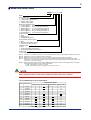
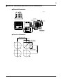
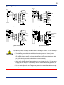
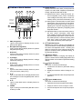
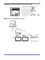
User’s Manual Model PR201 Power Monitor IM 77C01C01-01E IM 77C01C01-01E 3rd Edition Blank Page 1 ■ How to Install NOTE (1) To install the product, select a location where: • no one may accidentally touch the terminals, • mechanical vibrations are minimal, • corrosive gas is minimal, • Ambient temperature: 0 to 50°C; Ambient humidity: 50 to 90%RH And the fluctuation is minimal, • no direct radiant heat is present, • no magnetic disturbances are caused, • no wind blows against the terminal board (reference junction compensation element), • no water is splashed, • no flammable materials are around, (2) Make sure to connect the grounding. (3) Turn off the product before installation and wiring. (4) Use the power supply within specifications. (5) Observe the following instructions for correct installation: Recommended panel thickness is 1 to 10mm. Install the product horizontally. Install the product using attached fixture from the backside of the product. Turn the screw only up to 180° after the screw touches the mounting panel to prevent the case deformation by tightening the screw excessively. (6) Observe the following instructions for correct wiring: M3 screw terminal connection (output, communication, optional integrated control signal) M4 screw terminal connection (input, power supply) Applicable wire size for input signal and power supply is 1.25mm2 or more of cross sectional area. IM 77C01C01-01E 3rd Edition : 2004.06.01-00 2 ■ Model and Suffix Codes PR201- 䊐 䊐 䊐 䊐 䊐 -20 Model Phase & Wire Type 1: 1-phase 2-wire system 2: 1-phase 3-wire system (Note 1) 3: 3-phase 3-wire system 4: 3-phase 4-wire system Rated Input Voltage / Current 1: 110V/1A (Note 2) A: 64V (110V/√ 3) /1A (Note 4) 2: 110V/5A (Note 2) B: 64V (110V/√ 3) /5A (Note 4) 3: 220V/1A (Note 1) C: 127V (220V/√ 3) /1A (Note 4) 4: 220V/5A (Note 1) D: 127V (220V/√ 3) /5A (Note 4) 5: 440V/1A (Note 3) E: 277V (480V/√ 3) /1A (Note 4) 6: 440V/5A (Note 3) F: 277V (480V/√ 3) /5A (Note 4) Output Function 0: None 1: Analog output 2: Integrated pulse output Communication Output Function 0: None 1: RS-485 Communication Output 2: LON Communication Output Optional Function 0: None 1: Power Factor Measuring Function 2: Current 2 Measuring Function (Note 5) Power Supply 2: 85 to 264V AC (Note 1) (Note 2) (Note 3) (Note 4) Input specs. of 1-phase 3-wire system can only select rated input 3 and 4. Input voltage is 200VAC (100V+100V). Rated input 1, 2 (110V) can also be used at 120V input. Rated input 5, 6 (440V) is the specs. only for 1-phase 2-wire system and 3-phase 3-wire system. Rated input A to F is the specs. for only 3-phase 4-wire system. Rated input voltage indicates phase voltage. A, B: 64V, C, D: 127V, E,F: 227V indicate 110V/√3, 220V/√3, 480V/√3 respectively. In case of 440V/√3 input, it can be used at E, F: 227V of rated input. (Note 5) Specify this option when the previous style UZ005(S2.0) with option “Current 2 measuring Function” is required. Current measuring object of current 2 measuring function: 1-phase 3-wire system : I2current r.m.s. value 3-phase 3-wire and 3-phase 4-wire system : I3 current r.m.s. value NOTE Before using the product, check that its model and suffix codes as you ordered. LIST OF COMBINATION OF PR201 RATED INPUT Phase & Wire System Code Rated Input 1 2 3 4 5 6 A B C D E F 110V/1A 110V/5A 220V/1A 220V/5A 440V/1A 440V/5A 64V/1A 64V/5A 127V/1A 127V/5A 277V/1A 277V/5A 1-phase 2-wire 1-phase 3-wire 3-phase 3-wire 3-phase 4-wire 䊊 䊊 䊊 䊊 䊊 䊊 䊊: Available 䊊* 䊊* 䊊 䊊 䊊 䊊 䊊 䊊 䊊 䊊 䊊 䊊 䊊 䊊 䊊 䊊 䊊 䊊 :Not available *200V AC (100V+100V) IM 77C01C01-01E 3rd Edition : 2004.06.01-00 3 ■ External Dimensions and Panel Cutout Dimensions ● External Dimensions Unit: mm 9-Screw M3 45 10-Screw M4 4-Screw M4 V A COS φ ×10 ×103 6 45 kWh Wh W R S COMM 45 110 T SET/ENT 110 2-Bolt M5 Panel Thickness 15 1 to 10 66 82.4 15 96 0.5 45 Short Bar (When short-ciruit, end terminal ON) ● Panel Cut Dimension Minimum130 2-φ6 Hole Minimum 117 φ101 Hole 45±0.3 45±0.3 45±0.3 45±0.3 IM 77C01C01-01E 3rd Edition : 2004.06.01-00 4 ■ Mounting the Product Turn off the power to the product before installing it on the panel because there is a possibility of electric shock. CAUTION After opening the mounting hole on the panel, follow the procedures below to install the product: 1. Insert the product into the opening from the front of the panel so that the terminal board on the rear is at the far side. 2. Set the brackets in place on the top and bottom of the product as shown in the figure below, then tighten the screws of the brackets. Take care not to overtighten them. Directionm to insert the product Insert the product into the opening at the front of the panel ■ Terminal Arrangement 11 1 2 3 4 12 13 21 15 6 7 8 9 10 20 14 5 16 17 22 23 18 19 F05.EPS TML 1-phase No. 2-wire 1 1S 2 1L 3 4 5 6 7 P1 8 P2 9 10 11 12 13 14 15 16 17 18 19 20 21 22 23 Signal 3-phase 3-phase 3-wire 4-wire 1S 1S 1L 1L 3S 2S 3L 2L 3S 3L P1 P1 P0 P2 P2 P3 P3 1-phase 3-wire 1S 1L 2S 2L P1 P0 P2 + – A B C Input Output Communication Communication Terminating + – L N Optional Integrated Control Signal Power Supply GND T14.EPS IM 77C01C01-01E 3rd Edition : 2004.06.01-00 5 ■ Wiring Diagrams Power Side 1 2 (R) (S) Power Side 1 PT + Receiver - Device 11 K CT 1S 1L L 2 P1 P2 8 - 12 3 13 20 14 21 5 7 9 10 15 23 17 19 Power Supply 11 K CT L 1S 1L 2S 2L K CT L 22 16 18 L N PT + Receiver - Device A B Communication C Shield 1 4 6 + 2 N (R) (S) (T) P1 GND Load Side 6 15 7 22 16 9 23 GND 17 18 Power Supply + Short Terminating - Voltage or Contact Power Side 2 N 1 PT K CT 1S 1L 3S 3L L P1 P2 P3 2 1 3 4 6 8 5 7 9 10 Load Side (R) (S) + Receiver - Device 11 K CT L 21 N 5 L 1 phase 3 wire system 3 (R) (S) (T) 20 14 Load Side Power Side 2 13 19 1 phase 2 wire system 1 12 3 10 Short Terminating Voltage or Contact 1 4 P2 8 + - 2 A B Communication C Shield + - 12 20 14 21 15 23 17 18 19 + Receiver - Device 11 K CT L Power Supply N L K CT L 22 16 GND K CT L 2 12 3 13 6 5 7 9 Short Terminating 10 Voltage or Contact Load Side 3 phase 3 wire system 1 4 8 + - PT A B Communication C Shield + 13 3 (T) A Communication B C Shield + - 14 15 18 19 L 21 N Power Supply 22 16 17 20 23 + - GND Short Terminating Voltage or Contact 3 phase 4 wire system The following caution for safety should be taken for handling of product. We are not responsible for damage incurred by use contrary to caution. CAUTION • The following items should be checked before turning power on. Use of product ignoring specifications may cause over heating or burning. (a) Voltage of power supply and input value applied to the product should meet with required specifications. (b) External wiring to terminals should be connected correctly. (See precding Article 4) • When take off wiring from the product, check to see primary side of CT, PT and power supply is in OFF status. If CT secondary side is in OPEN status during operation, be careful for danger of high voltage. • Do not use the product in such dangerous places where exist inflammable and explosive gas or steam. IM 77C01C01-01E 3rd Edition : 2004.06.01-00 6 ■ Outline of Each Section 1 2 3 4 5 Data display (7seg LED) 10 Display Section Display measured value data, preset parameter symbol, set value data, adjustment parameter symbol, adjustment data and the like. 6 (1) Measurement items: integrated power, optional integrated power, power momentary value voltage momentary value, current momentary value, power factor momentary value 10 (2) Setting items: RS-485 station number, data transmission rate, lower limit of input range, upper limit of input range, PT ratio, CT ratio, integrating low cut power, integrating pulse unit (fixed point part, exponent), integrating pulse ON pulse duration 7 Status indicator (LED-RED) 8 9 SET/ENT Panel switch 11 1 12 13 (3) Adjustment items: power momentary value input zero, power momentary value input span,voltage momentary value input zero, voltage momentary input span, current momentary value input zero, current momentary value input span, power momentary value input zero, power momentary value input span 14 kWh (Integration) Light on when data on Display Section is integrated power [kWh]. 2 Wh (Optional Integration) Light on when data on Display Section is optional integrated power [Wh]. 3 W (Power) Light on when data on Display Section is power momentary value [W]. 4 V (Voltage) Light on when data on Display Section is voltage momentary value [V]. 5 A (Current) Light on when data on Display Section is current momentary value [A]. 6 cos φ Light on when data on Display Section is power factor momentary value [cos φ]. 11 SET/ENT SET/ENT Switch This switch is used for changing over displays of screens and items. It is also used for registration of set values and adjusted values. Pressing the switch for 3 seconds or more changes over the displays for measured value, parameter setting, or input/output adjusting. 12 Range Switch This switch is used for changing over display of phases. It is also used for shifting digit position and decimal position of set values on parameter setting display. 13 Figure UP switch This switch is used for the followings: 1. Increase the set value on parameter setting display. 2. Display the maximum value of voltage or current. 7 X 10³ Light on when data value on Display Section is kilo unit. And light on when integrated power value is mega unit. 8 X 10⁶ Light on when data value on Display Section is mega unit. This switch is used for the followings: COMM Light on during communication (RS-485 communication) is made. 2. Display the minimum value of voltage or current 3. Decrease the adjusted value at input/output adjustment 9 3. Increase the adjusted value at input/output adjustment. I 14 Figure DOWN switch 1. Parameter decrement at parameter setting. IM 77C01C01-01E 3rd Edition : 2004.06.01-00 [V] display [A] display [W] display [kWh] display [Wh] display *1 Screen Development Sequence SET/ENT Key used LON communication max/min. Data transmission period setting (second) *4 LON communication max/min. Data transmission period setting (minute) *4 LON communication power data transmission period setting (second) *4 LON communication power data transmission period setting (minute) *4 LON communication integrated power data transmission period setting (second) *4 Integrated pulse unit mantissa setting *4 Integrated pulse unit characteristic setting *4 Integrated pulse ON width setting *4 RS-485 communication protocol setting *4 RS-485 station number setting *4 RS-485 data baud rate setting *4 LON communication node number setting *4 LON communication integrated power data transmission period setting (minute) *4 Input scaling “H” level setting for analog output *4 Turn-off mode ON/OFF setting Turn-off mode time setting Input scaling “L” level setting for analog output *4 PT ratio setting CT ratio setting Integrated low-cut power setting Parameter Setting Screen *2 Screen Development Sequence SET/ENT Key used Analog output zero level adjust Analog output span level adjust Optional instantaneous input span level adjust Optional instantaneous input zero level adjust Instantaneous current input span level adjust Instantaneous current input zero level adjust Instantaneous voltage input span level adjust Instantaneous voltage input zero level adjust Instantaneous power input span level adjust Instantaneous power input zero level adjust Input/Output Adjust Screen *1: Press SET/ENT key till the PT Ratio Setting Screen is displayed. *2: Press SET/ENT key till the Instantaneous Power Input Zero Level Adjust Setting Screen is displayed. *3: Press SET/ENT key till the last MEASURED VALUE DISPLAY SCREEN is displayed. *4: By-passed if option is none. *: If no key operation continues during five minutes when INPUT/OUTPUT ADJUST DISPLAY SCREEN or PARAMETER SETUP DISPLAY SCREEN are displayed, the display screen changes to VALUE DISPLAY SCREEN and displays the last measured value. Instantaneous power [cosf] display factor value Integrated power Optional integrated power Instantaneous power value Voltage r.m.s. value Current r.m.s. value Measured Value Display Screen *3 7 ■ Schematic Diagram of Change-over Display Screen Screen Development Sequence SET/ENT Key used IM 77C01C01-01E 3rd Edition : 2004.06.01-00 8 ■ Example of Parameter Setting Screen (PT Ratio Setting) 1 Display Setting Screen at pressing SET/ENT key within three seconds 2 Change decimal point position at pressing 3 Fixing decimal point position at pressing 7 SET/ENT key 4 Change numeral column at pressing key 5 Change numeral column at pressing and 6 Fixing numeral value at pressing 2, 4 key key SET/ENT key 7 Light on and off of setting value. 8 If the setting is complete correctly, press SET/ENT If required correcting, press any of 1, 3, 6 SET/ENT key. key, key, and key, then repeat from step 1. 5 ■ Example of Communication Connection RS232-C Cable SG B+ A– RS232-C Converter Short-circuit terminating Power monitor # 1 Power monitor # 2 15 16 17 Shield B+ 13 14 A– Shield B+ 13 14 15 A– Shield B+ A– 13 14 15 PR201 Power monitor # N (N31) IM 77C01C01-01E 3rd Edition : 2004.06.01-00 9 ■ Specifications ● Input & Output Specifications Input Specs. Phase & wire system: 1-phase 2-wire system, 1-phase 3-wire system, 3-phase 3-wire system, 3-phase 4-wire system Input frequency: 45 to 65Hz Rated input voltage: 110V AC, 220V AC, 440V AC, 3-phase 4-wire system: 64V AC, 127V AC, 277V AC Permissible Input voltage: 1.2 times of rated voltage (continuous) , 1.5 times (10 seconds) Rated input current: 1A AC, 5A AC Permissible Input current: 1.2 times of rated current (coninuous) , 2 times (10 seconds), 10 times (3 seconds) Input (power) measuring range (secondary side of PT, CT when CT, PT are set) • 1-phase 2-wire system Input (AC) 110V/1A 110V/5A 220V/1A 220V/5A 440V/1A 440V/5A Input range RP 100W -120 to +120W 500W -600 to +600W 200W -240 to +240W 1000W -1200 to +1200W 400W -480 to +480W 2000W -2400 to +2400W App. Consumed VA Voltage Current 0.2VA 0.4VA 0.2VA 200V/1A 200V/5A RP Input range 110V/1A 110V/5A 220V/1A 220V/5A 440V/1A 440V/5A App. Consumed VA Voltage Current 200W -240 to +240W 0.2VA/ 1000W -1200 to +1200W phase 0.2VA/ phase App. Consumed VA Input range Voltage Current RP 200W -240 to +240W 0.2VA/ 1000W -1200 to +1200W phase 0.2VA/ 400W -480 to +480W 0.4VA/ phase 2000W -2400 to +2400W phase 800W -960 to +960W 0.8VA/ 4000W -4800 to +4800W phase • 3-phase 4-wire system Input (AC) 110V/1A 110V/5A 220V/1A 220V/5A 64V/1A 64V/5A 127V/1A 127V/5A 277V/1A 277V/5A RP 300W 1500W 600W 3000W 200W 1000W 400W 2000W 800W 4000W Input range -360 to +360W -1800 to +1800W -720 to +720W -3600 to +3600W -240 to +240W -1200 to +1200W -480 to +480W -2400 to +2400W -960 to +960W -4800 to +4800W Contact signal Voltage signal below 200‰ –1V DC, below 200‰ over 100k‰ 4.5 to 25V DC ON signal: Optional integration start (reset, integration start) OFF signal: Optional integration stop (Note) Control of optional integration can also be made through communication. Control by communication is once made, only control by communication is once made, only control by communication is made thereafter. Integratad lowcut power: Integrated lowcut power below lowcut power is not made by integrated power, optional integrated power and integrated pulse output. Set integrated lowcut power for input to this instrument . Setting range Fixed decimal point Integrated lowcut power 0.1 to 99.9W 0.5W when shipment • 3-phase 3-wire system Input (AC) ON signal OFF signal Parameter setting screen item 0.8VA • 1-phase 3-wire system Input (AC) When outer set of PT, CT, check to see the primary side input power is less than 10000 MW and the value calculated by the formula below is within above input measuring range list. Input range (W) = Primary side input power (W) (PT ratio) x (CT ratio) Rated power factor: LEAD 0.5 to 1 to LAG 0.5 <Optional integrated control signal> Input point: 1 point Input signal: contact or voltage App. Consumed VA Voltage Current 0.2VA/ phase 0.4VA/ phase 0.1VA/ phase 0.2VA/ phase Output Specs. Output point: 1 point (commonly used for analog and integrated pulse outputs) <Analog Output> Function: Conversion of output instantanous power into DC current. Output signal (instantanous power) : 4 to 20mA DC Permissible load resistance: 0 to 750Ω Input scaling: Indicates instantanous power range to be converted. Input scaling can be set by “H” and “L” levls of analog output on parameter setting screen. Set “L” and “H” levels within measuring range of this instrument. Also set span (difference between “L” level and “H” level) so as it would be more than 50% of rated power. If not specified when ordering, it would be shipped “L” level at OW, and “H” level at rated power (W). <Integrated pulse output> Function: Outputs pulse in proportion to integrated power Output signal: Open collector Output capacity: 200mA, 30V DC Integrated pulse unit: Indicates actual kWh corresponding 1 pulse input to this instrument. It can be set through integrated pulse unit characteristic and mantissa sections on parameter setting screen. 0.2VA/ phase 0.5VA/ phase RP=Rated Power IM 77C01C01-01E 3rd Edition : 2004.06.01-00 10 Rated power 100W 200W 300W 400W 500W 600W 800W 1000W 1500W 2000W 3000W 4000W Setting range 5.556 × 10⁻⁶ to 1.000 × 10⁻¹kWh/pulse 6.667 × 10⁻⁶ to 1.000 × 10⁻¹kWh/pulse 1.000 × 10⁻⁵ to 1.000 × 10⁻¹kWh/pulse 1.334 × 10⁻⁵ to 1.000 × 10⁻¹kWh/pulse 2.000 × 10⁻⁵ to 1.000 × 10⁻¹kWh/pulse 2.667 × 10⁻⁵ to 1.000 × 10⁻¹kWh/pulse (Note) When power OFF, integrated power on display is maintained. As for integrated pulse output, error of less than 1 pulse of integrated power arises. Integrated pulse ON pulse width: Indicates ON time of pulse to output. It can be set on parameter setting screen. Set it so as not to exceed maximum ON pulse widthe obtained by the formula below: Maximum On pulse width (ms) = pulse unit [kWh/pulse] x 3600 x 10002 -10 rated power [W] x 1.2 Setting range Remarks Initial value if not specified 10 to 1270ms Set at 10ms unit 50ms ● Communication Output specs. Output point:1 point (Commonly use for RS-485 and LON communications) Function:Refer “Communication Output” ● Standard Performance Accuracy rating: Instantanous power, voltage r.m.s. value, current r.m.s. value ±0.5% of rated value (at 23°C±2°C) (Equivalent JIS C 1102 0.5 grade) Integrated power energy ±(Power measuring accuracy+0.5% of rdg) (at 23°C±2°C) Power factor ±2% of rated value (at 23°C±2°C) Analog output ±0.5% of span (at 23°C±2°C) (Equivalent JIS C 1111 0.5 grade) However, ±1% of span in case span is 50 to 80% of rated power. Optional integrationg function: This function integrates power energy during the time optional integration starts to operate and display it by digital. There are 2 methods to control optional integration, one is made through optional integrating control signal and the other is made through communication. When optional integration control is made through commuication, optional integrationg control signal thereafter becomes invalid. Therefore, make control through either one of the above 2 methods. When optional integration changes over from stop to start, integration starts after optional integrated power is reset. Backup when power off (power meter): Integrated power holds last integrated value when power off. Optional integration has not this function. Response speed of instantanous power (analog output): Within 1 second (until enter into ±1% of last value) Up date of transmit data: Power, voltage, current, power factor within 500ms Insulation resistance: 100MΩ (500V DC) between any two points of voltage input, current input, optional integrated control signal, output, communication output, power supply and ground Withstand voltage: 2000V AC/minute between any two points of voltage input, current input, output, power supply and ground 2000V AC/minute between communication output and (input, power supply) 1000V AC/minute between communication output and (output, ground). 500V AC/minute between optional integrated control signal and (input, output, communication output, power supply and ground) Impulse withstand voltage: 5kV (1.2/50µs) between input and output, input and ground, power supply and ground Temperature range: -10 to 55°C Humidity range: 5 to 90% RH (no condensation) Effect of power supply voltage fluctuation: ±0.3% of RV (instantanous value)/85 to 264V AC ±1.0% of RV (power factor)/85 to 264V AC Effect of temperature change: ±0.5% of RV (instantanous value)10°C ±2.0% of RV (power factor)/10°C Effect of input frequency: ±0.3% of RV (instantanous value)/45 to 65Hz ±1.0% of RV (power factor)/45 to 65Hz (RV=Rated Value) Power voltatge: 85 to 264V AC, 45 to 65Hz Power dissipation: 6VA (at 100V AC) 8VA (at 200V AC) ● Display Operation PT ratio CT ratio: Setting of PT and CT ratio makes display converting input of this instrument into primary side input value of PT and CT. Setting can be done on parameter setting screen. PT ratio setting range 1 to 32000 CT ratio setting range 0.05 to 32000 Integrated power: 䊐䊐䊐䊐䊐[kWh] or 䊐䊐䊐䊐䊐[MWh] (w/o symbol, partially fixed decimal point integer 5 digits) Input power rating x PT ratio x CT ratio 30W to 99999kW 100kW to 999.99kW 1MW to 9.9999MW 10MW over Display, decimal point 0 to 99999kWh 0.00 to 999.99MWh (kWh+103) 0.0 to 9999.9MWh (kWh+103) 0 to 99999kWh (kWh+103) Inregrated power data is reset to zero when the data exceed maximunm display value. IM 77C01C01-01E 3rd Edition : 2004.06.01-00 11 Optional integrated power: 䊐䊐䊐䊐䊐[Wh] (w/o symbol, integer 5 digits) Instantanous power: ±䊐䊐䊐.䊐[W] to ±䊐䊐䊐䊐[MW] (w/symbol. floating decimal point 4 digits, minimum resolution:0.1W) Voltage r.m.s. value: 䊐䊐䊐.䊐[V] to 䊐䊐䊐䊐[kV] (w/o symbol, floating decimal point 4 digits, minimum resolution:0.1V) Current r.m.s. value: 䊐.䊐䊐䊐[A] to 䊐.䊐䊐䊐[kA] (w/o symbol, floating decimal point 4 digits, minimum resolution:0.001A) Voltage maximum value: —䊐䊐䊐.䊐[V] to —䊐䊐䊐䊐[kV] (w/o symbol, floating decimal point 4 digits, minimum resolution:0.1V) Voltage minimum value: —䊐䊐䊐䊐[V] to —䊐䊐䊐䊐[kV] (w/o symbol, floating decimal point 4 digits, minimum resolution:0.1V) Current maximum value: —䊐.䊐䊐䊐[A] to —䊐.䊐䊐䊐[kA] (w/o symbol, floating decimal point 4 digits, minimum resolution:0.001A) Instantanous power factor: d䊐.䊐䊐䊐 to 1.000 to G䊐.䊐䊐䊐[COSφ] (w/o symbol, fixed decimal point 4 digits, minimum resolution:0.001COSφ, d:Lead, G:Lag) kWh LED: Light on during display of integrated power [kWh]. Wh LED: Light on during display of optional integrated power [Wh]. W LED: Light on during display of instantanous power [w]. V LED: Light on during display of voltage r.m.s. value [V]. A LED: Light on during display of current r.m.s. value [A]. COSφ LED: Light on during instantanous power factor [COSφ] X103 LED: Light on when displaying instantanous value is kilo unit. Or lighton when integrated power [kWh] is Mega unit. X106 LED: Light on when displaying instantanous value is mega unit. COMM LED: Green light on when RS-485 or LON communication. As for LON communication, red light on and off when network parameter is under construction, and red light on when communication trouble or service. SET/ENT Switch: This switch changes-over display of integrated power, optional integrated power, instantanous power, voltage r.m.s. value, current r.m.s. value and instantanous power factor. Also, it selects parameter setting item and input/output adjust item. R, S, T (phase indicator) Light on phase that the data is displayed in data display. Current display: R, S, T Voltage display: R-S, S-T, T-R R, S, T (3-phase 4-wire system) (Range switch) This switch is used for display line change-over, and for movement column position of setting data and decimal point position. (Numeric up switch) This switch is used for increment of setting parameter and input/output adjustment data. (Numeric down switch) This switch is used for decrement of setting parameter and input/output adjustment data. Note 1: Instantanous power value is displayed with symbol in case only negative. Note 2: When display of maximum value, ‘—’ is displayed at the top with light on and off. Note 3: When display of minimum value, ‘—’ is displayed at the top with light on and off. Note 4: Instantanous power factor is displayed only when measuring option is designated. ● Communication Output RS-485 or LON communication outputs can optionally be selected <Communication data> Following measuring value can be read out by converting input into PT•CT primary side input. • Integrated power • Optional integrated power (present value) • Optional integrated power (last value) • Instantanous power • Voltage r.m.s. value • Current r.m.s. value • Instantanous power factor or Current 2 r.m.s. value • Voltage maximum value • Valtage minimum value • Current maximum value • Current 2 maximum value Also, start•stop of optional integrated power and reset of maximum and minimum values of voltage r.m.s. value and maximum value of current r.m.s. value can be done through communication. <RS-485 Communication> Function: Various measuring values can be read out through personal computer by command/ response mode. Readout of measuring value would be made individually or in block. Also, control of optional integration and initialization of maxium and mimimum values can be done through persomal computer. System Configuration: Application Software Personal Computer RS-232C Port RS-232C/485 Conveter RS-485 Power Monitor Terminating Power Monitor Power Monitor Power Monitor Power Monitor Note: RS-232C/485 Converter is recommended to use our ML1 in AUTO mode. Communication specs.: RS-485 Interface Transmit distance: Maximum about 1.2km (When use of 24AWG twist pair cable) IM 77C01C01-01E 3rd Edition : 2004.06.01-00 12 Connectiong mode: (1) RS-485 standard Multi-drop connection Maximum 32 stations (including upper personal computer) (2) Terminating resistor: 120Ω (ON by terminal short) (3) Not insulated with inner circuit Connecting Terminal: 3 terminals back face A: Balanced type twist pair cable – B: Balanced type twist pair cable + C: Shield Transmit mode: Half duplex communication Synchronizing mode: Start-stop synchronization Transmit speed: Can be set through parameter setting screen Setting Range 9600 / 4800 / 2100 / 1200 ● Shape & Mounting External dimension: 110 x 110 x111mm (HxWxD) Mounting method: Panel mouting (Refer panel cut dimension) Material: Case: uninflammable ABS plastic (black) Terminal board: uninflammable ABS plastic (black) Weight: Abt 500g Connecting method: M3 screw terminal connection (output, communication, optional integrated control signal) M4 screw terminal connection (input, power supply) ● Accessories: Label...2, Nut M5...2, Washer M5...2 Spring washer M5...2 Short bar...1 Data format: Start bit 1 bit Data bit 8 bits Parity None Stop bit 1 bit Error detect: SUM CHECK (simply adding 2 bytes) Xon/Xoff Control: None Terminating character designation: Yes (CR) Station number setting: Can be set through parameter setting screen Setting range 1 to 31 Communication error disposal: If data received is other than command, reading is ignored and no disposal be made. (noise or erroneous data would be ingnored). Make time-out disposal through upper computer. Set time-out time more than 1 second. <LON Communication> Function: Measuring data can be simply read out on personal computer through LON communication adapter and DDE: server without consciousness of communication. Also, control of optional integration and initaialization of maximum and minimum values can be done through personal computer. Please contact us as to connection with other instruments. System Configuration: Personal Computer Application Softwaer DDE Server Data Base LON Communication Adapter LON Power Monitor Power Monitor Power Monitor Power Monitor Power Monitor IM 77C01C01-01E 3rd Edition : 2004.06.01-00 YOKOGAWA ELECTRIC CORPORATION Network Solutions Business Division 2-9-32, Nakacho, Musashino-shi, Tokyo, 180-8750 JAPAN Phone: +81-422-52-7179 Facsimile: +81-422-52-6793 Sales Branch Offices Tokyo, Nagoya, Osaka, Hiroshima, Fukuoka YOKOGAWA CORPORATION OF AMERICA Headquaters 2 Dart Road, Newnan, GA. 30265-1094 U.S.A. Phone: +1-770-253-7000 Facsimile: +1-770-251-0928 Sales Branch Offices / Texas, Chicago, Detroit, San Jose YOKOGAWA EUROPE B. V. Headquaters Databankweg 20, 3821 AL Amersfoort THE NETHERLANDS Phone: +31-334-64-1611 Facsimile: +31-334-64-1610 Sales Branch Offices / Houten (The Netherlands), Wien (Austria), Zaventem (Belgium), Ratingen (Germany), Madrid (Spain), Bratislava (Slovakia), Runcorn (United Kingdom), Milano (Italy), Velizy villacoublay(France), Johannesburg(Republic of South Africa) YOKOGAWA AMERICA DO SUL S.A. Headquarters & Plant Praca Acapulco, 31-Santo Amaro, Sao Paulo/SP, BRAZIL CEP-04675-190 Phone: +55-11-5681-2400 Facsimile: +55-11-5681-4434 YOKOGAWA ENGINEERING ASIA PTE. LTD. Head office 5 Bedok South Road, Singapore 469270 SINGAPORE Phone: +65-6241-9933 Facsimile: +65-6241-2606 YOKOGAWA ELECTRIC KOREA CO., LTD. Seoul Sales office 395-70, Shindaebang-dong, Dongjak-gu, Seoul,156-010, KOREA Phone: +82-2-3284-3000 Facsimile: +82-2-3284-3019 YOKOGAWA TAIWAN CORPORATION Head office 17F, No.39, Sec. 1, Chung Hwa Road Taipei, 100 TAIWAN Phone: +886-2-2314-9166 Facsimile: +886-2-2314-9918 YOKOGAWA AUSTRALIA PTY. LTD. Head office Centrecourt D1, 25-27 Paul Street North, North Ryde, N. S. W. 2113, AUSTRALIA Phone: +61-2-9805-0699 Facsimile: +61-2-9888-1844 YOKOGAWA INDIA LTD. Head office 40/4 Lavelle Road, Bangalore, 560 001, INDIA Phone: +91-80-227-1513 Facsimile: +91-80-227-4270 LTD. YOKOGAWA ELECTRIC Grokholskiy per. 13, Build. 2, 4th Floor, 129010, Moscow, RUSSIA FEDERATION Phone: +7-095-737-7868 Facsimile: +7-095-737-7869