1
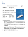
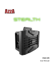
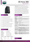
User Manual Model No.: CSAZ‐4000 Table of Contents Chapter 1. Product Introduction Specification…………….……………………………………………………….… 03‐04 Accessories…………………….…………………………………………………….. 05 Chapter 2. Installation Side Panel Disassembly………………………………………………….….…… 06 Motherboard Installation……………………………………………….….….. 07 External 5.25” Device Installation………………………………….….……. 08 External 3.5” Device Installation......................................... 09‐10 External 2.5” HDD Installation………......……………………................ 11 Power Supply Installation........................................................... 12 Fan Installation on the Side Panel ……………….…………..……….. 13‐14 Fan Installation of the Top Unit ……………………….…………..………. 15 Fan Installation of the Bottom Unit ……………………..………... 16‐17 Bottom Fan Installation (Optional) ………………………..…………… 18 Water Cooling Installation………………………………………………… 18‐19 Chapter 3. Other Installation Mini ITX Installation on the Top Unit ……..……………….……….. 20 Second Power Supply Installation on the Top Unit ……………. 21‐22 Front I/O Installation Guide....................................................... 23 Chapter 1. Product Introduction Model: Model Name Fusion 4000 Model Number CSAZ‐4000 Spec: Type ATX Super Full Tower Color Black / Black (inside chassis) Material SECC With Power Supply No Power Supply Locations Rear bottom for Standard ATX power supply Rear top for Mini ITX power supply Motherboard Compatibility XL‐ATX, E‐ATX, Full ATX, Micro ATX, ITX Expansion: External 5.25” Drive Bays 8 External 2.5” Drive Bays 4 x Easy Swap 2.5” slots External 3.5” Drive Bays 6+2 Easy Swap 3.5” slots Internal 3.5” Drive Bays 2 Expansion Slots 10 Front Ports 2 x USB3.0, 1 x USB2.0, HD Audio (Bottom unit) 2 x USB2.0, HD Audio (Top unit) Cooling System: Front 2x120mm blue LED Fans Rear 1x140mm Fan Physical Spec: Dimensions (HxWxD) 780mm x 230mm x 605mm Weight 42 lbs 3
4
Accessories ‐
Screw bag x 1 ‐
Stand with rubber pad x 2 ‐
User Manual x 1 Standoff Screw for Screw for Screw for HDD for M/B 3.5” HDD 2.5” HDD and M/B 4.75H‐6#*6.5H 6*5KM 3*5KM 6#*5B‐C 15PCS 32PCS Screw for Power Supply Thumb Screw 6#6HW‐TC 8PCS Cable Tie L80mm 10PCS 19PCS 5PCS Top unit I/O Membrane cover 1PC 5
8PCS Top unit Top unit power supply fan cover cover M4*10 32PCS Screw 1PC 1PC Chapter 2. Installation Guide Side Panel Disassembly
1. To take off the side panel of the bottom unit, remove the thumb screws from the back of the case, then pull the side panel toward the back to remove it. 2.
To place the side panel back, align the side panel with the hook holes and slide the panel toward the front, then secure the panel with the screws.
3.
To open the side panel of the top unit, push the two indented handgrips inward to release the door. 6
Motherboard Installation 1.
Install the I/O panel that comes with your motherboard package. 2.
Aim at the holes on the motherboard, and secure the standoffs on the motherboard tray.
3.
Align the holes of motherboard with the motherboard tray. Then secure the motherboard with the provided screws. NOTE: Instructions on CPU, RAM and any peripheral installations are not included in this manual. Please refer to your motherboard and/or other manuals for related mounting instructions and troubleshooting. 7
External 5.25” Device Installation 1.
From the interior of the case, use a firm device of your choice to push the 5.25” drive bay cover out. 2. Place the 5.25” device into the drive bay.
3.
Match the ODD drive holes with the drive cage. Then turn the knob clockwise to secure the drive cage. 8
External 3.5” Device Installation 1.
Pull the right side of the front panel gently to open the door. 2.
Remove the hard drive tray by pushing the tray tab to the right to release the hard drive tray. 9
3. Install hard drive by placing each individually into the hard drive tray. Secure each from the bottom of tray with the provided screws.
4. Place the tray back into to the case and lock it in place by pushing the tray in. The rear of the hard drive will connect to the backplane.
5.
Find the 4‐pin Molex on the power supply and connect it to the backplane. Connect the backplane to the motherboard using the SATA cable provided by your motherboard package. 10
External 2.5” Hard Drive / SSD Installation
1. Remove the 2.5” SSD hard drive tray by pushing the tray tab to the right to release the tray.
2.
Place 2.5” SSD hard drive into the hard drive box. Close the box. 3.
Slide the 2.5” SSD hard drive box to the end of drive cage. 11
Power Supply Installation 1. Place the power supply in its proper location and secure it with the provided screws.
2.
Simply route the cables behind the motherboard tray and secure them with the provided cable tie. 3.
To optimize performance it is recommended that the washable dust filter underneath the power supply be cleaned on a regular basis. Simply pull out the dust filter, rinse with water, and slide it back after the dust filter is dried. 12
Fan Installation Fan Installation on the Side Panel 1.
Take out the dust filter from the side panel. 2.
Unscrew these three screws from the back of the side panel. 3.
Pull the plastic cover backward to remove the cover 13
4.
Install the fan on the inside of the side panel and secure it from the outside of the panel with the provided screws. 5.
Up to two 120mm or two 140mm or one 230mm (in both directions) fans can be installed on the left side panel. 6.
Pull out the washable dust filter from the side panel for regular cleaning. 14
Fan Installation of the Top Unit 1.
Remove the thumb screws in the back, slide the top panel toward the front to open the top panel. 2.
Install fans on the top and secure with the provided screws. 3.
Up to four 120mm or three 140mm or two 230mm fans can be installed in the top unit. 15
Top Fan Installation of the Bottom Unit 1.
Push the two indented handgrips inward to release the door. 2. Remove screws as stated in circle. 16
3.
Remove the HDD cage 4.
Pulling the top unit backward to remove it. 5.
Install the top fan on the bottom unit with the provided screws. 6.
Up to three 120mm or two 140mm or one 230mm fan on the top of the bottom unit can be installed. 17
Bottom Fan Installation (optional) 1.
Turn the case upside down and install the fan in the base of the case. 2.
Up to two 120mm or one 140mm or one 230mm fans can be installed on the bottom. Water Cooling Installation 1.
To install an external water cooling system, use the pre‐drilled holes located in the back to connect the tubes. 18
2.
A 360 mm radiator may be installed on the top of the bottom unit using the pre‐drilled screw holes. 3.
A 480mm radiator may be installed on the top of the top unit using pre‐drilled screw holes. 19
Chapter 3. Other Installation The full tower comes with three different rear panels to meet the user’s various needs of users. Mini ITX Installation on the Top Unit 1.
Install the I/O panel that comes with your motherboard package. 2. Install the power supply and the motherboard with the provided screws. 20
Second Power Supply Installation on the Top Unit 1.
Unscrew and remove the rear panel from the back of the case. 2.
From the accessory box locate the proper panel for the second power supply and place the round rubber cover on it. 3.
Install the proper panel in the rear using the provided screws. 4.
Install the power supply in the top unit. 21
5.
To install the second power supply, a special power converter cable is required. 22
Front I/O Installation Guide
The unit comes with two sets of front ports: Front I/O ports for top unit
Front I/O ports for bottom unit
Please refer to the following illustration of front I/O connector and your motherboard user manual. I/O Connector
23