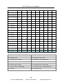
1
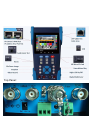
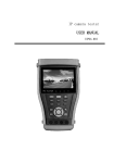
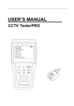
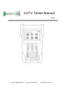
CCTV Tester Manual V2.10 Lo-Call 1890 866 900 www.cctvireland.ie [email protected] Top Panel: Thank you for purchasing the CCTV security tester. Please read the manual before using the CCTV tester and use properly. For using the CCTV tester safely, please first read the「Safety Information」carefully in the manual. The manual should be kept well in case of reference. Keep the S/N label for after-sale service within warranty period. Product without S/N label will be charged for repair service. If there is any question or problem while using the CCTV tester, or damages occurred on the product, please contact our technical Department. Lo-Call 1890 866 900 www.cctvireland.ie [email protected] Content 1、Safety information .............................................................................................................................1 2、Introduction .......................................................................................................................................2 2.1 General ....................................................................................................................................2 2.2 Features ...................................................................................................................................3 2.3 Function ..................................................................................................................................4 2.3.1 Video signal testing....................................................................................................4 2.3.2 Video signal level test ................................................................................................4 2.3.3 PTZ controller ............................................................................................................4 2.3.4 Enhanced Color bar generator ....................................................................................4 2.3.5 DC12V 1A output power ...........................................................................................5 2.3.6 Audio testing..............................................................................................................5 2.3.7 Cable tester ................................................................................................................5 2.3.8 PTZ controller ............................................................................................................5 2.3.9 PTZ address scanning ................................................................................................5 2.3.10 Image magnification(10xZoom) .........................................................................5 2.3.11 Video snapshot .........................................................................................................5 2.3.12 Video record ............................................................................................................5 2.3.13 Video playback ........................................................................................................6 2.3.14 Cable scan (optional function refer to the last page).................................................6 2.3.15 Port flicker ...............................................................................................................6 2.3.16 IP address scan .........................................................................................................6 2.3.17 Link monitor ............................................................................................................6 2.3.18 PING test .................................................................................................................6 2.3.19 POE tester ................................................................................................................6 2.3.20 Digital multimeter (optional function refer to the last page) ..................................6 2.3.21 Optical Power Meter (optional function refer to the last page) .................................7 2.3.22 TDR Break-point and short-circuit measurement (optional function refer to the last page) ...................................................................................................................................7 Lo-Call 1890 866 900 www.cctvireland.ie [email protected] 2.3.23 Visual fault detector (optional function refer to the last page) ..................................7 2.3.24 LED lamp.................................................................................................................7 2.3.25 F1、F2 User-defined shortcut keys ..........................................................................7 2.4 Accessories..............................................................................................................................8 2.5 Front Panel ..............................................................................................................................9 3、Operation .........................................................................................................................................13 3.1 Installing the Battery .............................................................................................................13 3.2 Instrument connection ...........................................................................................................14 3.3 OSD Menu ............................................................................................................................14 3.3.1 PTZ controller ..........................................................................................................15 3.3.2 Color-bar generator ..................................................................................................18 3.3.3 Video setting ............................................................................................................20 3.3.4 PTZ address search ..................................................................................................20 3.3.5 10x zoom image display and Video out ...................................................................21 3.3.6 Photograph ...............................................................................................................22 3.3.7 Video record ............................................................................................................22 3.3.8 Record playback.......................................................................................................22 3.3.9 Cable Scan(optional)...........................................................................................23 3.3.10 PING Test ..............................................................................................................24 3.3.11 Cable tester ............................................................................................................25 3.3.12 Port flicker .............................................................................................................25 3.3.13 Link monitor ..........................................................................................................26 3.3.14 IP address scan .......................................................................................................27 3.3.15 PoE tester ...............................................................................................................27 3.3.16 Digital Multimeter(optional) .............................................................................28 3.3.17 Optical Power Meter(optional)..........................................................................36 3.3.18 Visual Fault Locator(optional) ..........................................................................37 3.3.19 TDR Tester(optional) ........................................................................................37 3.3.20 Data monitor ..........................................................................................................39 Lo-Call 1890 866 900 www.cctvireland.ie [email protected] 3.3.21 Time setting ...........................................................................................................39 3.3.22 Device setting ........................................................................................................40 3.3.23 USB .......................................................................................................................41 3.4 DC12V 1A power output.......................................................................................................41 3.5 Audio input test .....................................................................................................................42 3.6 LED lamp ..............................................................................................................................42 4、Specifications ..................................................................................................................................42 4.1 General Specifications ...........................................................................................................42 4.2 Multimeter specifications: .....................................................................................................45 4.3 Optical power meter specifications........................................................................................48 4.4 Optional models ....................................................................................................................48 Lo-Call 1890 866 900 www.cctvireland.ie [email protected] CCTV Tester User’s Manual 1、Safety information Notice The tester is intended to use in compliance with the local rules of the electrical usage and avoid to apply at the places which are inapplicable for the use of electrics such as hospital, gas station etc. To prevent the functional decline or failure, the product should not be sprinkled or damped. The exposed part of the tester should not be touched by the dust and liquid. During transportation and use, it is highly recommended to avoid the violent collision and vibration of the tester, lest damaging components and causing failure. Don’t leave the tester alone while charging and recharging. If the battery is found severely hot, the tester should be powered off from the electric source at once. The tester should not be charged over 8 hours. Don’t use the tester where the humidity is high. Once the tester is damp, power off immediately and move away other connected cables. The tester should not be used in the environment with the flammable gas. Do not disassemble the instrument since no component inside can be repaired by the user. If the disassembly is necessary indeed, please contact with the technician of our company. The instrument should not be used under the environment with strong electromagnetic interference. Don’t touch the tester with wet hands or waterish things. Don’t use the detergent to clean and the dry cloth is suggested to use. If the dirt is not easy to remove, the soft cloth with water or neutral detergent can be used. But the cloth should be tweaked sufficiently. About digital multimeter Before using, you must select the right input jack, function and range. Never exceed the protection limit values indicated in specifications for each range of measurement. When the meter is linked to a measurement circuit, do not touch unused terminals. Do not measure voltage if the voltage on the terminals exceeds 660V above earth ground. 1 Lo-Call 1890 866 900 www.cctvireland.ie [email protected] CCTV Tester User’s Manual At the manual range, when the value scale to be measured is unknown beforehand, set the range selector at the highest position. Always be careful when working with voltages above 60V DC or 40V AC, keep fingers behind the probe barriers while measuring. Never connect the meter with any voltage source while the function switch is in the current, resistance, capacitance, diode, continuity, otherwise it will damage the meter. Never perform capacitance measurements unless the capacitor to be measured has been discharged fully. Never measure any of resistance, capacitance, diode or continuity measurements on live circuits. 2、Introduction 2.1 General The new CCTV tester is developed for the On-Site installation and maintenance of IP camera,analog camera and network device, with Video display ,PTZ control, DC12v output power ,Audio test, Color generator,RS 485 Data searching and Cable testing, which are the same to the previous models. The new developed functions include POE power supply testing, PING testing, IP address scan, Video screen shot , Video record, Image magnification , Port flicker, Cable search , LED lamp etc. The new tester also has built in TDR cable testing, which is specialized designed for BNC cable testing in the security monitoring system. This function can accurately measure BNC cable and network cable’s break point and short-circuit location. The new tester designed with easy operation and portability makes it simple for a cctv technician or installer to install and maintain CCTV systems, improving work efficiency by reducing time in the field. 2 Lo-Call 1890 866 900 www.cctvireland.ie [email protected] CCTV Tester User’s Manual 2.2 Features English , Chinese and other languages optional 3.5”TFT-LCD, 480(RGB)x320 LED Lamp,easy to operate at night Micro SD card moveable User-defined shortcut keys(F1 and F2) LCD screen brightness/contrast/color Saturation adjustable Automatically adapts and displays the video format of NTSC/PAL 10xzoom,video image can be magnified to view the details, easy to use Video record and playback Snapshot and save the current image as JPG file in the SD card PING testing,test IP camera or other network devices’ ethernet port whether work normally, and the IP address whether right IP address scan, quickly search the IP address for the connected IP camera and other network devices POE voltage measurement,test the PoE switch’s voltage to IP cameras, wireless AP device and other PD devices Device Port flicker,easy to find the connected PoE switch port by sending special signals, the connected PoE port will flicker at special frequency. Link monitor; check the setting IP address whether occupied. TDR break point and short – circuit measurement( BNC cable, network cable etc) PTZ address scan, search up the ID of PTZ camera. Network cable and Telephone cable testing, display the sequence of connection and the NO of the LAN cable Support RS232/RS485/RS422,Rate 600 ~ 115200bps adjustable Multi-protocol. Supports more than thirty PTZ protocols. Such as PELCO-P, PELCO-D, SAMSUNG PTZ protocol analysis, control protocol command displays to check RS485 transmission whether is normal, easy to find the fault device 3 Lo-Call 1890 866 900 www.cctvireland.ie [email protected] CCTV Tester User’s Manual PTZ control. Pan/tilts the P/T unit, zooms in/out the lens, adjusts the focus, aperture and sets and the preset position DC12V 1A power output for camera Audio input test, test the audio signal from pickup devices Visual fault locator , to test fiber’s bending and breakage Lithium Ion Polymer Battery .The device employs advanced power control and protection circuit. The device is high power-efficient, energy saving and environmental protection. It can last 11 hours for normal use after charging for 4 -5 hours 2.3 Function 2.3.1 Video signal testing The new cctv tester ,built-in high definition 3.5”LCD-TFT 480(RGB)x320 full-view display screen, easy and directly displays the camera image quality Support PAL/NTSC LCD screen brightness/Contrast/Color Saturation adjustable. Suitable for field construction and maintenance work 2.3.2 Video signal level test Test video signal strength attenuation, longer video signal cable will cause the image to be dim, and reduce the image dynamic range, video signal is too strong, it will cause the virtual shadow, and reduce the sharpness of the image. It also can real-display the video level value, if out of range, notices will be display in the screen. 2.3.3 PTZ controller Display the input video images. Pan/tilt the P/T unit and zoom in/ out the image. Setup the controlling parameters like protocol, communication port, baud rate, PTZ ID, pan/tilt speed; set and call preset position. 2.3.4 Enhanced Color bar generator Video Generating, the PAL/NTSC multi-system color bar video generator (Eight-system switchable, transmit/receive eight-system colorful imagines). By receiving the video color bar to test the video channel whether transmit normally. And judge whether the color is different, because of the 4 Lo-Call 1890 866 900 www.cctvireland.ie [email protected] CCTV Tester User’s Manual transmission loss or interference, it suitable for Video transmission of the field tests, such as optical video transmitter and receiver, video cable etc. The new function color bar can test the image whether shift. The color bar (red, green, blue, white, black) test the monitor whether have white or black dot etc. 2.3.5 DC12V 1A output power Power the camera with DC12V (1A) power output from the tester. It is helpful for demo and testing when the power supply is not available. 2.3.6 Audio testing Test the audio input from pickup devices. Connect the tester and pickup device with the audio cable. 2.3.7 Cable tester Test LAN cable or telephone cable. Connect LAN cable or telephone cable with the CCTV tester and cable tester. And then the connecting status, cable type and the sequence of wires will be displayed, as well as the serial number of the cable tester kit. 2.3.8 PTZ controller Search the Control protocol code from Multifunction keyboard or DVR by RS485 /RS232 interface, test the PTZ control command data whether received anomaly and RS485/RS232 data transmission. Screen displays 16 hexadecimal codes such as PELCO-P:A0 00(Add) xx xxxxxx AF xx PELCO-D:FF 01(Add)xx xxxxxxxx 2.3.9 PTZ address scanning Search up the ID of PTZ camera. Help the engineer search the speed dome address quickly. 2.3.10 Image magnification(10xZoom) Set image 10x zoom, can view and display the details by 1x、2x、3x、4x、5x、6x - 10X zoom in the monitor and tester. 2.3.11 Video snapshot Capture the video image and save the current video frames as JPEG file 2.3.12 Video record Record and save the current video in the SD card 5 Lo-Call 1890 866 900 www.cctvireland.ie [email protected] CCTV Tester User’s Manual 2.3.13 Video playback Video image and record files are saved in the SD card. Storage file directory can be created according to the date 2.3.14 Cable scan (optional function refer to the last page) Send the specific signal, easy to find the connected cable. 2.3.15 Port flicker The tester will send special signals to make the connected POE port flicker at special frequency, which will enable the installers to easily and quickly find the connected ethernet cable. This function can prevent mistakenly insertion or disconnection non-corresponding cable to artificially interrupt network connection. 2.3.16 IP address scan In digital IP surveillance applications, if IP camera’s IP address is not clear or forgotten; the device cannot be used .IP address scan can quickly search the connected IP camera or other network device’s IP address. 2.3.17 Link monitor To add an IP camera or other network device to the current network group, the new IP address must not be occupied, otherwise it will cause IP conflicts and stop the equipment normal working. Link monitor can check if the new setting IP address is occupied. 2.3.18 PING test PING is the most conventional network debugging tools; It is used for testing if the connected IP camera or other network equipment’s ethernet port is working normally and the IP address is correct. 2.3.19 POE tester It can test the PoE voltage when the POE switch is supplying the POE power to IP camera. It can clearly display the power+ and power- on the ethernet cable pins, each cable pin’s voltage and the failure connection of cable pin series numbers. 2.3.20 Digital multimeter (optional function refer to the last page) CCTV Tester built in highly stable and reliable 33/4 digit (6600) digital multimeter. It is used for the DC and AC voltage measurement , AC and DC current measurement , Resistance measurement, Continuity test, Diode measurements, Capacitance measurement, Auto/Manual measuring range 6 Lo-Call 1890 866 900 www.cctvireland.ie [email protected] CCTV Tester User’s Manual switching, relative value measurement and locking . It is easy operation and professionally accurate. 2.3.21 Optical Power Meter (optional function refer to the last page) The New tester adopts the most advanced handheld instrument specific integrated chip , achieve ultra-low power operation, with the 3.5 TFT-LCD High-definition screen display ,five wavelength calibration points 1625nm、1550nm 、 1490nm 、 1310nm 、 1300nm 、 850nm.Linear or nonlinear optical power display, it can measure the optical power value, and also be used for Relative measurement of optical fiber link loss. It is necessary tool for fibre-optic communication, cable television system and security system maintenance. 2.3.22 TDR break-point and short-circuit measurement (optional function refer to the last page) New function: TDR cable testing, accurately measure BNC cable, network cable, control cable break-point and short-circuits location. It improves working efficiency. 2.3.23 Visual fault locator (optional function refer to the last page) Visual Fault Locator with 650nm wavelength can emit red laser sources to test multi-mode and single mode fiber’s bending and breakage, and Continuous light-emitting and 1HZ, 2Hz modulating light output. It is indispensable tool in fiber project constructing, fiber net-work maintaining, optical component manufacture and research. 2.3.24 LED lamp It is useful for the Engineer to install and maintain security system at night. LED On/Off pressing button, easy operation. 2.3.25 F1、F2 User-defined shortcut keys The user-defined shortcut key is designed for improving the efficiency for the engineer, anytime press, easy to operate. 7 Lo-Call 1890 866 900 www.cctvireland.ie [email protected] CCTV Tester User’s Manual 2.4 Accessories 1). CCTV tester 2). Power Supply DC5V 1.2~1.5A(with USB cable) 3). Cable test box or wire tracer 4). Lithium Ion Polymer Battery(3.7V DC 3000mAh ) 5). BNC cable 6). RS485 cable 7) SC, ST connector (Only for the optical power meter models) 8) Multimeter test leads one pair of red and black (only for the Multimeter models) 9). Power cable 10). Audio cable 11). TDR alligator clamp( only for TDR models) 12). Safety cord 13). Tool bag 14). Instruction Manual 8 Lo-Call 1890 866 900 www.cctvireland.ie [email protected] CCTV Tester User’s Manual 2.5 Front Panel 9 Lo-Call 1890 866 900 www.cctvireland.ie [email protected] CCTV Tester User’s Manual 1 2 OSD menu The charge indicator: it lights red while the battery is being charged. As the charging is complete, the indicator turns off automatically 3 The data-transmission indicator: it lights red while the data is being transmitted 4 The data-reception indicator: it lights red while the data is being received 5 The power indicator: it lights green while the tester is powered on 6 Set key, press it to enter sub-menu to set the parameters of functions 7 8 9 10 Press more than 2 seconds, turn on or off the device ,short press to turn on or off the menu display Confirm/Open : Confirm the setting of parameters;open or enlarge the aperture Return/Close : Return or cancel while setting parameters of the menu, close or decrease the aperture Upward: Select the item which will be set or add the value of the parameter. Tilt the PTZ upward 11 User-defined key(User setting function, the default is “PTZ controller”) 12 LED Lamp 13 14 15 16 Rightward,Enter the sub-menu or select the parameter whose value will be changed. Add the value of the parameter. Pan the PTZ right Voltage, current, resistance and capacitance measuring, continuity testing, diode testing Downward: Select the item which will be set or reduce the value of the parameter. Tilt the PTZ downward Leftward: Enter the sub-menu or select the parameter whose value will be changed. Reduce the value of the parameter. Pan the PTZ left 17 Video record 18 Snapshot(capture video image) 19 10xzoom the image display and video out 10 Lo-Call 1890 866 900 www.cctvireland.ie [email protected] CCTV Tester User’s Manual 20 WIDE: zoom in the image 21 Near focus: Focus the image nearby 22 Far focus: Focus the image faraway 23 Menu key 24 TELE: zoom out the image 11 Lo-Call 1890 866 900 www.cctvireland.ie [email protected] CCTV Tester User’s Manual With TDR testing Without TDR testing 26 Video input (BNC input interface): Inputs the video 27 Video output (BNC output interface): Outputs the video 28 TDR cable break point and short circuit test 29 Output DC12V1A power, for provisional DC test supply 30 RS232 interface: RS232 communication for the PTZ 31 LED lamp 32 RS485/422 Interface: RS485/RS422 communication for the PTZ 33 Network cable /Telephone cable interface test 34 USB data /charge interface 35 Moveable MicroSD card 36 Ethernet power supply output/Network testing interface 37 Ethernet power supply input interface 38 Audio input: test the pickup and other audio equipments on the front-end 39 Reset the default settings of parameters 40 Optical power meter interface (Optional) 41 Visual Fault Locator with 650nm wavelength, can emit red laser sources to test multi-mode and single mode fiber’s bending and breakage 12 Lo-Call 1890 866 900 www.cctvireland.ie [email protected] CCTV Tester User’s Manual 3、Operation 3.1 Installing the Battery The tester has built-in lithium ion polymer rechargeable battery. The battery cable inside battery cabin should be disconnected for safety during transportation! Prior to the use of the instrument, the battery cables inside the battery cabin should be well connected. Usually it doesn’t need to disconnect the cable at the normal use Pressing key continuously can power on or off the tester. Notice:Pls use the original adaptor and connected cable of the device At the first time of use, the batteries should be completely exhausted and then recharged for 4 or 5 hours. The Charge Indicator lights red when charging the battery, the charge indicator turns off automatically when the charging is completed. Notice: When the Charge Indicator turns off, the battery is approximately 90% charged. The charging time can be extended for about 1 hour and the charging time within 8 hours will not damage the battery. Press the RESET key at the left of the instrument to restore the default settings when the instrument works abnormally. Multimeter: the red and black multimeter pen must insert the corresponding port. 13 Lo-Call 1890 866 900 www.cctvireland.ie [email protected] CCTV Tester User’s Manual 3.2 Instrument connection ⑴. The camera or dome video output is connected to CCTV Tester VIDEO IN,the image display on the tester . ⑵. CCTV Tester “VIDEO OUT” interface connect to the Video input of monitor and optical video transmitter and receiver, the image display on the tester and monitor ⑶. Connect the camera or the speed dome RS485 controller cable to the tester RS485 interface ,(Note positive and negative connection of the cable).Support RS232 PTZ controller ,connect the RS232cable to RS232 interface of the tester 3.3 OSD Menu Press the key Press the key again to turn on. to turn off, also can set time off Enter the menu ,choose one function to enter , short press 14 Lo-Call 1890 866 900 www.cctvireland.ie [email protected] CCTV Tester User’s Manual the key , Close the menu bar at the top of the screen, full screen display, press it again, turn it on Press the key to enter the menu,Continuously press quickly switch to the desired function menu . Anytime, press this key to enter the menu. In various functional mode, press the key When turn it on, press the key Press the key key Set the various parameter values , to enter the function menu, continuously press the , select different function, and press the key to switch the menu,the square to enter. ,different square means different interface Press the key select the different function icon, then press the key First page menu Second page menu to enter Third page menu 3.3.1 PTZ controller Display the input video images. Press the key to enter the menus and set Parameter .Pan/tilt the P/T unit and zoom in/ out the image. Setup the controlling parameters like protocol, communication port, baud rate, PTZ ID, pan/tilt speed; set and call preset position. Display the input image; press the key closed the top menu, display full screen image Enter PTZ controller, if no video input, the screen display “No video”. 15 Lo-Call 1890 866 900 www.cctvireland.ie [email protected] CCTV Tester User’s Manual PTZ controller parameter setting In the “PTZ CONTROLLER ”mode (as shown above ),press the key to enter the parameter setting . press the key Press the key 、 or , move the yellow cursor to select , change the parameter values. Then press the key to save and return. If no change, Press the key to return setting, and then press the key return the PTZ controller function. A. Protocol Use the up and down arrow keys to move the yellow cursor to the “protocol ” , set corresponding Protocol ,Support more than thirty PTZ protocols. Such as Pelco-D、Samsung、Yaan、 LiLin、CSR600、Panasonic、Sony-EVI etc. B. Port Move the yellow cursor to “port” Select the communication port for the PTZ camera controlling (RS232/422/485) C. Baud Move the yellow cursor to “Baud”, Select the baud rate according to baud rate of the PTZ camera.(600/1200/2400/4800/9600/19200/57600/115200bps) D. Address Set the ID according the ID of PTZ camera (0~254), the setting address data must be consistent the speed dome address. E. Pan speed: Set the pan speed of PTZ camera (0~63) F. Tilt speed: Set the tilt speed of PTZ camera (0~63) G. Set preset position (Set PS) Move the yellow cursor to “SET PS ”,set and save preset position number(1~128),Press the key to accelerate the value changing, then press the key H. to save, Press to quit. Call the preset position (Go ps) Move the yellow cursor to “Set PS”, then Setup preset position (1~128), 16 Lo-Call 1890 866 900 www.cctvireland.ie [email protected] CCTV Tester User’s Manual Press key or Press the key to accelerate the value changing. to complete preset position setting or press return key to to quit. Call some special preset number,can call the dome camera menu Check and set the protocols, address, interface and baud, must be the same as the dome camera, then can test and control. After setting the parameter, the tester can control the PTZ and lens Press the key to control the PTZ direction of rotation Press the key or to switch on or turn off the aperture. Press the key or ,adjust the focus manually Press the key or ,manually adjust the zoom 1) Set and go PS Set PS A. P/T/Z the camera to desired position. B. Press the key to enter the PTZ controller submenu. Press the key yellow cursor to “Set PS”, Press the key Press enter key Move the to select the preset position number. to complete preset position setting or preset return the key to give up set position setting. Go PS: Call the preset position. (1~128) The PTZ camera will go to the desired preset position. In “PTZ Controller” mode,Press the key to t enter PTZ controller submenu. Press the key Move the yellow cursor to “GO ps” , to select the preset position number. Then press the enter key to complete preset position setting or preset RETURN key to give up preset position setting. Camera moves to the preset position immediately, Lens zoom, focus and iris is automatically changed to the preset parameters, preset the camera image displayed on the monitor. Tips:Preset position setting is saved in the domes. (Preset position can be set depending on the dome) 17 Lo-Call 1890 866 900 www.cctvireland.ie [email protected] CCTV Tester User’s Manual 2) Menu of dome Different dome camera factory control system be used different preset position, pls refer to the dome camera manual. The provided dome camera enter the the menu by calling preset position 64,this example is for reference only a. Press the key b.Press the key c. Press the key to enter PTZ controller submenu , select preset position 64 Enter the main menu of the PTZ camera OSD Menu of Dome (For Reference only) After Calling the dome camera menu , Users can select different function through the arrow keys, the dome camera menu operation refer to the manual. 3.3.2 Color-bar generator Press the key to enter the menu Press the key to select the bar , and then press the key to enter 18 Lo-Call 1890 866 900 www.cctvireland.ie [email protected] CCTV Tester User’s Manual Test the Color- bar generator, support global PAL / NTSC standard color bar of different output formats Press the key or ,move the cursor to “Format”、“LCD display select”、“Type ”.select “Format”,the tester send the color bars from the “Video out” port .Press the key the video output formats. when select“LCD”,press the key Press the or or to switching switching the display content. to turn off the menu, sending or receiving image to display full screen;Press it again; display the Color – bar generator menu. In the “ color bar generator” mode, output different standard color bar and received by “Video IN ” port,Display the video input and output . This feature is available for test monitoring transmission channels, such as optical video transmitter and receiver, video cables, etc. the “Video out ” port connect the sending port of the optical video transmitter , the “Video in ” port connect the receiving port Image receiving:connect the Video OUT port to the Video in port, Video generator send the color bars, to choose the direction key change the display select for the “Video input”, The screen is in the image receiving state, if cannot receive the image ,the screen display “NO VIDEO ”, if received , display the sending and receiving consistent color bar. Application: A . When maintain the dome camera, send the image to the monitoring center, If the monitoring center can receive the image, it means that the Video transmission channel normal, in addition, the monitor center can judge the image quality through the received color bar. B .Test the optical video transmitter and Video cable, sending and receiving color bar by itself, check the transmission equipment or cable whether normal. c.Send the pure color bar (such as white and black color),to test the monitor whether has bright or black dots D .Send video signal image,test received image whether shift. 19 Lo-Call 1890 866 900 www.cctvireland.ie [email protected] CCTV Tester User’s Manual 3.3.3 Video setting Press to the menu , press to enter. LCD brightness, contrast, color saturation can be adjusted. The CCTV tester auto displays the format (PAL/NTSC) of video input, and analysis the input video signal level. The Video Level should be within the indicated range. Levels that are too low will result in a dim picture with reduced dynamic range. A Video Level that is too high will result in washed out pictures with decreased. Depending on the type of camera connected to the CCTV tester, the Video “Format ” will automatically change between NTSC and PAL, and the Video Level will automatically change between IRE (Institute of Radio Engineers) and mV. NTSC signals measured in IRE units, PAL signals measured in mV. 3.3.4 PTZ address search Press to select , press to enter. Note:Please isolate the PTZ camera with other PTZ cameras before searching up. Otherwise all the PTZ cameras in the same system will pan at the same time. 20 Lo-Call 1890 866 900 www.cctvireland.ie [email protected] CCTV Tester User’s Manual Press to select , and then press search”, press function to enter (as follow picture). to select ON or OFF, then Press Select to “Address to save. The PTZ address search displays in the main menu. (Note:This function need to reset after each time turn off. ) Press key to set: protocol, communication port, communication rate, make them the same as PTZ camera. Press button, the tester will search up the ID quickly and continuously. When the ID is searched, the PTZ camera will pan right. At this time, please press Press the key to stop searching up. manual single-step decreasing button, the tester will search up the ID step by step. When the ID is searched, the PTZ camera will stop panning. Press button, the tester will search up the ID quickly and continuously. When the ID is searched, the PTZ camera will pan left. At this time, please press to stop searching up. Press manual single-step incremental button,the tester will search up the ID step by step. When the ID is searched, the PTZ camera will stop panning. Manual search address: Press or to search the address gradually, the image will flash when the address found. Press the direction control button Press button to adjust Speed Dome Camera. to quit. 3.3.5 10x zoom image display and Video out While video input, press to 10x zoom, and press the button to zoom out the image. Press to see the details. Press to zoom in the image, press to quit. 21 Lo-Call 1890 866 900 www.cctvireland.ie [email protected] CCTV Tester User’s Manual Set image 10x zoom, can view and display the local details by 1x、2x、3x、4x、5x、6x -10X zoom in the monitor and tester. 3.3.6 Photograph While video in, Press the key to save the current video frame in the SD card as JPEG file. Set storage file according to the date, it’s convenient to check .the tester automatically checks whether have SD card when photograph. If no SD card, shown “no SD Card” on the the screen. 3.3.7 Video record While video in, press several seconds, the icon is flicking on the top left, means the video record is under working and saving the video in the SD card as AVI format. Press the flicker icons disappears and stop working. Set storage file according to the date, it’s convenient to check. Note: press the button several seconds, and start to the video record. 3.3.8 Record playback Press to select , press to enter, the latest photograph or video record file display on the screen. As the above picture, the photograph file with the icon on the top right corner. Press , and the video record file with the icon to start and stop video playback and, press to quit. See the above image, the 3/0008 in the image means total 8 screenshot and video file, and the current 22 Lo-Call 1890 866 900 www.cctvireland.ie [email protected] CCTV Tester User’s Manual file is the third. press to quit the latest storage image, Press to choose the files. Then press to shown all the storage files, press to enter the files, press to choose the files. Press to choose the image. 3.3.9 Cable Scan(optional) Connect the cable to the UTP port or the CABLE SCAN (VIDEO OUT) port on the top. Press to select , then press to enter, press to choose the audio type. Turn on the cable scan; use the copper pin to search, the cable with loudest voice means it is connected with the tester. Four Audio types can choose. LED lamp is convenient to work in dark or at night. Press the button (+ - ) to adjust the volume, use two batteries (size AAA) Application It’s convenient for people to find out the other end of the cable in security maintenance and 23 Lo-Call 1890 866 900 www.cctvireland.ie [email protected] CCTV Tester User’s Manual network engineering. While searching BNC cable, connect one port of the alligator clips to the copper core or copper net of the BNC cable, the other one to connect the earth wire (barred windows). Note:The battery of the wire tracer must according to corresponding positive pole + and negative pole -, or damage the tester. Note:While receive the audio signal from the tester, it will be influenced by the other signal and make some noise. 3.3.10 PING Test Connect the cable to the LAN port, press to select , and then press to adjust the IP address, Packet Size, Timeout, TTL, Count. Press to enter. Press to adjust the parameter. If IP camera or other ethernet equipment is not connected to the tester, “connect fail ” display on the screen. The sending and receiving packet amount is 0, the success rate is 0%. Press to restart the Ping testing after the IP equipment is well connected. If the IP address is correct, the sending and receiving packet amount will be consistent; the success rate will be 100%. Application PING testing is the most conventional network debugging tools. It is used for testing if the connected IP camera or other network 24 Lo-Call 1890 866 900 www.cctvireland.ie [email protected] CCTV Tester User’s Manual equipment’s ethernet port is working normally and the IP address is correct. It’s normal that the first data packet will be lost when start the PING testing. 3.3.11 Cable tester Press to menu , press to enter. Test LAN cable or telephone cable. Connect LAN cable or telephone cable with the CCTV tester and cable tester. And then the connecting status, cable type and the sequence of wires will be displayed, as well as the serial number of the cable tester kit. Note: if No cable tester box, it can be used with the wire tracker 3.3.12 Port flicker Press to select , and then press to enter. Press to start, the tester send the signal, to make the connected PoE port flicker at special frequency. Press to stop, and press to quit. 25 Lo-Call 1890 866 900 www.cctvireland.ie [email protected] CCTV Tester User’s Manual If the tester and PoE port are not well connected, there won’t be any change on the PoE port. Application: The tester will send special signals to make the connected PoE port flicker at special frequency, which will enable the installers to easily and quickly find the connected ethernet cable. This function can prevent mistakenly insertion or disconnection non-corresponding cable to artificially interrupt network connection. 3.3.13 Link monitor Press to select , and then press to enter. Add the IP address, make sure the network segment and the setting IP address are consistent, choose “start”, and press to link monitor. If the status is “√”, means the IP address is occupied, if the status is“×”, means the IP address is available Application: Add an IP camera or other network device to the current network group, the new IP address must not be occupied, otherwise it will cause IP conflicts and stop the equipment normal working. Link monitor can check if the new setting IP address is occupied. 26 Lo-Call 1890 866 900 www.cctvireland.ie [email protected] CCTV Tester User’s Manual 3.3.14 IP address scan Connect the cable to the LAN port, press “Set IP”, press to select press to enter. Press to set the local IP address, the network segment and the network devices must be consistent. After setting, move the cursor to “Start”, press to scan the IP camera or other network equipment address. 3.3.15 POE tester Press to to select , and then press to enter. Connect the cable to the power supply equipment’s POE port and the tester’s PSE IN port. Connect IP camera or wireless AP equipment connect tester’s LAN port, the POE voltage and the cable’s pin connection status show on the screen. Note: the Poe power supply equipment( POE Switch, PSE power supply equipment) must be connected to the PSE IN port, the powered device such as IP camera or wireless AP must be connected to the LAN port, then it measure the voltage correctly. PlS do not connect POE power supply port to the UTP/SCAN port, otherwise it will damage the tester. 27 Lo-Call 1890 866 900 www.cctvireland.ie [email protected] CCTV Tester User’s Manual 3.3.16 Digital Multimeter (optional) To press 1) to select , press Function Button: :Auto range :Data hold :Function select 2) to enter :Relative measuring :Manual range SYMBOLS: U:DC Voltage Measuring U~:AC Voltage Measuring A:DC Current Measuring A~:AC Current Measuring Ω:Resistance Measuring :Continuity Testing :Diode Testing AC/DC Auto- range Data hold Relative :Capacitance Measuring Voltage and current measurement state display The Multimeter auto adjust the range by input signal or tested components Hold data Display the relative measurement value measurement Press the key to change display state 10A socket In 10A current measurement state ,indicate use 10A socket Over range The current measurement value over the range, if in the Auto range state, to switch Auto. 28 Lo-Call 1890 866 900 www.cctvireland.ie [email protected] CCTV Tester User’s Manual 3) OPERATING INSTRUCTION A. DC Voltage Measuring WARNING! You can’t input the voltage which more than 660V DC, it’s possible to show higher voltage, but it’s may destroy the inner circuit. Pay attention not to get an electric shock when measuring high voltage. a. Connect the black test lead to the “COM ” jack and the red test lead to the “V/Ω” jack. b. Press to select U, enter the DC voltage measurement. c.Auto range by press key and manual range by press d.Manual range: 0.000V 6.600V range 00.00V 66.00V range 000.0V 660.0V range 000.0mV 660.0mV range B. AC Voltage Measuring WARNING! You can’t input the voltage which more than 660V AC, it’s possible to show higher voltage, but it’s may destroy the inner circuit. Pay attention not to get an electric shock when measuring high voltage. a. Connect the black test lead to the “COM” jack and the red test lead to the “V/Ω” jack. 29 Lo-Call 1890 866 900 www.cctvireland.ie [email protected] CCTV Tester User’s Manual ~ to select U , enter the AC voltage measurement. Auto range by press key b. Press and manual range by press Manual range: 0.000V 6.600V range 00.00V 66.00V range 000.0V 660.0V range 000.0mV 660.0mV range C. DC Current Measuring(only manual range ) WARNING! Shut down the power of the tested circuit, and then connect the meter with the circuit for measurement. a. Connect the black test lead to the “COM ” jack and the red test lead to the “mA” jack for a maximum of 660mA current. For a maximum of 10A, move the red lead to the 10A jack. b. Press to select A, enter the DC current measurement. Manual range by press , only manual range supply. Manual range: 0.000mA 6.6mA range 00.00mA 66.00mA range 000.0mA 660.0mA range 00.00A 10.00A range(use 10A socket) c. Connect test leads in series with the load under measurement. d. You can get reading from LCD. NOTE: When only the figure “OL” is displayed, it indicates over range situation and the higher range has to be selected. When the value scale to be measured is unknown beforehand, set the range selector at the highest 30 Lo-Call 1890 866 900 www.cctvireland.ie [email protected] CCTV Tester User’s Manual position. The maximum current of mA socket is 660mA, over-current will destroy the fuse, and will damage the meter. The maximum current of 10A socket is 10A, over-current will destroy the meter, and will damage the operator. D. AC Current Measuring (Only Manual range) WARNING! Shut down the power of the tested circuit, and then connect the meter with the circuit for measurement. a. Connect the black test lead to the “COM” jack and the red test lead to the“mA” jack for a maximum of 660mA current. For a maximum of 10A, move the red lead to the 10A jack. b. Press ~ to select A , enter the AC current measurement. Manual range by press only manual range supply. Manual range: 0.000mA 6.600mA range 00.00mA 66.00mA range 000.0mA 660.0mA range 00.00A 10.00A range(use 10A socket) c. Connect test leads in series with the load under measurement. d. You can get reading from LCD. NOTE: When only the figure “OL” is displayed, it indicates over range situation and the higher range has to be selected. When the value scale to be measured is unknown beforehand, set the range selector at the highest position. The maximum current of mA socket is 660mA; over-current will destroy the fuse, and will damage 31 Lo-Call 1890 866 900 www.cctvireland.ie [email protected] CCTV Tester User’s Manual the meter. The maximum current of 10A socket is 10A, over-current will destroy the meter, and will damage the operator. In“ AC ” mode, only can input “AC ”, if not, will damage the meter. E. Resistance Measuring WARNING! When measuring in-circuit resistance, be sure the circuit under test has all power removed and that all capacitors have discharged fully. a. Connect the black test lead to the “COM ” jack and the red test lead to the“V/Ω” jack. b. Press to select Ω, enter the Ω measurement. Auto range by press range by press key, and manual . Manual range:(Connect the red lead to black leads, will display the measure range) 000.0Ω 660Ω range 0.000 KΩ 6.600KΩ range 00.00 KΩ 66.00KΩ range 000.0 KΩ 660.0KΩ range 0.000 MΩ 6.600MΩ range 00.00 MΩ 66.00MΩ range c. Connect test leads across the resistance under measurement. d. You can get reading from LCD. NOTE: When only the figure “OL” is displayed, it indicates over range situation and the higher range has to be selected. 32 Lo-Call 1890 866 900 www.cctvireland.ie [email protected] CCTV Tester User’s Manual F. Continuity Testing WARNING! When testing the circuit continuity, be sure that the power of the circuit has been shut down and all capacitors have been discharged fully. a. Connect the black test lead to the “COM” jack and the red test lead to the “V/Ω” b. Press to select jack. , enter the continuity test. c. Connect test leads across two point of the circuit under testing. d. If continuity exists (i.e., resistance less than about 50Ω), built-in buzzer will sound. e. You can get reading from LCD. G. Diode Testing a. Connect the black test lead to the “COM” jack and the red test lead to the “V/Ω” jack.( the red lead anode “+” ) b. Press to select , enter the diode testing. c. Connect test red lead across to the anode, the black lead to the cathode of the diode under testing. d. Connect test red lead across to the cathode, the black lead to the anode of the diode under testing. E .Tested diode,forward voltage low 30mv,there is sound indication ,then can finish the testing quickly without view the screen. F.The capacitance of a capacitor should be tested separately, should not test in the installation of circuit. H. Capacitance Measuring WARNING! To avoid electric shock, be sure the capacitors have been discharged fully before measuring the capacitance of a capacitor. 33 Lo-Call 1890 866 900 www.cctvireland.ie [email protected] CCTV Tester User’s Manual a. Connect the black test lead to the“ COM ” jack and the red test lead to the “V/Ω ” jack. b. Press to select Auto range by press , enter the capacitance measurement. key, and manual range by press Manual range:0.000nF 6.600nF range 00.00nF 66.00nF range 000.0nF 660.0nF range . 0.000uF 6.600μF range 00.00uF 66.00μF range 000.0uF 660.0μF range 0.000mF 6.600mF range 00.00mF 66.00mF range c. Before connect test leads across two sides of the capacitor under measurement, be sure that the capacitor has been discharged fully. d. You can get reading from LCD. Note: a. The capacitance of a capacitor should be tested separately, should not test in the installation of circuit. b. To avoid electric shock, be sure the capacitors have been discharged fully before measuring the ca pacitance of a capacitor. c. While testing the capacitance of a capacitor to 660uF, the Max time will be 6.6 seconds, if the capacitor is leaked or damaged, the data can’t be read. The tester will be normal after disconnecting the capacitor. Manual range and Auto range Press the key to change the value, press the to Auto measurement 34 Lo-Call 1890 866 900 www.cctvireland.ie [email protected] CCTV Tester User’s Manual Data hold Press the key to hold the data, the value is green. Press it again to quit. Relative value measurement Press the key , the tester Auto-save the data, the displayed new measurement and relative value is red color. Press it again to quit The hold function and the relative value be combined use, the display value is yellow The meter protection ⑴ Voltage protection You can’t input the voltage which more than 660V AC, it’s possible to show higher voltage, but it’s may destroy the inner circuit. Resistance、Continuity、Diode、PTC component Protection Wrong input voltage,will Auto enter protection state , It only suitable for short and limit time work. If the input voltage over 600V, will damage the meter. mA current fuse range :250V 1A if the current over the rated range ,fuse will melt to protect the meter .Pls use the same model when change the fuse, Pls opens the battery cover to change. Note: 10A socket without fuse protection, if over the current range Wrong using the 10A socket to measure the voltage, will damage the meter. 35 Lo-Call 1890 866 900 www.cctvireland.ie [email protected] CCTV Tester User’s Manual 3.3.17 Optical Power Meter(optional) Press twice or press and , select press to enter. ⑴ Function: :Data hold :Relative measuring : Wavelength select :mW/dBm units select ⑵ Instruction: A. Press MODE key to select “Optical power meter” B. Absolute power value measurement 1) Set the wavelength via key, the default wavelength is 1310nm. 2) Input the optical fiber to be measured, the power value is displayed in LCD. 3) Linear and nonlinear value of the current optical-fiber power can be displayed by pressing key to change the unit to be mW or dBm. Note:Pls keep the fiber connector and the dust cap be clean, and clean the detector with the special alcohol. Data hold While testing, press to data hold, the data will not change. It’s convenient to read. Press again to quit. Relative power value (optical link loss) measurement 36 Lo-Call 1890 866 900 www.cctvireland.ie [email protected] CCTV Tester User’s Manual 1) Set the wavelength for measurement. 2) Measure the first optical fiber, pressing the key under any display unit, then the current fiber power value is stored as the base reference value. 3) Input another optical fiber to be measured, the relative power value is displayed. The optical power meter displays the end-end loss of the fiber under test; the unit of loss value must be dB. Data hold and Relative measuring use together, the data is yellow while the function is effect. 3.3.18 Visual Fault Locator(optional) Press to select , then press to enter. Insert the fiber to the device’s “VFL” interface, default output power is 10mW and the wavelength is 650nm. Press to adjust pulse mode and stable model 3.3.19 TDR Tester(optional) Note:The testing cable can’t be connected to any equipment, or it will damage the tester. Connect Alligator clip cable to the TDR port, and the cable must connect well before testing, or it will influence the accuracy. Press to select , press to enter. 37 Lo-Call 1890 866 900 www.cctvireland.ie [email protected] CCTV Tester User’s Manual Built-in BNC, network cable, RVV control cable, Telephone line can test. 12 groups user-defined cable can be set. Press to line type interface, press to choose the line type, press to save and start testing. Press to adjust the speed, if select the user-defined cable type, adjust the speed after the calibration. User-defined calibration: Choose the cable 100 meters to 200 meters (more than 50 meters) press to set the user-defined calibration. Press to select user 1 to calibrate, 12 groups user-defined can be set. Press to “Adjust”, press to “Speed” and press length, press to cable type, press to choose the cable style, press to adjust. While display length is the same as the actual to save. It can be used for the same cable after the calibration. Application: The disconnection and short circuit display in the tester, it is more convenient and efficient to repair the faulty cable. Note: The TDR reflect signal could be affected by the cable quality/ cable’s not well connected etc to cause the different TDR measurement. The TDR measurement is for reference only. 38 Lo-Call 1890 866 900 www.cctvireland.ie [email protected] CCTV Tester User’s Manual 3.3.20 Data monitor Press to select Press , press to enter. to choose the baud rate of RS485/RS232; it must be the same as the DVR or the Control keyboard. The DVR or Control keyboard send the code to the tester, if it can be read, the protocol will shown on the upper right, like Pelco D, if not, like P:--Press to empty while the tester receives the code. Though the RS485 port, display the PTZ control code of the multifunctional keyboard or the DVR. Controller can check the status of the RS485 transmission through the code on the display. (The RS485 communication rate must be the same.) Application:Check the RS485 communication states of the video optical transmitter whether normal. Engineer can analyze the protocol and check the data through the displayed code. 3.3.21 Time setting Press to menu , press to enter. 39 Lo-Call 1890 866 900 www.cctvireland.ie [email protected] CCTV Tester User’s Manual Note:Press to set the parameter of the time, press to save. Users need to set the time first, as the time of the photograph and video record is the same as the Time setting. 3.3.22 Device setting Press to menu Press or , press to enter. to choose the item, press to adjust, press to save, press to quit. Auto power off: Setting the time of auto shut-down.(Disable,5,10,…,60) Disable: Disable the “Auto power off” function. 5 means the CCTV will power off after 5 minutes when there is no any operation. Keypad tone: Open or close the beep of pressing keypad. Language: ENGLISH/ CHINESE and other languages Brightness: Setting the brightness of OSD menu and background.(0~7) Address search: off / on Open or close the PTZ address search Menu. Restore factory setting: restore the data of the factory. F1 user-defined keyboard shortcuts: Users can set the function as you like, press press to select, to save. The default value is “ PTZ controller”. F2 user-defined shortcut key is the same setting of the F1 shortcuts keys. The default is “Device setting”. 40 Lo-Call 1890 866 900 www.cctvireland.ie [email protected] CCTV Tester User’s Manual 3.3.23 USB All the photograph files or video record can be uploaded to computer, it’s convenient to check. 3.4 DC12V 1A power output Power the camera with DC12V (1A) power output from the tester. It is helpful for demo and testing where there is no power supply available. Notice a. Don’t input any power into the “DC12/1A OUTPUT” port of the CCTV tester to avoid destroy. b. Don’t output this DC12V/1A power to the power input port of the CCTV tester to avoid destroy. c. When the requirement of the camera is higher than 1A, the CCTV tester will enter protection mode. Disconnect all the connections of the CCTV tester and then connect the CCTV tester with power adaptor to resume the CCTV tester. d. Make sure the the tester is full charged or more than 3 bars, or it will be short circuit. 41 Lo-Call 1890 866 900 www.cctvireland.ie [email protected] CCTV Tester User’s Manual 3.5 Audio input test Test the audio input from pickup devices. Connect the tester and pickup device with the audio cable. 3.6 LED lamp With the LED lamp can work in the evening or in the dark. Turn on the tester, press for several seconds, and the LED lamp turn on, press , and turn it off. Note: Laser is harmful, so especially, you must protect your eyes. When the LD working, please don’t let your eyes exposure to laser. 4、Specifications 4.1 General Specifications Video Test Signal mode NTSC/PAL (Auto adapt) Display 3.5 inch digital TFT-LCD ,480(RGB)x 320 resolution LCD adjustment Brightness, Contrast, Saturation adjustable Video IN/OUT 1 channel BNC Input & 1 channel Output Video Output Mode 1.0 Vp-p Video Level test 42 Lo-Call 1890 866 900 www.cctvireland.ie [email protected] CCTV Tester User’s Manual Level test Video signals measured in IRE or mV PTZ controller Communication PTZ Protocol Baud Rate Support RS232 and RS485 Compatible with more than 30 protocols such as PELCO-D/P, Samsung, Panasonic, Lilin, Yaan, etc. 600,1200,2400,4800,9600,19200,57600,115200bps Video Signal Generation Color bar generator Output one channel PAL/NTSC color bar video signal for testing monitor or video cable.(red, green ,blue, white and black color ) UTP Cable tester UTP cable test Test UTP cable connection status and display in the screen. Read the number of the test box. DC12V 1A power output DC12V power output Output DC12V1A power for camera Audio input test Audio input test test the pickup and other audio equipments on the front-end RS485 data analysis Data Monitor Captures and analyzes the command data from controlling device 10x Zoom Image Image 10x zoom 10x zoom image display and video out Photograph、Video record, Record playback Photograph snapshot and save the current image as JPG file Video record Video record and storage the file Record playback To view the storage file in the SD card 43 Lo-Call 1890 866 900 www.cctvireland.ie [email protected] CCTV Tester User’s Manual Port flicker Port flicker Find the connected POE port quickly. IP scan、Link monitor、PING test IP scan Find out the connected IP camera or the other network equipment IP address quickly. Link monitor Check the IP address whether is occupied PING testing Test IP camera or Ethernet port of the other network equipment whether work normally, and check the IP address Cable scan Cable scan Search the cable by the audio signal PoE tester PoE tester Display the power supply voltage and cable connection states Digital Multimeter AC/DC Voltage 0-660V auto/manual range, the min resolution is 0.1mV AC/DC current 660.0uA , 6.600mA, 66.00mA , 660.0mA, 10.00A Resistance 660.0Ω, 6.600kΩ, 66.00kΩ, 660.0kΩ, 6.600MΩ, 66.00MΩ Capacitance 6.6nf~66000uF, the min resolution is 1pf Diode 0~2V forward voltage, the min resolution is 1mV Data hold Hold and display the measured value Relative measurement Display the relative power value Continuity testing Built-in buzzer will sound, if resistance is lower than 50 Ω Testing speed 3 times/ seconds Data range -6600~+6600 Optical power meter Calibrated Wavelength(nm) 850/1300/1310/1490/1550/1625nm Power range(dBm) -70~+10dBm Sensitivity(nW) 0.001nW Connector type FC/PC 44 Lo-Call 1890 866 900 www.cctvireland.ie [email protected] CCTV Tester User’s Manual Data hold Hold and display the measured value Relative measurement Display the relative power value Visual fault locator Visual fault locator Test fiber’s bending and breakage ( SM and MM fiber) TDR Tester TDR Tester breakpoint and short circuit measurement(BNC cable, telephone cable) POWER Power Adapter DC 5V(1.5A) Battery Built-in 3.7V Lithium polymer battery ,3000mAh Rechargeable After charging 3-4 hour, working time lasts 11 hours Low Consumption Energy saving technology, the battery icon real-time display Parameter Operation setting English/Chinese and other languages OSD menu Auto off 5-60 (mins) Keytone On/Off General Working Temperature -10℃ ~+50℃ Working Humidity 30%~ 90% Dimension/Weight 194mm x 112mm x 48mm / 540g 4.2 Multimeter specifications: Counts:-6600~+6600 Conversion rate: 3 times/s Current modes for clamp meter with ZERO function Isolation: the Multimeter connector must be isolated with the other connector. 45 Lo-Call 1890 866 900 www.cctvireland.ie [email protected] CCTV Tester User’s Manual DC Voltage Range Accuracy 660mV (Manual range) 6.600V 0.1mV ±(0.3%+4) 66.00V Resolution 660.0V 1mV 10mV 100mV AC Voltage Range 660.0mV (Manual range) Accuracy ±(1.5%+6) 6.600V Resolution 0.1mV 1mV 66.00V ±(0.8%+6) 660.0V 10mV 100mV DC Current Range Accuracy 6.600mA 66.00mA 1uA ±(0.5%+3) 660.0mA 10.00A Resolution 10uA 100uA ±(1%+5) 10mA AC Current Range Accuracy 6.600mA 66.00mA 1uA ±(0.5%+3) 660.0mA 10.00A Resolution 10uA 100uA ±(1%+5) 10mA 46 Lo-Call 1890 866 900 www.cctvireland.ie [email protected] CCTV Tester User’s Manual Resistance Range Accuracy 660.0Ω Resolution 0.1Ω ±(0.8%+5) 6.600KΩ 1Ω 66.00KΩ 10Ω ±(0.8%+2) 660.0KΩ 100Ω 6.600MΩ 1KΩ 66MΩ ±(1.2%+5) 10KΩ Continuity Range 660.0Ω Resolution 0.1Ω Function The measurement value less 30Ω±3Ω,the tester will sound Diode Range Resolution Function Schottky diode:0.15~0.25V 2.0V 1mV rectifier diode:0.6~1.0V triode PN junction:0.5~0.8V Capacitance Range Accuracy Resolution 6.600nF ±(0.5%+20) 1pF 66.00nF ±(3.5%+8) 10pF 47 Lo-Call 1890 866 900 www.cctvireland.ie [email protected] CCTV Tester User’s Manual 660.0nF 100pF 6.600μF 1nF 66.00μF 10nF 660.0μF 100nF 6.600mF 1μF ±(5%+8) 66.00mF 10μF 4.3 Optical power meter specifications -70~+10dBm Measure Range(dBm) 850nm、1300nm、1310nm、1490nm、1550nm、1625nm Wavelength(nm) Detector InGaAs <±3%dB(-10dBm,22 ℃) <±5%dB(full range,22 Uncertainly Linear:0.1% ; Nonlinear:0.01dBm Display Resolution Operating Temperature( Storage Temperature ( ℃) -10~+50 ℃) -20~+70 ℃) Connector type FC/PC 4.4 Optional models function model A B C D E F G H I 3.5 HVGA LCD ✔ ✔ ✔ ✔ ✔ ✔ ✔ ✔ ✔ Image enlarge(1-10 times) ✔ ✔ ✔ ✔ ✔ ✔ ✔ ✔ ✔ photograph ✔ ✔ ✔ ✔ ✔ ✔ ✔ ✔ ✔ Video record ✔ ✔ ✔ ✔ ✔ ✔ ✔ ✔ ✔ Record playback ✔ ✔ ✔ ✔ ✔ ✔ ✔ ✔ ✔ 48 Lo-Call 1890 866 900 www.cctvireland.ie [email protected] CCTV Tester User’s Manual SD card ✔ ✔ ✔ ✔ ✔ ✔ ✔ ✔ ✔ Color-bar generator ✔ ✔ ✔ ✔ ✔ ✔ ✔ ✔ ✔ Video signal level test ✔ ✔ ✔ ✔ ✔ ✔ ✔ ✔ ✔ Protocol capture and display ✔ ✔ ✔ ✔ ✔ ✔ ✔ ✔ ✔ PTZ address search ✔ ✔ ✔ ✔ ✔ ✔ ✔ ✔ ✔ DC 12V/1A power output ✔ ✔ ✔ ✔ ✔ ✔ ✔ ✔ ✔ Audio test ✔ ✔ ✔ ✔ ✔ ✔ ✔ ✔ ✔ LED Lamp ✔ ✔ ✔ ✔ ✔ ✔ ✔ ✔ ✔ PING test ✔ ✔ ✔ ✔ ✔ ✔ ✔ ✔ ✔ ✔ ✔ ✔ ✔ ✔ ✔ ✔ ✔ ✔ POE tester ✔ ✔ ✔ ✔ ✔ ✔ ✔ ✔ ✔ Link monitor ✔ ✔ ✔ ✔ ✔ ✔ ✔ ✔ ✔ IP address scan ✔ ✔ ✔ ✔ ✔ ✔ ✔ ✔ ✔ UTP cable tester ✔ ✔ ✔ ✔ ✔ ✔ ✔ ✔ ✔ ✔ ✔ ✔ ✔ ✔ ✔ Port flicker Wire tracker Digital multimeter ✔ ✔ Optical power meter ✔ ✔ ✔ ✔ Visual fault locator TDR Tester A+T B+T C+T D+T E+T F+T ✔ ✔ ✔ G+T H+T I+T A: Base Model A+T: Base Model+TDR B: Add Wire tracker B+T: Add Wire tracker+TDR C: Add Wire tracker +DMM C+T: Add Wire tracker +DMM+TDR D: Add OPM D+T: Add OPM+TDR E: Add Wire tracker +OPM E+T: Add Wire tracker +OPM+TDR F: Add Wire tracker +OPM+DMM F+T: Add Wire tracker +OPM+DMM+TDR G: Add RLS G+T: Add RLS+TDR 49 Lo-Call 1890 866 900 www.cctvireland.ie [email protected] CCTV Tester User’s Manual H: Add wire tracker +RLS H+T: Add wire tracker +RLS+TDR I: Add wire tracker +RLS +DMM I+T: Add wire tracker +RLS +DMM+TDR The data above is only for reference and any change of them will not be informed in advance. For more detailed technical inquiries, please feel free to call the Technical Department of our company. 50 Lo-Call 1890 866 900 www.cctvireland.ie [email protected]