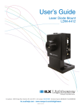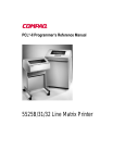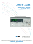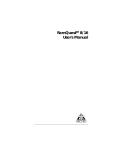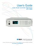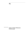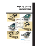
1
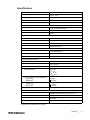
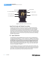
User’s Guide Laser Diode Mount LDM-4409 ILX Lightwave Corporation · P. O. Box 6310 · Bozeman, MT, U.S.A. 59771 · U.S. & Canada: 1-800-459-9459 · International Inquiries: 406-556-2481 · Fax 406-586-9405 ilx.custhelp.com · www.ilxlightwave.com 70038602 October 2009 TA B L E O F C O N T E N T S TABLE OF CONTENTS Safety Information and the Manual . . . . . . . . . . . . . . . . . . . . . . . . . . . . . . . . . iii General Safety Considerations . . . . . . . . . . . . . . . . . . . . . . . . . . . . . . . . . . . . iii Safety Marking Symbols . . . . . . . . . . . . . . . . . . . . . . . . . . . . . . . . . . . . . . . . . iv Comments, Suggestions, and Problems . . . . . . . . . . . . . . . . . . . . . . . . . . . . vi Chapter 1 Introduction and Specifications Product Overview . . . . . . . . . . . . . . . . . . . . . . . . . . . . . . . . . . . . . . . . . . . . . . . . 1 Specifications . . . . . . . . . . . . . . . . . . . . . . . . . . . . . . . . . . . . . . . . . . . . . . . . . . . 3 Chapter 2 Operation LDM-4409 Mount Electrical Connections . . . . . . . . . . . . . . . . . . . . . . . . . . . . . 5 Laser Diode Anode and Cathode Connections . . . . . . . . . . . . . . . . . . . . . . . 6 P1 - Laser Connection . . . . . . . . . . . . . . . . . . . . . . . . . . . . . . . . . . . . . . . . . . 6 P2 - TEC Connection . . . . . . . . . . . . . . . . . . . . . . . . . . . . . . . . . . . . . . . . . . . 8 P3 - Fan Power Jack . . . . . . . . . . . . . . . . . . . . . . . . . . . . . . . . . . . . . . . . . . . 8 P4 - Fan Power Banana Jacks . . . . . . . . . . . . . . . . . . . . . . . . . . . . . . . . . . . . 9 P5 - Chassis Ground . . . . . . . . . . . . . . . . . . . . . . . . . . . . . . . . . . . . . . . . . . . 9 Loading Devices into the LDM-4409 . . . . . . . . . . . . . . . . . . . . . . . . . . . . . . . . 10 Post Mounting the LDM-4409 . . . . . . . . . . . . . . . . . . . . . . . . . . . . . . . . . . . . . . 11 Chapter 3 Maintenance Chapter 4 Safety 07_09 LDM-4409 i TA B L E O F C O N T E N T S ii LDM-4409 SAFETY AND WARRANTY INFORMATION The Safety and Warranty Information section provides details about cautionary symbols used in the manual, safety markings used on the instrument, and information about the Warranty including Customer Service contact information. Safety Information and the Manual Throughout this manual, you will see the words Caution and Warning indicating potentially dangerous or hazardous situations which, if not avoided, could result in death, serious or minor injury, or damage to the product. Specifically: Caution indicates a potentially hazardous situation which can result in minor or moderate injury or damage to the product or equipment. Warning indicates a potentially dangerous situation which can result in serious injury or death. WARNING Visible and/or invisible laser radiation. Avoid direct exposure to the beam. General Safety Considerations If any of the following conditions exist, or are even suspected, do not use the instrument until safe operation can be verified by trained service personnel: • Visible damage • Severe transport stress • Prolonged storage under adverse conditions • Failure to perform intended measurements or functions If necessary, return the instrument to ILX Lightwave, or authorized local ILX Lightwave distributor, for service or repair to ensure that safety features are maintained (see the contact information on page vi). All instruments returned to ILX Lightwave are required to have a Return Authorization Number assigned by an official representative of ILX Lightwave Corporation. See Returning an Instrument on page v for more information. LDM-4409 iii SAFETY SYMBOLS SAFETY SYMBOLS This section describes the safety symbols and classifications. Technical specifications including electrical ratings and weight are included within the manual. See the Table of Contents to locate the specifications and other product information. The following classifications are standard across all ILX Lightwave products: • Indoor use only • Ordinary Protection: This product is NOT protected against the harmful ingress of moisture. • Class I Equipment (grounded type) • Mains supply voltage fluctuations are not to exceed ±10% of the nominal supply voltage. • Pollution Degree II • Installation (overvoltage) Category II for transient overvoltages • Maximum Relative Humidity: <80% RH, non-condensing • Operating temperature range of 0 °C to 40 °C • Storage and transportation temperature of –40 °C to 70 °C • This equipment is suitable for continuous operation. Safety Marking Symbols This section provides a description of the safety marking symbols that appear on the instrument. These symbols provide information about potentially dangerous situations which can result in death, injury, or damage to the instrument and other components. Caution, refer to manual Earth ground Terminal Alternating current Visible and/or invisible laser radiation Caution, risk of electric shock Protective Conductor Terminal Caution, hot surface Frame or chassis Terminal On: In position of a bistable push control. The slash (I) only denotes that mains are on. or (I) iv LDM-4409 Off: Out position of a bistable push control. The circle (O) only denotes that mains are off. or (O) WA R R A N T Y WARRANTY ILX LIGHTWAVE CORPORATION warrants this instrument to be free from defects in material and workmanship for a period of one year from date of shipment. During the warranty period, ILX will repair or replace the unit, at our option, without charge. Limitations This warranty does not apply to fuses, lamps, defects caused by abuse, modifications, or to use of the product for which it was not intended. This warranty is in lieu of all other warranties, expressed or implied, including any implied warranty of merchantability or fitness for any particular purpose. ILX Lightwave Corporation shall not be liable for any incidental, special, or consequential damages. If a problem occurs, please contact ILX Lightwave Corporation with the instrument's serial number, and thoroughly describe the nature of the problem. Returning an Instrument If an instrument is to be shipped to ILX Lightwave for repair or service, be sure to: 1 Obtain a Return Authorization number (RA) from ILX Customer Service. 2 Attach a tag to the instrument identifying the owner and indicating the required service or repair. Include the instrument serial number. 3 Attach the anti-static protective caps that were shipped with the instrument and place the instrument in a protective anti-static bag. 4 Place the instrument in the original packing container with at least 3 inches (7.5 cm) of compressible packaging material. Shipping damage is not covered by this warranty. 5 Secure the packing box with fiber reinforced strapping tape or metal bands. 6 Send the instrument, transportation pre-paid, to ILX Lightwave. Clearly write the return authorization number on the outside of the box and on the shipping paperwork. ILX Lightwave recommends you insure the shipment. If the original shipping container is not available, place your instrument in a container with at least 3 inches (7.5 cm) of compressible packaging material on all sides. Repairs are made and the instrument returned transportation pre-paid. Repairs are warranted for the remainder of the original warranty or for 90 days, whichever is greater. Claims for Shipping Damage When you receive the instrument, inspect it immediately for any damage or shortages on the packing list. If the instrument is damaged, file a claim with the carrier. The factory will supply you with a quotation for estimated costs of repair. You must negotiate and settle with the carrier for the amount of damage. 07_09 LDM-4409 v WA R R A N T Y Comments, Suggestions, and Problems To ensure that you get the most out of your ILX Lightwave product, we ask that you direct any product operation or service related questions or comments to ILX Lightwave Customer Support. You may contact us in whatever way is most convenient: Phone . . . . . . . . . . . . . . . . . . . . . . . . . . . (800) 459-9459 or (406) 586-1244 Fax . . . . . . . . . . . . . . . . . . . . . . . . . . . . . . . . . . . . . . . . . . . . . (406) 586-9405 On the web at: . . . . . . . . . . . . . . . . . . . . . . . . . . . . . . . . . . . . ilx.custhelp.com Or mail to: ILX Lightwave Corporation P. O. Box 6310 Bozeman, Montana, U.S.A 59771 www.ilxlightwave.com When you contact us, please have the following information: Model Number: Serial Number: End-user Name: Company: Phone: Fax: Description of what is connected to the ILX Lightwave instrument: Description of the problem: If ILX Lightwave determines that a return to the factory is necessary, you will be issued a Return Authorization (RA) number. Please mark this number on the outside of the shipping box. You or your shipping service are responsible for any shipping damage when returning the instrument to ILX Lightwave; ILX recommends you insure the shipment. If the original shipping container is not available, place your instrument in a container with at least 3 inches (7.5 cm) of compressible packaging material on all sides. vi LDM-4409 CHAPTER 1 INTRODUCTION AND SPECIFICATIONS This manual describes the LDM-4409 C-Mount Laser Diode Mount and related accessories and options and explains their operation. This chapter provides an overview of the LDM-4409 and contains general information and specifications important in its use. You should read the entire manual to familiarize yourself with the operation of your LDM-4409 Laser Diode Mount before installing laser diodes. In particular, you should read the section on Electrical Connections before installing a laser diode. The information contained in this section is necessary to provide correct electrical connection to your particular laser. Product Overview The LDM-4409 C-Mount Laser Diode Mount provides a convenient solution for fixturing C-mount laser diodes during testing or evaluation. The LDM-4409 accepts most C-mount packages and provides active temperature control for temperature testing. Unobstructed access to the front of the C-mount device allows for measurements of highly divergent beams and easy integration into laboratory or manufacturing optical measurement set-ups. Thermal resistance between the diode and the mount's hot plate was minimized to ensure consistent L-I-V data taken on the device under test. The 4409 comes standard on a pedestal mount for more stability, however a standard optical table post-mount option is available through ILX Lightwave. The mount is quick to set up with connectors for laser current and temperature control, a DC input for forced air cooling of the heat sink, and a ground post for laser diode static protection during insertion and removal. C-mount lasers are simply inserted into the spring-loaded clamp on the front of the mount, once seated against the hot plate, a thumb-wheel actuated contact connects to the laser's flying lead. For improved thermal resistance, a hold down screw through the center of the laser can be used in conjunction with the clamp. LDM-4409 1 CHAPTER 1 INTRODUCTION AND SPECIFICATIONS Product Overview The LDM-4409 mount allows direct interfacing to all of ILX Lightwave's current sources and temperature controllers through standard ILX current and temperature control cables. This feature gives you the flexibility to select an appropriate ILX current source or temperature controller for your particular application. 2 LDM-4409 Specifications Laser Packages C-mount laser diode Package Width 6.35 +/- 1mm Flying Lead Height 7.75 +/- 1mm Package Depth 2.18mm to 3.16mm 1 Clearance Zone : 1mm Laser Clamping Spring Loaded Clamp: 3.7 lbf across laser package Screw Clamp: #2-56 x 3/16” socket head cap screw Torque: 3 in-lb. Input Connectors Laser Diode Current Hybrid D-sub, female, 7W2 Case Temperature Control Hybrid D-sub, male, 7W2 Fan Female banana jacks; DC power jack Ground Female banana jack Laser Diode Connections Anode Laser mounting plate Cathode Isolated clamp Maximum Laser Current: 10A Case Temperature Control Maximum Thermal Load2 25W Temperature Control Range3 +10oC to 85oC Sensor Type 10 k NTC thermistor TE Module Ratings Qmax 78W Imax 7.4A Vmax 16.4V DTmax 70oC Laser to Hot Plate Thermal Resistance 000Clamp Only: 000With Screw4: <3oC/W <0.75oC/W Thermal Resistance Repeatability 000Clamp Only: 000With Screw4: +0.2oC/W +0.06oC/W Fan Supply 5V DC @ 0.5A General Size (H x W x D) 152mm x 102 mm x 78.7mm (6” x 4” x 3.1”) Weight 1.27 kg (2.8 lbs) Thread for Post Mount #8-32 UNC Regulatory Compliance RoHS All specifications verified with 5V fan operating. LDM-4409 3 CHAPTER 1 INTRODUCTION AND SPECIFICATIONS Specifications 1. From the front of the laser package. 2. Forced convection (fan operating) 3. 25W head load @ 25oC ambient temperature. Maximum control temperature determined by TEC operating range. 4. Screw must be tightened to specified torque. Our goal is to make the best laser diode instrumentation available anywhere. To achieve this, we need your ideas and comments on ways we can improve our products. We invite you to contact us at any time with your suggestions. 4 LDM-4409 CHAPTER 2 OPERATION This chapter describes the electrical connections and operation of the LDM-4409. Laser diodes are extremely susceptible to damage caused by electrostatic discharge and surge currents. To avoid early failure or damage to the device, workers and workbenches must be grounded at all times when handling or working with laser diodes. Do not exceed the specified current settings of the laser. Excessive drive current may cause laser failure. LDM-4409 Mount Electrical Connections There are five connections on the LDM-4409. See Figure 2.1 LDM-4409 Laser Mount Connections. P1 and P2 connect ILX Lightwave curent source and temperature controllers to the 4409. P3 and P4 provide power to the integrated cooling fan. P5 is a ground connection. LDM-4409 5 CHAPTER 2 OPERATION LDM-4409 Mount Electrical Connections Laser Anode Laser Cathode P4 - Fan Power Banana Jacks P2 - TECConnection P3 - Fan Power Jack P1 - LASER Connection P5 - Chassis Ground Figure 2.1 LDM-4409 Laser Mount Connections Laser Diode Anode and Cathode Connections The laser diode anode (C-mount base) connection is made through the laser mounting plate on the front of the mount. Attaching the laser to the laser plate connects the laser drive anode to the laser diode anode. The laser’s cathode connection (C-mount flying lead) is made through a thumb-wheel actuated clamp on the front of the mount. The clamp is isolated from the mount. The laser plate is floating relative to the case of the mount to prevent any transients from affecting the laser during operation. P1 - Laser Connection The LDM-4409 is interchangeable with most current sources and temperature controllers manufactured by ILX. The P1 connector is a standard 7W2 connector compatible with most ILX Lightwave LDX current sources. For lower power lasers, the LDX-3545 or LDX-3565 current sources with a CC-305H interconnect cable can be used. For higher power lasers, the LDX-32420 10A/20A current source with a CC-320 interconnect cable can be used. The CC-308H can also be used with LDX-36000 units producing less than 10A. The pin-out for the 4409’s LAS connector is illustrated in Figure 2.2. If an ILX Lightwave current source is used with the system interlock feature, the interlock connections are available at pins 1 and 2 of the current source connector (see Figure 2.4). With the ILX Lightwave interlock feature enabled, the interlock pins must be connected before current can flow from the source. 6 LDM-4409 CONNECTOR TYPE: 7W2 FEMALE HYBRID D Figure 2.2 LDM-4409 Laser Cable Pin Out Proper shielding of the current source and temperature controller signals is necessary to ensure proper noise-free performance. This is accomplished by grounding the shield on the interconnect cables to the controller and not to the mount. Four-wire laser forward voltage measurement is available on the LDX-32420 through pins 4 and 5 of the 7W2 connector and with the use of the CC-320 interconnect cable. Voltage measurement is available on some lower power ILX current sources and controllers. No additional connections for voltage measurement are required with these instruments. For higher power lasers where the LDX-36000 is required, 4-wire voltage measurement will only be available if additional wires are added from the CC-368S measurement output terminal box to the 9-pin sense connector on the LDX-36000. Other ILX current sources with 4wire voltage measurement do not required special wiring if using standard cables. If it is necessary to measure the current of your laser during operation, follow these steps: 1 NEVER connect an ammeter in series with the laser circuit. 2 Place a known resistance in series with the laser diode circuit. Then measure the voltage across the resistor. Calculate the current by using Ohm’s Law (I = E/R). 3 NEVER turn the voltmeter on or off, or change the voltage measurement range, while current is flowing to the laser. These actions could result in the destruction of your laser diode. LDM-4409 7 CHAPTER 2 OPERATION LDM-4409 Mount Electrical Connections P2 - TEC Connection The LDM-4409 contains a solid-state thermoelectric (TE) module located between the laser plate and the heat sink. The module will heat or cool the laser diode to between +10oC and 85oC when it is supplied by current from an appropriate thermoelectric temperature controller and the cooling fan is on. Feedback from a thermistor embedded in the laser plate measures the temperature of the laser plate and is used for temperature feedback to the thermoelectric temperature controller. The P2 connector is a standard 7W2 D-sub connector compatible with ILX Lightwave thermoelectric temperature controllers. For lower power lasers, the LDT-5525B or LDT-5545B controller can be used with a CC-501HT interconnect cable . For higher power lasers, the LDT-5948 or LDT-5980 thermoelectric temperature controller can be used with a CC-596H interconnect cable. The pin-out for the 4409’s TEC connector is illustrated in Figure 2.3. Figure 2.3 LDM-4409 TEC Cable Pin Out Thermal resistance, measured in oC/W, between the laser package and the laser plate results in a temperature difference between the laser plate and laser diode especially with higher power devices. The laser plate is gold plated for better thermal conductivity. Caution must be used when placing a laser diode in the mount and removing it not to scratch the surface between the laser and the laser plate. Scratches and contamination of the surface will degrade the thermal performance of the mount resulting in an increase of the thermal resistance between the laser and laser plate. Thermal resistance can increase to 5oC/W or greater with a damaged or contaminated surface. P3 - Fan Power Jack An auxiliary fan mounted on the bottom of the LDM-4409 mount provides additional cooling when driving higher current devices. The fan can be powered through one of two methods; a user provided bench power supply or a 2.5W AC adapter. The fan power requirements are 5 volts at 0.5 amps. 8 LDM-4409 OPERATION LDM-4409 Mount Electrical Connections CHAPTER 2 A 5 volt power supply can be purchased from ILX, P/N 800127. The power supply is pre-wired with a 2.1 mm power plug to mate to the fan power jack located on the side of the mount. See Figure 2.4. P4 - Fan Power Banana Jacks P3 - Fan Power Jack P5 - Chassis Ground Figure 2.4 LDM-4409 Fan Power and Ground Connections P4 - Fan Power Banana Jacks The auxiliary fan can also be driven from a user provided bench supply connected through the banana jacks located on the side of the mount. See Figure 2.4. The power supply should be connected as follows: 1 Red Banana Jack - +5 Volts, 0.5 Amps 2 Black Banana Jack - Common P5 - Chassis Ground A ground point is provided to allow the user to connect ESD protective straps to the mount. See Figure 2.4. 07_09 LDM-4409 9 CHAPTER OPERATION Loading Devices into the LDM-4409 2 Loading Devices into the LDM-4409 Thumb Wheel Flying Lead Clamp Optional Screw Clamp Contact Bar Hold Down Clamp Figure 2.5 LDM-4409 Device Mounting Figure 2.5 illustrates a C-mount device loaded into the LDM-4409 mount. The device can be loaded through the following method. 10 LDM-4409 1 Open the flying lead clamp by turning the thumb wheel located on the front of the mount to the left. Open the clamp to provide sufficient room between the contact bar and the clamp to allow the flying lead to be placed in the gap. 2 Press the bottom of the device hold down clamp to allow insertion of a device into the top of the hold down clamp. 3 Using tweezers, carefully insert the device into the top of the hold down clamp being careful to insert the flying lead between the contact bar and the flying lead clamp. 4 Once the device is fully seated, release the bottom of the hold down clamp. The clamp will provide adequate pressure to secure the device to the cold plate. 5 A #2-56 socket head cap screw can be used to secure the device to the mount for improving thermal resistance. It is recommented to torque the screw to at least 3 in/lb. 6 Close the flying lead clamp by turning the thumb wheel located on the front of the mount to the right until the clamp securely presses the flying lead onto the contact bar. 7 Reverse the procedure to remove the device from the LDM-4409. OPERATION Post Mounting the LDM-4409 CHAPTER 2 Post Mounting the LDM-4409 The LDM-4409 comes standard with a pedestal and base mount design to be mounted to a standard optical table. The pedestal and base can be removed from the bottom of the LDM-4409 by removing two screws located on the bottom of the base with a 3/16” allen head wrench. A #8-32 threaded hole is provided on the LDM-4409 to allow the user to install a post. 07_09 LDM-4409 11 CHAPTER 12 LDM-4409 2 OPERATION Post Mounting the LDM-4409 CHAPTER 3 MAINTENANCE No maintenance procedures are required for the LDM-4409 other than an occasional cleaning, as needed, to remove any accumulated dust or dirt from the cooling fins on the heat sink and the hot plate. If the mount is not in use with a laser inserted, the flying lead thumb-wheel contact should be in the closed position up against the insulated contact and a thermal pad or equivalent inserted between the spring loaded clamp and the mount hot plate. Insert plastic anti-static covers over the 9-pin laser current and temperature control connectors. LDM-4409 13 CHAPTER 14 LDM-4409 3 MAINTENANCE CHAPTER 4 SAFETY Laser diodes used with the LDM-4409 Laser Diode Mount may emit infrared radiation which is invisible to the human eye. Extreme care must be taken to prevent the beam from being viewed either directly or through external optics or mirrors. Remove rings, jewelry, and other reflective materials when working with lasers. WARNING Viewing of emissions from the laser may cause eye damage. Use of protective goggles is recommended when operating these lasers. Use of controls or adjustments or performance of procedures other than those specified herein may result in hazardous radiation exposure. This product conforms to all applicable DHHS regulations 21 CFR Subchapter J, at the date of manufacture. LDM-4409 15 CHAPTER 16 LDM-4409 4 SAFETY