1
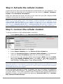
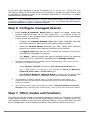
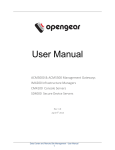
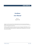
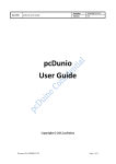
ACM5508-‐2-‐GS-‐I Quick Start Guide Thank you for purchasing the ACM5508-2-GS-I management gateway. This Quick Start walks you through installation, configuration & local operation. More details are available in the User Manual, which can be downloaded from: http://opengear.com/documentation Step 1 Check kit contents ACM5508-2-GS-I appliance. External rack and DIN rail mount tabs. Green terminal block and 3G antenna. UTP cables. Straight (319014) & crossover (319015) DB9F-RJ45s. Straight (319016) DB9MRJ45. Quick Start. 12VDC power pack. Step 2 Connect the hardware Ø Attach rubber feet to base and/or attach the desired mounting tab Ø Screw the 3G antenna on to the main Cell (M) connector, if you have purchased a diversity or GPS antenna, screw it on to Cell (A) Ø Connect the Ethernet LAN 1 port to your primary network, connect LAN 2 to a secondary network, e.g. external management switch or VLAN Ø Connect your serial devices to the SERIAL 1-8 ports, connect your USB devices to the two USB ports Ø Plug in the green screw terminal block and attach external sensors and DIO Refer to the ACM5500-I Addendum for details on RS422/485 and DIO. Note: Ø Apply power, the appliance may be powered by connecting: o o o o o The included power pack to the 12VDC barrel socket An external 9 – 24V AC source to the 12VDC barrel socket An external +9 – 30V DC source to DC PWR and GND on the green terminal block The optional DC power converter input to +/- 36V – 72V DC, and output to the 12vDC barrel socket The optional C13/C14 power adapter to the 12VDC barrel socket ACM5508-‐2-‐GS-‐I Quick Start (520072-‐Rev 1.0) Page 1 Note: When the PWR status LED is lit steadily and the H/B (heartbeat) is flashing, the appliance is ready for activation. Step 3 Set up appliance networking The appliance’s default IP address is 192.168.0.1 (subnet mask 255.255.255.0). With a web browser on any computer that is connected to the appliance via LAN: Ø Enter https://192.168.0.1 into the address bar Ø Log in using the default system user name root and the default password default, a Welcome screen listing the basic configuration steps is displayed Note: The computer must have an IP address in the same network range (192.168.0.x) as the appliance. Alternatively, you can use the arping command to set the IP address (refer to the User Manual or online Knowledge Base FAQ for details). The appliance also has DHCP client enabled by default. It will automatically accept any network IP address assigned by any DHCP server on your network, and will then respond at both 192.168.0.1 and its DHCP address. Ø Select Serial & Network: Users & Groups and Edit the Root User. Enter and confirm a new Password and click Apply Ø Select System: IP then Network Interface (LAN 1) and check DHCP or Static for Configuration Method The appliance’s second Ethernet port is inactive by default. To activate: Ø Select Management LAN Interface (LAN 2) and uncheck Disable Ø Enter the IP Address and Subnet Mask for this segment of the Management LAN (leaving Gateway and DNS fields blank) – refer to the User Manual if you wish to enable the DHCP server or change default firewall/router settings Note: The appliance’s firewall determines which protocols and services can be used to access which ports and devices. By default only HTTPS and SSH access is enabled to the appliance itself. Use the Service Access menu on System: Services to change settings for the appliance itself (and for connected serial ports). Similarly using the Forwarding & Network menu on System: Firewall you can permit IP access between devices on Network Interface and Management LAN. ACM5508-‐2-‐GS-‐I Quick Start (520072-‐Rev 1.0) Page 2 ACM5508-‐2-‐GS-‐I Quick Start (520072-‐Rev 1.0) Page 3 Step 4 Activate the cellular modem Contact Sprint and give them the ESN (Electronic Serial Number) for your appliance. The ESN is located on underside of the appliance and also shown on Status: Statistics: Cellular under Hardware Information). Select your data plan and Sprint will send you an email with your MSL, MDN and MSID numbers. At this point the modem is good to go. Note: Obtaining a public static IP address – Sprint provides an option that can be added on to certain plans, which will allocate a publicly reachable IP address. If you require direct remote access to your appliance without the use of Call Home or an outbound VPN, then you will need this feature. To add this to your Data/Voice+Data plan, request a Standard Static IP or a Reserved Static IP address be added to your line. An additional monthly fee will apply. For more information visit: http://sprint.com Step 5 Connect the cellular modem To set up an Always-on Out-of-Band cellular connection: Ø Select System: Dial then the Internal Cellular Modem tab Ø Select Enable Dial-Out and click Apply Ø Select Status: Statistics then the Failover & Out-of-Band tab Ø Verify the Connection Status of Internal Cellular Modem is Connected and note your allocated IP Address (take note if it’s a private IP address) Ø At any time you may view the cellular signal strength (RSSI) from the Cellular tab of the Status: Statistics page – an RSSI of -100 dBm and less is unacceptable coverage, -99 to -90 is weak coverage, -89 to -70 is medium to high coverage, -69 and greater is very strong coverage Note: Cellular modem status is also shown by the WWAN LED. The LED is off when the modem is not powered or being reset. When powered, the LED turns on and flashes briefly every 5 sec while searching for service. Once configured and connected, the WWAN LED blinks more rapidly. If you have been allocated a public IP address, you can now access the appliance’s HTTPS and SSH services directly. The public IP may be static or dynamic, depending on your plan options. If you have a dynamic public IP address that changes each time the appliance connects, you may configure the appliance’s Dynamic DNS client in System: Dial, Internal Cellular Modem. ACM5508-‐2-‐GS-‐I Quick Start (520072-‐Rev 1.0) Page 4 ACM5508-‐2-‐GS-‐I Quick Start (520072-‐Rev 1.0) Page 5 If you have been allocated a private IP address (i.e. in the 10.x.x.x, 172.16-31.x.x or 192.168.x.x range), direct remote access is not possible. Instead, use Call Home or VPN to establish an outbound tunnel to an Opengear Lighthouse or VPN server, to enable remote access over the tunnel. Note: For a detailed overview of remote access alternatives to an appliance with a private IP address, refer to the Knowledge Base FAQ article Does my site need a public IP address for OOB or Failover access? Step 6 Configure managed devices Ø Ø Select Serial & Network: Serial Port to display the labels, modes and protocol options currently set for each serial port – to configure a port for remote access to the managed device’s serial console (refer to the User Manual if other modes are required): o Configure the Common Settings (Baud Rate, Parity, Data Bits, Stop Bits and Flow Control) to match those of the device being controlled o Select the Console Server protocols (e.g. SSH, Telnet, Web Terminal) that are to be used for the network connection to this console o A Logging Level may also be set to specify the direction and level of information to be logged for that port o Click Apply – device consoles can now be accessed using your preferred client (e.g. PuTTY, SecureCRT, OpenSSH) and in Manage: Devices Network managed devices connected via the Management LAN (LAN 2) can be accessed in a number of ways: o Select System: Firewall and define a Port/Protocol Forward rule o Use a VPN client to connect to the appliance’s Serial & Network: OpenVPN, IPsec VPN or PPTP VPN server o Add Serial & Network: Network Hosts to permit your preferred SSH client or SDT Connector to establish an SSH port forward to the device Ø The appliance’s default firewall policy is a NAT gateway configuration, so network devices are permitted outbound WAN access via the masqueraded cellular connection Ø User access policies may be configured locally in Serial & Network: Users & Groups and/or remotely with a AAA server, refer to the User Manual for details Step 7 Other modes and functions This guide sets up the cellular connection in Always-on mode. An alternative is Failover mode, where cellular is used as an automatic backup connection. Please refer to the User Manual for details on this and other advanced features, such as PDU (RPC) and UPS power management, environmental monitoring, Auto-Response alerting and more. ACM5508-‐2-‐GS-‐I Quick Start (520072-‐Rev 1.0) Page 6 Please register your product to activate the warranty and to automatically receive advice of future firmware updates. Go to: http://opengear.com/product-registration ACM5508-‐2-‐GS-‐I Quick Start (520072-‐Rev 1.0) Page 7