1
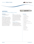
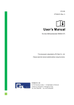
ICS 11.040.70
C 40
National Standard
of the People's Republic of China
GB XXXX-200X
Ophthalmic optics and instruments – Optical
devices for enhancing low vision
(ISO 15253:2000, MOD)
(Draft for approval)
Issue Date: XX – XX– XXXX
Implementation Date: XX – XX– XXXX
Issued by the State Bureau of Quality and Technical Supervision
of the People's Republic of China
-1-
Foreword
The entire technical content of this Standard is mandatory.
This Standard is a modified version of ISO 15253:2000 (Ophthalmic optics and instruments –
optical devices for enhancing low vision) (English edition).
The main modifications to this Standard compared to ISO 15253:2000 are as follows:
− GB/T16886.1 (Biological evaluation of medical devices – Part 1: Guidance on selection of
tests) and ISO 14490-5 (Optics and optical instruments – Test methods for telescopic
systems – Part 5: Test methods for transmittance) have been added as normative references.
− Section 5.2.1, material requirements, has been added;
− Appendix B to ISO 15253:2000 has been deleted.
Appendix A to this Standard is an informative appendix.
This Standard is proposed by the State Food and Drug Administration.
This Standard is under the jurisdiction of the Technical Branch Committee of Chinese Medical
Optics and Instruments Standardisation.
The main organisation that participated in the drafting of this Standard:
State Drug Administration Hangzhou Centre for Medical Equipment Quality Supervision and
Testing
The main drafters of this Standard:
He Tao, Yan Qinglai, Zheng Jian
-2-
Table of Contents
1
Scope
2
Normative references
3
Terms and definitions
4
Classification
5
Requirements
5.1
Optical characteristics
5.2
Materials and construction
6
Environmental condition of use
7
Test methods
8
Marking and instruction for use
Appendix A (Informative) Determination of lateral variation of magnification
-3-
4
4
4
9
10
10
11
12
12
16
18
Ophthalmic optics and instruments –
Optical devices for enhancing low vision
1 Scope
This Standard applies to the optical devices provided by the manufacturers for use by visually
impaired persons as optical low vision aids. It also applies to optical devices with electrical
components (such as illuminators).
This Standard specifies the optical and mechanical requirements and test methods for optical
devices.
This Standard does not apply to electro-optical devices for enhancing low vision.
Note: electro-optical devices for enhancing low vision are specified by other Standards.
2 Normative references
The provisions of the following documents become provisions of this Standard after being
referenced. For dated reference documents, all later amendments (excluding corrigenda) and
versions do not apply to this Standard; however, the parties to the agreement are encouraged to
study whether the latest versions of these documents are applicable. For undated reference
documents, the latest versions apply to this Standard.
GB/T 14214 Spectacle frames – General requirements and test methods
GB/T 16886.1 Biological evaluation of medical devices – Part 1: Guidance on selection of tests
ISO 14889 Ophthalmic optics – Spectacle lenses – Fundamental requirements for uncut finished
lenses
ISO 14990-5 Optics and optical instruments – Test methods for telescopic systems – Part 5: Test
methods for transmittance
ISO 15004 Ophthalmic instruments – Fundamental requirements and test methods
3 Terms and definitions
The definitions and terms listed below apply to this Standard.
3.1 Astronomical telescope
Keplerian telescope
Compound optical system, focal in normal adjustment, consisting of a positive objective element or
group and a positive ocular element or group forming a magnified, inverted image.
3.2 Binocular aid
Optical device, usually consisting of two separate optical systems mounted in alignment, intended
for use with both eyes simultaneously.
-4-
3.3 Biocular aid
Optical device, using which both eyes view through a single optical system.
3.4 Distance cap
The negative lens that is positioned in front of the objective element of a near-vision telescope or
telemicroscope, which enables the device to view target objects from a long distance.
3.5 Equivalent power
The reciprocal of the equivalent focal length measured in the air, represented by metre.
Note: equivalent power is represented by dioptre or inverse metre (m-1).
3.6 Eyepiece ocular
The optical element set in the optical image system which is closest to the eye(s), used for viewing
the image formed by objective element(s).
3.7 Focal length
The linear distance from the prime focal point (or focal point) of the optical system to the reference
point; see Diagram 1.
Note: on the basis of the selection difference of the reference point (such as vertex, principal point),
the focal length is required to be further specified; see Sections 3.7.1 to 3.7.3 for the definition.
3.7.1 Back vertex focal length
In an optical system, the distance measured from the rear surface to the rear focal point, along the
optical axis (symmetrical axis). See Diagram 1.
3.7.2 Front vertex focal length
In an optical system, the distance measured from the front surface to the front focal point, along the
optical axis (symmetrical axis). See Diagram 1.
3.7.3 Equivalent focal length
In an optical system, the distance measured from the focal point to the relevant principal point,
along the optical axis (symmetrical axis). See Diagram 1.
3.8 Focussing telescopic device
A telescopic device, the focus adjustment of which is carried out by the user based on the distance
of the target object.
3.9 Free working distance
The (optical low vision enhancing) distance from the front-most part of a near-vision
telescope/telemicroscope to the target object.
-5-
1- Front vertex focal length
2- Back vertex focal length
3- Front focal length
4- Back focal length
Diagram 1 Schematic diagram of focal length
3.10 Galilean telescope
Compound optical system, focal in normal adjustment, consisting of a positive objective element or
group and a positive ocular element or group forming a magnified, inverted image.
3.11 Hand magnifier
A device with no manual support structure, but positioned and supported by the hands of the user.
3.12 Linear field of view
Under the service conditions specified by the manufacturer, the maximum visible plane range of a
target object viewed through a low vision aid.
3.13 Low vision aid
The devices used for enhancing the visual acuity of persons who are visually impaired.
3.14 Low vision aid telescope
An optical device such as a Keplerian or Galilean telescope, which can form a magnified retina
image of a target object.
3.14.1 Hand telescope
A telescope which is designed to be hand-held.
3.14.2 Spectacle telescope
A telescope which is mounted or attached onto a spectacle frame.
-6-
3.15 Magnification
The ratio between the linear dimension of the fundus image viewed with a magnifying device and
the dimension of the same target object viewed without the magnifying device.
3.15.1 Angular magnification
At the reference observation point (example: the entrance pupil of an eye), the ratio between the
opposite side of the image angle and the opposite side of the target object angle.
3.15.2 Nominal magnification, M
For magnifiers, the nominal magnification shall be determined by the product of the reference
seeing distance (use metre as unit, see 3.20) and the equivalent power F (use dioptre as unit, see
3.5).
Example: when the reference seeing distance is 0.25 m, the nominal magnification shall be
determined by the formula M=0.25F.
3.15.3 Trade magnification, Mtrade = M + 1
For magnifiers, the trade magnification shall be determined by the following formula:
Mtrade = M + 1
Note: the reason for adopting this definition of trade magnification here is due to trade
magnification being mentioned in many textbooks. This term shall not be further adopted in
the future.
3.16 Magnifier
Low vision – aid microscope
The lens system which is designed for generating magnified images.
Note: a magnifier can be a single lens or multiple element system.
3.16.1 Spectacle magnifier
Spectacle microscope
A magnifier which can be attached onto a spectacle frame or a magnifier which can be worn or
supported close to the eyes as a spectacle, including optical devices which contain additional
spectrophotometric for correcting near vision.
3.16.2 Illuminated magnifier
Magnifiers equipped with illuminators.
3.17 Monocular aid
A type of optical device that can only be used in front of one eye.
3.18 Optical dimensions
Zone of optical dimensions
-7-
optical zone of magnifier
The selectable linear dimension which is fitted as a magnifier.
Note: the unit is millimetre.
3.19 Reading cap
The positive lens which is positioned in front of a telescope objective, in order to clearly view target
objects in the near distance through the device.
3.20 Reference seeing distance (least distance of distinct vision)
The generally acknowledged distance from the anterior vertex of the cornea to an observation target
object shall be 250 mm.
Note: the reference seeing distance shall be a primary reference value used for calculating the
magnification of optical instruments for near observation.
3.21 Relation distance magnification
Adjusting the observation distance leads to the dimension changing of a retinal image.
3.22 Resolution
Under a series of given conditions, the resolution distance between two minimal points, represented
by linear value or angle value.
3.23 Stand magnifier
The supporting part of a magnifier which is designed to fix or adjust the distance between an optical
system and its observation target object.
3.23.1 Vertex image distance
For stand magnifiers, when the object is placed at the designated location, the distance between the
magnifier surface which is nearest to the eye and the virtual image plane. See Diagram 2.
3.23.2 Exit image vergence
The reciprocal of the vertex image distance (unit: metre) of a stand magnifier.
Note: unit is dioptre.
-8-
1 – Vertex image distance
2 – Image plane
3 – Object plane
Diagram 2 Schematic diagram of vertex image distance, image plane and object plane
3.24 Telemicroscope
Near-vision telescope
Telescopes which are suitable for viewing near distance target objects.
3.25 Terrestrial telescope
An astronomical telescope positioned on a stand support system.
4 Classification
4.1 Magnifier
a) Hand magnifiers
b) Stand magnifiers
c) Head-worn magnifiers, including spectacle magnifiers or magnifiers which are mounted
onto spectacle frames
4.2 Telescope – distance vision telescope
a) Hand magnifiers
b) Head-worn magnifiers, including spectacle magnifiers or magnifiers which are mounted
-9-
onto spectacle frames.
4.3 Telescope – near vision telescope /telemicroscope
a) Hand magnifiers
b) Head-worn magnifiers, including spectacle magnifiers or magnifiers which are mounted
onto spectacle frames
4.4 Telescope – focusable
a) Hand magnifiers
b) Head-worn magnifiers, including spectacle magnifiers or magnifiers which are mounted
onto spectacle frames
5 Requirements
5.1 Optical characteristics
5.1.1 Resolution
5.1.1.1 General provisions
The contrast ratio of a visual target used for measuring the resolution of an optical device shall not
be less than 80%.
5.1.1.2 Magnifiers and telemicroscopes/near-vision telescopes
When the test is conducted in accordance with Section 7.4, within the range of 70% linear visual
field, the vision aid shall be able to resolve a target which is not more than 0.233 mm per line pair
(0.116 mm per line); the light source of the white light illuminating on the target shall adopt the CIE
standard illuminant D65, and the range of the light intensity shall be between 750lx and 1000lx.
5.1.1.3 Telescopes
When the test is conducted in accordance with Section 7.4, with the range of 70% linear visual field
or within the angle range of 10o visual field, the vision aid shall be able to resolve a target which
has an opposite angle of 1' (or smaller) and is composed by a line pair forming an opposite angle of
2' ( or smaller). If this requirement exceeds the diffraction limit of the vision aid, then a single light
of 555 nm shall be selected to illuminate. Within the range specified above, the resolution of a
vision aid shall be smaller than 50% of the diffraction limit; within the stipulated working range, the
telescope shall reach the abovementioned requirements.
5.1.2 Equivalent power – magnifiers
The permissible error between the equivalent power along the optical axis of a magnifier and the
nominal value deviation shall be 5%. The mutual difference of the optical power between two
principal meridians shall not exceed 2.5%.
The two principal meridians are the main parameters for designing magnifiers; the deviation
between the equivalent power and the maximum optical power of the two principal meridians must
not exceed 2.5%.
- 10 -
5.1.3 Angular magnification - magnifiers
The permissible error between the equivalent magnification along the optical axis of a magnifier
and the nominal value deviation specified by the manufacturer shall be 5%.
5.1.4 Lateral magnification variation – magnifiers and telescopes
When the method specified in Section 7.5 is selected to test the linear visual field of an instrument,
the magnification variation beyond 70% of the linear visual field shall meet the specifications
prescribed in Table 1 or Table 2.
The manufacturer shall specify the test method.
Table 1 Magnifiers / near-vision telescopes
Equivalent power (Unit: dioptre)
Lateral magnification variation (%)
≤ 12
5
12 ~ 20
10
≥ 20
15
Table 2 Distance vision telescopes
Magnification
Lateral magnification variation (%)
≤ 3x
2.5
3x ~ 5x
5
≥ 5x
7.5
5.1.5 Transmittance
If the manufacturer specifies any transmittance requirements, then the measurement shall meet the
criteria specified in ISO 14490-5 and appropriate transmission curves shall be provided.
5.2 Material and construction
5.2.1 Material
When a device is used as the expected purpose of the manufacturer, then the material selected for
the components which come into direct contact with the patient’s skin shall not be toxic, or enable
serious hypersensitive reaction, and shall be subject to a medical device biological evaluation in
accordance with the criteria specified in GB/T 16886.1.
5.2.2 Flammability
According to the provisions set out in ISO 15004, tests shall be conducted on the vision aids;
continuous combustion is not permitted after the test rod has been removed.
5.2.3 Immersion resistance
Any instrument that is indicated as being immersion resistant shall meet the following
requirements:
Submerge the whole instrument in water at a temperature of 40oC ~ 50oC for 5.0 min± 0.5 min, and
- 11 -
then dry it in air at a temperature of 20oC ± 5oC. Conduct the test; the test result shall meet the
requirements of this Standard.
5.2.4 Sweat resistance
In the case of a vision aid that contains a spectacle frame which conforms to the standard limit set
out in GB/T 14214, the requirements of its sweat resistance shall meet the relevant requirements of
this Standard.
5.2.5 Mechanical strength of head-worn type (including spectacle type and spectacle mounted
aids)
In the case of a vision aid that contains a spectacle frame and lens which conforms to the standard
limit of GB/T 14214 and ISO 14889, the mechanical strength thereof shall meet the relevant
requirements of this Standard.
5.2.6 Drop resistance characteristics
If a manufacturer claims that a vision aid is drop-resistant, then the said manufacturer shall specify
the conditions under which this claim is made, and provide a test method.
6 Environmental condition of use
Under the environmental conditions of use prescribed in Table 3, shall meet all the requirements of
this Standard. These requirements have precedence over the requirements specified in Section 5.1 of
ISO 15004.
Table 3 Environmental conditions of use
Item
Environmental condition of use
a
Temperature
-25oC ~ +35oC
Relative humidity
30% ~ 80%
Atmospheric pressure
800hPa ~ 1060hPa
Vibration (unpacked)a
10 g/6 ms
Applies only to handheld instruments
7 Test method
7.1 General provisions
All test methods are type tests. Other equivalent test methods are permitted, but the manufacturer or
persons conducting the test are responsible for ensuring that the selected test methods are
equivalent.
7.2 Equivalent power – magnifiers
The method selected to test equivalent power shall reach the condition of 95% confidence level and
a relative uncertainty of less than 0.5%.
7.3 Angular magnification – telescopes
The method selected to test angular magnification shall reach the condition of 95% confidence level
and a relative uncertainty of less than 0.5%.
- 12 -
7.4 Resolution test
7.4.1 Test principles
The following equipment is used for the resolution test of low vision aids. The resolution plate
consists of four sets of Ronchi fringes with different directions of 90o, 180o, 45o and 135o (see
Diagram 3). When the fringes on different directions can be clearly observed, then the resolution is
indicated to be achieved. During the test process, the linear visual field, which is able to clearly
view the resolution, shall be determined. The visual acuity of the observer shall be at least 1.0
(logarithmic visual acuity is 5.0).
Diagram 3: Example of resolution plate
7.4.2 Test equipment
7.4.2.1 General provisions
Set up the test equipment on an optical bench. Mount a resolution plate onto a white screen which
can be adjusted to 90o angle from the optical bench. The adjustable range shall be at least equal to
the horizontal range of the visual field of the low vision aid undergoing the test.
The standard D65 light source shall be selected as the illumination light source for the screen and
the fringes, and the light intensity on the plane of the resolution plate shall be 750lx to 1000lx. The
line-width of the resolution plate is b=0.116 mm and the contrast ratio shall be at least 80% (see
Diagram 3).
Note: the most suitable resolution plate is a metal coated glass plate.
7.4.2.2 Magnifiers and telemicroscopes/near vision telescopes
The vision aid is fitted in front of a resolution plate. The distance between the vision aid and the
resolution plate shall be adjustable.
Place an observation telescope with between 3 and 8 times angular magnification in front of the
vision aid, and focus on the image plane of the resolution plate.
During the measuring process, re-focussing is not permitted.
- 13 -
Diagram 4 shows the example of the test equipment. Before the measurement, pre-adjust the test
equipment to enable the x and y directions of the resolution plate, the low vision aid and the
positioning of the observation telescope to be mutually matched.
According to the distance between the eyes of the user and the low vision aid prescribed in the user
manual, adjust the distance between the near low vision aid and the observation telescope.
According to the provisions specified in the manufacturer’s user manual, adjust the distance
between the near vision aid and the resolution plate.
1 – Observation telescope
2 – Near vision aid
3–Light source of the screen
4–Screen equipped with a resolution plate
Diagram 4 Example of test equipment for near vision aid
7.4.2.3 Telescopic vision aid
Place a collimating lens in front of a resolution plate, allowing the resolution plate to be positioned
at the focal plane of this lens. At this point the resolution plate can image through the lens at an
infinite distance.
To ensure the angle of the visual field does not change, when the line width of the resolution plate is
b=0.116 mm, the equivalent focal length of the collimating lens shall be equal to 400 mm.
The equivalent focal length of a collimating lens can be determined by the following formula:
f' = b/tan α....................................(1)
tan α = b/f'....................................(2)
In the formula:
Line width b=0.116 mm
Angle of visual field α=1'=0.0116o (unit of α: degree)
Hence, f'=400 mm.
The range of the visual field of the telescope system shall not be restricted by the collimating lens,
neither shall the resolution be effected by this lens, but shall only be determined by the system
undergoing the test. For this reason, the diameter of the collimating lens shall be at least 1.2 times
- 14 -
the entrance pupil diameter of the telescopic vision aid.
Diagram 5 shows the example of the test equipment. Before the measurement, adjust the test
equipment to enable the x and y directions of the resolution plate, the vision aid and the positioning
of the observation telescope to be mutually matched.
Reduce the distance between the telescopic vision aid undergoing the test and the collimating lens
as much as possible so as to ensure that the visual field is not restricted by the collimating lens.
With regard to a telescopic vision aid with adjustable focus, adjust the distance between the
collimating lens and the resolution plate, so as to enable the distance to be equal to the equivalent
focal length of the collimating lens.
With regard to a telescopic vision aid with non-adjustable focus, adjust the distance between the
collimating lens and the resolution plate so as to enable the clear imaging of the resolution plate on
the vision aid.
1-Telescopic vision aid
2-Collimating lens
3-Light source of the screen
4 Screen equipped with a resolution plate
Diagram 5 Example of test equipment for telescopic vision aid
7.4.3 Test procedure
7.4.3.1 Magnifiers and telemicroscopes/near vision telescopes
After the test equipment is adjusted precisely, measure the achievable range of the visual field of the
vision aid. Move the resolution plate to the edge of the stand which is used for fixing the low vision
aid, and measure the visible range of the resolution plate. Move the resolution plate horizontally and
vertically; during this process, the observation telescope may need to be moved to a new location.
Measure the range of the visual field in horizontal and vertical directions respectively. Two values
can be obtained:
Ahor = horizontal range of the linear visual field, unit: mm
- 15 -
Avert = Vertical range of the linear visual field, unit: mm
Repeat the process outlined above. Move the resolution plate towards the edge of the visual field,
until the direction of the Ronchi fringe cannot be clearly observed. The rod readings shall be
regarded as the resolution range of the visual field in horizontal and vertical directions. Once again
read out the rod reading, and then the range of the visual field in horizontal and vertical directions
can be obtained. During this process, the focus of the observation telescope must not be readjusted.
Two values can be obtained:
Ahor = resolution horizontal range of the linear visual filed, unit: mm
Avert = resolution vertical range of the linear visual filed, unit: mm
If the vertical movement meets any difficulty, then the vision aid can be rotated by 90 degrees in
order to measure the range in the vertical direction.
7.4.3.2 Telescopic vision aid
After the test equipment is adjusted precisely, measure the achievable range of the visual field of the
low vision aid. Move the resolution plate to the edge of the stand which is used for fixing the low
vision aid, and measure the visible range of the resolution plate. During the test, move the
resolution plate to measure the ranges of the visual field horizontally and vertically; two values can
be obtained respectively:
Ahor = horizontal range of the linear visual filed, unit: mm
Avert = vertical range of the linear visual filed, unit: mm
Repeat the process outlined above. Move the resolution plate towards the edge of the visual field,
until the direction of the Ronchi fringe cannot be clearly observed. Repeat again; the rod readings
shall be regarded as the resolution range of the visual field.
Ahor* = resolution horizontal range of the linear visual filed, unit: mm
Avert*= resolution vertical range of the linear visual filed, unit: mm
If the vertical movement meets any difficulty, then the vision aid can be rotated by 90 degrees in
order to measure the range in the vertical direction.
7.4.4 Test evaluation
The percentage of a resolution linear visual field can be determined by formula (3):
(A* x 100)
/A..................................................... (3)
7.5 Determination of lateral variation of magnification
The measurement of the lateral variation of magnification shall be conducted under the conditions
specified in the user manual provided by the manufacturer. Under the condition of 95% confidence
level, the instrument used for testing the transverse distortion of magnification shall have
uncertainty of 0.5%.
Note: Appendix A gives the example of a test method.
8 Marking and instruction for use
8.1 Marking
Each vision aid shall be clearly marked with the following information:
a) the names of the manufacturer and product;
b) the nominal value of magnifier equivalent power provided by the manufacturer;
Each vision aid (with the exception of customer oriented models) shall be marked at least with
the following information:
c) the nominal value of the angular magnification of the telescope specified by the
manufacturer;
- 16 -
d) the nominal value of the nominal magnification or the equivalent power of the
telemicroscope/ near-vision telescope specified by the manufacturer.
8.2 Information provided by manufacturer
In addition to the information stipulated in 8.1, the manufacturer shall also provide the following
information for each vision aid:
a) the nominal value of the exit image vergences of stand magnifiers provided by the
manufacturer;
b) the free working distances of telemicroscopes;
c) an instruction on preventing fire hazards caused by the focussing of a magnifier placed
under direct sunlight;
d) instructions on maintenance and cleaning of vision aids;
e) characteristics stipulated in Section 5.2.
When requested, the manufacturer shall publish the following information: weight, lens materials,
optical dimensions of the magnifiers (unit: mm)
- 17 -
Appendix A: Determination of lateral variation of magnification
(Informative Appendix)
A.1 Theory
Use a set of Barrel Distortion Charts to evaluate the lateral variation of the magnification. Under
designated conditions, view suitable dimensioned grids through a magnifier or a telescope, using
the grids which can mostly compensate the distortion of the magnifier to evaluate the pincushion
distortion degree.
A.2 Devices
A.2.1 Hand and stand magnifiers
A.2.1.1 Distortion evaluation charts, generated by method of computer programs, represent the
pincushion distortion of 0%, 5%, 10%, 15% and 20% for the hand magnifier and the stand
magnifier respectively.
A.2.1.2 To enable the position of the distortion evaluation of the magnifier to be standardised, the
frontal support shall be designed so that the adjustment mode is carried out by cross support posts.
A.2.2 Distance vision and focussing telescope
A.2.2.1 Distortion evaluation charts, generated by method of computer programs, represent the
pincushion distortion of 0%, 2.5%, 5%, 7.5% and 10% for distance telescopes respectively. The
sizes of these charts shall be four times the corresponding magnifier charts. Since the working
distance is shorter, these charts are more effective for certain near vision telescopes.
A.3 Procedures
A.3.1 Observation position of the magnifiers
With regard to magnifiers with an object distance that is determined by a stationary frame or a
support, lay the charts flat on a table and place the magnifier in such a way so as to enable the
centre point of the applicable lattices to be aligned to the optical axis of the magnifier. Hand
magnifiers shall be fitted onto a stationary device with adjustable height, enabling the distance
between the detection chart and the magnifier to meet the specifications set out by the manufacturer
in the user manual. Move the stationary device to enable the centre point of the applicable lattices to
be aligned to the optical axis of the magnifier.
Use the frontal support to fix the distortion evaluation device. The distance between the magnifier
and the eyes of the evaluator shall meet the specifications set out by the manufacturer in the user
manual. The eyes of the evaluator shall be on the optical axis of the magnifier.
- 18 -
Note: there are 6 rows in total in this diagram, with decreasing dimensions (see Diagram A.1.b, has
drawn the left side column of this diagram). The lattices from left to right of each row of this
diagram represent Barrel Distortion of 0%, 5%, 10%, 15% and 20% respectively (see Diagram
A.1.c, has drawn the first row of this diagram).
a) General layout charts; the lattices have been simplified into empty square blocks.
Diagram A.1 Example of serial charts for distortion evaluation
- 19 -
b) Left side column of the evaluation chart, represents the lattice sequence of the dimension change
Diagram A.1 Example of serial charts of distortion evaluation (continuation diagram)
- 20 -
c) Fourth row of the evaluation chart; represents the distortion degree of the lattice sequence
Diagram A.1 Example of serial charts of distortion evaluation (continuation diagram)
A.3.2 Observation position of near-vision telescopes
The observation distance of a near-vision telescope is very short. Lay the chart flat on a table and
place the telescope onto a stationary device, enabling the centre point of the applicable lattices to be
aligned to the optical axis of the telescope. Adjust the stationary device until the focussed image of
the chart is visible in the visual field.
A.3.3 Observation position of focussing telescopes and distance vision telescopes
With regard to distance vision telescopes, fix a large chart onto a wall. Fix the device so as to enable
its optical axis to be horizontal and perpendicular to the chart. Adjust the telescope to near point and
achieve the focussed image of the chart in the visual field.
With regard to focussing telescopes, fix a large chart onto a wall six metres away from the
instrument. Fix the instrument to enable its optical axis to be horizontal and perpendicular to the
chart; when a larger chart is used, the focussed image of the chart in the visual field shall be
achievable.
A.4 Evaluation
A.4.1 Magnifiers
Place the hand instrument (by way of fixing onto another device) or stand the instrument at the left
side of the lattices, move the instrument along the left side until just completely filling one row in
the visual field of the instrument.
Next, move the instrument along the right side of this row, stop at the centre of each lattice, and
decide whether or not the borders of the lattice are straight (see Note 2).
Note 1: if the magnifier or telescope is placed onto another device, in order to more conveniently
achieve the necessary manoeuvre, the chart under the instrument can be selectively moved.
Note 2: if there is any pincushion distortion at the borders of the lattices, this indicates that the
pincushion distortion of the magnifier is not completely compensated. If there is any barrel
distortion at the borders of the lattices, this indicates that the pincushion distortion of the magnifier
is over-compensated.
By way of continuously checking every lattice in the row, determine which chart is showing:
a) the borders of all lattices are straight; or
b) if there is no linear image, choose the lattice with the least pincushion distortion.
Report the distortion percentage determined from a) or b).
- 21 -
A.4.2 Near-vision telescope
Generally applies to instruments with a working distance that does not exceed 0.5 m.
Place the instrument to the left of the lattices, and then move the instrument along the left-hand side
until just completely filling one row in the visual field of the instrument.
Move the instrument along right side of this row, stop at the centre of each lattice, and decide
whether or not the borders of the lattice are straight (see Note 2).
Note 1: if the telescope is placed onto another device, in order to more conveniently achieve
the necessary manoeuvre, the chart under the instrument can be selectively moved.
Note 2: if there is any pincushion distortion at the borders of the lattices, this indicates that
the pincushion distortion of the magnifier is not completely compensated. If there is any
barrel distortion at the borders of the lattices, this indicates that the pincushion distortion of
the magnifier is over-compensated.
By way of continuously checking every lattice in the row, determine which chart is showing:
a) that the borders of all lattices are straight; or
b) if there is no any linear image, shall choose the lattice with the least pincushion distortion.
Report the distortion percentage determined from a) or b).
A.4.3 Focus adjustable telescopes for distance vision
With regard to stand telescopes, enable the optical axis thereof to be horizontal and perpendicular to
the chart which is fixed onto a wall. Adjust the telescope to the near point and achieve the focussed
image of the chart in the visual field. For telescopes with adjustable focus, it is necessary to use
larger charts within a distance of 6 m. Choose a lattice which can fill the visual field in the
telescope.
By way of continuously checking every lattice in the row, determine which chart is showing:
a) that the borders of all lattices are straight; or
b) if there is no any linear image, choose the lattice with the least pincushion distortion.
Report the distortion percentage determined from a) or b).
- 22 -