1
Feasibility study Flying Carpet Connection between P+R facility Glimmen and Groningen Airport Eelde by Autonomous Vehicles 119 Name of the Project Flying Carpet Authors J.P.L.H.A. Appel J. Bruinsma R. ten Have N.H. van Steenis J. Wilkens Clients Province Drenthe Groningen Airport Eelde Institute Hanzehogeschool Institute of Engineering (Assen) Center of Applied Research & Innovation on area development Noorderruimte 119 Document date 5 March 2014 Status Final Feasibility Study Flying Carpet Contents page Flying Carpet ...........................................................................................................................................1 Summary .................................................................................................................................................6 Abbreviations and definitions .............................................................................................................12 1 Introduction ...................................................................................................................................13 1.1 1.2 1.3 1.4 1.5 1.6 1.7 1.8 2 “State of the art” Autonomous Vehicle applications ................................................................19 2.1 2.2 2.3 2.4 3 Public Space versus Private Space ...........................................................................................27 Legislation for public space ........................................................................................................28 Legislation for private space .......................................................................................................33 Rail-borne transport systems......................................................................................................39 Stakeholders – Needs and demands ..........................................................................................41 4.1 4.2 4.3 4.4 4.5 5 Low autonomy AGVs ..................................................................................................................20 Medium autonomy AGVs ............................................................................................................23 High autonomy AGVs .................................................................................................................24 Conclusion ..................................................................................................................................25 Safety & regulations .....................................................................................................................26 3.1 3.2 3.3 3.4 4 “Green Sustainable Airport” ........................................................................................................13 Accessibility issues at small airports ..........................................................................................14 Demands for improved accessibility at GAE ..............................................................................14 The location Groningen Airport Eelde ........................................................................................15 The “Flying Carpet” .....................................................................................................................16 Project goal .................................................................................................................................17 Demarcation ...............................................................................................................................17 Structure of the document ..........................................................................................................18 User group ..................................................................................................................................41 Surrounding traffic ......................................................................................................................41 Residents ....................................................................................................................................41 Government ................................................................................................................................42 Exploitation .................................................................................................................................42 Concept .........................................................................................................................................43 5.1 Online booking ............................................................................................................................43 5.2 Arrival P+R facility by car ...........................................................................................................44 5.3 Navigation of car to parking spot ................................................................................................46 5.4 Travellers and luggage into AGV................................................................................................47 5.5 Interaction in and outside vehicle ...............................................................................................48 5.6 AGV brings travellers to departures hall at airport .....................................................................49 5.7 AV brings travellers from airport to parking spot ........................................................................49 5.8 Exiting the car park .....................................................................................................................49 5.9 Flowchart “Traveller to GAE” ......................................................................................................50 5.10 Flowchart “Traveller to car park”.................................................................................................50 6 Design of System Safety..............................................................................................................51 6.1 Safety devices ............................................................................................................................51 6.2 AGV form factor ..........................................................................................................................52 6.3 Other safety measures ...............................................................................................................53 Version/status: Final Page 3 of 119 Feasibility Study Flying Carpet 7 Design of Automated Guided Vehicle System ..........................................................................54 7.1 7.2 7.3 7.4 7.5 7.6 7.7 7.8 8 Navigation ...................................................................................................................................54 Interaction chart ..........................................................................................................................57 Infrastructural measures – Cameras to supervise traffic ............................................................58 Weather conditions .....................................................................................................................58 TOMS - Central Control System .................................................................................................59 Communication network .............................................................................................................60 Costs ...........................................................................................................................................61 Conclusion ..................................................................................................................................61 Design of Smart Parking System ................................................................................................62 8.1 8.2 8.3 8.4 8.5 8.6 8.7 9 P+R facility map..........................................................................................................................62 Smart Parking System overview.................................................................................................64 Parktrac - Access control............................................................................................................65 Vivaldi – Dynamic Parking Management ....................................................................................67 Flowchart ....................................................................................................................................68 Costs ...........................................................................................................................................69 Conclusion ..................................................................................................................................69 Design of integration of AGV and Smart Parking systems ......................................................70 9.1 Data sharing ...............................................................................................................................70 9.2 System blocking prevention ........................................................................................................71 10 Design of the infrastructure ........................................................................................................72 10.1 Route through the business park................................................................................................72 10.2 Traffic Control System ................................................................................................................73 10.3 Bottlenecks in the route ..............................................................................................................74 10.4 Costs of the infrastructure ..........................................................................................................74 10.5 Required preparations ................................................................................................................75 10.6 Conclusion ..................................................................................................................................76 11 Energy efficiency ..........................................................................................................................77 11.1 Bus ..............................................................................................................................................77 11.2 Automated Guided Vehicle System ............................................................................................78 11.3 Conclusion ..................................................................................................................................78 12 Feasibility discussion ..................................................................................................................79 12.1 Juridical.......................................................................................................................................79 12.2 Technical ....................................................................................................................................80 12.3 Economic ....................................................................................................................................82 12.4 Conclusion Feasibility .................................................................................................................84 13 Conclusion and recommendation ..............................................................................................85 13.1 Key conclusions ..........................................................................................................................85 13.2 Further conclusions ....................................................................................................................87 13.3 Recommendation ........................................................................ Error! Bookmark not defined. 14 References ....................................................................................................................................89 Appendix A Existing AGV application ................................................................................................90 Appendix B Scenario Analysis ...........................................................................................................91 Version/status: Final Page 4 of 119 Feasibility Study Flying Carpet Appendix C Analysis of Functions ...................................................................................................103 Appendix D Opportunities for expansion ........................................................................................110 Appendix E Details concerning the design of the infrastructure ..................................................113 E.1 Details of the route through the business park ..........................................................................113 E.2 Alternative route along the canal ...............................................................................................118 E.3 A detailed estimation of the road construction costs .................................................................119 Version/status: Final Page 5 of 119 Feasibility Study Flying Carpet Management samenvatting Green Sustainable Airport (GSA) is een Interreg IVB project dat onderdeel is van de North Sea Region program en is een initiatief van Groningen Airport Eelde (GAE). Een van de doelen van het GSA project is: Het ontwikkelen van duurzame en innovatieve oplossingen die bijdragen aan een meer duurzame exploitative en verbeterde toegankelijkheid van alle partner vliegvelden Momenteel wordt er wereldwijd veel onderzoek gedaan naar autonome voertuigen. Dit zijn voertuigen die zonder bestuurder rijden. Omdat deze ontwikkelingen snel gaan en een grote impact op onze maatschappij zullen hebben moeten we ons daar op voorbereiden. Dergelijke voertuigen zijn ook zeer interessant om de bereikbaarheid van regionale vliegvelden te verbeteren. In dit onderzoek, genaamd vliegend tapijt, is onderzocht of het mogelijk is om een verbinding te realiseren tussen GAE en een nieuw aan te leggen transferium bij afslag de Punt van de A28 door middel van autonome voertuigen. Het concept dat is onderzocht gaat verder dan de verbinding door autonome voertuigen alleen. Het concept start bij het boeken van de vlucht. Aangegeven kan worden of de reiziger(s) al dan niet met de auto of bus komt. Als men met de auto komt kan de reiziger(s) ervoor kiezen om het kenteken bij het boeken doorgegeven. Aangekomen bij het parkeerterrein herkent het Smart Parking Systeem de auto van de reiziger(s) en verwijst de bestuurder naar een leeg parkeervak. Hierdoor verloopt het parkeren snel en efficiënt. Vervolgens komt een autonoom voertuig de reiziger(s) halen bij de zojuist geparkeerde auto. Daarna rijdt het voertuig stapvoets over het parkeerterrein naar een speciale rijbaan die leidt naar GAE. Op deze speciale rijbaan zal de snelheid naar ongeveer 40 km/h worden opgevoerd. In het voertuig is een beeldscherm aanwezig waarmee de reiziger informatie kan verkrijgen over bijvoorbeeld de status van de vlucht, nieuws, weersverwachting en promotie van diensten op de bestemming. Op deze manier bereikt de reiziger binnen enkele minuten het vliegveld. Bereikt de reiziger het transferium met een bus vanuit Groningen, Assen of Emmen, dan loopt de reiziger naar het nabij gelegen halte voor autonome voertuigen en belt een speciaal nummer of drukt op een knop om aan te geven dat de reiziger behoefte heeft aan een transfer. Vervolgens komt een autonoom voertuig voorrijden en vervolgt het proces op dezelfde manier als hierboven beschreven voor de auto. Als de reiziger aankomt op GAE zal een autonoom voertuig de reiziger oppikken bij de halte voor autonome voertuigen in de aankomsthal en vervolgens afzetten bij hun auto. Het inzetten van autonome voertuigen voor personenvervoer tussen een parkeerplaats en een vliegveld waarbij de reizger(s) bij hun geparkeerde auto worden opgehaald in combinatie met Smart Parking is tot nu toe nergens ter wereld toegepast. Deze aspecten maken dit project uniek. Onderzocht is of de hiervoor genoemde verbinding technisch, juridisch en economisch haalbaar is. In het kader van de technische haalbaarheid is onderzocht of het mogelijk is om een dergelijke verbinding op een veilige manier te realiseren door het combineren van reeds ontwikkelde technologie. Tevens is onderzocht of het mogelijk is om deze technologie in te passen in de ruimte en met welke technologie het concept gerealiseerd kan worden. In het kader van de juridische haalbaarheid is onderzocht welke mogelijkheden en belemmeringen er zijn vanuit wet- en regelgeving. En tot slot is in het kader van de economische haalbaarheid nagegaan wat de kosten zijn van een dergelijk systeem en welke baten (financiële en niet financiële) daar tegen over staan. Version/status: Final Page 6 of 119 Feasibility Study Flying Carpet Hoofdconclusies en aanbevelingen Juridische haalbaarheid Het aanleggen van het hiervoor beschreven concept lijkt binnen de kaders van de wet en regelgeving mogelijk. Hier staat lijkt omdat het een nieuwe situatie is waarbij betrokken partijen een definitief standpunt moeten in nemen. De belangrijkste maatregelen om de veiligheid te waarborgen zijn: Het parkeerterrein waar het autonome voertuig gaat rijden als privaatgebied aanmerken (dit moet voor alle gebruikers duidelijk zijn) Het voertuig met een lage snelheid (5 km/h) over het parkeerterrein laten rijden De wielen bedekken Voertuigen voorzien van sensoren die omgeving herkennen Kruispunten voorzien van camera‟s De speciale rijbaan tussen transferium en vliegveld ook aanmerken als privaatgebied Op deze speciale rijbaan mogen alleen autonome voertuigen rijden Het kruisen van wegen gaat op dezelfde manier als bij treinverkeer, dus met verkeersbomen Technisch haalbaarheid Het aanleggen van het genoemde concept is mogelijk door het combineren van reeds ontwikkelde technologie en is inpasbaar in de ruimte. Economische haalbaarheid Vanuit oogpunt van kosten is het aanleggen van een verbinding tussen transferium Glimmen en GAE met autonome voertuigen niet aan te bevelen. De investeringskosten per vervoerde persoon zullen hoog zijn. Belangrijkste oorzaak hiervan is dat de vervoersbehoefte over de dag slechts enkele (meestal maar één) pieken kent. Zo‟n piek treedt op bij aankomst en vertrek van een vliegtuig. De capaciteit van het systeem moet echter wel berekend zijn op dergelijk pieken, ter voorkoming van lange wachttijden. Gedurende het grootste deel van de dag zal echter deze capaciteit niet of nauwelijks benut worden. Hierdoor wordt de investering niet efficiënt benut. Een conventionele busverbinding zal daardoor veel goedkoper zijn (maar ook een lagere kwaliteit bieden). Vanuit oogpunt van verwerven van kennis (technisch en juridisch), marketing (promotie GAE en Noord Nederland), werkgelegenheid en economische ontwikkeling kan een dergelijke verbinding wel interessant zijn. De voordelen van deze aspecten zijn echter moeilijk in geld uit te drukken. Hierdoor is het moeilijk om vast te stellen of de baten van deze verbinding op wegen tegen de kosten. Op basis hiervan wordt aangeraden: Om het in dit document beschreven concept in een vereenvoudigde vorm aan te leggen. Het concept wordt in dat geval niet meer gezien als het realiseren van een vervoersverbinding, maar als onderzoeksproject (living lab). Hierdoor zullen de investeringskosten substantieel dalen. Op deze manier kan invulling worden gegeven aan de niet materiële behoeften zoals: verwerven van kennis, marketing, werkgelegenheid en economische ontwikkeling. Om een analyse uit te voeren naar een interessante locatie waar een verbinding met autonome voertuigen wel commercieel uitgevoerd kan worden. Belangrijk hierbij is dat de vervoersvraag minder hoge pieken kent en meer verspreid is over de dag. Mogelijke verbindingen zijn: o Assen met een buitenwijk (bijvoorbeeld Marsdijk) o Assen-Stadskanaal via Gieten over de voormalige spoorlijn Version/status: Final Page 7 of 119 Feasibility Study Flying Carpet Investeringskosten Om het complete systeem te implementeren met voldoende capaciteit om wachttijden te voorkomen is een investering nodig van tussen de € 8,9 en € 11,7 miljoen. Dit bedrag is inclusief 12 voertuigen, infrastructuur en Smart Parking. Zoals hierboven aangegeven wordt aangeraden het concept te vereenvoudigen tot een onderzoeksproject. In dat geval dalen de kosten doordat: Slechts een voertuig nodig is Smart Parking is ook wenselijk bij aanleg van transferium zonder verbinding met autonome voertuigen. Dit bedrag hoeft dan niet te komen op conto van het onderzoeksproject. De certificeringskosten lager zijn; het project is immers niet meer bedoeld om mensen te vervoeren. De kosten voor engineering en projectmanagement zullen lager zijn omdat in het geval van een onderzoeksproject geen vlekkeloos functioneren vereist is. In het geval het project als een onderzoeksproject wordt gezien zullen hierdoor de kosten dalen tot € 3,4 tot € 5,1 miljoen. Bedrijven die in het kader van dit onderzoek betrokken zijn geweest, hebben aangegeven belang te hebben bij het op te zetten praktijkonderzoek en de intentie te hebben, te willen bijdragen in de investeringskosten, bij voorkeur in kind (materialen, programmatuur en onderzoekscapaciteit). Energie efficiëntie Door het realiseren van een verbinding tussen het transferium en GAE met autonome voertuigen in plaats van een bus (half uursdienst) wordt het energieverbruik met ongeveer een factor 4 verlaagd. Dit draagt bij aan het doel van Green Sustainable Airports om duurzame oplossingen te implementeren. Version/status: Final Page 8 of 119 Feasibility Study Flying Carpet Management summary Green Sustainable Airport (GSA), an Interreg IVB project that is part of the North Sea Region Program, is an initiative of Groningen Airport Eelde (GAE). One of the goals of the GSA project is: The development and testing of sustainable and innovative applications that contribute to a more sustainable exploitation and increased accessibility of all partner airports. Currently a lot of research in the field of autonomous vehicles is carried out globally. Autonomous vehicles drive without a human driver; they are computer driven. We have to prepare ourselves for this technology, because these developments advance rapidly and will have a significant impact on society. Such vehicles are also interesting to improve accessibility to regional airports. In this research, named the “Flying Carpet”, the feasibility of using autonomous vehicles for passenger transfer between a future P+R facility at Glimmen and Groningen Airport Eelde is examined. The proposed concept goes beyond this autonomous vehicle connection. The concept starts with an online booking of the flight, where the traveller(s) will indicate whether they will arrive by bus or by car. If the traveller(s) arrive by car, the traveller(s) may choose to provide the License Plate number of their car. Once arrived at the parking facility, the Smart Parking System will recognize their car and assign them an empty parking spot. This allows a comfortable and efficient transfer. An autonomous vehicle will then be sent to their car, after which they may enter the vehicle together with their luggage. The vehicle then drives at a footpace from the parking facility to the dedicated autonomous vehicle lane. This lane ends at GAE, where the vehicles will drive approximately 40 km/h to allow a fast transfer of just a few minutes. Inside, the traveller may interact with a display that informs about flight status, news and weather updates and promotions of available services at the flight‟s destination. If the traveller(s) arrive by bus at the parking facility from Groningen, Assen or Emmen, they will then walk to the nearby autonomous vehicle station. There, they can request a vehicle to drive them to the airport in the same process as described for traveller(s) arriving by car. When the traveller returns to GAE after the travel, an available vehicle at the autonomous vehicle station inside GAE will bring the traveller to his/her parked car at the parking facility. Using autonomous vehicles for passenger transfer between a parking facility and an airport, as well as the combination of an autonomous vehicles and a Smart Parking system have never been applied before, which are two areas that makes this project unique. Feasibility is researched on a technical, juridical and economic level. Technical feasibility discusses current “state of the art” technologies concerning autonomous vehicles applied worldwide, as well as whether a chosen manufacturer is able to deliver the technology required for the proposed concepts. Technology to guarantee safety is the most significant issue here, which is required due to juridical constraints. Juridical feasibility discusses the possibilities and constraints concerning laws and regulations. Economic feasibility discusses the costs and benefits of the proposed concept versus a conventional transfer connection. Version/status: Final Page 9 of 119 Feasibility Study Flying Carpet Based on the research done in this project, the following conclusions can be made: Juridical feasibility Implementing the proposed connection seems juridically feasible. The feasibility cannot be guaranteed, because it is a new situation whereby involved parties need to present a definitive answer, which at this stage is not possible. The most important measures to guarantee safety include: The parking facility where the AGV will drive needs to be private area, which should be signalled by traffic signs to vehicles and pedestrians making use of the facility The AGV needs to drive at low speed (5 km/h) Cover the wheels Safety sensors implemented on the vehicle that detect the environment A camera system at every crossing The special AGV lane between the parking facility and GAE needs to be private area Only AGVs are allowed to make use of this lane (prohibited for pedestrians too) Crossings with the AGV lane are managed by certified Traffic Control Systems Technical feasibility Realizing the proposed concept has been indicated by the involved companies to be technically feasible, given that additional (existing) technologies will still need to be implemented. Economic feasibility From a financial point of view, implementing an AGV connection is not recommendable. The investment costs per transported passenger will be high, mainly because the transfer demand throughout a given day only has a few, if not just one, peak during arrival or departure of a flight. The capacity of the system does, however, need to be calculated to be prepared for peak moments, making investment for such a system not viable. A conventional bus transfer will be more cost efficient, but will also offer lower quality. Therefore, choosing the AGV connection option should not be based on a financial point of view, but instead on gaining non-tangible assets in favour of GSA and GAE. These include the development of technical and juridical knowledge, marketing (promotion of GAE and the Northern region), employment and economic development. These aspects are, however, difficult to express in monetary value, which makes it challenging to determine whether the benefits weigh up to the investment costs. Version/status: Final Page 10 of 119 Feasibility Study Flying Carpet Based on this, the following is recommended: To realize the concept in a simplified version. In this case, the connection will only serve as a research project (living lab) and will not be meant as a transport connection to be used by the public. Setting up a research project will gain non-tangible assets, including the development of knowledge, marketing, employment and economic development. To analyse alternative locations where the proposed concept is commercially attractive. Important is that the transport demand on this location has lower peaks and has a more spread demand over the day. These locations may be: o Assen with a suburb (such as Marsdijk) o Assen-Stadskanaal through Gieten over the former railroad Investment costs To realize the complete system proposed in this feasibility study with sufficient capacity to keep waiting times minimal, an investment of between €8.9 and €11.7 million is required (see section 12.4). This amount includes the delivery and instalment of the AGV system, infrastructure and Smart Parking. As mentioned in the economic feasibility, it is recommended to consider the concept as a research project (living lab). In that case, the costs reduce because of: Only one vehicle is necessary Smart Parking system falls within the project budget of realization of the P+R facility Costs for Engineering will be significantly lower, because it is not required that the system functions flawlessly Costs of certification will reduce as the system is not meant to transport travellers To realize this research project an investment of between €3.4 and €5.1 million is required. Companies that have been contacted to become involved in the living lab project have indicated they are interested in the project‟s research & development and are willing to contribute to the project‟s investment, preferably by offering materials (software and hardware) and research capacity. Energy efficiency Chapter 11 has shown that energy efficiency of an AGV connection is increased by a factor 4 compared to a bus connection, thereby fulfilling one of the goals of the Green Sustainable Airports project. Version/status: Final Page 11 of 119 Feasibility Study Flying Carpet Abbreviations and definitions Term HG P+R AV AGV GAE GSA PT PRT GRT LPR LIDAR PMS CCTV DRIP Version/status: Final Description Hanzehogeschool Groningen Park and Ride Autonomous Vehicle Automated Guided Vehicle Groningen Airport Eelde Green Sustainable Airport Public Transport Personal Rapid Transfer Group Rapid Transfer License Plate Recognition Light Imaging Detection And Ranging Parking Management System Closed-Circuit Television Dynamic Route Information Panel Page 12 of 119 Feasibility Study Flying Carpet 1 Introduction The motivation behind the “Flying Carpet” feasibility study is the Green Sustainable Airport (GSA) project. The introduction explains the GSA project, as well as accessibility issues at small airports and GAE, the location of GAE and how the “Flying Carpet” will enhance accessibility. The introduction also describes the project goal, demarcation and the procedure of investigation. The structure of this document is outlined at the end of the introduction. 1.1 “Green Sustainable Airport” Green Sustainable Airport (GSA), an Interreg IVB project that is part of the North Sea Region program, is an initiative of Groningen Airport Eelde (GAE). In cooperation with a number of regional airports in Europe, GAE will develop sustainable initiatives. The project aids regional airports in Europe to be pioneers in sustainable development. The partners of GSA want green solutions to reduce the negative impact of airport on the environment. GSA has the following goals: Set up an international network, where knowledge is developed, shared and implemented Measure the current Carbon Footprint of all partner airports Implementation of Quick wins: energy saving solutions that can be implemented rapidly with fast results Reduction of chemicals such as de-icing Application of CO2 noise-reducing measures during take-off and landing procedures The development and testing of sustainable and innovative applications that contribute to a more sustainable exploitation and increased accessibility of all partner airports This project focuses on the last goal. The accessibility issues of small airports and GAE are discussed in chapter 1.2 and 1.3. The GAE environment is shown in chapter 1.4. The expected results will contribute to a better, faster, cheaper and greener way to run airports. Upon setting up the project, the priority was to improve the growth and accessibility of the airports in a sustainable and innovative way. As shown in figure 1.1, the following three aspects are part of the concept of sustainability: Ecological sustainability Social justice Economic efficiency Figure 1.1: Sustainability Version/status: Final Page 13 of 119 Feasibility Study Flying Carpet 1.2 Accessibility issues at small airports Good accessibility plays an important role of an attractive airport. Airports are generally located outside a city environment. A fast and frequent connection with popular destinations in the region is necessary, which will facilitate comfortable transport from and to an airport. Moreover, airline companies usually demand that an airport offers good public transport connections associated with flight schedules. These factors drive an airport to offer optimal accessibility. The passenger streams of small regional airports are relatively thin. Big groups arrive at irregular times. In other words, there are a limited number of peak moments. In practice, this leads to a public transport connection that is calculated to transport big passenger streams, while most of the time there are few or no travellers. Disadvantages are that these aspects make it difficult to offer profitable public transport from and to small regional airports, let alone the impact it has on the carbon footprint on the environment. 1.3 Demands for improved accessibility at GAE GAE is a good example of accessibility issues at small airports mentioned in chapter 1.2. Busses drive from Groningen and Assen, but travel time is long (more than 40 minutes) and a stopover close to the airport (De Punt) is necessary when travelling from Assen. Connections to nearby villages like Roden, Peize, Leek and Zuidlaren are even worse. The airport environment, shown in chapter 1.4, is one of the seven primary locations in the region of Groningen Assen. Due to an extension of the runway at GAE, pressure on accessibility on and around the airport increases. To improve accessibility of GAE, a P+R (Park + Ride) facility shown in figure 1.2 will be built next to the A28 highway at Glimmen, which connects the primary locations in the concerning region and it is an optimal location to stimulate chain mobility under commuters travelling to other nearby locations. The bus station at De Punt will expand and move to the P+R facility. By making double use of the P+R, it can be shared among travellers to GAE and commuters. Part of the parking facility may therefore be used for long-term parking for travellers to GAE and the other part for short-term parking. A connection between the airport and the P+R facility is required for travellers arriving by either car or public transport at the P+R facility. Common accessibility issues from a remote car park to the entrance of an airport are that the transfer by bus is time consuming (walk to bus station, wait for bus, waiting at bus stops when travelling) and is uncomfortable (keep family together and dragging of suitcases). These factors reduce the luxury of the flying experience. It is therefore desired to improve transfer to and from GAE. What is demanded is something like a “Flying Carpet” that is available on-demand, „24/7‟. A bus, train or metro do not satisfy these demands as they drive at fixed time schedules usually only part of a day. A vehicle is required that picks up passengers at their parked car autonomously. An Autonomous Vehicle (AV) drives without a human driver and can be developed to be available on-demand, „24/7‟. As a result of using AVs to improve accessibility, GAE may expect passenger growth as society becomes aware of this unique service. Chapter 1.5 briefly explains this “Flying Carpet” and is accompanied by more detailed information in chapter 2. Version/status: Final Page 14 of 119 Feasibility Study Flying Carpet 1.4 The location Groningen Airport Eelde One of the goals of GSA is to develop, share and implement knowledge in an international network. Because implementation is part of this goal, a tangible location is necessary. Figure 1.2 illustrates a map of the GAE environment. The map displays GAE and a P+R facility that still needs to be realised (reasons are explained in chapter 1.3), with a distance of about 2 km between these locations. The Province of Drenthe expects the P+R facility to offer approximately 250 parking spots. A design made in this project concerning the P+R facility is detailed in chapter 8.1. There is a business park in between GAE and the P+R facility, which houses a flower auction building, meat distribution facility and several other smaller companies. The area is an open structure with a variety of traffic vehicles, including cars, motorcycles, buses and bicycles, as well as boats passing through a canal next to the A28 highway. The city of Groningen is located ±10 km north of GAE and Assen is located ±15 km south of GAE. Figure 1.2, Groningen Airport Eelde environment (image taken from Open Street View) Version/status: Final Page 15 of 119 Feasibility Study Flying Carpet 1.5 The “Flying Carpet” The “Flying Carpet” that is supposed to be effective between GAE and the P+R facility is translated to an Autonomous Vehicle, which is shown on the right hand side of figure 1.3. Numerous applications, like in Masdar City, Floriade and Schiphol as detailed in chapter 2, have already shown that passenger transport using AVs is feasible. Figure 1.3 At the car park, the traveller desires a direct transfer from the car to the airport, like a “flying carpet”. There is demand for an AV that is able to pick up the travellers at their car or the AV station (shown in chapter 8.1) at the P+R facility and bring them directly to the airport. Combining this with the flexibility of 24-hour per day on-demand operation of the AVs, there will be no empty buses and accessibility issues of GAE mentioned in section 1.2 are significantly reduced: travellers spend less transfer time when the AV picks them up at their car or AV station (though dependent on fleet size and consequently budget) and transfer is more comfortable as travellers do not have to drag suitcases. Travellers from the south of GAE (side of Assen) arriving by bus at the P+R location experience shorter transfer times too as they can directly take an AV to the airport (which is what a conventional bus transfer usually does not offer). The AV may even drop off passengers in front of the check-in desk, but this will need to be examined as it depends on the spatial planning of the departures hall as well as the needs and demands of the planners and architects. No strict requirements limit the AV concerning comfort and speed, because the distance between the P+R facility and GAE are short, so the travel times will stay short. The aforementioned advantages and more are discussed in the report. In short, they are listed below: Improved accessibility of GAE o Faster connection: AVs available on-demand o More comfort if picked up at car: less walking, so less dragging of suitcases o More streamlined for disabled people More sustainable o AVs are flexible, operate on demand: no empty buses and thus waste of energy Technology o Attracts more attention regarding improved accessibility and technology of GAE so opportunities arise for marketing of companies o Increase of opportunities to offer services, such as check-in procedures inside the AV o Contribution of technological development in general Costs o Long-term costs will decrease as bus drivers are not required Version/status: Final Page 16 of 119 Feasibility Study Flying Carpet 1.6 Project goal The goal of this project is researching the technical, juridical and economic feasibility to implement Autonomous Vehicles for passenger transfer between the P+R facility in Glimmen and Groningen Airport Eelde. Required is that the vehicle is able to pick up the traveller at his car or at the AV station at the car park and bring the traveller to the entrance of GAE or if possible to the check-in hall inside the airport. Another goal is to research and design a Smart Parking system that operates on the P+R facility and allows a smooth transition from the moment travellers arrive at the P+R until they step inside the AV. The project focuses on using existing techniques as much as possible, where technical feasibility describes the currently available state of the art technologies to realize the technical implementation. The AV implementation should contribute to the accessibility, sustainability, technological appearance and marketing opportunities of GAE. 1.7 Demarcation Below, aspects are given that demarcate the research: Autonomous Vehicles are chosen as the solution (other transport systems will not be researched) The research is focused on the connection between P+R facility and GAE and its environment (but might also be applicable to other airports and other connections with local destinations) Propulsion The way the vehicles are driven is outside the scope. Reason is the propulsion is a solvable problem, there are many proven solutions. In other words the propulsion is not making part of the primary problem of this research. Maintenance The way vehicles and infrastructure is maintained is not making part of this feasibility study. Engineering of the vehicle How to engineer a vehicle is not part of this research. It is assumed a standard vehicle will be used and equipped with required additional sensor systems. Research into the required sensor systems is an important part of this project. Costs Exact numbers of costs will not be investigated. Only rough figures are used to research economic feasibility. Juridical aspects are researched but juridical claims are not made. Version/status: Final Page 17 of 119 Feasibility Study Flying Carpet 1.8 Structure of the document In order to reach the goal mentioned in subchapter 1.6, several steps are carried out. The results are reported in this document, which offers an insight in the feasibility of a connection between GAE and P+R facility by AVs. The several chapters of the document are divided into six parts, which are listed below. The preparatory analysis part identifies the existing “state of the art” AV applications (chapter 2) as well as system safety and regulations (chapter 3). The requirements part describes the needs and demands of the stakeholders (chapter 4). The stakeholders in this project are the user group (travellers), surrounding traffic and residents, government and exploitation parties. The functional concept in chapter 5 is where a traveller‟s scenario is described from booking a flight online to arriving at the airport with an AV. The concept chapter is aided by flowcharts. The technical design in chapters 6-10 describes the Safety, AV, Smart Parking Systems and the infrastructure together with an indication of their associated costs. The technical design is based on the analysis and requirements parts. Chapter 11 estimates energy efficiency of a potential bus and AV transfer system between GAE and P+R facility. The feasibility discussion in chapter 12 describes the technical, juridical and economic feasibility based on the technical design. The economic feasibility presents a cost-benefit analysis of the AV system versus a conventional bus connection between GAE and P+R facility. The conclusion in chapter 13 uses the feasibility discussion to reflect on the goal of the project, and here also recommendations are given on the implementation of an AV in the GAE environment. Appendices A-D describe Existing AV applications, a Scenario Analysis, Analysis of Functions and Opportunities for expansion respectively. Appendix D describes functions that are not feasible for the first version, but may be interesting for further system developments. Version/status: Final Page 18 of 119 Feasibility Study Flying Carpet 2 “State of the art” Autonomous Vehicle applications To reduce the possibility of repeating existing work (part of the project goal), it is necessary to know what techniques have already been researched and developed. Chapter 2 provides an insight into the “state of the art” of different types of Autonomous Vehicles currently applied in several environments throughout the world. In this report, Autonomous Vehicles are referred to as Automated Guided Vehicles (AGVs). They are all guided, but differ in the extent to which they are autonomous. The AGVs are therefore split up into three categories: low, medium and high autonomy Low autonomy AGVs entail vehicles that are dependent on an adjusted environment through which they navigate, thereby limiting its operation range, where the calculated driving route is fixed and predetermined. An adjusted environment contains sensors or beacons that facilitate the AV‟s navigation. High autonomy AGVs, however, operate in a non-adjusted environment and are therefore only dependent on the instruments that it has on board for navigation, making real-time decisions concerning its route completely on its own. It therefore requires a highly intelligent sensor system to safely drive between other traffic on the public road and is theoretically unlimited in the route that it may drive. In other words, it is a fully autonomous taxi. Medium autonomy AGVs are a combination of low and high vehicle autonomy. They are still guided in an adjusted environment, but make real-time changes to the route itself. For example, if an object happens to rest in its route, the AGV system will decide to drive around it if an alternative pre-set route is available, at the same time making use of sensors in its environment. This project will focus on medium autonomy AGVs. The following subchapters are split up into low, medium and high autonomy AGVs example applications. The conclusion in subchapter 2.4 maps all the applications in a chart to provide a clear visual explanation of the differences between AGVs. Version/status: Final Page 19 of 119 Feasibility Study Flying Carpet 2.1 Low autonomy AGVs Examples of applications of AGVs driving in a healthcare, industrial and public environment are given in this subchapter. Examples in public are the unmanned metro, Masdar, Floriade, Schiphol and Rivium. The Transcar is applied in a healthcare environment and FROG AGV in an industrial environment, which are briefly described in 2.1.2 and 2.1.3. A more detailed description is found in Appendix A. 2.1.1 Unmanned Metro Due to AGVs being able to solve logistic problems in the industrial environment, it is obvious that AGVs can also be applied to the public environment. Besides the transport of goods, it is possible to transport people. A known example is the unmanned metro in figure 2.1. The public is used to the system and barely realises that the metro does not have a human driver. A well-defined separation between pedestrians and a driving vehicle is the basis for safety. Sensors scan the environment for obstacles and a central control and security system ensures that the metro trains do not bump into each other. Figure 2.1: Metro 2.1.2 Transcar Transcar is an AGV developed by Swisslog as a hospital application. The vehicle, displayed in figure 2.2, is able to transport hospital carts of up to 500 kg, taking them into elevators and through doors. The “Transcar” is able to drive between personnel and currently operates in two hospitals in Germany. More information is found in Appendix A. Figure 2.2: Transcar Version/status: Final Page 20 of 119 Feasibility Study Flying Carpet 2.1.3 FROG AGV FROG AGV (Free Ranging On Grid Automated Guided Vehicle) Systems also manufactures AGVs. Their vehicles operate in an industrial environment and range from forklift trucks (figure 2.3) to boxrunners to special carriers similar to the Transcar that is described previously. They currently drive all around the world, including at Delphi Automotive Systems and Cleveland Clinic in the USA, FokkerElmo in the Netherlands, Fresenius in Germany and Arla Foods in Denmark to name a few. Figure 2.3: FROG AGV Industrial application 2.1.4 Masdar Like FROG AGV Systems, 2getthere has developed several types of semi-autonomous vehicles for a number of societal applications, including the Masdar and Floriade PRT (Personal Rapid Transfer) and the Schiphol and Rivium GRT (Group Rapid Transfer) applications. The navigation system used in the PRT application is based on the FROG network as described in chapter 7: using odometers to measure steering wheel angle and distance and detecting magnetic beacons in the road to calibrate the calculated location. The Masdar PRT CyberCab is illustrated in figure 2.4 where they are operational in Masdar City in Abu nd Dhabi, United Arab Emirates since the 2 half of 2009. The vehicles travel in the city up to 40 km/h during routes that take up to 10 minutes. They are charged at the stations and have a range of approximately 60 km after a 1.5 hour charge. Currently Masdar City has 10 PRTs operational that can each transport 4 adults and 2 children and up to 500 people per day (2getthere). Figure 2.4: Masdar PRT CyberCab Version/status: Final Page 21 of 119 Feasibility Study Flying Carpet 2.1.5 Floriade The first Floriade PRT (figure 2.5) drove in 2002 and is operational during the Floriade show that is hosted every 10 years over a period of 6 months. 25 PRTs transported people over a track of 700 meters up and down the hill. Quick chargers were installed and batteries were exchanged to be able to transport a maximum of 600 passengers per hour per direction. Passenger acceptance proved to be good. Figure 2.5: Floriade PRT CyberCab 2.1.6 Schiphol The first AGV in adjusted environment with separated traffic is the GRT at Schiphol airport (figure 2.6), which was operational in 1997, transporting travellers from their car at Schiphol‟s car park to the airport and vice versa. Schiphol‟s aim was to enhance its image and improve service to travellers. Navigation was done based on detecting single directional loops of 1 km length in total embedded in the road. Crossings with other traffic were controlled by barriers and traffic lights and audible alarms for pedestrians. 3 GRTs were operational simultaneously, while one was being charged. Figure 2.6: GRT at Schiphol Version/status: Final Page 22 of 119 Feasibility Study Flying Carpet 2.1.7 Rivium The second example is the Rivium GRT (figure 2.7), which was operational from 1999 and initially transported people over a single lane route of 1300 meters with a travel time of 4 minutes. A tunnel and single lane bridge were constructed for the route to cross roads, thereby separating it from regular traffic. The system proved to be a success and in 2001 an upgrade enabled passengers to travel between 5 (previously 3) stations over a route of 1800 meters. The upgrade also allowed the new GRTs to transport 20 passengers (up from 10) and the vehicles were more reliable, comfortable, silent and faster (40 km/h). Navigation of the Rivium GRT is also based on FROG-technology. Figure 2.7: Rivium GRT 2.2 Medium autonomy AGVs Currently there are no practical implementations of medium autonomy AGVs. The “Flying Carpet” is what makes this project unique, as it translates an existing application to a more advanced sensor intelligence level, thereby enabling it to alter its route to a limited extent, similar to a bus. This is the area of focus in this innovative project; to combine the technology of low and high autonomy vehicles. It means operating AGVs in an adjusted environment (using beacons) mixed with vehicular traffic. This allows the vehicle to operate on the P+R facility and drive around obstacles autonomously, but is still limited to pre-set routes from which it can choose in the case of an object blocking the vehicle. It will therefore not be a guarantee the vehicle can avoid obstacles in any given situation on the P+R facility. Version/status: Final Page 23 of 119 Feasibility Study Flying Carpet 2.3 High autonomy AGVs High autonomy AGVs operate with regular traffic in unadjusted environments and are therefore the most challenging type of autonomous vehicle to develop. Google, but also large car companies are working on developing unguided vehicles to bring to the market. This subchapter briefly describes the status of their projects and the technology they use. 2.3.1 Google Google is arguably the leading company regarding its progress in autonomous vehicles. In August 2012, Google‟s autonomous vehicle (shown in figure 2.8) has driven over 500,000 km, without a driver taking control over the steering wheel and without any accident, through busy city traffic and highways. They do, however, have two security cars in front and behind the Google car constantly. Google currently has dozens of autonomous vehicles being legally driven and tested in three states of the USA, namely Nevada, Florida and California. In 2018, Google expects to release their autonomous vehicle technology. Figure 2.8: Google’s AV The vehicle primarily navigates using a laser range finder, positioned on the roof, which produces a 3D map in detail of its environment. Other safety sensors include four radars in the front and rear bumpers for long range obstacle detection, a camera near the rearview mirror to detect traffic lights, and a combination of GPS, gyroscope, accelerometer and odometer (wheel encoder) to determine vehicle location and heading. 2.3.2 Car companies Car companies currently developing autonomous unguided vehicles include Mercedes, GM, Daimler, Audi, Nissan and BMW. They plan to bring these vehicles to the market in 2020. Tesla, however, has a more aggressive deadline of 2016 (ELLIE, 2013). Version/status: Final Page 24 of 119 Feasibility Study Flying Carpet 2.4 Conclusion Figure 2.9 maps some of the “state of the art” applications described in this chapter and other common applications into a chart. The chart visually explains how autonomous the applications are in terms of sensor intelligence and route variations on the vertical and horizontal axes respectively. The vertical axis ranges from vehicles with none to advanced sensor intelligence to navigate autonomously. The route variations axis ranges from vehicles that have a fixed route to vehicles that may real-time alter their route with theoretically unlimited possibilities. Applications that have no autonomy are placed in the red area of the chart and the AGVs with low, medium and high autonomy shown in the yellow, green and blue areas respectively. Figure 2.9: Mapping of Autonomous Vehicle applications Clearly, the manned metro (completely dependent on a human driver) does not have any sensor intelligence to operate autonomously; neither can it alter its route real-time as its route is limited to a fixed railway. A conventional bus is also limited to certain routes, but may change its route real-time by overtaking vehicles or drive around obstacles. Furthermore, it has no sensor intelligence to drive autonomously as it is operated by a human driver. A taxi can drive to theoretically any place, but is still operated by a human driver. Interesting to observe is that translating an AGV on the route variations axis from left to right will come paired with that AGV increasing in its sensor intelligence. Reason is that extending its route variation capabilities forces an AGV to have a more complex sensor system to keep its operation safe as it needs to take into account an increased number of variables. Increasing sensor intelligence, however, does not necessarily mean the AGV has increased route variation, but it does mean it is more capable of adjusting its route real-time. It primarily depends on the application it is used for. Therefore, raising an AGV‟s route variation capability forces it to have a more intelligent sensor system, but not vice versa. Version/status: Final Page 25 of 119 Feasibility Study Flying Carpet 3 Safety & regulations Although there will be fully autonomous vehicles on the market at the end of this decade, specialists (like TNO) do not expect the first fully AVs to drive everywhere. Problem of the implementation of AVs is the guarantee of safety under every circumstance. At the moment the Google car proves to make fewer mistakes and thus be safer than a human driver (although realistic situations are questionable as security cars drive in front and behind the AVs), but the fear stays concerning rare and extreme situations: will an AGV still react safely? Especially this uncertainty will play an important role in public acceptance and this uncertainty is why there are no general rules and regulations for AGVs driving on public roads yet. Conventions, law, regulations and the proper procedures towards exemptions are important for the future adaptation of autonomous vehicles. As in fact the technical developments are steep, it is legislation that is depending on the slow process of gathering new data and the adaptation by society. The latter will most likely have influence to the moment where autonomous vehicles to be deployed on large scale in public space. Implementation of fully AVs is expected to start in the simpler traffic situations like highways. In later stadia AGVs will be implemented in more difficult traffic situations like local roads. Sceptic people wonder if it will ever be possible to drive fully autonomous in complex traffic situations like busy streets in cities. The future will show. Several public organisations share the task to come to new legislation. These organizations are located at different levels; Local, National and International. Some examples of these organisations are the Province of Drenthe, the Ministry of road safety, Public Department of Road Traffic (RDW). While in general it seems that public acceptation is based on liability and personal experiences, it is less based on statistical data and combined experiences. The public organisations, when having the proper authority, do provide conditioned exemptions to law in order to gather the required data and experiences. What exact law applies depends on the specific situation and conditions. Practical experience with AGVs allows us to discover their implementation in our society, such as the usefulness of daily use of AGVs and required adjustments to the infrastructure. This project provides opportunities in the form of a living lab to acquire practical experience concerning development of AVs and investigation of public acceptance. A test environment at for example the TT circuit in Assen may be set up that tries to simulate realistic GAE application scenarios. Testing at the TT circuit will allow the discovery of the right setup of sensors and infrastructure to guarantee safety and it will also show the concerning government bodies of what is possible and what is required to realize the AGV transfer system. Figure 3.1 Future autonomous vehicle concepts This chapter handles legislation and regulations that are relevant for the proposed transport system and which obstructions and possibilities within the law should be observed. This information is used to determine required safety measures of the system safety design in this project described in chapter 6. Version/status: Final Page 26 of 119 Feasibility Study Flying Carpet 3.1 Public Space versus Private Space The first relevant aspect is the location of the deployed vehicle or transport system; this can be within the public space or within a private area. In this division it makes sense to give some attention to railborne systems such as trains and metros. Although these transport systems are located in private space, the system has public access. A brief definition for each type of space is provided while subchapters 3.2 till 3.4 handle specific law, regulations and the applicable procedures to ensure safety. Public space Public areas and public roads are accessible for all people. Certain public roads have specific definitions and have by these definitions special regulations. A pedestrian is, for example, not allowed to use a freeway. If a vehicle is used on public roads, even if it is parked, it is subjected to the Road and traffic legislation (in Dutch: “de Wegenverkeerswet”). The road and traffic legislation originates from the convention of Vienna (1968). Subchapter 3.2 gives an overview. Private space The opposite of public space is private space; the industry uses many different types of vehicles and transport systems, which are in general not allowed on public roads. Subchapter 3.3 handles what kind of regulations are relevant within the private space and very important, what procedures are followed to ensure safety. Rail-borne transport systems Public transport systems often are constructed in private space, where rail-born systems are the most common. Legislation handles the transport of the public while traffic of the used vehicles is separated from public traffic. Subchapter 3.4 handles rail-borne transport systems. Version/status: Final Page 27 of 119 Feasibility Study Flying Carpet 3.2 Legislation for public space The public space is a combination of many objects and situations; vehicles use a variety of public roads. Public roads are designed to safely support specific traffic. This means that categories of vehicles or users are separated on the public roads. On highways, for example, no space is allocated for bicycles or pedestrians. A mix of high-speed traffic with low speed traffic would increase this risk of accidents. Every country has legislation to organize its public space; the road and traffic legislation (In Dutch: “Wegenverkeerswet”) is a broad set of regulations that describe proper use of public roads. This is not limited to drivers of vehicles; farmers that guide herds over public roads also have to respect the road and traffic legislation. Law enforcement is in place to supervise proper usage of the legislation; different kind of penalties can be laid upon users that violate the legislation. Within the public space, vehicles might be registered (section 3.2.1) or unregistered (section 3.2.2). Special circumstances might require exemptions on the road and traffic legislation. Section 3.2.1 explains more about the possible exemptions for registered vehicles while section 3.2.2 explains how unregistered vehicles could be granted access to public roads. Within the road and traffic legislation, categories are defined for different kind of vehicles. In Europe the road and traffic legislation is mainly based on, or even adopts one on one, the convention of Vienna. Convention of Vienna th The traditional convention of Vienna dates from the 8 of November in 1968. The convention normalizes traffic rules in an international setting, makes it easier to cross travel the European countries and facilitates an international market for vehicle manufacturers. Article 8 in the convention is an important article for this project: “Every moving vehicle or combination of vehicles shall have a driver.” [Article 8.1; Convention of Vienna on Road traffic] Article 8 provides specific details on such a driver and leaves no option to interpreted alternatives to a human being as being the driver. Back in 1968 it was impossible to predict to technological developments in this matter. Vehicles that are subject to the convention are split up in registered and unregistered vehicles. Version/status: Final Page 28 of 119 Feasibility Study Flying Carpet 3.2.1 Registered Vehicles Registration of vehicles is required to relate a vehicle to an owner; it places liability for the vehicle upon the owner. The owner is hereby, depending on the type of vehicle, obliged to contribute to the national budget by road tax. Note that the “License-Less Car” or LLC is also a registered vehicle. These LLC vehicles fall in the category of mopeds, (<50cc or less than 4kW). In the Netherlands, many older or handicapped people own such a vehicle. Some of the LLC vehicles are designed to facilitate carriage of a wheel chair. Figure 3.2: Licensed registed vehicle Figure 3.3: Licence-Less registered vehicle Access to public roads Access to the public roads throughout Europe by registered vehicles is allowed by public organizations such as the Dutch public service department on road traffic (RDW). There is a set of criteria that needs to be met before a vehicle is granted access to the public road. Safety aspects are not of the least importance; validation on safety is a crucial step before obtaining the type approval. Other aspects might be on audible pollution, exhaust gas pollution, but also the system quality during production. The latter ensures that each produced car meets the acceptance criteria. Vehicles that are allowed access to public roads in Europe do need the initial “type approval” only once; owner registration is organized per country. Figure 3.4: Type approval in Europe Version/status: Final Page 29 of 119 Feasibility Study Flying Carpet Notified Bodies While the criteria are the same for each country within the European Union, each country can assign one or more organizations that have authority to test or inspect for multiple aspects of these criteria. These organizations are called Notified Bodies, commonly shorted to NoBo. Most NoBo‟s have their own set of specific areas of expertise and test facilities. The Dutch Public Department of Road Traffic is also such a notified body; one of their facilities is a test track in Lelystad. Owner When a vehicle gets type approval and is being bought and registered by an owner, it is mandatory that the vehicle be subjected to a periodic check at an approved station. Further it is mandatory by law for the owner to arrange liability insurance. Exemptions for registered vehicles A vehicle might fall into the category where it requires registration while it does not meet the criteria for approval. It is possible to exempt the vehicle for type approval; this exemption is based on specific conditions. The public department of road traffic (RDW) has the authority to exempt a vehicle that requires registration for certain compliance tests. This exemption is given with a subset of conditions in which the vehicle is allowed on public roads. Because of their specific knowledge on road safety, the notified bodies are also important when it comes to set exemptions for the public road and their conditions while experimenting with new kind of vehicles. They might extend their knowledge by cooperation with other NoBo or by doing specific (safety validation) research. Examples of exempted but registered vehicles If a car has, for any reason, no proper headlights, it might be allowed on the public road only during daylight. The owner always needs to carry this exemption and will get a special license plate that starts in the Netherlands with ZZ. Figure 3.5: Exempted, registered vehicle Version/status: Final Figure 3.6: Exempted, registered vehicle Page 30 of 119 Feasibility Study Flying Carpet 3.2.2 Unregistered vehicles Some types of vehicles have their own category within the road and traffic legislation while registration for them is not required. We briefly mention bicycles and agricultural vehicles. Any vehicle that does not fit in these categories is basically not allowed onto the public roads and therefore considered as pedestrian. Some examples are provided for vehicles not allowed on public roads while under specific conditions exemptions might be arranged. Bicycles Bicycles, with or without an electric engine (when less than 250W) do not need to be registered to an owner. Their maximum speed is considered less than the speed of registered vehicles. Bicycles are split up into two separate categories, day – and night bicycles. This division has mainly influence on visibility; a race bike without headlights or reflectors is considered a day bicycle. For vehicles that have no requirement on registration but are used on public roads, it is the manufacturers‟ responsibility to make sure that this vehicle is within the regulations of the legislation. There are some new kinds of vehicles that fall into this group, such as the recumbent bicycle pictured in figure 3.7. Figure 3.7: Recumbent bicycle Interesting is the electrical bicycle, the convention of Vienna often refers to the maximum Cubic Centimetre (CC) of the applied engine where Electrical engines require power (Watt) as dimensioning parameter. (Currently the maximum allowed is 250 Watt) Any public road can be denied access for bicycles or the road is specific intend to be used by bicycles. Proper signing like in figures 3.8 and 3.9 indicate which legislation applies to which road or road segment. Figure 3.8: Not allowed for bicycles Version/status: Final Figure 3.9: bicycles Allowed for Page 31 of 119 Feasibility Study Flying Carpet Agricultural vehicles Agricultural vehicles have a special category within the convention of Vienna. Although supposed to be mainly used within the private space, the agriculture vehicle is allowed onto public roads. There is a specific set of rules (for example on dimensions) and the vehicle requires liability insurance. Figure 3.10: Agricultural vehicle While the agricultural vehicles do require a type approval, they are not registered to an owner. Many public roads are not accessible for agricultural vehicles. Specific roads, such as highways or freeways, are by definition not accessible for agricultural vehicles. Any public road might be closed for agricultural vehicles; a specific sign like in figure 3.11 will indicate so. Figure 3.11: Sign closed for agricultural vehicles Pedestrians Small vehicles such as roller skates, steps, go-carts and the new space scooter are not allowed for public traffic roads and are actually not defined as vehicles. Operators are considered as pedestrians. Pedestrians are not allowed on many public roads that are intended for vehicles, in situation where it is specifically not allowed to enter as pedestrian. Proper signalling as in figure 3.13 indicates the legislation. Note that the small vehicles normally are not motorized and when they are above 250 Watt they need to be registered, carry a license plate and insurance for liability. Figure 3.13: No pedestrians allowed Figure 3.12: Motorized step above 250 Watt Version/status: Final Page 32 of 119 Feasibility Study Flying Carpet 3.3 Legislation for private space In case a vehicle does not meet any of the required criteria as defined in the legislation for public roads, it is not allowed access to the public roads. Some examples are forklifts, golf carts in general (Some golf carts got approved and have access as registered vehicles.), race cars, go carts, etc. Currently, autonomous vehicle also fall into this category, basically because they have no driver. Figure 3.14: Vehicles operational in private space For any private area, the owner is responsible and has liability when he organizes any activities in that area. Industry is for that matter way further in the deployment of autonomous vehicles. Since the public is not involved, legislation becomes fairly simple. Still though, there are important laws that protect the safety of workers and regulations or directives to regulate this safety. Efficient production methods are often achieved by automation, the industry has by far the most experience in this area. From conveyer belts to advanced welding robots, automation reduces the influence of humans within the process while it increases efficiency and accuracy. Machines or machinery attain more and more autonomy but are also increasingly used for their flexibility. Either for product manipulation or for logistics, machines are developed in a fast range of applications. This subchapter combines a view on developments within the industry towards autonomous systems with some procedures to be followed before implementation of new technology. Liability is an important aspect to this. Insurance companies that cover liability often demand proper validation and implementation of automated systems as part of their clauses. Version/status: Final Page 33 of 119 Feasibility Study Flying Carpet 3.3.1 Design procedures in industrial automations Industrial automation follows the same procedures as applicable for the development of (consumer) products. Consumer products should also not expose the user to unacceptable risk. Because safety is such an integral condition, safety is an important part of the design process; it is the obvious and mandatory in the design requirements. One of the tools that the designer has available is the Failure Mode Effect Analysis (FMEA). The FMEA tool is used to assess the safety of a system. When applying the tool, at first all failure modes are analysed, for each different possible failure (for each part of the system), estimation is done to predict the chance that this failure might occur. This probability is expressed in a number, the more likely the failures will happen, the higher the number. Secondly, the impact that such failure has is analysed. This impact is also expressed in a number where the higher the number, the higher the severity of the impact. A failure leading to multiple deaths has the highest impact. With these two numbers, a risk is calculated as a product. Risk = Probability * Severity Any technical subsystem or implementing procedures (training) can mitigate or reduce a risk. Example of a simple mitigation is a warning in a user manual. All mitigations themself and any consequence have to be analysed again until the whole system is within an acceptable amount of risk. Note that to reduce the risk, the developer can mitigate either on probability or on severity or on both. Specific machine directives are available that help the designer; it is mandatory to observe them. When deviation from the guidelines is required, the developer has to prove safety by proper validation. An example is the electrical installation on a machine, whoever assembles this part, is required to be certified on the machine guidelines. Deviation on the guidelines might be required because the guidelines are based on proven technology where the developer aims to search for new technologies. The validation research not only ensures the safety of the product, it might also be input for future guidelines. 3.3.2 Compliance Notified bodies, each in their own speciality, perform assessment on a product based on the safety requirements set by the manufacturer. Sometimes it is just a check if the directives are followed but some directives or deviations from the directives require extensive validation for compliance. One example is Electro Magnetic Compatibility (EMC) compliance for products that carry electronic components. Specialized notified bodies have test facilities to measure emission and immunity under different but standardized conditions. The process to test for compliance is called verification. Verification is more complex since it focuses on safety during (normal) usage. During normal usage, the environment variables are unpredictable to some extent. Mostly the verification research requires statistical analyses. Although each country within Europe assigns its own notified bodies, the European Union has centralized the directives in such that they are the same for each country. The idea behind the standardization is free movement of goods and services within the European Union. A machine or product that is designed within compliance of all directives carries the CE marking; the producer of the final product has responsibility on compliance. An assembled system, consisting of multiple subsystems or parts is within compliance if all subsystems and parts are within compliance. Version/status: Final Figure 3.15: CE marking Page 34 of 119 Feasibility Study Flying Carpet 3.3.3 Examples of safety measures in the design procedure To illustrate how different safety measures are taken into the design of various industrial applications, some examples are provided. The reader should be reminded that all of these applications are located in the private space. While the examples increase in complexity, it is made clear how safety evolves with the complexity of the technology. With the proposed public autonomous transport system in mind, the reader is being guided into the required procedure to ensure safety for such a transport system. Example 1: Conveyor belt Logistics, and its automation, has many challenges. Shape and weight of different objects vary at large scale, as is the composition in expedition or placement on a machine. Conveyor belts as shown in figure 3.16, with or without robots, are the most applied systems to (partly) automate logistics. The belt can feed product(s) directly into a machine or make it available for manufacturing employees to handle products on the conveyor belt. The interaction between humans and conveyor belts is an important safety risk, which brings technical and non-technical mitigations. Instructions like in figure 3.17 can reduce the risk but never eliminate the risk: the human error does not introduce predictable behaviour to the failure mode of such mitigation. In simple words, the designer cannot guarantee if the involved human will read and understand the safety signs. Technical mitigation is mostly based on removing any gap between the conveyor belt and the surrounding. Any objects on the conveyor belt remain well within the cleared area such that they cannot harm any humanoid during their transportation. The experiences on safety from the development of conveyor belts in the industry have led to conveyor belts that move people, like in figure 3.18. These are escalators for vertical displacement or horizontal belts often used on airports to facilitate the transportation of pedestrians. Figure 3.16: Conveyor belt for products Version/status: Final Figure 3.17: Instructions to handle conveyor belts Figure 3.18: Escalator with warning sign Page 35 of 119 Feasibility Study Flying Carpet Example 2: industrial robot Applied measures to guarantee safety can differ from mechanical solutions, such as physical separation of the area in which a robot operates to procedures on how to operate a robot or system. Key is the application of sensors; certified sensor curtains have the same functionality as the mechanical separation of the operational area. As soon as a humanoid would enter this area the robot stops working. To avoid any harmful risk, the robot has to come to a complete stop within limited amount of time, which should be less than the time required for a person to reach the robot. Additional safety buttons for emergency stops have to be in plain sight as is the signalling that indicates when the robot is operational. The colour and shape of safety signs and buttons is standardized while directives explain about proper placement such as height. Signalling, especially when the robot is operation but not moving, is part of making users aware of a risk. This does require that those users understand the signalling and that they are trained how to deal in such situation. One of the courses in the Netherlands is the Safety, Health and Environment Checklist Contractors (VCA). From sensors and signalling till procedures and training, safety is coherent with the system as such. One known example is the welding robot in car factories, shown in figure 3.19. The welding is complex and often the robots handle different types of cars. The robot does it movements on such a high speed that lethal risks occur if humanoids would get near during operation. Sensors are part of the safety measures to mitigate the risk of human injuring. Based on urge, the sensors have to be functional for the robot to operate at all. Hence, the safety function is conditional and not an add-on to the system. Example 3: Logistics autonomous robot Robots help in flexibility of machine operations such as welding and other tasks in the industry that are more and more automated concern logistics. Automated Guided Vehicles in industry as shown in figure 3.20 are mostly applied within a specific area, sometimes even combined with functionality of a robot or conveyor belt. Each situation requires signalling and awareness of any people nearby. The safe zone is now traveling with the vehicle, principle of operation are the sensors that confirm a free room of operation around the vehicle. In each situation the signalling and sensors are fundamental for safety. To further increase safety, wheels are mechanically covered to avoid any change on overriding a limb. This requires a precise distance between the floor and vehicle and the surface must be free of holes and bumps. This mitigation is similar to technical implementations for conveyor belts that interact with humanoids. Figure 3.19: Industrial robots Version/status: Final Figure 3.20: Logistics AGV with covered wheels Page 36 of 119 Feasibility Study Flying Carpet Example 4: Integration of AGVs in industry In the industry it is complicated to separate the transition between mixed and separated traffic. Transport systems do always tend to separate traffic streams as much as possible. An example is the assigned location for a pedestrian crossing; specialized suppliers provide standardized markings to indicate both manned and unmanned vehicle crossings. Guides for safety in industrial systems are described within the general machine guidelines, for the development of any system it is normal to do an FMEA and proper validation of both the vehicle and the environment before full deployment. Some procedures, such as maintenance and periodic training, have to be monitored by management. Employees and their training is part of the production environment, it is for example mandatory for employees in the Netherlands be certified on „Safety, Health and Enviroment Checklist for contractors‟ (in Dutch: „Veiligheids Checklist Aannemers‟ or „VCA‟) before they are allowed to work with machinery. Liability can be covered by insurance; the insurance company will do a financial risk assessment and will demand safety up to a certain level from management. Figure 3.21: Marking to separate manned and unmanned vehicle areas Version/status: Final Page 37 of 119 Feasibility Study Flying Carpet 3.3.4 Exemptions and procedures Some public organizations have authority to exempt on certain legislation, specialists on road safety asses the required conditions for each possible exemption. On different levels, public organisations, or governments, take responsibility for part of the public space. One example is the municipality that is responsible for local public roads, but is not responsible for interstate freeways. The public organization that is responsible for a public road has authority to exempt legislation for this road. One example is forklifts; Companies that use forklifts for their logistics do sometimes require crossing or using a public road. If the situation permits, local authorities will exempt the owner from legislation under specific conditions. These conditions might include a permit for the driver, liability insurance, specific time of the day and of course the exact location and situation where the owner is allowed to enter the public road. Besides providing an exemption for a specific area of the public space, the authorities can also redraw an area from the public space. Within this area they will assign a non-public responsible and by that the area becomes private. When the public is allowed access to this private area, signs and proper communication is required to inform the public that they are on private space. Many parking areas intended for public use are organized this way. Other exemptions might be on temporary base, one example is an exemption for parades. Although it happens often, every parade is to be prepared carefully. A reasonable set of rules is deployed by the organization of the parade and liability insurance by the organization is mandatory. Other safety measures can be a first aid post, mandatory inspection of the vehicles, guidance of other traffic by police, etc. Figure 3.22: Parade Version/status: Final Page 38 of 119 Feasibility Study Flying Carpet 3.4 Rail-borne transport systems The Convention of Vienna is meant for public roads, it does not cover private areas and rail-borne transport systems. The rail-born is semi-public since it combines a public transportation system in a private area. Hence, railways are isolated from public roads. Legislation is developed to protect the traveller against any unsafe situation. Convention of International Carriage by Rail For carriage by rail, a Central Office for International Carriage by Rail was organized in 1893. In 1980 the Convention concerning International Carriage by Rail (COTIF) is been completed and after 1980 implemented by the Intergovernmental Organization for International Carriage by Rail (OTIF). The International Convention for the transportation of Passengers (CIV) is an important paragraph of that convention. It actually declares a contract with the traveller and it‟s complete title is the Uniform Rules concerning the Contract for International Carriage of Passengers and Luggage by Rail (CGTCIV). Note that for that reason, most railway tickets are “CIV”-denoted. Figure 3.23: CIV-denoted railway ticket (bottom left) Besides the legislation of the rail-borne transportation systems, the operator of such systems is also subjected to general laws in the interest of the public safety. The area or space where the railway operates is separated from public space. Railway crossings actively change the function of space when a train approaches. Traditionally this was done by signalling but nowadays a physical barrier is applied. Hence, to the public it is made clear that they are not allowed to be on or near the railway when a train approaches using signs like in figure 3.24. Figure 3.24: Railway territory Version/status: Final Page 39 of 119 Feasibility Study Flying Carpet 3.4.1 Safety Many safety precautions are in place when transporting the public; every safety system is validated before implementation. Development of procedures of such safety systems are similar to the procedures that are used in industry. These procedures are explained to the reader in subchapter 3.3. Most safety systems for public transport are mandatory directly by legislation. From the design procedure and validation, other safety systems and regulations reduce the overall risk. As subchapter 3.3 explains, the validation is based on a Failure Mode and Effect Analysis (FMEA) and going through validation is the main source for knowledge on safety systems. Unfortunately important knowledge is also based on analysing accidents. Whenever a serious accident happens, a special counsel is put in charge to investigate the root cause and related aspects. The goal of such counsel is mainly to improve safety, hence to feedback important knowledge to the developers of transport systems. One of the conclusions from a recent accident in Amsterdam (21 April 2012), states that the interior of one of the trains caused many injuries. Guidelines for safe interior are now developed and more and more applied to new trains. Another important observation from many train accidents is that the human error is one of the most deadly causes. Modern Anti Collision Devices (ACD) are implemented to reduce a possible human error to a minimum. Fully automated rail-borne systems actually might have lower risk as compared to their humanly operated counter systems. Boarding While automating rail-borne transport systems, safety challenges often occur at the boarding and deboarding of the train. An example is the Paris Metro Line 14 in figure 3.25: all stations are shielded with glass walls. The doors of the train and the doors of the stations open and close simultaneously to prevent accidents. Sensors detect if something or someone becomes stuck between the doors. In this case the train is prevented from leaving and the doors will automatically open again. Another transport system with similar safety challenges is the elevator, especially when applied in public buildings such as airports or hotels. For many years, a human operator was common in elevators; in large parts of the worlds this is still the case. Examples are airports and touristic attractions. A foldable chair and a special key lock as seen in figure 3.26 are sometimes mounted to provide the option for operator based usage of the elevator. Figure 3.25: Paris Metro Line 14 Figure 3.26: Elevator with operator Camera supervision on automated systems has two functions, it informs a dispatch directly on any dangerous situation and it registers the event in case of an accident. Better sensors in the doors, people more used to elevators and camera supervision all help to improve safety while using autonomous elevators and nowadays autonomous metros. Version/status: Final Page 40 of 119 Feasibility Study Flying Carpet 4 Stakeholders – Needs and demands This chapter identifies the needs of the most important stakeholders concerning the transport system. The stakeholders include the user group, surrounding traffic, residents, government and exploitation groups. The government is divided into the Ministry of Infrastructure and Environment, Province of Drenthe and local municipalities. Exploitation groups include Groningen Airport Eelde. The stakeholders all share one significant requirement: safety. The government has to be convinced that the transport system is safe of use before they grant an approval of implementation. A system that is approved by the government adds to user group comfort and it will be better accepted by surrounding traffic and local residents. 4.1 User group The Dutch Automobile Association (ANWB) researched transport demands. After safety, they conclude the following user demands in order of importance: 1. Convenience, 2. Comfort, 3. Price and 4. Environment. Therefore, if the suggested transport system in this project wants to meet user needs and demands, it needs to offer a high degree of safety, convenience and comfort versus an acceptable price. A breakdown of the needs and demands leads to: Walking and carrying of bags as little as possible Short transfer and travel time Sufficient space for baggage Effortless entering and exiting the vehicle Reliable travel time (no delays) On-demand availability of vehicles Interaction inside the vehicle for more comfort (select language) Smooth vehicle motion (no abrupt stops or turns) Open feeling (not a feeling of claustrophobia) 4.2 Surrounding traffic Surrounding traffic of the AGV may contain motor vehicles, but also cyclists and pedestrians (including playing children). It is of importance that the safety of surrounding traffic is respected. More about system safety can be found in chapter 9. 4.3 Residents A primary concern that needs to be considered for residents living alongside the planned AGV route is safety. Besides safety, it is of importance that the new infrastructure does not come at a cost of accessibility or increase visual pollution of the residents‟ environment. Version/status: Final Page 41 of 119 Feasibility Study Flying Carpet 4.4 Government The governments that are involved in the area around the airport and P+R facility are: Ministry of Infrastructure, Province of Drenthe and Groningen and the municipality of Groningen, Assen and Tynaarlo. In general the government has the following demands: Improvement of accessibility of the airport and the surrounding area (citation by W. van Tilburg suggests they are correlated) (Tilburg, 2013) Development of the airport area and P+R facility Execution of activities that stimulate a positive effect on employment and the northern economy Realising of a demo project that expresses the technical proficiency of the region Ensure quality of living of the residents Guarantee safety of residents, travellers and surrounding traffic If the demands are translated to a transport connection, the following requirements have to be met: Realisation of a fast connection between GAE and P+R facility with short wait times and preferably available on-demand 24 hours per day, 365 days per year A connection between the business park, car park and GAE 4.5 Exploitation Several organizations may be involved in exploitation of the transport system. The most significant organization is Groningen Airport Eelde and its shareholders; they will be the transport system provider. Groningen Airport Eelde (GAE) and its shareholders also have demands. The shareholders are the same shareholders as the parties involved in the government, mentioned in section 2.4. These include Province of Drenthe and Groningen and the municipality of Groningen, Assen and Tynaarlo. The demands of GAE and its shareholders concerning the connection between P+R facility and GAE are: Realisation of a fast connection between GAE and P+R facility with shorten wait times and preferably available on-demand 24 hours per day, 365 days per year A connection between the business park, car park and GAE To enable short waiting times, it is of importance to know the transport demand (size of passenger streams). This offers an insight concerning the required size of the car park and the amount of AVs. Besides the needs and demands of GAE and its shareholders, they are the ones who need to turn the service into profitability. Clever payment systems need to be developed, such as parking tariffs dependent on parking time, electric vehicle charging at selected parking spots or expected passenger expenditure in the duty free shopping area. Version/status: Final Page 42 of 119 Feasibility Study Flying Carpet 5 Concept The concept is where the system functionality is outlined. It shows how the traveller experiences the complete travel procedure, from booking online to arriving at the car park and taking the Automated Guided Vehicle to the airport. This concept is briefly described in the introduction and is outlined in more detail in this chapter. The concept is based on the scenarios of the AGV implementation listed in Appendix B, which is further detailed by the techniques required to realize the scenarios, listed in the functions of Appendix C. This chapter contains a functional description of the most feasible functions that can be achieved as a first version of the system. The steps listed in the scenarios (Appendix B) that are not incorporated in this design may be incorporated in further versions of the system, which are detailed in Appendix D. A flowchart in 5.9 and 5.10 graphically illustrate the descriptions from 5.1 to 5.6 and 5.7 to 5.8 respectively. The technical system features are outlined in chapters 6 to 9. 5.1 Online booking Traveller books a flight leaving from Groningen Airport Eelde and can choose to reserve parking space at the P+R facility. Several verification options are offered, including: an access code, credit card, QR code and license plate recognition. The uPASS Reach Tag (see 5.2 for more information) is an additional option that may be used to grant access for travellers who, for example, frequently make use of the car park. Instructions are given online regarding the procedure of arrival to the car park. This way, the traveller will know in advance which entrance to the car park to take (see chapter 8.1) and that a display at the entrance will indicate the traveller‟s reserved parking spot number. The traveller will also be aware that an AGV will be sent to their reserved parking spot 5 minutes after they passed through the access control gate, so it is important that they park on their reserved parking spot (or nearby if the reserved parking spot is too tight for example). The online instructions allow a more streamlined experience for the traveller. Figure 5.1: Online booking Version/status: Final Page 43 of 119 Feasibility Study Flying Carpet 5.2 Arrival P+R facility by car A sensor at the entrance of the car park continually monitors for approaching vehicles. Once a vehicle is detected, the access control system tries to recognize the vehicle using License Plate Recognition and UPASS Reach system (more about these systems is found later in this subchapter and in 8.3). If the vehicle is recognized, the reservation system (see 8.2) takes over to calculate the optimal parking spot for the driver. The boom barrier opens once the spot is reserved and the spot number is then shown on a big display right after the boom barrier. If the vehicle is not recognized initially, the Graphical User Interface on the access control machine at the entrance takes over. The machine will ask the driver if he/she booked a parking spot online. If so, verification needs to be done either by entering an access code, QR code or credit card (more about these systems is found later in this subchapter). If not, the GUI asks if the driver is going to the airport. This allows the reservation system to reserve an optimal parking space for the driver. A traveller to GAE gets an AGV and parks in a different area (long-term) on car park than a traveller going somewhere else (short-term). The traveller then receives a parking ticket that also states the vehicle‟s license plate number. The parking spot number is displayed on the GUI and another big display right after the boom barrier. Figure 5.2 shows a flowchart of the Graphical User Interface and table 5.1 presents more information about the aforementioned verification technologies. Chapter 5.9 displays a flowchart of the complete access control procedure. Figure 5.2: User Interface flowchart Version/status: Final Page 44 of 119 Feasibility Study Flying Carpet Table 5.1: Verification technologies to provide car park access Access code A 6 digit access code is provided at online booking that the traveller must enter at the car park entrance in front of the boom barrier. Figure 5.3: Access code terminal Credit card The traveller swipes the same credit card as the one that he/she used to pay for the booking. Figure 5.4: Credit card terminal License Plate Recognition The traveller needs to fill in his/her car license plate number on the booking website and does not need to do any further procedures when entering the parking facility. Figure 5.5: LPR system QR code At car park entrance, take document with QR code and scan the QR code at the access control machine. Figure 5.6: QR code uPASS Reach Tag The traveller will receive a one euro tag by post that needs to be brought in the car when driving to the car park. At a distance of 4 meters from the reader that is positioned at the entrance, the parking system will detect the traveller. Figure 5.7: uPASS Reach Tag Version/status: Final Page 45 of 119 Feasibility Study Flying Carpet 5.3 Navigation of car to parking spot After the traveller has been granted access to the car park, he/she needs to know where the reserved parking spot is. From the possible techniques described in function 2 of appendix C, it is chosen that a wireless display at the entrance shows the parking spot number (figure 5.8). The car park will have clear signs for row and parking spot numbers for the visitors to easily find their parking spot. See chapter 8.1 regarding the car park map. The traveller is expected to park at the reserved parking space, but if it is too tight, it is advised to park nearby to keep walking distance to the AGV minimal. These instructions are given online, as described in subchapter 5.1. Figure 5.8: Display showing car park number Version/status: Final Page 46 of 119 Feasibility Study Flying Carpet 5.4 Travellers and luggage into AGV Travellers may arrive on the car park by car or by bus. A concept map of the P+R facility is described in subchapter 8.1. 5.4.1 By bus Transfer from the bus to the AGV is generally meant for travellers taking the bus from a location south of the P+R facility, which are places between Assen and GAE. The P+R facility is the bus‟ final stop and will therefore not continue to GAE. The travellers from these buses can therefore directly take an AGV without waiting for the transfer bus to go to GAE. The travellers arriving by bus will walk to the AGV station (concept in figure 5.9) and choose one of the available AGVs by walking to them. A sensor in front of the door will detect a person and automatically open the doors. Alternatively, users may need a card or other identification technique to receive access to use the AGV. This may depend on the company or institution that exploits the service. Figure 5.9: Business man transferring from bus station to AV station 5.4.2 By car After the travellers arrived on the parking spot, they wait for the AGV, which will park as indicated in figure 5.10 to allow enough space for the travellers to open the back door and retrieve their luggage. Once they have loaded the AGV with their luggage, the AGV drives off to the airport. Figure 5.10: AGV at parked car Version/status: Final Page 47 of 119 Feasibility Study Flying Carpet 5.5 Interaction in and outside vehicle To contribute to safety and travel comfort according to the user and government demands, the AGV should be equipped with interactive devices in and outside the vehicle. Outside The AGV, like FROG AGV‟s industrial applications (chapter 2.1) and police cars and fire engines, should be equipped with audio and visual warning lights that contribute to pedestrians being aware of an AGV passing by, as shown in figure 5.11. This means installing speakers that either play a constant warning signal or only when there is movement in close proximity. The same holds for a visual warning sign, such as an orange rotating light similar to a fire tower. Inside Interaction inside the vehicle will keep the passengers entertained. Depending on where they are heading and the type of traveller, a digital personal assistant like in figure 5.12 may keep them informed concerning: Weather and news of the flight‟s destination Map of airport (GAE or destination airport) Hotels Car rental Facilities in GAE environment Facilities at destination airport Figure 5.11: AGV with external interaction systems Figure 5.12: AGV with internal interaction systems If there is a problem with the AGV, they may contact someone at the central control system through the intercom to notify them about the problem, after which appropriate measures can be taken. This also adds to extra safety and comfort to the passengers. More about safety measures is found in chapter 6. Version/status: Final Page 48 of 119 Feasibility Study Flying Carpet 5.6 AGV brings travellers to departures hall at airport The AGV will drive slowly, approximately 5-10 km/h, on the car park. When leaving the car park, it may gradually accelerate to around 40 km/h, as it enters an environment with reduced surrounding traffic. The infrastructure is detailed in chapter 10. Travel time to the departures hall will be just a few minutes. Passengers may be dropped off with their luggage in front of the hall or even inside. Navigation of the AGV is described in section 7.1. Figure 5.13: AGV at airport 5.7 AV brings travellers from airport to parking spot At the airport, travellers with a parking ticket need to pay at the ticket machine. They need to provide their parking ticket or fill in their license plate number to be able to pay for their parking time. An AGV station at the airport, located next to the luggage belt, offers available AGVs that bring travellers from the airport to the car park. Travellers walk in an AGV with their luggage and the AGV starts driving to the car park. While driving, the system asks if they parked their car. If they reply yes, the system asks them to simply type in their parking spot number or license plate number. The AGV will then bring the travellers to their car. If they did not arrive by car, the AGV will drop the travellers off at the AGV station at the P+R facility. Figure 5.14: AGV brings travellers to parked car If they wish, they can choose to obtain traffic information, weather and news of their neighbourhood while driving to the P+R facility. 5.8 Exiting the car park A LPR camera recognizes any car that leaves the car park. If the travellers paid for their parking time, the parking system will open the boom barrier. If they did not pay, a display next to the exit instructs them to pay at the ticket machine. They only need provide their parking ticket or fill in their license plate number to be able to pay for their parking time. Version/status: Final Page 49 of 119 Feasibility Study Flying Carpet 5.9 Flowchart “Traveller to GAE” Figure 5.16 is a flowchart of a traveller‟s experience from arriving at car park by car to being dropped off at GAE. This is a graphical view of what is explained from 5.1 to 5.6. Figure 5.15: Flowchart "Traveller to GAE" 5.10 Flowchart “Traveller to car park” Figure 5.17 is a flowchart of a traveller‟s experience from arriving at GAE by airplane and leaving GAE to the car at the P+R facility with an AGV. This is a graphical view of what is explained from 5.7 to 5.8. Figure 5.16: Flowchart "Traveller to car park" Version/status: Final Page 50 of 119 Feasibility Study Flying Carpet 6 Design of System Safety The proposed concept is a combination of two different kinds of transportation systems: the train/metro system and AGVs in an industrial environment. While there is plenty of experience with the technology in each separate application, proper procedure is required to safely combine these technologies. The AGV will need to operate in two separate areas using two different modes: the first mode is on the P+R facility and the second mode is the route between P+R facility and GAE (detailed in chapter 10). On the parking facility, the AGV needs to be able to drive between traffic, which includes vehicles but also pedestrians walking around. The AGV needs to be able to safely transport travellers from their parked car to GAE and back. The design of system safety chapter is a summary of possible safety requirements to demonstrate the safety feasibility of the proposed system. This chapter is split up into four parts and where indicated, these requirements are detailed in further chapters in this report. The first part describes the required safety devices to be implemented in the AGV, whereas the second part details how the form factor of the AGV should add to safety. The third part entails other safety measures of the AGV system and the fourth subchapter describes the juridical procedure of guaranteeing safety. 6.1 Safety devices The safety devices that need to be implemented on the AGV range from sensors and actuators to tools and interactive systems. Sensors and actuators The following safety sensors and actuators should be present in the AGV: LIDAR, Radar, ultrasonic and tape switches These sensors scan the environment and detect objects. Their information is analysed to determine whether to stop, drive around or continue driving the calculated route. More about these sensors is found in chapter 7.1.2. Traffic supervision cameras on crossings (CCTV). Cameras mounted at crossings to supervise traffic to determine responsibility in case of an accident, as well as aiding in navigation (see chapter 7.1.2). Security camera inside AGV (CCTV) To detect undesirable passenger behaviour, such as aggression, destruction or health problems and be able to take appropriate measures directly. A camera at the front and rear sides of the AGVs record images to determine who was responsible in case of an accident, similar to the cameras at the crossings. The cameras inside the AGV, however, will be able to supervise traffic between crossings. Brake, motor and door interlocks Software interlocks to prevent the AGV from damaging itself by stopping certain processes using their dedicated interlock devices Smoke detector To be able to take appropriate measures when smoke is detected, like opening the doors and notifying personnel in the control room. Version/status: Final Page 51 of 119 Feasibility Study Flying Carpet Tools Two tools may be used by passengers in an emergency situation. Both tools may be used in the event of fire and/or if the passengers are trapped inside the AGV: Fire extinguisher Emergency hammer Interactive systems Three interactive systems should add to the safety design of the AGV: Intercom Allows passengers to directly communicate with control room personnel in case of an emergency Panic button May open doors and/or notify control room personnel about an emergency Audio and visual warning signs outside vehicle Alert surrounding traffic of an approaching AGV. See chapter 5.5 for more information. 6.2 AGV form factor There are two features of the AGV form factor to satisfy safety requirements: Big side windows Big side windows will encourage passengers to feel safe and comfortable and thus make it more inviting to enter the AGV, as small windows tend to scare people off due to claustrophobia. Big side windows provide a better overview of the environment to detect possible danger faster, allowing passengers to react and prepare in advance. Low chassis and covered wheels A failure might be overriding of limbs. The severity of serious injury with possible death can be mitigated by covering the wheels of the AGV during the first mode. This way any contact between humans and the wheels is avoided. This complicates the use of speed bumps to slow down the other traffic. To make sure other traffic stays below a speed limit, camera supervision and proper signalling should in place. When the AGV enters the second mode, the covers on the wheels can be lifted a bit such that the vehicle can drive at a higher speed, making small bumps in the road surface less of a problem. Version/status: Final Page 52 of 119 Feasibility Study Flying Carpet 6.3 Other safety measures Besides safety devices and the AGV form factor, there are eight other safety measures to the AGV system: Private area of operation The legal responsible, or owner of this space, has to guarantee safety for the people that make use of the transport system. People entering the area have to know that they are not in public space. Other obligations are towards the public surrounding area. Pollution, like sound, is not part of this research but signalling and proper visible barriers between public and private area is essential. Traffic signs Using traffic signs on multiple and essential locations on the P+R facility, drivers will be alerted for AGVs they may encounter. Traffic lights and boom barriers If the AGVs will drive on a separate road between the car park and GAE, they need to cross the public road at multiple locations. At these locations, traffic lights and boom barriers controlled by a certified Traffic Control System will stop traffic on the public road and allow the AGVs to cross to the other side. More about these safety measures is found in chapter 9. Speed High risk comes from the interaction between traffic, pedestrians and the autonomous vehicle. One failure might lead to collision of a pedestrian with the AGV or with other traffic. The severity depends on the speed of the vehicle; a first mitigation is to reduce the speed for the AGV as for the other traffic. The maximum speed should be 5 km/h on the P+R facility and 40 km/h between the P+R facility and GAE. Maintenance The AGV should be periodically maintained to ensure the system as a whole properly functions over a period of time Monitoring of instrument status A central control system (see chapter 7.2) should gather and log instrument status information through a wireless connection with the AGVs. The system should notify control room personnel in case a device malfunctions and needs replacement to allow safe functioning of the AGV system. Monitoring weather conditions The central control system should lower the speed of the AGVs or stop them completely in case of extreme rain, fog and/or wind. More about weather conditions is found in chapter 7.5. Validation The companies that will exploit the transport system will have to prepare and execute proper validation. External companies that have experience with the technologies implemented are involved in this part of the process. Version/status: Final Page 53 of 119 Feasibility Study Flying Carpet 7 Design of Automated Guided Vehicle System From the available autonomous vehicles described in chapter 2, the PRT CyberCar of the Dutch company 2getthere is chosen. The AGV is already shown in numerous figures in chapter 5 and here in figure 7.1. Apart from the fact that the CyberCabs are already driving in Masdar City and thereby enabling this project to make use of “state of the art” technologies (see project goal in chapter 1.7), 2getthere has indicated that they are able to deliver AGVs according to the safety requirements summarised in chapter 6. The design of automated guided vehicle system details the significant technical features of the AGV. It describes the technology used for navigation, its central control system and communication network. Infrastructural measures, weather condition measures and an estimation of system costs are also outlined. Subchapter 7.3 includes an interaction chart to illustrate the interaction between all subsystems in the AGV. The conclusion describes the technical feasibility of the AGV system. Figure 7.1: 2getthere's PRT CyberCab 7.1 Navigation This subchapter entails the localization sensors that accurately determine where the AGV is, as well as the environment scanning/safety sensors that sense the environment to avoid any collisions with surrounding traffic or obstacles. Most of the techniques listed in function 4 in Appendix C are already integrated into the PRT vehicle. Radar & ultrasonic sensors are additionally required to allow navigation between other vehicles. All localization and safety sensors work together to enable the AGV to navigate at speeds of up to 40 km/h. Figure 7.2 shows a simplified view of how the navigation sensors are connected. Version/status: Final Figure 7.2: Navigation system Page 54 of 119 Feasibility Study Flying Carpet 7.1.1 Localization AGV position is calculated using an odometer, gyroscope and magnetometer. These sensors are fused together to form a localization system. Odometer The odometer measures the amount of wheel rotations, which is used to calculate distance travelled relative to a starting point. Recording distance over time gives the speed of the AGV. There is an odometer for every wheel to reduce the magnitude of incorrect distance and speed calculations. The odometer is implemented in the system of 2getthere and is proven to work reliably. Gyroscope The gyroscope measures change in angle (rad/s). This information is integrated to provide the total change in angle relative to a starting position, also defined as the 2D (x-y) orientation. In other words, the gyroscope provides the relative heading of the AGV. The heading information has drift (error) that builds up with time, because the gyroscope bias (offset) is integrated. The bias is dependent on a number of factors, most significant being the ambient temperature. Bias can therefore be minimised by measuring ambient temperature with a temperature sensor. Magnetometer The magnetometers in the bottom front of the AGV detect magnetic beacons embedded in the road surface. The location of the beacons are fixed and known inside a coordinate system and therefore provide absolute position information to the localization system every time the AGV passes over a magnet. This sensor does not present any drift build-up with time. Fusion The odometer, gyroscope and magnetometer data are combined using a dedicated fusion filter, such as the Kalman Filter. Odometer and gyroscope are fused to provide position information relative to a certain starting point. This information, however, builds up drift (error) with time due to the gyroscope. The magnetometer reduces this drift as it offers absolute position data when the AGV drives over magnetic beacons. The beacons have fixed and known locations inside a coordinate system. The fusion of the sensors leads to a localization system that is accurate enough to keep the AGV within 10 cm of the planned track. Version/status: Final Page 55 of 119 Feasibility Study Flying Carpet 7.1.2 Environment scanning/safety sensors This project investigates the feasibility of operating AGVs autonomously on the parking facility, but also whether it is feasible to drive the AGVs on the public road between other traffic. This technical feasibility will mainly depend on the safety sensors. These sensors are discussed in this section. LIDAR A Light Imaging Detection and Ranging (LIDAR) system scans the environment by calculating time taken for laser beams to travel from the AGV to surrounding objects and back within the LIDAR‟s field of view. Time measurements are converted to distance. The faster the system is able to calculate the distances, the faster the AGV can react to potential collisions. The LIDAR is an essential safety and localization sensor in the Google car. It is mounted on the roof and has 64 beams rotating at 600 rpm. The LIDAR in the front of the PRT is stationary and is able to detect obstacles as much as 200 meters in front of the vehicle. To be able to drive autonomously on the car park and on the public road (if applicable), the PRT may need to have a rotating LIDAR on the roof similar to the Google Car. This needs to be investigated by 2getthere. Radar Radar measures time taken for radio waves to travel from the transmitter to objects within its field of view and back. Distances are calculated from the time measurements (Options, 2011). For AGV applications, this technique is often used for object detection at a range of 0.5 to 2 m. Radar sensors should be additionally implemented on sides and back of the PRT CyberCab to increase safety and enable the AGV to react to surrounding objects. Ultrasonic An ultrasonic sensor differs from radar in that it uses sound waves instead of radio waves and the sounds waves must be sent and received in a straight line. The reflective surfaces must also be flat to be able to receive the sound waves, thereby limiting its application. For AGVs, the sensor is used to be able to detect objects in closer proximity, from 10 cm up to 1 m (Options, 2011). These sensors need to be installed on the sides and back of the AGV to enable accurate parking in the AGV station. Tapeswitches A tape switch will trigger a signal when it physically touches an object. They need to be placed on the bumpers of the AGV and may be triggered in case the other detection sensors fail to detect an object at close proximity. It therefore acts as a “backup” safety sensor. Version/status: Final Page 56 of 119 Feasibility Study Flying Carpet 7.2 Interaction chart The interaction chart presented in this subchapter illustrates the connections between all the significant subsystems of the AGV. The inner shell is the brain of the AGV, where navigation computations are carried out based on the user interface, communication, localization and safety sensors to control actuators, which are the drives/brakes and signalling devices (audio and visual). The safety check block analyses signals of the safety sensors, panic button and smoke detector to determine whether to activate the brake, door and/or drive interlocks. The safety check block operates independent of the brain of the AGV. More about the safety systems is found in chapter 6. Figure 7.3: AGV component connections Version/status: Final Page 57 of 119 Feasibility Study Flying Carpet 7.3 Infrastructural measures – Cameras to supervise traffic The complete AGV system (AGV and TOMS) has to take into account drivers who do not follow traffic rules. Drivers may be able to anticipate for other drivers who do not follow traffic rules, but this anticipation is more difficult for machines, because such incidents have to be included in the safety case. On crossings, an AGV is most vulnerable. Stopping on a crossing will prevent accidents from happening, but this is not a solution. Therefore, cameras need to be installed at crossings to supervise traffic and record images to determine who was responsible in the case of an accident. According to 2getthere, sensors in the infrastructure play an essential role in accepting AGVs to drive between other vehicles: to determine who is responsible in an accident (Lohmann, 2013), but also to aid in navigation by checking for vehicles potentially driving through the boom barrier (see below), thereby acting as an additional safety sensor (see 7.1.2). If chosen to operate the AGVs on a separate infrastructure as described in chapter 10, multiple crossings will need to be constructed equipped with boom barriers and traffic lights to stop traffic coming from the side and allow the AGV to cross the road. Wireless readers at every crossing (see subchapter 10.2) will communicate with the AGV whether it is OK to cross. However, due to juridical constraints (mentioned by Vialis), the AGV also needs to check itself whether cars do not accidentally drive through the boom barrier. The AGV will need the environment scanning/safety sensors mentioned in 7.1.2 or a combination with the aforementioned camera system. The camera should also detect boom barrier status visually, which will act as a back-up system in case there is a communication problem with the wireless readers. 7.4 Weather conditions The central control system should monitor the weather conditions and decide whether or not it is safe enough to operate the AGV. The AGV is definitely able to drive in extreme rain and complete darkness, but only to a certain extent can it operate under fog and wind. When there is a lot of fog and/or wind, the speed of the AGV will be lowered and in extreme situations, the central control system will decide not to operate the AGVs (Lohmann, 2013). Version/status: Final Page 58 of 119 Feasibility Study Flying Carpet 7.5 TOMS - Central Control System The PRTs of 2getthere are centrally controlled by a Transit Operations Monitoring and Supervision system. Information to the TOMS system is gathered from cameras and Wi-Fi communication with the AGVs (Lohmann, 2013). The communication network is described in subchapter 7.6. TOMS sends system status information to the control room server, which is operated by personnel. The personnel will take appropriate measures in case of system failure or other emergencies. A diagram of the TOMS system is shown in figure 7.4. The TOMS system has the following functionality: Monitoring of AGV instrument status. If one or more of the instruments show signs of failure, the AGV might not be able to safely operate anymore, after which the TOMS system signals the AGV to drive to the maintenance building to repair the failure(s). AGV station control. Makes sure the AGV station offers AGVs as often as possible and may control doors to enter an AGV. Data logging. This can be used to determine what happened in case of an accident and thereby determine who was responsible. Traffic supervision and control. Cameras on crucial points such as crossings are used to supervise traffic (see subchapter 7.3). The TOMS system also controls traffic, which may be integrated with the Dynamic Traffic Management system Vivaldi of Vialis to provide a seamless collaboration of traffic between the regular cars and the AGVs. This, however, may be too complicated for the first version, so this is further detailed in Appendix D: Opportunities for expansion. Real-time route adjustment to avoid obstacles. Multiple pre-determined routes from arbitrary point A to point B allow the TOMS system to re-route an AGV real-time in case of obstructions. Monitor weather conditions. Regional weather information from the internet is periodically gathered by TOMS. This allows the TOMS system to determine whether the AGVs should drive slower or take other measures in case of extreme weather conditions. More about weather conditions can be found in subchapter 7.4. Figure 7.4: TOMS diagram Version/status: Final Page 59 of 119 Feasibility Study Flying Carpet 7.6 Communication network TOMS will operate through a Wi-Fi network to allow “Vehicle-to-Infrastructure” communication as is already used in the 2getthere application. The routers have a range of approximately 100 meters, so AGVs should always be within 100 meters of the routers. A wired network is used for “Infrastructure-to-infrastructure” data traffic, which is the communication between the Wi-Fi routers. Wired communication is known to be less prone to network failure than wireless, and is therefore more reliable. At multiple locations at the P+R facility and between the P+R facility and GAE, Wi-Fi routers are installed to relay information between the PRTs, TOMS and control room server. TOMS is detailed in 7.5. The Wi-Fi communication network is displayed in figure 7.5. Figure 7.5: Communication network of AGV system Version/status: Final Page 60 of 119 Feasibility Study Flying Carpet 7.7 Costs This subchapter presents a rough indication of the costs associated with the aforementioned subsystems. Nedap AVI is able to provide and install the complete AGV system. The amount of required AGVs is projected by taking statistics from a period of peak demand. Maximum amount of passengers on 1 airplane (Spotter) Percentage passengers using AGV Average amount of passengers per AGV Travel time leaving and returning to P+R facility Time of peak period Amount of rounds per AGV within peak period Amount of AGVs required within peak period 190 50% 3 15 minutes 30 minutes 3 12 The cost of one AGV is approximately €200,000, so 12 AGVs will amount to €2.4 million. The TOMS system is €1.0 million, the costs for engineering and project management lies between €2.5 and €5.0 million and the costs of certification are about €1.5 million. The engineering entails installation and testing of the complete system. The costs will therefore globally lie between €7.5 and €10.0 million. A specification of the costs per unit can only be made as soon as the project has entered the designtender phase and has sufficiently been defined for 2getthere to formulate a detailed calculation (Lohmann, 2013). The costs will therefore globally lie between €7.5 and €10.0 million. A specification of the costs per unit can only be made as soon as the project has entered the design-tender phase and has sufficiently been defined for 2getthere to formulate a detailed calculation (Lohmann, 2013). 7.8 Conclusion The PRT CyberCab offered by 2getthere in its current state has a safety sensor installed in the front of the PRT. To be able to safely navigate, the PRT needs to be enhanced with additional safety sensors installed around the PRT. Radar, ultrasonic and tapeswitch sensors detect objects and take appropriate actions to keep surrounding traffic safe. The AGV may drive in rain and in the dark, but only to a certain extent in fog and wind. With the operation of cameras to supervise traffic on crossings and aforementioned additional safety sensors, 2getthere has indicated that it is technically feasible to drive their AGVs on the P+R facility and even, if chosen, on the public road between other traffic at a speed of maximum 5 km/h and 40 km/h respectively. The cost of the complete system, which includes 12 AGVs, TOMS (Central Control System), engineering and project management, will range from €7.5 and €10.0 million. Version/status: Final Page 61 of 119 Feasibility Study Flying Carpet 8 Design of Smart Parking System The smart parking system of the P+R facility aims to offer a smooth and controlled experience for the traveller from arrival at car park to entering the AGV. The Smart Parking System (SPS) consists of Parktrac‟s access control and Vivaldi‟s Dynamic Parking Management systems. A security camera CCTV system has not been described, as it is not an essential part of this project. A flowchart is presented in 8.5 to illustrate where the aforementioned systems function in the complete SPS. The chapter is also complemented with cost estimation in 8.6. The design of SPS chapter begins with a concept of the P+R facility map. 8.1 P+R facility map The P+R facility is expected to be planned at the southeast side of the junction Eelde of the A28 highway, parallel to the Groningerstraat as shown in figure 8.1. This subchapter provides a concept map of the P+R facility designed by the “Flying Carpet” team and is meant to visualize, from our perspective, where the AGVs should drive, as well as where and how the long and short-term parkers should park their car. The only given information that was used to design the facility is that it should house 250 parking spots and that the dimensions of a regular parking spot is around 5 m x 2.5 m (Selectoo). Table 8.1 contains the approximate dimensions of certain zones of the facility. Figure 8.1 shows that the AGV station is situated next to the Groningerstraat as a way to “show off” the high-tech appearance of the facility, but also allows the AGVs to quickly pick up travellers. The bus station is located next to the AGV station to allow travellers a fast and easy transfer between the transport services. The AGV station, similar to the one in Masdar City shown in figure 8.2, should be able to house all 12 AGVs. Research will need to be done regarding the amount of required berths, which is dependent on demand for the AGVs. The entrance and exit for customer cars will be at the west side, separated from the entrance for the AGVs and the buses, in order to prevent congestion and enhance safety. The entrance and exit for AGVs will be at the east side, where also space is reserved to store and charge them until they are requested by customers, or until a convoy is formed and ready to drive to GAE. There are two entrances and exits for customer vehicles. The upper one is for short-term parkers: travellers that make use of the bus station and who will be given a parking spot as close as possible to that station to minimize their walking distance. The lower entrance/exit is for long-term parkers who are going to GAE. They will be picked up by an AGV at their car, so they do not need to walk and for them it will not matter to park far away from the bus station. Traffic signs before the entrances/exits need to be installed to make the customers clearly aware of which entrance/exit they need to be at. Every area in the parking facility will have a letter from A-F with clear signs next to the roads to make it easily recognizable for customers to find their parking spot. Every parking spot will have a number. In order to gain extra attraction for the P+R facility, charging points for electrical vehicles can be installed at some of the parking spots. This would require a smart system that is able to regulate the amount of power given to a certain vehicle for the grid to be able to handle all charging points. The system should be able to measure the battery percentage of each vehicle to efficiently adapt the power output accordingly. New Motion is a company that can provide this smart system. This project, however, will not fully investigate into the possibilities of installing charging points. Version/status: Final Page 62 of 119 Feasibility Study Flying Carpet Table 8.1: Dimensions of certain zones on the P+R facility Zone AGV station Bus station Parking spot Parking facility Complete facility Length 15 m 25 m 5m 102 m 125 m Width 70 m 75 m 2.5 m 70 m 95 m Area 2 1050.0 m 2 1875.0 m 2 12.5 m 2 7140.0 m 2 11875.0 m 8.1: Car park map Version/status: Final Figure 8.2: AGV station in Masdar City Page 63 of 119 Feasibility Study Flying Carpet 8.2 Smart Parking System overview The Smart Parking System consists of two main systems: Vivaldi‟s Dynamic Traffic Management system and Parktrac‟s access control system. Both are provided by Vialis. Vivaldi is a system currently applied in real traffic situations to control traffic on large scale. In this project, Vivaldi is chosen to operate the Smart Parking System in combination with Parktrac. Parktrac controls access to the parking facility using techniques such as a License Plate Recognition camera and a boom barrier, as well as it controls ticket payment machines for travellers who have not paid online. More about Parktrac is found in subchapter 8.3. Vivaldi will control the reservation system using information from Parktrac and SENSIT nodes, as detailed in chapters 8.4. It may also inform people of number of available parking places by a Dynamic Route Information Panel (DRIP) on the A28 highway, and eventually of the nearby located P+R facility of Haren as well. Vivaldi and Parktrac are both connected via IP (wired) to a control room server that presents a database through which they obtain information, such as customers who have booked online. The database is also updated with data including parked cars along with their License Plate number to verify whether the customer has paid upon leaving the car park. Vivaldi needs to know from Parktrac whether the customer is a short or long term parker to assign an appropriate parking spot using the parking management system. Both Vivaldi and Parktrac send system status information to the control room, which is operated by personnel. The personnel will take appropriate measures in case of system failure or other emergencies. More about the specific data presented in the database is described in subchapters 8.3 and 8.4. Figure 8.3 illustrates how Vivaldi and Parktrac together with their subsystems are connected to the control room server. Boom barriers and traffic lights will be installed on the route between the P+R facility and GAE, as detailed in chapter 10. Figure 8.3: Smart Parking System Version/status: Final Page 64 of 119 Feasibility Study Flying Carpet 8.3 Parktrac - Access control Parktrac is a hardware and software system that uses a combination of sensors, actuators and database information to control car park access. Sensors include several verification methods and actuators consist of a boom barrier, GUI and ticket printers. As described in 5.2 and shown in figure 8.3, the verification methods at the car park entrance are: License Plate Recognition uPASS Reach Reader Access code Credit card QR code A vehicle detection loop embedded in the road in front of the boom barrier activates the LPR camera and uPASS Reach reader systems. The LPR camera, offered by Nedap AVI and shown in figure 8.4, has embedded processing and only outputs relevant information in the form of license plate identifier strings via IP or serial for efficient communication with external devices. The camera is robust as it is designed to operate in all types of weather conditions (NedapAVI, NEDAP AVI INTRODUCES ANPR ACCESS). Figure 8.4: LPR camera The uPASS Reach reader detects dedicated uPASS tags in a radius of 4 meters using UHF technology. The tags may be sent to travellers by post, which they will need to take with them inside their vehicle when entering the P+R facility. The tags are passive, meaning they are battery-free and have been designed in a weather-proof housing (NedapAVI, UPASS REACH). Once a tag is detected, its ID will be linked to the vehicle‟s LP-number that is recorded at the same moment. This allows the driver to leave the parking facility in case the tag is not present inside the vehicle. The access code, credit card and QR code readers are installed on an access control machine, together with a touchscreen GUI (described in section 5.2) that interacts with the driver. The access control machine is also equipped with a ticket printer to print a parking ticket in case a traveller has not reserved and paid online. Version/status: Final Page 65 of 119 Feasibility Study Flying Carpet Control room server The control room server has a database through which Parktrac obtains and updates information via an IP connection. The type of information is described below. Server > Parktrac Parktrac provides the LPR camera and UPASS reader access to the database with LP-numbers and tag IDs respectively of travellers who booked their parking spot online. This allows the LPR camera and uPASS readers to identify drivers and signal Parktrac to control the boom barrier accordingly. The ticket payment machine may be used by customers who have not paid online or have exceeded their parking time. This machine connects online through the control room server to verify payments. Parktrac > Server Parktrac provides system status updates to the server to allow control room personnel to take appropriate actions in case of a failure. Parktrac also updates the server with vehicles present inside the parking facility along with their LP-number, intended destination and whether the driver has paid or not. When a vehicle leaves, Parktrac will know whether a driver has paid and act accordingly. A driver that has not paid will be redirected to the ticket payment machine. The intended destination information is used by Vivaldi to reserve an appropriate parking spot. A wireless display controlled by Vivaldi will be positioned right after the boom barrier that indicates the parking spot number. Version/status: Final Page 66 of 119 Feasibility Study Flying Carpet 8.4 Vivaldi – Dynamic Parking Management Vivaldi is a Dynamic Parking Management system that combines a parking reservation system, SENSIT vehicle detection sensors and wireless displays to optimize parking experience. DRIPs may also be installed next to the A28 highway to indicate number of vacant parking spots. When access to the parking facility has been granted to the driver by Parktrac, Vivaldi obtains driver information and reserves a parking spot that is shown on a wireless display at the entrance. The parking spot is based on several factors: intended destination of the driver, driving distance from the entrance and distribution of vacant and occupied places. If the person will make use of the bus station, he/she will be given a place nearby the bus station in the area reserved for short-term parking. If the driver is a traveller to GAE, the parking spot will be reserved as close as possible to the long-term parking entrance and where least cars are parked. This keeps driving time at a minimum and it offers a certain degree of freedom for the driver to pick an alternative nearby parking spot in case the reserved parking spot is blocked or is too tight. Instructions online during parking spot booking are given to inform that the drivers are expected to park on the reserved parking spot (or nearby) to be able to make use of the AGV system effectively. SENSIT – Vehicle detection Wireless vehicle detection sensors embedded in the pavement of parking spots are equipped with infrared and metal sensors to detect a parked vehicle. The sensors communicate wirelessly to relay nodes that report to Vivaldi. This information is used to know the amount of available parking spots and to be able to reserve an optimally located parking spot. Nedap AVI is specialized in developing such embedded systems. (Nedap) Figure 8.5: SENSIT node Control room server Vivaldi has an IP connection with the control room server to obtain and update the following information in the database: Server > Vivaldi The database presents LP-numbers along with intended destination that is used by Vivaldi to be able to reserve an optimal parking spot. This data is received from Parktrac. Vivaldi > Server Vivaldi links the License Plate number of the driver to the parking spot number and updates this in the database. This will trigger TOMS to send an AGV after 5 minutes to the reserved parking spot (more in chapter 9). This data also allows the AGV to bring the travellers back to their car after they have verified themselves inside the AGV at the airport. More about this can be found in 5.7. Vivaldi also updates the server with status information to allow control room personnel to take appropriate measures in case of system failure. Version/status: Final Page 67 of 119 Feasibility Study Flying Carpet 8.5 Flowchart The flowchart below illustrates what was described in subchapters 8.2 through 8.4. Figure 8.6: Flowchart of functional concept Version/status: Final Page 68 of 119 Feasibility Study Flying Carpet 8.6 Costs This subchapter presents a rough cost estimation of the equipment required in the Smart Parking System. Vialis has estimated of the costs of Parktrac to be between €100,000 and €150,000 (depending on the options and installation) per entrance and exit, which entails a system with the following components: 2 boom barriers 2 access control machines with: GUI Ticket printer Access code verification Credit card verification UPASS verification 2 detection loops 1 ticket payment machine 1 central server 2 LPR-cameras 1 control room station The QR-code verification technique will require additional development costs as this is not present in the standard Parktrac system. Table 8.2 displays projected costs of Smart Parking systems. Table 8.2: Projected costs of Smart Parking systems Equipment Parktrac QR code SENSIT Wireless display Reservation system Total Company Vialis Vialis Nedap AVI Nedap AVI Vialis Cost per unit €100,000 - €150,000 €250 Amount 2 2 250 2 1 Total cost €200,000 - €300,000 €62,500 + € 262,500 – €362,500 The costs of the QR-code system, wireless displays and the reservation system are not yet known. The costs of the complete Smart Parking System are therefore projected to be more than €262,500. 8.7 Conclusion Vialis and Nedap AVI have indicated that they are able to provide the Smart Parking services investigated in this project. That means they can install the proposed Parktrac and Vivaldi systems with all the subsystems, including an IP connection to a server that holds a database, which receives and provides relevant processed data. The server is located in a control room that is operated by personnel who can take appropriate actions to solve problems in case of a system failure. Parktrac for 2 entrances/exits is projected to cost between €200,000 and €300,000, depending on the options and installation. This does not include QR-code verification as this is currently not yet implemented in any Parktrac systems, meaning it will add to research & development costs. 250 SENSIT sensors will cost €62,500 including installation. The costs of a wireless display and reservation system controlled by Vivaldi are not yet known. The total cost of the Smart Parking System is therefore likely to be between €300,000 and €400,000. Version/status: Final Page 69 of 119 Feasibility Study Flying Carpet 9 Design of integration of AGV and Smart Parking systems The integration of the AGV and Smart Parking System (SPS) is another area that makes this project unique. This has never been done before and brings new areas of research with it. Safety is an important factor that needs to be researched. Both systems individually may function according to laws and regulations, but will the integration of these systems comply to the safety standards too? The investigation in this project has led to two important aspects that link the Smart Parking and AGV systems together: data sharing and system blocking prevention. 9.1 Data sharing The integration of systems in general leads to a more efficient solution, where the systems share components and data, have fewer channels to pass through and may optimize each other‟s operation. However, the more integrated the systems are, the more factors that need to be tested to validate functionality and safety, which leads increased research & development costs. Therefore, to keep R&D costs minimal for the first version of the complete system, it is preferred to keep data sharing to a minimum and leave the AGV and SPS as independent on each other as possible. Appendix D describes data that may be shared between the systems in further versions. Both systems have their own validated and proven to work servers, so the most preferred option is to keep this as it is. Only one data string needs to be shared between the AGV and SPS, which will need to be communicated by a connection between the servers via IP as shown in figure 9.1. This data string is the location of a newly reserved parking spot, which TOMS needs to know in order to send an AGV to that location. As soon as a driver enters the parking facility, TOMS will wait 5 minutes before sending an AGV to give time for the driver to park and to prevent too much traffic driving around. Both servers will be installed in one control room, where personnel will monitor status of both systems and take appropriate actions in the case of failure or other emergency situations. Figure 9.1: AGV and SPS data sharing setup Version/status: Final Page 70 of 119 Feasibility Study Flying Carpet 9.2 System blocking prevention This subchapter solely presents questions that need to be considered in terms of system blocking mitigation. Investigating the solutions is not part of this feasibility study. An important question that needs to be asked when combining the smart parking and AV systems is: how can blocking of each other‟s systems be prevented? For example, how can the chance that an AV blocking a boom barrier be minimised? What happens if they block each other? And what happens if the Vivaldi system does not relay the location of a newly parked car to the TOMS system? Version/status: Final Page 71 of 119 Feasibility Study Flying Carpet 10 Design of the infrastructure This chapter entails the suggested planning of the AGV route from the parking facility to GAE and estimated infrastructural costs. Two routes have been researched, of which the most preferred route passes through the Business Park and is described in this chapter, with references to the figures in Appendix E.1. The alternative route passes along the canal and is described very shortly in appendix E.2. The routes were chosen according to four criteria (in order of significance): Safety Amount and degree of infrastructural measures Impact on traffic/residents Accessibility to popular destinations Distance 10.1 Route through the business park The first route passes through the business park, as indicated on the map in figure 10.1, where the numbers [1]-[10] are referred to in subchapter 10.3. The grey parts display the buildings in which various companies are settled. This route has the advantage that it offers increased accessibility to the companies at the business area, which is important for development of this area and in addition, settlement of new companies might be interesting for travellers to GAE. To guarantee maximum safety, the AGV needs a separate road, for which a one-way road with passing places would be the most inexpensive. However, for an optimal flow a two-way road would be preferable, for so far this is possible. The choice for the road width is dependent on the amount space that can be created without limiting the space that is required by other road users and by the companies at the business area. It has been considered to let the AGV ride on the bike path, but the safety cannot be guaranteed in combination with bicycles. Moreover, without the possibility to overtake bicycles, the travel time might increase considerably. An alternative might be to merge the bicycle paths into a two-way path on one side of the road, however this has the undesirable consequence that bikers have to cross the main road more often. 10.1: Route through the business park Version/status: Final Page 72 of 119 Feasibility Study Flying Carpet Statistics show that 12 vehicles have to drive back and forth 3 times during the peak period of 45 minutes. The details of this analysis are discussed in chapter 7.7. In order to keep traffic congestion at a minimum and to make efficient use of one-way roads, AGVs will have to drive in a convoy at peak periods. This way the traffic will not be blocked more often than necessary, while the AGV is still flexible to meet personal needs. The AGV needs to cross a main road with bike paths on both sides twice: the road Groningerstraat at [1] or [3] (see figure 10.1), depending on which side would be most preferable to pass the bridge over the canal at [2], and the second major crossing with the Burgemeester J.G. Legroweg at [9] or [10]. In between these major crossings, minor crossings inside the business park are required. A total of 8 crossings will be required in the proposed route. Pictures of these crossings are displayed in Appendix E. The AGV gets priority by traffic lights, which will be connected by a system as described in 10.2, and for additional safety boom barriers will be installed. The AGV route must be recognizable for regular traffic, so a fence or guide rail should be installed along the AGV path to clearly separate traffic and thereby making it more obvious for cyclists that they should not drive there. Also, at crossings the AGV path has to be marked, to make sure that the other traffic is aware of it. The bottlenecks in the route are described in more detail in subchapter 10.3. 10.2 Traffic Control System A standard certified Traffic Control System (TCS) by Vialis installed at all crossings will control traffic lights, boom barriers, detection loops and wireless readers. This setup is shown in figure 10.2. The TCS is an independently working system. Detection loops detect vehicles approaching the crossing, which is used as input to regulate traffic lights and boom barriers. A wireless reader at every crossing is installed to signal boom barrier open/closed status to approaching AGVs. The AGV system itself will use a camera system installed at every crossing to check boom barrier status visually in case there is a communication problem with the wireless reader. As an extra safety measure, the camera system will also check whether cars do not accidentally drive through the boom barriers. Figure 10.2: Traffic Control System setup at every crossing Version/status: Final Page 73 of 119 Feasibility Study Flying Carpet 10.3 Bottlenecks in the route At the sections [1]-[3] and [9]-[10] shown in figure 10.1, a separate road for the AGV has to be constructed next to the bike path on one side of the road. Therefore, some space which is currently grass land has to be used and some trees might need to be removed. New connections from the Groningerstraat (between [1] and [3] in Appendix E) to the highway A28 (blue road) will be constructed. In the new situation the connections will be parallel to the highway (diamond interchange), in contrast to the current situation, where all connections are at the south side of the Groningerstraat. The AGV route has to cross one entrance and one exit, which can be secured by traffic lights if the route passes under the current viaduct at the highway. As a more optimal solution, it can be considered to build an underpass below both the highway and its entrance and exit. At [2] the problem arises of how the AVG can pass the canal Noord-Willemskanaal, as the current bridge has a special construction which cannot be expanded. There is not enough space to add an extra lane and both of the bicycle paths must stay available for bikers. As a solution, the AGV can cross the bridge on the quietest one of the two bike paths, if traffic lights and barriers are installed on both sides of the bridge, to let bikers give priority to the AGV. In this way, bikers will have to wait no longer than halve a minute, which is not too long comparing to the waiting time at normal road crossings. At the business area is limited space for a separate road, between [5] and [9] a bi-directional path might be possible, depending on the actual use of the current road. At least before [2] and after [5] passing places for AGVs in opposite directions are required, as there is not enough space for a bidirectional path. Several traffic lights and optionally barriers are required to guarantee the safety at crossings. 10.4 Costs of the infrastructure This part presents the estimated costs of road construction, Traffic Control System, a separate tunnel under the highway A28, physical separation of the AGV path and estimated costs of land acquisition. 10.4.1 Road construction A rough estimation of the costs for road construction has been made for the route as described in 10.1, with a distance of 2 km and based on element costs. More details of this estimation can be found in Appendix E.3. In comparison with building a normal road, an advantage for the AGV path is that there will only be light traffic with a relative low intensity on it. It is assumed that a mono-directional and bi-directional road has to be 2 and 4 meters wide respectively, and the corresponding road construction costs are estimated at 74.800 and 137.920 euros respectively. However, for an accurate estimation the route has to be defined in more detail, as the actual costs will be mainly depending on the local situation and to a lesser degree on the costs per meter. 10.4.2 Traffic Control System As described in 10.3 the AGV will be connected with the TCS through wireless readers to allow the AGV to know whether to stop or drive at a crossing. Vialis, who will provide the TCS, has indicated that the TCS will cost between €80,000 and €100,000 per crossing, including installation and cabling. A total of eight crossings in the proposed route will therefore lead to a total cost of between €640,000 and €800,000. Version/status: Final Page 74 of 119 Feasibility Study Flying Carpet 10.4.3 Tunnel under highway (A28) Two options are available for the crossing with the highway: Using traffic lights at beginning/end of the entrance/exit or a tunnel underneath both the highway and the entrance/exit. When using traffic lights and boom barriers at the beginning/end of the entrance/exit, the AGV will pass the highway via the existing viaduct. In this case a TCS has to be installed at an extra two crossings (see 10.4.2), which will cost between €160,000 and €200,000. The costs for a tunnel are highly dependent on the required dimension and the soil and groundwater state; therefore it is difficult to give an accurate indication. The costs for the construction of a given tunnel according to the „CROW bicycle tunnel factsheet‟ are between €2.0 and €2.5 million. The properties of such a tunnel are: length of 20.0 m, length of the ramp is 80.0 m on both sides, a width of 6.0 m, height of 2.5 m and a height of 1.0 m between the ceiling of the tunnel and road surface on top. However, the required tunnel would need to be approximately 60.0 m in length, which is three times as long and therefore might give substantial higher costs. The chosen option depends on the traffic intensity of AGVs and surrounding traffic and the available budget. The most cost-effective option is using TCS at crossings, but if the active AGVs during a peak period would result in too much delay for surrounding traffic, preference may be the construction of a tunnel. If a tunnel is desired, it should be integrated with the design of the new exit and entrance. 10.4.4 Physical separation of AGV path A physical separation of the AGV path is a safety requirement, to warn other traffic that the path is only dedicated for AGVs. A fence or guide rail may be chosen to realize this physical separation at both sides of the path, of which the costs are listed in table 10.3. Costs per meter Total costs over a distance of 2 km Fence (1 meter high) €59.09 (Topdealhekwerk) €118,171 Guide rail €37.47 - €86.35 (Bouwkosten) €149,880 - 345,400 Table 10.1: Costs of a fence or guide rail Using a fence is preferred, as it is mainly required to separate from traffic with low speed. A fence is less strong than a guide rail, but has the advantage that animals cannot pass through. In addition a boom barrier may be installed at crossings, to prevent that other traffic enters the AGV path. 10.4.5 Land acquisition 2 The price for business area land in the municipality of Tynaarlo was between 17 and 60 euro/m in the 2 year 2009, with an average of 36 euro/m (Bouwkosten). Assuming a required width of 5 m for a length of 2 km, the land acquisition costs will range between approximately €36,000 (average land price) and €60,000 (maximum land price). Also, the current design of the land has to be revised. The actual land price depends on the current use of the land. Meeting land owners in their interests might help to reach an agreement. 10.5 Required preparations To prepare for the construction of the required infrastructure, it is of importance to contact the companies which the AGVs will pass as soon as possible. This is because the AGVs will contribute to the improvement of accessibility to these companies. Moreover, notifying the companies at an early stage may increase the chance of cooperation with them. Also, cables and pipes have to be located, as it should be avoided that the new road will be on top of them, in order to keep them accessible. It Version/status: Final Page 75 of 119 Feasibility Study Flying Carpet might be helpful to get a road construction company involved in an early stadium, to keep the constructing in mind with choosing the route and also to use the existing hardening in an efficient way. Another required preparation is that one of the options for crossing the entrance and exit of the highway as described in 10.4.3 needs to be decided. Incorporating a tunnel into the design of the new entrance and exit roads might be much less expensive than performing it afterwards. 10.6 Conclusion For a separate road from the car park to GAE, a route through the business park is described and has to be worked out in more detail. In order to integrate the road in the current situation, agreement with the surrounding companies is necessary. The main bottlenecks on the route are the passing of the highway connections and the use of the bridge to pass the canal. To give an accurate estimation of the costs, the route has to be studied in more detail. The costs that are estimated, for so far it‟s possible in this phase, range between €1,092,091 – 1,292,091, where the calculations are displayed in table 10.4. These costs assume that TCS is chosen to pass the AGVs under the highway (see section 10.5). However, it must be taken in mind that the actual costs are highly depending on a more detailed planning of the route. Component Traffic Control System 4 m wide road Land acquisition Fence (1 meter high) Cost per unit €80,000 - €100,000 per crossing €68.96 per meter €36 per square meter €59.09 per meter Amount 10 crossings 2 km 2 10 km 2 km Total cost €800,000 – 1,000,000 €137,920 €36,000 €118,171 €1,092,091 – 1,292,091 Table 10.1: Estimated infrastructural costs Version/status: Final Page 76 of 119 Feasibility Study Flying Carpet 11 Energy efficiency The “Green Sustainable Airport” project, as mentioned in the introduction, is the motivation behind this feasibility study. One of their goals is to reduce energy consumption by implementing sustainable and innovative applications. By replacing buses in a GSA area with AGVs, energy consumption will be affected. This chapter investigates the energy usage of the AGV system and buses that theoretically operate between GAE and the P+R facility at Glimmen. 11.1 Bus The figure below shows a map from Google Earth of the GAE and P+R facility area. The yellow line is the most likely route of the bus, thereby making use of the existing infrastructure. Figure 11.1: Distance by bus Assuming a distance of 3.81 km (to and from the P+R facility and GAE) and taking the current bus schedule (bus-line number 2) to GAE from de Punt and City of Groningen (205 times per week), the following data can be deduced (Qbuzz, 2013): Table 11.1: Energy usage diesel bus GAE-P+R facility Total distance per year (holidays taken into account) Fuel economy (Europe) Total amount of diesel per year Diesel density Total weight of diesel per year Energy density diesel Total amount of energy consumed per year 40,614 km 1:3.46 11,738 L 0.832 kg/L 9766 kg 77.64 g/kWh (= 46 MJ/kg) 125,785 kWh The energy consumption data are validated by the following quote “A diesel-powered coach, carrying 49 passengers and doing 10 miles per gallon at 65 miles per hour, uses 6 kWh per 100 p-km” (MacKay, 2009). It uses 6 kWh per 100 passenger-km, which is 294 kWh per 100 km per bus (=6*49). The calculated energy consumption in table 11.1 is 309 kWh per 100 km per bus (=125,785*100 / 40,614), which is almost the same. Version/status: Final Page 77 of 119 Feasibility Study Flying Carpet 11.2 Automated Guided Vehicle System The distance to and from the P+R facility and GAE covers a distance of 4.59 km as shown in figure 11.2. Statistics on the Groningen Airport Eelde website show that they moved a total of 208.669 passengers in 2012 (Eelde, 2013). Assuming this number will increase as the airport has extended one of its airstrips in 2013 and that half of this number will make use of the AGV system, more than 100.000 passengers will need to be transferred with AGVs every year. If, on average, 3 people are transferred per AGV, the AGVs need to drive back and forth 33,000 times, thereby covering a total distance of 151,470 km per year (=33,000*4.59 km). Figure 11.2: Distance by AGV The energy usage for a fully loaded AGV driving at 30 km/h is approximately 0.19 kWh/km (Tram, 2012). That means a total of 28,779 kWh (=151,470 km *0.19 kWh/km) will be used per year by all the AGVs combined. 11.3 Conclusion Assuming the buses will drive according to the current time schedule of 205 times per week, 10,660 times per year, over a distance of 3.81 km, they would consume approximately 125,785 kWh every year. The AGV system however, will consume only approximately 28,779 kWh assuming the AGVs drive 33,000 times back and forth over a distance of 4.59 km. This means the AGV system is 4.4 times more energy efficient compared to the bus system. Version/status: Final Page 78 of 119 Feasibility Study Flying Carpet 12 Feasibility discussion Based on the analysis and requirements sections of this report, it was possible to develop a concept of system functionality and a technical design of the AGV and its required safety system, smart parking and infrastructure. A rough sketch of associated costs is also present in the technical design. Energy efficiency of a bus versus an AGV system was also presented. This chapter discusses the juridical, technical and economic feasibility of the transport system. The juridical feasibility is based on chapters 3 and 6, whereas the technical feasibility is based on chapters 7 – 10. The economic feasibility discusses the costs of a bus connection versus an AGV connection. All criteria discuss the feasibility of driving AGVs on a separate infrastructure as explained in chapter 10 as well as AGVs driving on existing infrastructure, meaning operation between public traffic. 12.1 Juridical Before fully autonomous vehicles would gain access to all public roads, such as registered vehicles, a lot of knowledge has to be gained from validation on smaller scale. Authorities responsible for public areas on a local scale can be involved to start a living lab. They have two possible directions to assign a certain area or a certain road into a living lab for autonomous vehicles, one is to turn it into a private area and the other is to exempt the vehicle from legislation. Both situations would require proper validation on safety. Again a major risk would come from the failure mode that leads to a collision or overriding of a limb. To mitigate this risk, reducing the severity, would require a limitation of speed during initial trials. On public roads, speed reduction has an undesirable influence for the other traffic. Therefore it is a logical sequence to start as small and safe as possible (parking area, low speed). Safety sensors, CCTV cameras, intercoms, audio and visual warning signs and traffic signs will also aid in mitigating the risk of accidents. Furthermore, the vehicle will need to be properly validated by external companies that have experience with the implemented technologies. While collecting data, such as by real time monitoring and data storage for analysis, the level of autonomy can be increased step by step. Version/status: Final Page 79 of 119 Feasibility Study Flying Carpet 12.2 Technical Realizing a bus connection is technically feasible; there is virtually no challenge to this as it is the standard public transportation system within and between cities. Realizing an autonomous transportation system, however, is technically speaking significantly more challenging. Technical feasibility is divided into the AGV system, Smart Parking System and their integration, as well as the infrastructure. Automated Guided Vehicle system As described in chapter 7, 2getthere has indicated that it is technically feasible to guide their PRT CyberCab autonomously on the car park with surrounding traffic. They elaborated that, depending on the infrastructural supplies (warning and traffic signs), the obstacle detection of the PRT will need to be extended with detection sensors around the vehicle and traffic supervision cameras on crossings. The cameras will record images in the case of an accident, which makes it possible for 2getthere to indicate who was responsible in an accident. The cameras will also aid in navigation of the PRT by checking boom barrier status visually at public road crossings and checking for vehicles potentially driving through the boom barrier as the PRT approaches a crossing. The Traffic Control System will be equipped with a wireless reader that signals boom barrier open/closed status to the PRTs located within a distance of 4 meters. The camera system will be used as a back-up concerning boom barrier status check in case there is a communication problem with the wireless reader. TOMS is the central control system that will mainly supervise and control PRT traffic through a wireless connection to every PRT using Wi-Fi technology. Smart Parking System Nedap AVI and their partner Vialis are able to install their Vivaldi and Parktrac systems on the car park as described in chapter 8. Parktrac will be responsible for access control using several verification techniques, an access control machine and a boom barrier. It will report the intended driver destination to Vivaldi through Vialis‟s server. Vivaldi uses this information together with location of available parking spots from SENSIT data to reserve the optimal parking spot for the driver. The parking space number will be displayed on a wireless display directly after the entrance. Vialis updates the parking number on the server and will be used by TOMS to send an AGV to that parking space. Integration of AGV and Smart Parking System Chapter 9 is a concept of the integration of AGV and Smart Parking System. These systems have never been combined, which makes this area of the project unique. To keep system integration testing and thereby costs to a minimum, the systems need to function as independent on each other as possible. For the first version, the only data that should be shared between the systems is the location of a newly reserved parking spot. This will be communicated by Vivaldi to Vialis´s server and from there to TOMS´ server. TOMS will pick up this location and send an AGV accordingly. A control room will house both servers and is managed by personnel who will monitor status of the AGV and SPS systems and take appropriate actions in case of system failure or other problems. Although this system integration has not yet been evaluated by the companies who provide these systems, theoretically speaking there should be negligible technical difficulty in realizing this integration. Version/status: Final Page 80 of 119 Feasibility Study Flying Carpet Infrastructure The infrastructural measures required to operate AGVs between the P+R facility and GAE are described in chapter 10. Several options are presented concerning the chosen route. The AGVs will preferably drive on a two-way path of 4 meters throughout the whole route. Bicycles will need to cross the road there where current bicycle path will be replaced by an AGV path. A choice needs to be made whether to construct a tunnel under the A28 highway for the AGVs to pass through or constructing crossings at the entrances/exits to the highway. This choice depends on the budget and AGV traffic intensity: a tunnel would allow a better traffic flow. Approximately 10 crossings need to be constructed, including two crossings for the route potentially passing under the A28 highway. At every crossing, a standard certified Traffic Control System installed by Vialis will regulate traffic between the public vehicles and AGVs. Each TCS is equipped with a wireless reader that sends boom barrier open/closed status to approaching AGVs. Version/status: Final Page 81 of 119 Feasibility Study Flying Carpet 12.3 Economic This subchapter deals with the costs of the connection between GAE and P+R facility with a bus connection and an AGV connection. 12.3.1 Bus connection A bus connection between the P+R facility and GAE would be the simplest option, as it is already in effective and it makes use of the existing infrastructure. Figure 12.1 shows a map from Google Earth of the GAE and P+R facility area. The yellow line is the most likely route of the bus. Figure 12.1: Total distance covered by bus (back and forth) shown in Google Earth Assuming a distance of 3.81 km (to and from the P+R facility and GAE) and taking the current bus schedule (bus-line number 2) to GAE from de Punt and City of Groningen (205 times per week) (Qbuzz, 2013), the calculations in table 12.1 depict the difference in costs. Table 12.1: Projected costs of a bus connection Distance per year (holidays taken into account) Time taken per year (8 minutes back and forth) Costs per year (driver, km, capacity) - Hourly costs: €77 (Roel Koolen, 2005) 40,614 km 1,421 hours €109,417 Time taken per year is based on 8 minutes back and forth time, assuming the bus waits 3 minutes at the station and takes 2.5 minutes from the P+R facility to GAE. There are no additional costs regarding infrastructure adjustment or maintenance, as the bus would use the existing infrastructure. Furthermore, this option does not bring any additional capital or capacity cost, because the connection would be the existing bus-line number 2. Therefore, the only significant costs for the bus connection option are the costs per year, which amount to approximately €109,417. Version/status: Final Page 82 of 119 Feasibility Study Flying Carpet 12.3.2 AGV connection The projected investment costs of an AGV connection described in this section are based on the costs listed in chapters 7 – 10 and are shown in table 12.2. The costs of an AGV system, which includes the delivery of 12 AGVs, TOMS, engineering and project management and certification will globally lie between €7.5 and €10.0 million (see section 7.7). This does not include the AGV station costs at the P+R facility and GAE, but is not expected to make a significant difference in costs as it will be relatively simple, similar to a bus station. The Smart Parking System will cost between €0.3 and €0.4 million as is shown in section 8.6 and infrastructural costs will lie between approximately €1.1 and €1.3 million as stated in section 10.6. Table 12.2: projected investment costs of AGV connection 12 AGVs TOMS Engineering and Project management Certification Smart Parking system Infrastructure € 2.4 million € 1.0 million € 2.5 - € 5.0 million € 1.5 million € 0.3 - € 0.4 million € 1.1 - € 1.3 million Total Costs € 8.9 – € 11.7 million The total costs of the AGV system, Smart Parking System and Infrastructure will be between €8.9 and €11.7 million. Research project There is a possibility to reduce this investment cost by simplifying the proposed concept to one operational AGV and turning the project into a research project (living lab). The connection will therefore not be used by the public, but only to develop and share knowledge. Costs will reduce for the following reasons: Only one vehicle is necessary Smart Parking system falls within the project budget of realization of the P+R facility Costs for Engineering will be significantly lower, because it is not required that the system functions flawlessly Costs of certification will reduce as the system is not meant to transport travellers Table 12.3 outlines the project costs associated with the proposed research project. Table 12.3: Projected investment costs of a living lab Version/status: Final Vehicles (1) TOMS Engineering and Project management Certification Smart Parking system Infrastructure € 0,2 million € 1.0 million € 1.0 - € 2.5 million Total Costs € 3.4 – € 5.1 million € 0.1 million € 0.0 million € 1.1 - € 1.3 million Page 83 of 119 Feasibility Study Flying Carpet 12.4 Conclusion Feasibility Two options were discussed according to their juridical, technical and economic feasibility: a bus and AGV connection between the P+R facility and GAE. 12.4.1 Option 1: Bus connection Clearly, a bus connection is technically, juridically and economically feasible. There is little challenge in setting up a bus connection, as this is the conventional service of passenger transfer. The yearly costs, as shown in chapter 12.3, would amount to €109,417, assuming an hourly rate of €77. 12.4.2 Option 2: AGV connection For safety it seems fairly feasible to combine two existing technologies (metro/train and industrial AGVs) into the proposed autonomous transportation system. Best option is to start with a mix of regular traffic with AGVs in a situation where it is possible to reduce the speed. Safety means minimizing risk. While the chance of any failure seems minimized by applying advanced safety sensor systems, the severity has to be reduced until these sensor systems are fully validated. It means that on one hand the proposed system is ideal for its limited speed during the mixed traffic mode while on the other hand it provides a perfect living lab to conduct validation research on sensor systems. Speed reduction in a private operation environment (parking facility) is the most important mitigation of risk in the initial phase where validation still has to take place. Other technical mitigation might be encapsulation of the wheels at locations where humans directly can interact with the autonomous vehicle. Traffic signs also need to be installed to make the interacting traffic aware of nearby AGVs. Within different authorities and notified bodies, many experts are available to help during the development of the proposed autonomous transport system. They can setup and perform certain validation while they will benefit the gathered knowledge from this novel concept. An AGV connection with Smart Parking as described in chapters 6 – 9 is technically feasible, as confirmed by 2getthere, Nedap AVI and Vialis. The proposed infrastructure will make use of standard existing technologies/materials and is therefore also technically feasible. The integration of the AGV and Smart Parking systems, however, is a new area and only a practical implementation will prove whether what is described in chapter 9 will work. The degree of difficulty, on the other hand, is relatively low, because they will only share one data string real-time by a wired connection between the two servers. The costs associated with implementing an AGV connection are significantly higher than a bus connection, which are outlined in table 12.2. The total costs are estimated to lie between €8.9 and €11.7 million. Another study will need to investigate the amount of passengers required to turn the AGV system into a profitable service. There is a possibility to reduce this investment cost by simplifying the proposed concept to one operational AGV and turning the project into a research project (living lab). The connection will therefore not be used by the public, but only to develop and share knowledge. This means a research project with the proposed concept will cost between €3.4 and €5.1 million (see table 12.3). Version/status: Final Page 84 of 119 Feasibility Study Flying Carpet 13 Conclusion and recommendation The feasibility study of the “Flying Carpet” aimed to investigate the technical, juridical and economic feasibility of the transfer of travellers using Automated Guided Vehicles (AGV) between the P+R facility at Glimmen and Groningen Airport Eelde (GAE). Another goal of this feasibility study was to investigate Smart Parking services on the P+R facility to offer a smooth transfer experience for travellers. 13.1 Key conclusions Based on the research done in this project, the following conclusions can be made: Juridical feasibility Implementing the proposed connection seems juridically feasible. The feasibility cannot be guaranteed, because it is a new situation whereby involved parties need to present a definitive answer, which at this stage is not possible. The most important measures to guarantee safety include: The parking facility where the AGV will drive needs to be private area, which should be signalled by traffic signs to vehicles and pedestrians making use of the facility The AGV needs to drive at low speed (5 km/h) Cover the wheels Safety sensors implemented on the vehicle that detect the environment A camera system at every crossing The special AGV lane between the parking facility and GAE needs to be private area Only AGVs are allowed to make use of this lane (prohibited for pedestrians too) Crossings with the AGV lane are managed by certified Traffic Control Systems Technical feasibility Realizing the proposed concept has been indicated by the involved companies to be technically feasible, given that additional (existing) technologies will still need to be implemented. Economic feasibility From a financial point of view, implementing an AGV connection is not recommendable. The investment costs per transported passenger will be high, mainly because the transfer demand throughout a given day only has a few, if not just one, peak during arrival or departure of a flight. The capacity of the system does, however, need to be calculated to be prepared for peak moments, making investment for such a system not viable. A conventional bus transfer will be more cost efficient, but will also offer lower quality. Therefore, choosing the AGV connection option should not be based on a financial point of view, but instead on gaining non-tangible assets in favour of GSA and GAE. These include the development of technical and juridical knowledge, marketing (promotion of GAE and the Northern region), employment and economic development. These aspects are, however, difficult to express in monetary value, which makes it challenging to determine whether the benefits weigh up to the investment costs. Version/status: Final Page 85 of 119 Feasibility Study Flying Carpet Based on this, the following is recommended: To realize the concept in a simplified version. In this case, the connection will only serve as a research project (living lab) and will not be meant as a transport connection to be used by the public. Setting up a research project will gain non-tangible assets, including the development of knowledge, marketing, employment and economic development. To analyse alternative locations where the proposed concept is commercially attractive. Important is that the transport demand on this location has lower peaks and has a more spread demand over the day. These locations may be: o Assen with a suburb (such as Marsdijk) o Assen-Stadskanaal through Gieten over the former railroad Investment costs To realize the complete system proposed in this feasibility study with sufficient capacity to keep waiting times minimal, an investment of between €8.9 and €11.7 million is required (see section 12.4). This amount includes the delivery and instalment of the AGV system, infrastructure and Smart Parking. As mentioned in the economic feasibility, it is recommended to consider the concept as a research project (living lab). In that case, the costs reduce because of: Only one vehicle is necessary Smart Parking system falls within the project budget of realization of the P+R facility Costs for Engineering will be significantly lower, because it is not required that the system functions flawlessly Costs of certification will reduce as the system is not meant to transport travellers To realize this research project an investment of between €3.4 and €5.1 million is required. Companies that have been contacted to become involved in the living lab project have indicated they are interested in the project‟s research & development and are willing to contribute to the project‟s investment, preferably by offering materials (software and hardware) and research capacity. Energy efficiency Chapter 11 has shown that energy efficiency of an AGV connection is increased by a factor 4 compared to a bus connection, thereby fulfilling one of the goals of the Green Sustainable Airports project. Version/status: Final Page 86 of 119 Feasibility Study Flying Carpet 13.2 Further conclusions Secondary conclusions are summed up below: Two unique systems have been described in the global design that have never been applied before, which will contribute to the high-tech appearance of GAE, its environment and ultimately the Netherlands: o Operating an AGV autonomously on a parking facility between other traffic. o The integration of an AGV system with a Smart Parking system. This study has only investigated the global feasibility of the AGV transfer. To obtain a more detailed impression of the feasibility, another study will have to be carried out to determine the final design. For a large number of aspects, there are alternatives that need to be researched further. Costs of the infrastructure are relatively low compared to the costs of the vehicles. The reason is that axle load of the vehicles is low, which does not require a heavy road foundation. Furthermore, there is a lot of available space in GAE‟s environment, making land acquisition costs low. Also, many of the costs with the AGV connection lie in the research & development. Therefore, extending the operation of the AGVs to more destinations in a following project would lead to relatively lower costs. Realizing an AGV connection leads to a large number of non-tangible assets: o Development and testing of sustainable and innovative applications, which contributes to economic development and employment in the north o Development, sharing and implementation of knowledge in an international network o Improved accessibility to and from GAE: faster connection, more comfort, more streamlined for disabled people. o Contribution to GAE‟s high-tech appearance o By working together with multiple Dutch companies from industries that are involved in development of AGV and Smart Parking systems and “Vehicle-to-vehicle” and “Vehicle-toinfrastructure” communication networks throughout the Netherlands (see section 13.3), this “Flying Carpet” project would attract more international attention. It would thereby contribute to the Netherlands becoming a world leader in the area of AGVs and improving accessibility. Version/status: Final Page 87 of 119 Feasibility Study Flying Carpet 13.3 Organizations interested in research of Autonomous Vehicles After carrying out the research in this project, it turned out that there is a lot of interest in the research of fully autonomous vehicles. The interested organizations are listed below: Ministry of Infrastructure & Environment and RDW The implementation of autonomous vehicles in a living lab environment forces the Ministry of I & E and RDW to develop new laws & regulations concerning AVs applied in public space. Both organizations have indicated to offer assistance and deal with existing laws & regulations pragmatically, as long as safety is not affected. Spijkstaal (vehicle supplier) and 2getthere (autonomous vehicle supplier) Realizing the proposed living lab concept is interesting for Spijkstaal and 2getthere, because it allows them to further develop the existing autonomous vehicle system and to prepare the Netherlands to implement autonomous vehicles at a commercial level. Vialis and Nedap AVI These organizations want to participate in the integration of their Smart Parking System with Autonomous Vehicles. TNO from the DITCM consortium They have currently declared that their research strategy is fully autonomous transport, but are not able to add a lot of meaning to this strategy due to a lack of capacity. Realizing a connection between GAE and the parking facility with autonomous vehicles has a lot to offer in the region of Assen concerning research in the field of mobility. Next to this connection, the Sensorcity Assen sensor network and the TT circuit may be used for practical research. This is an interesting basis to set up a centre of expertise in the field of mobility. Version/status: Final Page 88 of 119 Feasibility Study Flying Carpet 14 References 2getthere. (n.d.). Masdar PRT Application. Retrieved October 5, 2013, from 2getthere Sustainable Mobility Solutions: http://www.2getthere.eu/?page_id=10 Bouwkosten. (n.d.). Geleiderail. Retrieved December 13, 2013, from Bouwkosten: http://bouwkosten.bouwformatie.nl/ Eelde, G. A. (2013). Feiten & Cijfers. Retrieved February 10, 2014, from Groningen Airport: http://www.groningenairport.nl/over-groningen-airport-eelde/de-organisatie/feiten-cijfers/ ELLIE, Z. (2013, September 18). Tesla battles Google in race to get driverless cars on the road: Elon Musk says company will produce self-driving vehicles by 2016. Retrieved March 3, 2014, from Daily Mail: http://www.dailymail.co.uk/sciencetech/article-2424312/Teslas-Elon-Musk-saysself-driving-cars-produced-2016.html Europe, V. (n.d.). ARRIVA. Retrieved February 10, 2014, from VVCR: http://www.vvcr.nl/richtlijn_vakbekwaamheid/buschauffeur/best_practices_bus/ Gewicht, S. (n.d.). Vaste Stoffen. Retrieved December 12, 2013, from Soortelijk Gewicht: http://www.soortelijkgewicht.com/vaste-stoffen Lohmann, R. (2013, December). PRT 2getthere. (J. Wilkens, Interviewer) MacKay, D. J. (2009). Sustainable Energy - without the hot air. Cambridge: Uit Cambridge Limited. Nedap. (n.d.). Wireless Space count system. Retrieved from Nedap Identification: http://www.nedapidentification.com/uploads/Nedap%20AVI_Vehicle%20Detection%20folder_ EN%20v2.pdf NedapAVI. (n.d.). NEDAP AVI INTRODUCES ANPR ACCESS. Retrieved February 4, 2014, from Nedap Identification: http://www.nedapidentification.com/news/news/nedap-avi-introducesanpr-access.html NedapAVI. (n.d.). UPASS REACH. Retrieved February 4, 2014, from Nedap Identification: http://www.nedapidentification.com/products/uhf-readers-and-tags/upass-reach.html NedapAVI. (n.d.). VMC Product Overview. Retrieved February 4, 2014, from Nedap Identification: http://www.nedapidentification.com/uploads/Nedap%20AVI_VMC_Vehicle%20Gate%20Mana gement_EN.pdf Options, F. L. (2011). Automation. Retrieved from Ultrasonic Transmitters vs. Guided Wave Radar for Level Measurement: http://www.automation.com/pdf_articles/UltrasonicTransmittersGuidedWaveRadar-LevelMeasurement_whitepaper.pdf Qbuzz. (2013, November 18). Lijn 2a van Station Noord naar Eelde - De Punt via De Wijert. Retrieved February 10, 2014, from qbuzz: http://www.qbuzz.nl/GD/files/2413/8841/6756/deel-1.pdf Roel Koolen, A. S. (2005). Kostenkengetallen openbaar vervoer. Nijkerk: Van de ridder BV. Selectoo. (n.d.). Parkeerplaats afmetingen in breedte en lengte. Retrieved February 6, 2014, from Selectoo: http://selectoo.nl/parkeerplaats-afmetingen-breedte-lengte.html Spotter, V. (n.d.). Boeing 737-800 (B738). Retrieved December 11, 2013, from Vliegtuigenspotter: http://www.vliegtuigenspotter.nl/mobiel/vliegtuig.html?id=B738 Tilburg, W. v. (2013, October). Placemaking and mobility. Retrieved November 21, 2013, from KPVV: http://www.kpvv.nl/KpVV/KpVV-Overige-Content/KpVV-Overige-Content-Media/Bijlagenpublicaties/KpVV-rapport_Placemaking-en-Mobiliteit_WEB_nieuwpdf.pdf Topdealhekwerk. (n.d.). Dubbelstaaf panelen. Retrieved December 12, 2013, from Topdealhekwerk: http://www.topdealhekwerk.nl/categorie-86-dubbelstaaf-panelen.html Tram, U. (2012, July). Advice Note for Promoters Considering Personal Rapid Transit (PRT). Retrieved February 10, 2014, from UK Tram: www.uktram.co.uk/nmsruntime/saveasdialog.aspx?lID=72&sID=37 Version/status: Final Page 89 of 119 Feasibility Study Flying Carpet Appendix A Existing AGV application Serving as complementary information of chapter 2, two AGV applications are explained in more detail in this chapter. Transcar hospital application Swisslog explains the vehicles are easy to maintain, expand and update. Route planning and programming is customizable and the implementation of these vehicles does not require significant construction inside the building. These features all enhance flexibility, scalability and costeffectiveness in the short- and long-term. “Transcar‟s” most significant technical features relevant to this project are the Tricycle Drive System (TDS), Key Switch (KS) and Emergency Buttons (EB). The TDS allows for a small turning radius for enhanced manoeuvrability. The KS overrides the system to manually control the vehicle and the EBs directly stop the vehicle. Relevant sensors include a dual-range laser scanner that slows down and stops the vehicle when obstacles are encountered, ultrasonic sensors to complement the dual-range laser scanner for additional safety and side tape switches to directly stop the vehicle when it is in contact with an obstacle. The floor detection sensor prevents “Transcar” from driving off stairs and the inclination sensor keeps the cart on the vehicle on ramps. FROG AGV The FROG vehicles most commonly determine their location using a combination of two sensors: an odometer that measures steering angle and distance travelled relative to a starting point and detection of magnetic beacons embedded in the floor to calibrate the calculated vehicle location. If no magnets are read for a specified distance, the vehicle will stop and request for assistance. Laser can also be used instead of the magnetic beacons. The AGV would require a rotating laser beam mounted on top of the vehicle that is reflected back to the vehicle from at least two reflectors attached to the surrounding walls with known locations. The vehicles use Wi-Fi to communicate with the central control system; they do not communicate with each other. Concerning safety, the vehicles are equipped with audio and visual warning signals as well as emergency buttons. Version/status: Final Page 90 of 119 Feasibility Study Flying Carpet Appendix B Scenario Analysis The stocktaking of technical solutions includes a scenario analysis of possible procedures that travellers might undergo upon departure from and arrival to GAE. It also includes an analysis of functions with the scenarios, in other words the available techniques to realize the procedures in the scenarios. The scenario analysis lists 5 step-by-step procedures of how passengers may experience their travel from: the point of leaving their house to being ready to board the airplane (3 scenarios) and the point of leaving the airplane after landing to leaving the car park (2 scenarios). The scenarios are facilitated by simple images to help imagine how the experience will be. Scenario 1 (departure): Family arrival by car – Check-in inside AV Scenario 1 describes a family of a husband, wife and 2 children that book a flight leaving from GAE to Madrid. They opt for license plate recognition to enter the car park and an AV guides them to their parking spot. The family checks-in their luggage inside the AV and receives their boarding passes inside the AV too. The AV leaves the family in the duty free area and they need to show their boarding pass and passport at the gate when boarding the airplane. 1 Family books a flight leaving from Airport Eelde. From the available options to verify their arrival to car park, they select license plate recognition and they enter their license plate number. <notes> 2 Family leaves house with husband, wife and 2 children on day of departure. <notes> 3 Wife checks flight status and reserves AV half an hour prior to car park arrival on GAE phone app. <notes> 4 Family arrives at car park and waits for system to recognize license plate. <notes> Version/status: Final Page 91 of 119 Feasibility Study Flying Carpet 5 Boom barrier opens and family drives to AV that is waiting in front of them. Display on back of AV reads “Welcome [family name], follow me”. Boom barrier behind family closes. <notes> 6 AV drives to parking spot and family follows. <notes> 7 AV drives over parking spot and stops right after it has passed the spot. Message displays “Please park here”. <notes> 8 Family stops at parking spot and offloads luggage into AV. 9 When family is inside and ready, AV drives to airport. <notes> 10 On the way to the airport, AV asks through a virtual assistant on a display “Do you want to check in luggage now or at the airport?” <notes> 11 Husband says “Now” and AV replies “Please place your passport on reader”. 12 Husband places passport on reader. A door automatically opens and AV replies “Please place your luggage inside compartment”. Version/status: Final <notes> Page 92 of 119 Feasibility Study Flying Carpet 13 Husband places luggage inside compartment. Door closes and AV asks “Do you wish to change your seat?” <notes> 14 Husband says “No” and AV prints out boarding pass and luggage tag. <notes> 15 AV asks for the next person to place passport in front of reader and goes through the same procedure. 16 When all family members checked in, AV says “All your luggage has been successfully checked in. Go to gate 5 for your departure to Madrid and show your passport and boarding pass to boarding personnel. Have a pleasant flight.” [AV shows simulation of how to walk there] <notes> 17 AV stops in area after check-in and family walks out with a big smile on their face. <notes> 18 Family walks around duty free area and proceed to boarding when they are ready. <notes> Version/status: Final Page 93 of 119 Feasibility Study Flying Carpet Scenario 2 (departure): Family arrival by car – check-in at AV station on car park Scenario 2 describes a family that books a flight to Athens and opts to verify their arrival to the car park using NFC on their phone. The GAE app navigates the family from the car park entrance to their reserved parking spot. They check-in their luggage and receive their boarding passes at the AV station in front of the AV. Their luggage comes with them in the same AV in a separated compartment. During their travel to the airport, the family is informed about their flight information and facilities upon their arrival in Athens. The AV leaves the family in the duty free area and they need to show their boarding pass and passport at the gate when boarding the airplane. 1 Family books a flight leaving from GAE to Athens. The website offers a few options to verify their arrival to the car park. They choose to verify by mobile phone and download the dedicated GAE phone app. <notes> 2 On day of departure, wife drives to the airport and husband logs in to the phone app by providing their flight number. The app requires enabled GPS and internet to provide flight status, their Estimated Time of Arrival (ETA) to the car park and to allow the parking management system to prepare for their arrival. The app asks how they want to verify their arrival to car park: by NFC on phone or license plate recognition. It‟s a beautiful day so the husband chooses to verify by NFC on phone. The app explains how the procedure works upon arrival to car park. <notes> Version/status: Final Page 94 of 119 Feasibility Study Flying Carpet 3 At arrival, wife places phone on NFC reader at the pole next to the car in front of the car park gate, as instructed by the phone app. <notes> 4 The boom barrier opens and the phone app instructs them how to drive to their reserved parking spot. <notes> 5 Once parked, the family takes out their luggage and walks to the AV station located next to the car park. <notes> They pick one of the waiting AVs and a display with a virtual assistant in front of the AV asks them whether they want to check in their luggage now or at the airport. Husband responds “Now” and the assistant explains the procedure. 6 One by one, the family holds their passport in front of the passport reader and a dedicated luggage door in the AV opens where they place their luggage inside. The assistant asks whether they want to change their seat and afterwards prints their boarding pass. When all family members checked in, assistant says “All your luggage has been successfully checked in. Your AV is now ready to take you to the airport.” Version/status: Final <notes> Page 95 of 119 Feasibility Study Flying Carpet 7 After check-in, the family enters the AV and enjoys the calm and relaxed environment. <notes> 8 They are being told by the same virtual assistant where they will be dropped off and how to walk to the gate. They are also being told about the weather in Athens, touristic places and special offers for car rental or other facilities. <notes> 9 Upon arrival at airport, assistant says “Welcome to GAE. Your gate number is 3. Have a pleasant flight and stay in Athens.” AV stops in area after check-in and family walks out with a big smile on their face. <notes> 10 Family walks around duty free area and proceed to boarding when they are ready. Version/status: Final Page 96 of 119 Feasibility Study Flying Carpet Scenario 3 (departure): Businessman arrival by public transport Scenario 3 describes a business man, Robert, who is a frequent flyer from GAE to Dublin. He only carries hand luggage and verifies himself at the AV station using his fingerprint, which he had already registered in the system. He receives his boarding pass and travel information inside the AV, who recognizes him as a frequent flyer and acts accordingly. The AV leaves Robert in the duty free area and they need to show their boarding pass and passport at the gate when boarding the airplane. 1 Robert books a flight leaving from GAE to Dublin. <notes> 2 He leaves his apartment using public transport on the day of departure and on his way to the airport he checks his flight status on the GAE app. He only carries hand luggage with him. <notes> 3 When he arrives at the AV station located next to the car park, he walks to one of the waiting AVs. <notes> 4 Robert places his finger on the fingerprint reader on a pole in front of the AV. He is a frequent flyer at GAE, so he had already registered his fingerprint at GAE <notes> . Version/status: Final Page 97 of 119 Feasibility Study Flying Carpet 5 The AV doors open and a virtual assistant welcomes Robert back. <notes> 6 Robert plugs in his phone into one of the available power sockets. <notes> 7 The AV drives to the airport and prints out Robert‟s boarding pass. Robert is also informed about the weather in Dublin and about the traffic status from the airport to his meeting. <notes> 8 The AV drops Robert off in the duty free area. During boarding, he needs to show his passport and boarding pass. <notes> Version/status: Final Page 98 of 119 Feasibility Study Flying Carpet Scenario 4 (arrival): Group of 10 people travel with 2 AVs Scenario 4 describes a group of 10 people that arrives by airplane to GAE. They pick up their luggage from the luggage belt and arrange 2 AVs by entering their 6 digit password on a pole in front of the AV at the AV station that is located next to the luggage belt. The system retrieves the group‟s data and the AVs take them to their 2 cars on the car park. On the way they are informed about traffic to their homes, weather forecast and regional and national news. They leave the car park by entering the same 6 digit password at the exit. 1 A group of 10 people travelling together leaves the airplane and walks into the airport. They pick up their luggage from the luggage belt. <notes> 2 After picking up their luggage, they walk to the AV station where one of the group members types in their 6 digit password that they received when booking the flight. It is the same password that they used to enter the car park. <notes> 3 The AV recognizes that the group is travelling with 10 people and also remembers that they arrived with 2 cars on the car park. The virtual assistant welcomes them back and tells the group that AV number 3 will take them to car A and AV number 4 to car B. The group enters the AVs according to which car they belong. <notes> Version/status: Final Page 99 of 119 Feasibility Study Flying Carpet 4 The AV drives to the car park when everyone is inside. The virtual assistant informs them about the weather of their city for the coming 3 days and also about traffic conditions from the car park to their house. The virtual assistant then asks whether they want to hear the most important regional or national news since they left GAE. <notes> 5 Upon arrival to the car park, AV number 3 drives to car A and AV number 4 drives to car B. The AV opens the doors and says “Thank you for travelling with GAE. We hope to see you soon.” <notes> 6 After packing their cars with their luggage, they drive to the car park exit. They enter their 6 digit password and the boom barrier opens. <notes> Version/status: Final Page 100 of 119 Feasibility Study Flying Carpet Scenario 5 (arrival): Disabled person Scenario 5 describes Ronald, a disabled person in a wheelchair, how he travels from arrival by airplane to being picked up by a taxi. When entering the airport, he immediately goes to the AV station where he uses facial recognition as verification. The virtual assistant calls for his luggage and they leave as soon as the AV has received the luggage. On the way, the virtual assistant reserves a taxi for Ronald. The taxi driver picks him up from the AV station and helps him in the taxi. 1 Ronald is a disabled person in a wheelchair who has difficulty moving his arms. After exiting the airplane, he proceeds to the AV station where he verifies himself using facial recognition. <notes> 2 The virtual assistant recognizes Ronald and lets him know where his luggage is and that he has to wait 3 minutes before his luggage will enter his AV. <notes> 3 Ronald enters the AV without any trouble, because the floor heights of the AV and AV station are equal. He waits until his luggage enters the AV. In the meantime, the virtual assistant asks whether he needs to call someone to pick him up. <notes> 4 When the luggage arrived in the AV, the AV leaves the AV station and drives to the car park. On the way to the car park, the virtual assistant informs Robert about the number of taxis waiting at the car park and the taxi brands. Robert says he wants to travel with a Ford and the virtual assistant notifies the taxi driver of a Ford to get ready to pick up a disabled person from the AV station at the car park. <notes> Version/status: Final Page 101 of 119 Feasibility Study Flying Carpet 5 On arrival at the car park, the taxi driver is waiting for Robert and helps him get out the AV. The virtual assistant says “Thank you for travelling with GAE. We hope to see you soon.” Robert leaves with a big smile on his face. Version/status: Final <notes> Page 102 of 119 Feasibility Study Flying Carpet Appendix C Analysis of Functions Functions 1 to 5 are subdivisions of the scenarios described in appendix B, and contain tables to compare different techniques to realize that specific function according to their pros and cons. Function 1 – Car park arrival Several techniques can be employed to allow entrance to the car park. The standard and most straightforward technique for regular car parks is a push button system that prints a parking ticket, which the customer needs to keep to pay upon exit from the car park. However, the car park intended for this project is not a regular car park; it is intended for long-term rather than short-term parking. A more similar system is Schiphol Smart Parking (SSP), where customers can book their parking spot upfront. SSP employs three options for customers to verify their arrival to the car park: with use of an access code, credit card or license plate recognition. Table below lists pros and cons of the aforementioned techniques, as well as theoretical techniques that may be used in combination. Push button Access code Pros Standard check-in system at car parks: intuitive No additional personal information issue required Relatively cheap Cons Customer needs to open window: not favorable during bad weather Possible to lose the ticket: extra effort for customer to solve problem Customer has to pay before leaving: more stress No customer verification: No personal welcome: feel less welcome in the area Fewer opportunities for additional services - Already in use: Schiphol smart parking Known system among the general public in numerous environments: intuitive No additional personal information issue required Relatively cheap Cannot get lost - Already in use: Schiphol smart parking Known system among the general public in numerous environments: intuitive No additional personal information issue required Relatively cheap - Already in use: Schiphol smart parking Less stress: No actions required on arrival Fast (verification may already be finished before car stops) Reliable cameras: 90-94% (lower in fog, rain, dirt on plate) 100% correct matches - 92-95% success rate for similar application (including poorly lighted images) Can be quick (this case does not require actions on arrival, see cons for explanation) Possibility to log in to Facebook (intuitive) - Credit card - License plate recognition - Facial recognition - Version/status: Final - - - - Customer needs to open window: not favorable during bad weather Uncomfortable for elderly to enter code: stretch far Possible to forget code: extra effort for customer to retain code Time consuming if wrong code entered Customer needs to open window: not favorable during bad weather Possible to lose the card: extra effort for customer to solve problem Time consuming if customer has to search credit card or if sensor misread the card (One-time) additional action required during booking Personal (reduced privacy: license plate number issue) Relatively expensive (One-time) additional action required during booking Personal (reduced privacy: photo ID issue) If photo ID is not recent or clear, it could present a problem for recognition software Page 103 of 119 Feasibility Study Flying Carpet - - Bar code on paper or phone - Known system among the general public in numerous environments: intuitive No additional personal information issue required Relatively cheap - - NFC on phone - Is becoming increasingly common among the general public in numerous environments: intuitive Fun: interact with their personal devices Relatively cheap - Fingerprint - Cannot get lost: don‟t have to do extra searching effort for verification - Communication with car, verification in car Parking system requests verification from car. Car requests verification from driver by fingerprint, NFC or face. Car sends information to parking system. - Version/status: Final No window open on arrival Perform action in trusted surrounding: fun Relatively cheap (cost of sensors for user) Fast (may already be finished before car stops) All travelers can be verified in car: opportunity to offer more services Remaining pros specific to the sensor: see above - This system is not yet in use for this specific application Relatively expensive Depending on system quality: Might need to open window: not favorable during bad weather Minimum amount of lighting: may need to shine a light in face (IR solves this problem) Position of face in the right angle Complicated to understand for the elderly if these procedures are required Customer needs to open window: not favorable during bad weather Complicated for the elderly: search for paper, hold the paper outside the car, position the bar code in front of the scanner properly, might need to stretch far Possible to lose the bar code: extra effort for customer to solve problem (One-time) additional action required during booking (download app) Personal (reduced privacy: phone tracking) Customer needs to open window: not favorable during bad weather Not an option for elderly Fingerprint relatively difficult to obtain: government or service desk at GAE Personal (reduced privacy: biometric data available to another system) Customer needs to open window: not favorable during bad weather Damaged skin could present problems: ultrasonic no problem Difficult to understand for elderly Time consuming if finger is not properly positioned Car requires internet connection: rare Car requires display Car requires one of the aforementioned sensors (fingerprint, NFC, face recognition) Not yet researched and developed system Personal (reduced privacy: biometric data available to another system) Probably not an option for elderly or less wealthy people in the near future (5 – 10 years) Remaining cons specific to the sensor: see above Page 104 of 119 Feasibility Study Flying Carpet Function 2 – Navigation to parking spot A way to enable enhanced control and management over the car park is to assign every car to a parking spot. Several techniques may be employed to navigate the customer to their parking spot. These techniques are listed in table below, along with their pros and cons. A simple display can be installed on the boom barrier bar of the gate with instructions to navigate (one or multiple of the techniques described in the table below). Pros Reduce stress, more comfort: builds a connection between travellers and AGV prior to boarding Fun: seeing an AGV drive in front of you is new and futuristic Cheap: AGV is already in system Cons If problem with AGV, could block the road or behave unexpectedly: increases stress Increases system complexity: larger area on car park that AGV should cover Traveller needs to wait for AGV to be ready Lights in the road Small solar lights in the middle of the road that show the route to the parking spot - - Phone navigation GAE app navigates travellers to parking spot - AGV leads the way AGV is instructed to drive to the car park entrance. When customer passes through gate, AGV drives to the parking spot. Customer follows AGV. Already developed system, proven to work - Costly: requires adjustment of the road, infrastructure Problem if multiple cars arrive at same time Fun, reduces stress: interact with their personal devices Cheap: no need for installment of hardware on car park Already developed system, proven to work - Fun, reduces stress: interact with their personal devices Cheap: no need for installment of hardware on car park - Cheap: does not require adjustment of road - Increases stress: customers still need to search parking spot Displays next to road with turn signals - Costly: requires adjustment of the road, infrastructure Noticeable indication light at parking spot - Costly: requires adjustment of the road, infrastructure Not intuitive, increases stress: customers still need to search parking spot - Display in the car Parking system feeds the parking spot to a navigation application in the car - Display on boom barrier bar indicating parking spot number - - - - - Version/status: Final If problem with phone while driving to car park, might not find parking spot: increases stress Reduces phone battery life: travellers have battery power anxiety leading to more stress Car requires internet connection: rare Car requires display Not yet researched and developed system Page 105 of 119 Feasibility Study Flying Carpet Function 3 – Confirmation car at parking spot Information about the state of a parking spot, whether available or occupied, allows the central control system (CCS) to make decisions regarding vehicle management accordingly. For example, when a car arrives at the car park, the CCS would check available parking spots and reserve the most suitable parking spot for the arriving car. Based on one or multiple of the techniques mentioned in function 2, the arriving car will be navigated to this parking spot. Once a sensor confirmed that the car is parked, the CCS could, for example, send an AGV to pick up the customers. Metal detector Inductive loop in road Pros Negligible visual pollution Already developed system, proven to work Cons Costly: requires adjustment of the road, infrastructure Camera 1 camera that tracks the car and could cover multiple parking spots - Ultrasonic One per parking spot - Could be used in combination with AGV guidance as a beacon - Costly: one per parking spot Would detect objects other than a car too Radar One per parking spot - Could be used in combination with AGV guidance as a beacon - Costly: one per parking spot Would detect objects other than a car too Infrared One per parking spot - Could be used in combination with AGV guidance as a beacon - Costly: one per parking spot Would detect objects other than a car too Laser One per parking spot - Could be used in combination with AGV guidance as a beacon - Costly: one per parking spot Would detect objects other than a car too - Costly: one per parking spot - Costly: one per parking spot Would detect objects that make a sound other than a car too No visual pollution Already developed system, proven to work Relatively low cost: o Could be used for additional purposes: security, AV guidance o Could cover multiple parking spots Laser Doppler Vibrometer One per parking spot, embedded in road Microphone One per parking spot Version/status: Final - Could complementarily be used to contact human operator at central control system Page 106 of 119 Feasibility Study Flying Carpet Function 4 – Navigation of Autonomous Vehicle Arguably one of the most challenging chapters of this project is the navigation of the autonomous vehicle. Although there are companies, such as 2getthere, who currently have semi-autonomous vehicles up and running and which we could make use of, there are still local challenges that need to be overcome. Some of these challenges include: how does the AGV react to cars or people in close proximity, does it stop or drive around? Can navigation of a currently developed AGV be improved or used in combination with sensors/beacons that are used for function 3 (confirmation car at parking spot)? How will this possible combination of sensors be affected by extreme weather conditions? Table below lists the pros and cons of possible techniques that may be applied for navigation of the autonomous vehicle. Odometer In wheels and steering wheel to measure position and heading, relative position Magnetometer Senses magnets as beacons embedded in the road to determine absolute position Pros No R&D costs: already implemented in AGV of 2getthere Cons Drift: problem when wheel slips in especially extreme weather conditions - - No R&D costs: already implemented in AGV of 2getthere - RTK Can provide 1 – 20 cm positional accuracy and can be combined with magnetometer - Gyroscope Measures angular velocity to determine heading, can be combined with odometer - - - No R&D costs: already implemented in AGV of 2getthere (outdoor) More accurate than GPS: removes atmospheric errors - Costly: requires groundbased reference stations Is not affected during wheel slip or accelerations Can be implemented by 2getthere Improves positional accuracy of standard 2getthere system - Does not account for initial orientation: results in inaccurate measurements when moving in an inclination Drift Accelerometer Measures acceleration in 3 axes to determine 3D orientation, can be combined with gyroscope - Light sensor IR or LED lights as beacon in road or parking spot in combination with a camera or IR sensors inside AGV - Laser/LIDAR Laser: receiver for beacon as described in function 2 LIDAR: Scans the environment and compares to previously recorded data to determine changes - Version/status: Final If magnets are not optimally placed, AGV could miss them and result in less accurate navigation Costly: requires adjustment of the road, infrastructure Calculates initial orientation Improves positional accuracy standard 2getthere system of - Notifies people about the route taken by the AGV: less chance for accidents - No R&D costs: already implemented in AGV of 2getthere - Orientation calculation affected when AGV is accelerating Drift Costly: requires adjustment of the road, infrastructure Extreme weather might affect detection Costly: laser as beacon requires adjustment of the road, infrastructure. LIDAR is expensive compared to alternatively described sensors. Page 107 of 119 Feasibility Study Flying Carpet Ultrasonic Receiver for beacon as described in function Transceiver installed in the AGV, detects object in shortrange - Little R&D costs: proven to work in AGVs, but not yet implemented in AGV of 2getthere - Costly: ultrasonic as beacon requires adjustment of the road, infrastructure. Radar Receiver for beacon as described in function Transceiver installed in the AGV, detects objects in longrange - Little R&D costs: proven to work in AVs, but not yet implemented in AGV of 2getthere - Costly: radar as beacon requires adjustment of the road, infrastructure. Camera – Stereo/mono/IR Installed at a strategic location on car park to monitor environment in a wide view, or in the car to monitor environment in close proximity for more detail - Little R&D costs: proven to work in AVs, but not yet implemented in AGV of 2getthere Low implementation cost if combined with camera installed on car park. If using camera in car park, better overview of traffic: take into account cars that would otherwise not be visible to camera internally installed in AGV. If installed in car: more detail of traffic in front of AGV that would otherwise not be visible to camera installed in car park. - High implementation cost if installed in car. - Not essential: adds cost - - Side tape switches Stops the vehicle directly upon contact with an obstacle - Simple Enhances safety No R&D required: implemented in “Transcar” Floor detection sensor Prevents AGV to drive into (large) holes - Enhances safety No R&D required: implemented in “Transcar” Inclination sensor Adjusts power supplied to the wheels. Prevents AGV from noticeably slowing down on inclinations. - Enhances comfort in travellers: gives a trusted feeling if AGV knows where it is and what it is doing. No R&D required: already implemented in “Transcar” Version/status: Final - already already Page 108 of 119 Feasibility Study Flying Carpet Function 5 – Communication AV and central control system A central control system needs to be able to communicate with the AGVs in order to send instructions to the AGVs (navigation), monitor the state of each AGV (maintenance, safety) and the system as a whole (tactically positioned AVs for availability). Several communication techniques are listed in table below, along with their pros and cons. Wi-Fi 3G/4G Pros No R&D costs: already implemented in AV of 2getthere Cheap in long-term: internet contract not required, but is possible Centralized: If node fails or becomes out of reach, does not affect whole system (if each node has wired connection to central station) Offer services to customers (in range of 100 m) Cons Costly installment: requires multiple hotspots, adjust infrastructure. Low security Decentralized: If node fails or becomes out of reach, affects whole system - Cheap installment: no adjustment of infrastructure High security Centralized: If one AGV fails, does not affect whole system - Cheap installment: no adjustment of infrastructure Cheap in long-term: internet contract not required, but is possible Fast for communications between AGVs: don‟t need to run to central server Decentralized: If uncritical node fails or becomes out of reach, does not affect whole system - Relatively cheap: requires installment of one antenna Offer services to customers (anyone in range of 50 km) if they have WiMAX enabled devices: more than Wi-Fi Higher data speeds than Wi-Fi Centralized: If one AGV fails, does not affect whole system - Mesh network - WiMAX - - Version/status: Final - - - Costs growing proportional to size of fleet: requires a separate contract per AGV R&D costs: not yet implemented in AV of 2getthere R&D costs: not yet implemented in AGV of 2getthere Slow for communications to central server: has to run through multiple nodes Unreliable, inconsistent: more difficult to establish new connections when moving, meaning bad connection for voice and video Low security Decentralized: If critical node fails or becomes out of reach, affects whole system R&D costs: not yet implemented in AGV of 2getthere Page 109 of 119 Feasibility Study Flying Carpet Appendix D Opportunities for expansion The first version is kept as simple as possible to make it more feasible to realize implementation. If the first version proves to be successful and if demand exists for expansion, this chapter may be consulted to explore expansion opportunities. Chapter 5 contains a global traveller‟s scenario based on the scenarios described in Appendix B and the function analysis in Appendix C. Many of the concepts in Appendix B are left out in Chapter 5, because implementing these concepts are not essential for the operation of the AGV system and they would add to the research & development time and costs. TOMS and Vivaldi integration: data sharing As mentioned in chapter 9.1, a more integrated solution of component and data sharing between systems in general leads to increased efficiency and optimized system operation. This integration would require more testing and it makes both systems increasingly dependent on each other. This automatically means the complete system would need to be re-certified for safety according to laws and regulations. Data sharing, in further versions, provides opportunities for expansion, which are described below. The TOMS system of 2getthere will communicate with SPS through the control room. The list below includes the most significant information that may be shared between the systems: TOMS > Vivaldi: o Identity of travellers to enable the AGV to inform about traveller‟s destination o Status of boom barriers and traffic lights to signal the AGVs when and where to stop Vivaldi > TOMS: o AGV locations to reserve a more optimal parking spot. That is, a parking spot in an area where there is little traffic or a place that is quickly accessible by a nearby AGV. Or, for example, if an AGV is blocking an open parking spot, Vivaldi will not reserve this parking spot for a driver entering the car park. The TOMS of the AGV system controls traffic, so integrating this with Vivaldi‟s Dynamic Parking Management system may provide a more seamless collaboration of traffic between the regular cars and the AGVs. o Vivaldi may also use AGV location information to determine when and which boom barriers and traffic lights to active (described in chapter 10.1 to open) to prevent jams and maintain an optimal flow of AGVs. Vivaldi will also know that a boom barrier should not close when an AGV is under it. Version/status: Final Page 110 of 119 Feasibility Study Flying Carpet Check-in inside AGV Another opportunity of expansion is mentioned in scenario 1 of Appendix B. It describes travellers who are carrying out the check-in procedure inside the AGV while travelling to the airport. The AGV has a virtual assistant that instructs the travellers to place their passport on a scanner oneby-one. The system obtains their travel information and instructs them to place their luggage inside a container that stores their luggage in a separated area inside the AGV. The system then prints their boarding pass and luggage tag and drops the travellers off in the shopping area after the security check. Figure D.1: Check-in inside AGV Camera system for traffic control A camera system consisting of 1 or multiple cameras can keep track of the cars entering, parked and leaving the car park. This will allow maximum control over the car park as it will be able to assign parking spots depending on the density of areas on the car park. In other words, it allows free parking spaces and traffic to be more evenly distributed, thereby yielding more efficient use of the car park. Moreover, using traffic information, the camera system can help plan a faster route real-time for the navigation of the autonomous vehicle, as it will be able to detect obstacles that are not in close proximity of the AGV. The camera system can also provide additional services to the travellers, such as alerting them through a smartphone application if something happened to their car. Using cameras, the system can confirm an entering car to be parked on its dedicated parking spot, without knowing its license plate. The system would need clever software to deal with memory efficiently. Figure D.2: Camera system for traffic control Version/status: Final Page 111 of 119 Feasibility Study Flying Carpet AGV as vehicle identification AV checks every parking spot while driving past them. This operation is required when the camera system cannot detect vehicles on the parking spots due to extreme weather conditions, such as fog. To reduce system failure due to fog or other extreme weather conditions, a thermal camera should be used rather than a regular camera. Integration of intelligent applications The sensor in a thermal camera reacts to differences in thermal energy. Thus, the sensor is less sensitive to changing light conditions, darkness and other challenging conditions. This makes thermal cameras a perfect platform to integrate intelligent video applications to build more efficient 24/7 surveillance systems. Through our Application Development Partner Program Axis can offer the widest range of third party applications available.Integrated with intelligent video applications such as video motion detection or tripwire, the camera can automatically trigger an alert to the operator. Figure D.3: thermal camera Cost of Thermal Camera Axis Q1922-E: € 8400 including tax. Currently, research and development has already been done concerning the detecting of free parking spaces using cameras, but not yet the tracking of multiple vehicles on a car park application. AGV leads the way After the parking management system has granted access, an AGV positions itself in front of the driver and communicates with the driver with a display on the back saying “follow me to parking spot <number>”. The AGV starts driving to the parking spot and the traveller follows the AGV. Figure D.4: AGV leads the way Extended routes To reach a higher audience that use the AV and to make the service more attractive to tourists, more destinations, and thus more routes need to be employed. Destinations can be extended to local businesses or shops in the GAE area or in Eelde. The AGV route can also be extended to local natural parks or on the airport, close to the airplanes on areas that is restricted for the public. Additionally, the AV may drive to the golf course at Glimmen or to its train station if it gets one in the future. A train station at Glimmen would lead to a well-developed travel hub, as it combines the train, bus, AGV, bicycle and airplane transport systems. Version/status: Final Page 112 of 119 Feasibility Study Flying Carpet Appendix E Details concerning the design of the infrastructure The next parts provide more detailed information on the design of the infrastructure as described in chapter 10. E.1 Details of the route through the business park As explained in chapter 10, the preferred route of the AGV between the P+R facility and GAE is through the business park, displayed in figure E.1. Figure E.1: Route through business park The following series of images (from Google Streetview) and their descriptions provide a more detailed impression of the route. The numbers of the images correspond to the location numbers in figure E.1. [1] Figure E.2: First crossing of the main road, secured with traffic lights As previously indicated, where the AGV will cross the road (at [1] or [3]) depends on the optimal side to pass the bridge in [2]. This example shows the AGV crossing at [1]. The AGV crosses the road using a traffic light system as indicated in the above figure. Warning signs like in figure E.3 are placed to make the regular traffic aware of the AGV crossing early in advance. Figure E.3 Version/status: Final Page 113 of 119 Feasibility Study Flying Carpet [2] Figure E.4: Current situation of the bridge over the canal [3] Figure E.5: AGV path leaves the main road and enters the business park The third location is where the AGV turns right into the business park, as shown in figure E.5. There‟s a little fence (see smaller image) which should be moved a bit towards the building, to allow the route to go along the building further on. The gate which gives access to the parking place of this building can stay closed, because there‟s a way out on the other side. Version/status: Final Page 114 of 119 Feasibility Study Flying Carpet [4] Figure E.6: Various entrances on the right side which the AGV path has to pass Further on next to this building there is a path to supply goods (on the right in figure E.6) that might give a conflict; however there are more and bigger doors at the other side. Also, at the moment of research the building was empty. After this path (as indicated in the above image), the AGVs can pass behind the petrol station, in order for the station to remain accessible. [5] Figure E.7: The AGV turns left in western direction Figure E.7 shows three driveways from companies, which need to be secured with a traffic light. After passing these driveways, the AGV should take the first road on the left (upper side of image) to drive in the western direction. This currently is a one-way road, which seems to be used as an extra quick exit to the highway for transport of flowers. However, it‟s quite a wide road, with space to widen. At the end of this road the route continues in northern direction on a road along several companies of flower trade. Version/status: Final Page 115 of 119 Feasibility Study Flying Carpet [6] Figure E.8: The road along the flower trade, with a side road to a parking area on the left [7] Figure E.9: The second side road to the parking area [8] Figure E.10: The third side road where the AGV turns left Figures E.8, E.9 and E.10 show the road with a three side roads to a parking area on the eastern side, which might be used when auctions are taking place, so here traffic lights might be necessary. At the last side road in figure E.10 the route turns left, along the parking area. Version/status: Final Page 116 of 119 Feasibility Study Flying Carpet [9] Figure E.11: The Burgemeester J.G. Legroweg which leeds to GAE After the parking area, the AV turns right, next to the Burgemeester J.G. Legroweg in figure E.11, which is directly connected with the GAE. [10] Figure E.12: The second crossing of the main road, to enter GAE area The speed limit on the Burgemeester J.G. Legroweg is 80 km/h, so here a crossing with traffic lights combined with warning signs as described in [1] is preferable for a safe and quick way to cross this road. Figure E.12 shows the AGV driving over the last major crossing of the route. Here the AGV enters the airport terrain and from here it is up to GAE to plan how the AGV should drive to the airport entrance. Version/status: Final Page 117 of 119 Feasibility Study Flying Carpet E.2 Alternative route along the canal In case the risks for unsafe situations concerning the route through the business park are too high, route 2 presents an alternative, more safe option. By turning right directly after the bridge, the AV will drive along the canal as is indicated in figure E.13. An impression of location [1] next to the canal is displayed in figure E.14. Figure E.13: The alternative route along the canal [1] Figure E.14 This route, however, requires removal of a significant amount of trees and the path might need to be widened towards the canal, which might mean the canal has to be adjusted, thereby adding significant infrastructural costs. North of the business park there is sufficient space to connect the road to the Burgemeester J.G. Legroweg. Although this route is about 400 meters longer, reduces accessibility and might be more costly compared to route 1, there are less potential conflict situations, thereby having a positive effect on surrounding traffic/residents and increasing safety significantly. Version/status: Final Page 118 of 119 Feasibility Study Flying Carpet E.3 A detailed estimation of the road construction costs The thickness of asphalt and the lower layers should be able to carry about 500 kg per axis, assuming light passenger cars. In case freight trucks need to cross the road, construction of thicker layers needs to be considered at the concerning areas. The asphalt is assumed to be 16 cm thick, the lower layers 25 cm and 30 cm extra space on both sides of the road. 50 cm is calculated for the lower lying sandbed and 50 cm extra width on both sides, given that the AV can accurately maintain the correct position on the road. These assumptions and the calculation of the total costs are listed in table E.1. This estimation is based on element costs from the source http://bouwkosten.bouwformatie.nl. Element Soil excavation over 2 km b2-5m, h0,5-1m Road 2m wide 3 €2.04/m *0.50*3.00*2000 =€6,120,- Road 4m wide 3 €2.04/m *0.50*5.00*2000 =€10,200,€82.52/ton Applying a stone mastic coating (D40 mm) 3 Applying a stone mastic coating (D40 mm) that 3 carries 0.58 tons/m (Gewicht) 0.58 tons/m * €82.52/ton = €47.86/m Asphalt of 16 cm thickness 3 3 3 Apply bonded stone mixture (D250 mm) €47.86/m * 0.16 m * €47.86/m * 0.16 m * 2.00 m = €15.32/m 4.00 m = €30.63/m 2 €5.81/m Bonded stone mixture (extra 30 cm width on both sides) €5.81/m * 2.60 m = €15.12/m €5.81/m * 4.60 m = €26.73/m 2 2 €1.30/m Sandbed layer (D0.5 m) 2 2 2 Application of asphalt, stone mixture and sand €1.30/m * 3.00 m = €3.9/m €34.34/m €1.30/m * 5.00 m = €6.5/m €63.86/m Total costs of soil excavation and road construction over a distance of 2 km €34.34/m * 2000m + €6,120 = €74,800 €63.86/m * 2000 m + €10,200 = €137,920 Sanbed layer (extra 50 cm width on both sides) Table E.0.1: Road construction costs As an alternative, it may be considered to apply only two strips of pavement which are just wide enough for the wheels of the AGV, for example made of precast concrete. This might be a cheaper alternative, but it needs to be researched as it‟s not a usual way of hardening. Version/status: Final Page 119 of 119


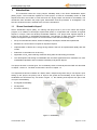


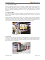
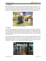
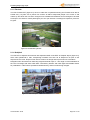

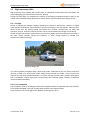
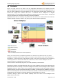


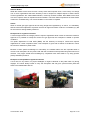
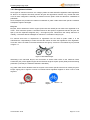
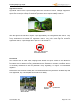
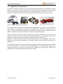


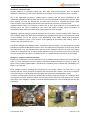

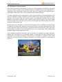
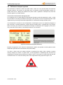


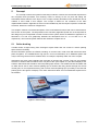


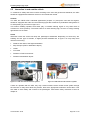
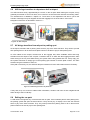
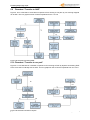
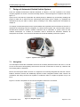

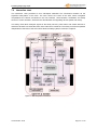


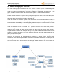
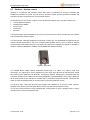
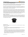
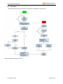
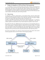

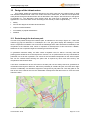
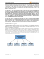


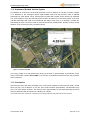

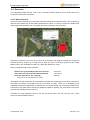


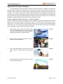

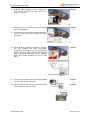

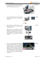

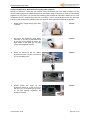


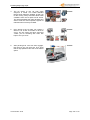


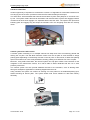

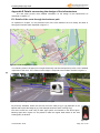

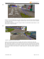
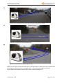

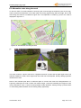


![3.3 Test Report [17 September 2003] PDF](http://vs1.manualzilla.com/store/data/005797517_1-9a96a1d49c489ee795f322ac4fe31348-150x150.png)