1
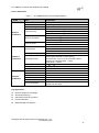
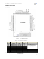
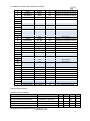
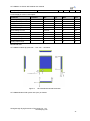
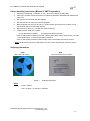
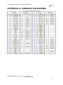
HF-LPB300 Low Power WiFi Module User Manual HF-LPB300 Low Power WiFi Module User Maunal V 1.0 Shanghai High-Flying Electronics Technology Co., Ltd www.hi-flying.com -1- HF-LPB300 Low Power WiFi Module User Manual TABLE OF CONTENTS LIST OF FIGURES ...................................................................................................................................3 LIST OF TABLES.....................................................................................................................................3 HISTORY ..................................................................................................................................................3 PRODUCT OVERVIEW .........................................................................................................................4 General Description ...........................................................................................................................4 Device Features ...............................................................................................................................4 Device Paremeters ...........................................................................................................................5 Key Application .................................................................................................................................5 Hardware Introduction .......................................................................................................................6 Pins Definition...................................................................................................................................6 Electrical Characteristics ..................................................................................................................7 Mechanical Size ...............................................................................................................................8 On-board Chip Antenna....................................................................................................................9 Order Information ...........................................................................................................................10 PACKAGE INFORMATION .................................................................................................................10 Recommended Reflow Profile .........................................................................................................10 Device Handling Instruction (Module IC SMT Preparation) .........................................................11 Shipping Information .......................................................................................................................11 APPENDIX A: 88MW300 PIN MAPING ............................................................................................12 Shanghai High-Flying Electronics Technology Co., Ltd www.hi-flying.com -2- HF-LPB300 Low Power WiFi Module User Manual LIST OF FIGURES Figure 1. HF-LPB300 Demo ................................................................................... 错误!未定义书签。 Figure 2. HF-LPB300 Pins Map .............................................................................................................6 Figure 3. HF-LPB300 Mechanical Dimension........................................................................................8 Figure 4. HF-LPB300 PCB Symbol Size................................................................................................9 Figure 5. Suggested Module Placement Region ...................................................................................9 Figure 6. HF-LPB300 Order Information .............................................................................................10 Figure 7. Reflow Soldering Profile .......................................................................................................10 Figure 8. Shipping Information.............................................................................................................11 LIST OF TABLES Table 1 HF-LPB300 Module Technical Specifications .........................................................................5 Table 2 HF-LPB300 Pins Definition ......................................................................................................6 Table 3 Reflow Soldering Parameter ....................................................................................................10 HISTORY Ed. V1.0 Created on 4-2-2015. Shanghai High-Flying Electronics Technology Co., Ltd www.hi-flying.com -3- HF-LPB300 Low Power WiFi Module User Manual PRODUCT OVERVIEW General Description The HF-LPB300 is a fully self-contained small form-factor, single stream, 802.11b/g/n Wi-Fi module, which provide a wireless interface to any equipment with a Serial/SPI/USB/GPIO interface for data transfer.HF-LPB300 integrate MAC, baseband processor, RF transceiver with power amplifier in hardware and all Wi-Fi protocol and configuration functionality and networking stack, in embedded firmware to make a fully self-contained 802.11b/g/n Wi-Fi solution for a variety of applications. HF-LPB300 support AP+STA wireless networking and support Wi-Fi Direct mode. HF-LPB300 also provides wireless and remote firmware upgrade, which satisfied all kinds of application requirement. HF-LPB300 support wakup-on-wireless feature which make it a very suitable solution for battery applications with excellent power save scheme. The HF-LPB300 employs the world's lowest power consumption embedded architecture. It has been optimized for all kinds of client applications in the home automation, smart grid, handheld device, personal medical application and industrial control that have lower data rates, and transmit or receive data on an infrequent basis. The HF-LPB300 integrates all Wi-Fi functionality into a low-profile, 23.1x32.8x 2.7mm SMT module package that can be easily mounted on main PCB with application specific circuits. Also, module provides built-in antenna, external antenna option. Device Features Single stream Wi-Fi @ 2.4 GHz with support for WEP security mode as well as WPA/WPA2 Fully self-contained serial-to-wireless functionality. Support IEEE802.11b/g/n Wireless Standards Ultra-Low-Power for Battery Applications with Excellent Power Save Scheme Support UART/SPI/USB/PWM/ADC/GPIO Data Communication Interface Support Work As STA/AP/AP+STA/Wi-Fi Direct Mode Support Smart Link Function (APP for smart configuration) Support Wireless (OTA) and Remote Firmware Upgrade Function Support Wakeup-on-Wireless and Wakeup Local Support TLS/SSL and mDNS Protocal Support PCB/External Antenna Option Internal 2MB Flash Inside Single +3.3V Power Supply Smallest Size: 23.1mm x 32.8mm x2.7mm FCC/CE Certificated Shanghai High-Flying Electronics Technology Co., Ltd www.hi-flying.com -4- HF-LPB300 Low Power WiFi Module User Manual Device Paremeters Table 1 Class Wireless Parameters HF-LPB300 Module Technical Specifications Item Parameters Certification Wireless standard Frequency range FCC/CE 802.11 b/g/n 2.412GHz-2.484GHz 802.11b: +16 +/-2dBm (@11Mbps) 802.11g: +14 +/-2dBm (@54Mbps) 802.11n: +13 +/-2dBm (@HT20, MCS7) 802.11b: -93 dBm (@11Mbps ,CCK) 802.11g: -85 dBm (@54Mbps, OFDM) 802.11n: -82 dBm (@HT20, MCS7) External:I-PEX Connector Internal:On-board PCB antenna UART SPI, PWM, GPIO… Others: USB, ADC, RTC… 2.97V~3.63V Peak [Continuous TX]: ~240mA Normal [WiFi ON/OFF, DTIM=100ms]: AP Associate: ~21mA; No-AP Associate:~26mA Wakeup-on-Wireless Mode: ~10mA; Deep Sleep: <100uA -40℃- 85℃ -45℃- 125℃ 23.1mm×32.8mm×2.7mm Transmit Power Receiver Sensitivity Antenna Option Data Interface Operating Voltage Hardware Parameters Software Parameters Operating Current Operating Temp. Storage Temp. Dimensions and Size Network Type Security Mechanisms Encryption Update Firmware Network Protocol User Configuration STA /AP/STA+AP/Wi-Fi Direct WEP/WPA-PSK/WPA2-PSK WEP64/WEP128/TKIP/AES Local Wireless (OTA), Remote IPv4,TCP/UDP/FTP/HTTP,FTTPS,TLS,mDNS AT+instruction set, Web page/ Android/ iOS Smart Link APP tools Key Application Remote equipment monitoring Smart Home/Energy Industrial sensors and controls Home automation Medical/Healthcare devices Shanghai High-Flying Electronics Technology Co., Ltd www.hi-flying.com -5- HF-LPB300 Low Power WiFi Module User Manual Hardware Introduction Pins Definition Figure 1. Table 2 Pin 1,17,32,48 2 3 4 5 6 7 8 9 Describtion Ground JTAG Function JTAG Function JTAG Function JTAG Function JTAG Function GPIO GPIO +3.3V Power HF-LPB300 Pins Map HF-LPB300 Pins Definition Net Name Signal Type GND Power JTAG_TCK I, PU JTAG_TDO O JTAG_TDI I,PU JTAG_TMS I,PU JTAG_nTRST I,PU WAKEUP0 I/O WAKEUP1 I/O DVDD Power Comments JTAG/Debug functional pin, No connect if not use. No connect GPIO7, No connect if not use. GPIO8, No connect if not use. Shanghai High-Flying Electronics Technology Co., Ltd www.hi-flying.com -6- HF-LPB300 Low Power WiFi Module User Manual 10 11 12 13 14 15 16 18 19 20 21 22 23 24 25 26 27 28 29 30 31 33 34 35 36 37 38 39 40 41 42 43 44 45 46 47 GPIO A/D Input 1 A/D Input 2 GPIO GPIO GPIO GPIO GPIO GPIO I2C Interface I2C Interface SPI Data In SPI Interface SPI Interface SPI Data Out +3.3V Power +3.3 Power UART0 UART0 UART0 UART0 GPIO GPIO GPIO Module Reset BOOT0 ADC1 ADC2 RTC_XIN RTC_XOUT BOOT1 N.C UART1_TXD N.C UART1_RXD N.C N.C N.C GPIO24 I2C_SCL I2C_SDA SPI_MISO SPI_CLK SPI_CS SPI_MOSI DVDD N.C DVDD N.C N.C N.C N.C UART0_TX UART0_RTS UART0_RX UART0_CTS nLink nReady nReload N.C EXT_RESETn I/O I/O I/O I/O I/O I/O I/O I/O I/O I/O I/O I I/O I/O O Power GPIO10, No connect if not use. GPIO11, No connect if not use. GPIO12, No connect if not use. GPIO13, No connect if not use. GPIO14, No connect if not use. GPIO15, No connect if not use. No connect GPIO18, No connect if not use. No connect GPIO20, No connect if not use. No connect No connect No connect GPIO24, No connect if not use. GPIO25, No connect if not use. GPIO26, No connect if not use. GPIO27, No connect if not use. GPIO28, No connect if not use. GPIO29, No connect if not use. GPIO30, No connect if not use. No connect Power O I/O I I/O I/O I/O I/O,PU I,PU No connect No connect No connect No connect UART Communication Pin UART Pin (Or RS485 Control) UART Communication Pin UART Communication Pin GPIO43, No connect if not use. GPIO44, No connect if not use. GPIO45, No connect if not use. No connect “Low” effective reset input. Electrical Characteristics Absolute Maximum Ratings: Parameter Condition Storage temperature range Maximum soldering temperature Max. Unit 125 °C 260 °C 0 3.8 V 0 3.3 V 2 KV -45 IPC/JEDEC J-STD-020 Supply voltage Voltage on any I/O pin ESD (Human Body Model HBM) Min. TAMB=25°C Typ. Shanghai High-Flying Electronics Technology Co., Ltd www.hi-flying.com -7- HF-LPB300 Low Power WiFi Module User Manual ESD (Charged Device Model, CDM) TAMB=25°C 500 V Power Supply & Power Consumption: Parameter Condition Operating Supply voltage Min. Typ. Max. Unit 2.97 3.3 3.63 V 250 mA Supply current, peak Continuous Tx 200 Supply current, IEEE PS DTIM=100ms 21 mA Input high voltage VDD*70% VDD+0.4 V Input low voltage -.04 VDD*30% V Input leakage current VDD On 2 uA 5 pF Input capacitance Pullup strength 10 50 uA Pulldowm strength 10 50 uA Analog input range 0 3 V Analog output range 0 3 V Mechanical Size HF-LPB300 modules physical size (Unit: mm) as follows: Figure 2. HF-LPB300 Mechanical Dimension HF-LPB300 Module PCB symbol size (mm) as follows: Shanghai High-Flying Electronics Technology Co., Ltd www.hi-flying.com -8- HF-LPB300 Low Power WiFi Module User Manual Figure 3. HF-LPB300 PCB Symbol Size On-board Chip Antenna HF-LPB300 module support internal on-board chip antenna option. When customer select internal antenna, you shall comply with following antenna design rules and module location suggestions: For customer PCB, RED color region (8.3x18.4mm) can’t put componet or paste GND net; Antenna must away from metal or high components at least 10mm; Antenna can’t be shieldedby any meal enclosure; All cover, include plastic, shall away from antenna at least 10mm; Figure 4. Suggested Module Placement Region High-Flying suggest HF-LPB300 module better locate in following region at customer board, which to reduce the effect to antenna and wireless signal, and better consult High-Flying technical people when you structure your module placement and PCB layout. Shanghai High-Flying Electronics Technology Co., Ltd www.hi-flying.com -9- HF-LPB300 Low Power WiFi Module User Manual Order Information Base on customer detailed requirement, HF-LPB300 series modules provide different variants and physical type for detailed application. Figure 5. HF-LPB300 Order Information PACKAGE INFORMATION Recommended Reflow Profile Figure 6. Reflow Soldering Profile Table 11 Reflow Soldering Parameter NO. Item 1 Reflow Time 2 Peak-Temp Temperature (Degree) Time of above 220 Time(Sec) 35~55 sec 260 max Note: 1. Recommend to supply N2 for reflow oven. 2. N2 atmosphere during reflow (O2<300ppm) Shanghai High-Flying Electronics Technology Co., Ltd www.hi-flying.com - 10 - HF-LPB300 Low Power WiFi Module User Manual Device Handling Instruction (Module IC SMT Preparation) 1. Shelf life in sealed bag: 12 months, at <30℃ and <60% relative humidity (RH) 2. After bag is opened, devices that will be re-baked required after last baked with window time 168 hours. 3. Recommend to oven bake with N2 supplied 4. Recommend end to reflow oven with N2 supplied 5. Baked required with 24 hours at 125+-5℃ before rework process for two modules, one is new module and two is board with module 6. Recommend to store at ≦10% RH with vacuum packing 7. If SMT process needs twice reflow: (1) Top side SMT and reflow (2) Bottom side SMT and reflow Case 1: Wifi module mounted on top side. Need to bake when bottom side process over 168 hours window time, no need to bake within 168 hours Case 2: Wifi module mounted on bottom side, follow normal bake rule before process Note: Window time means from last bake end to next reflow start that has 168 hours space. Shipping Information TAPE BOX Size: 340*340*70 mm Size: 340*340*350 mm (inside) Figure 7. Shipping Information Note: 1 tape = 500pcs 1 box = 5 tapes = 5 * 500 pcs = 2500pcs Shanghai High-Flying Electronics Technology Co., Ltd www.hi-flying.com - 11 - HF-LPB300 Low Power WiFi Module User Manual APPENDIX A: 88MW300 PIN MAPING Shanghai High-Flying Electronics Technology Co., Ltd www.hi-flying.com - 12 -