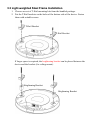
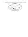
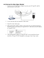
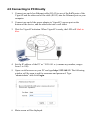
1
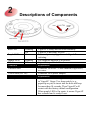
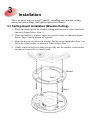
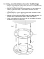
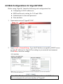
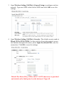
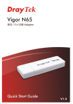
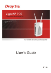
VigorAP 910C 802.11ac Ceiling-mount Access Point Quick Start Guide Version: 1.0 F/W: V1.1.2_RC3 Date: March 10, 2015 Warranty We warrant to the original end user (purchaser) that the router will be free from any defects in workmanship or materials for a period of one (1) year from the date of purchase from the dealer. Please keep your purchase receipt in a safe place as it serves as proof of date of purchase. During the warranty period, and upon proof of purchase, should the product have indications of failure due to faulty workmanship and/or materials, we will, at our discretion, repair or replace the defective products or components, without charge for either parts or labor, to whatever extent we deem necessary tore-store the product to proper operating condition. Any replacement will consist of a new or re-manufactured functionally equivalent product of equal value, and will be offered solely at our discretion. This warranty will not apply if the product is modified, misused, tampered with, damaged by an act of God, or subjected to abnormal working conditions. The warranty does not cover the bundled or licensed software of other vendors. Defects which do not significantly affect the usability of the product will not be covered by the warranty. We reserve the right to revise the manual and online documentation and to make changes from time to time in the contents hereof without obligation to notify any person of such revision or changes. European Community Declarations Manufacturer: Address: Product: DrayTek Corp. No. 26, Fu Shing Road, HuKou Township, HsinChu Industrial Park, Hsin-Chu, Taiwan 303 VigorAP 910C DrayTek Corp. declares that VigorAP 910C is in compliance with the following essential requirements and other relevant provisions of R&TTE Directive 1999/5/EEC, ErP 2009/125/EC and RoHS 2011/65/EU. The product conforms to the requirements of Electro-Magnetic Compatibility (EMC) Directive 2004/108/EC by complying with the requirements set forth in EN55022/Class B and EN55024/Class B. The product conforms to the requirements of Low Voltage (LVD) Directive 2006/95/EC by complying with the requirements set forth in EN60950-1. Federal Communication Commission Interference Statement This equipment has been tested and found to comply with the limits for a Class B digital device, pursuant to Part 15 of the FCC Rules. These limits are designed to provide reasonable protection against harmful interference in a residential installation. This equipment generates, uses and can radiate radio frequency energy and, if not installed and used in accordance with the instructions, may cause harmful interference to radio communications. However, there is no guarantee that interference will not occur in a particular installation. If this equipment does cause harmful interference to radio or television reception, which can be determined by turning the equipment off and on, the user is encouraged to try to correct the interference by one of the following measures: Reorient or relocate the receiving antenna. Increase the separation between the equipment and receiver. Connect the equipment into an outlet on a circuit different from that to which the receiver is connected. Consult the dealer or an experienced radio/TV technician for help. This device complies with Part 15 of the FCC Rules. Operation is subject to the following two conditions: (1) This device may not cause harmful interference, and (2) This device may accept any interference received, including interference that may cause undesired operation. This product is designed for 2.4GHz/5GHz WLAN network throughout the EC region and Switzerland with restrictions in France. The antenna/transmitter should be kept at least 20 cm away from human body. Package Content VigorAP Bracket (for ceiling-mount) T-Rail Mounting Kits Screws Quick Start Guide CD RJ-45 Cable (Ethernet) Screws (for wall-mount) The type of the power adapter depends on the country that the router will be installed: UK-type power adapter EU-type power adapter USA/Taiwan-type power adapter AU/NZ-type Power Adapter Descriptions of Components LED LED Blue LED Purple LED Status Blinking Off On Orange LED Off Blinking Off Interface Ethernet Port Power Jack (DC IN) Hole Factory Reset Factory Reset Explanation VigorAP is ready and can work normally. VigorAP is not ready or fails. Power adapter is plugged in and VigorAP is initiating. The firmware upgrade is in process. VigorAP is powered off. Explanation Connecter for xDSL / Cable modem (Giga level) or router. Connecter for a power adapter. Explanation Restore the default settings when any error occurs in VigorAP. Usage: Use sharp article (e.g., paperclip or pin) to insert into the hole and keep for more than 10 seconds. Then VigorAP will restart with the factory default configuration. When purple LED is On again, it means VigorAP has restarted and is ready to use. Installation There are three ways to install VigorAP, installing onto wooden ceiling, cement or hard ceilings, and light-weighted steel frame. 3.1 Ceiling-mount Installation (Wooden Ceiling) 1. Place the bracket under the wooden ceiling and fasten two screws firmly (as shown in Figure below, Step 1). 2. When the bracket is in place, fasten two screws firmly (as shown in Figure below, Step 2) on the bottom of VigorAP. 3. Make the device just below the bracket. Put the screws installed in Step 2 on the holes of the bracket (as shown in Figure below, Step 3). 4. Gently rotate the device to make screws slide into the notches of the bracket and move forward till it is firmly fixed. Bracket Step 3 Step 1 Step 2 3.2 Ceiling-mount Installation (Cement or Hard Ceilings) 1. Place the bracket under the wooden ceiling and fasten two turnbuckles firmly (as shown in Figure below, Step 1). 2. Make the screws pass through the bracket and insert into the turnbuckles (as shown in Figure below, Step 2). Fasten them to offer more powerful supporting force. 3. When the bracket is in place, fasten two screws firmly (as shown in Figure below, Step 3) on the bottom of VigorAP. 4. Make the device just below the bracket. Put the screws installed in Step 3 on the screw holes of the bracket (as shown in Figure below, Step 4). 5. Gently rotate the device to make screws slide into the notches of the bracket and move forward till it is firmly fixed. Step 1 Bracket Step 4 Step 2 Step 3 3.3 Light-weighted Steel Frame Installation 1. Choose one set of T-Rail mounting kits from the bundled package. 2. Put the T-Rail brackets on the holes of the bottom side of the device. Fasten them with suitable screws. T-Rail Bracket T-Rail Bracket If larger space is required, the heightening bracket can be placed between the device and the bracket (for ceiling mount). Heightening Bracket Heightening Bracket 3. Use the T-Rail brackets to fasten the device on Light-weighted Steel Frame. Connection and Configuration 4.1 Notifications for Hardware Connection If required, remove the protective cap of VigorAP to create extra space for the cables to pass through. Connect VigorAP to Vigor router (via LAN port) with Ethernet cable. Connect VigorAP to PoE switch (via LAN port) with Ethernet cable. For connecting with PoE switch, do not connect the power adapter. VigorAP will get the power from the switch directly. 4.2 Connect to Vigor Router with AP Management VigorAP 910C can be connected to Vigor router with AP management (such as Vigor2860 series, Vigor2925 series). Then, VigorAP 910C can be accessed through Vigor router for advanced web page configuration. 1. Connect one end of the power adapter to power port of VigorAP, and the other side into a wall outlet. 2. Access into the web user interface of Vigor router. Here we take Vigor2860 as an example. Open Central AP Management>>Status. 3. Locate VigorAP910 C. Click the IP address assigned by Vigor router to access into web user interface of VigorAP 910C. 4. After typing username and password (admin/admin), the main screen will be displayed. 4.3 Connect to Vigor Router without AP Management 1. Connect one end of the power adapter to power port of VigorAP, and the other side into a wall outlet. 2. Access into the web user interface of Vigor router. Here we take Vigor2830 as an example. Open External Devices. 3. Check the box of External Device Auto Discovery and click OK. When the the IP address assigned by Vigor router appears, click it to access into web user interface of VigorAP 910C. 4. After typing username and password (admin/admin), the main screen will be displayed. 4.4 Connect to Non-Vigor Router 1. Connect one end of the power adapter to power port of VigorAP, and the other side into a wall outlet. 2. Access into the web user interface of the router. 3. Open the router status page. 4. Find out the MAC address which is same as the one provided and stated on the label pasted on the bottom of VigorAP 910C. And, find out the IP address of VigorAP 910C. 5. After getting the IP address of VigorAP 910C, access into the web user interface of VigorAP 910C through the web page of non-Vigor router. 4.5 Connecting to PC Directly 1. Connect one end of an Ethernet cable (RJ-45) to one of the LAN ports of the VigorAP and the other end of the cable (RJ-45) into the Ethernet port on your computer. 2. Connect one end of the power adapter to VigorAP’s power port on the bottom of the device, and the other side into a wall outlet. 3. Wait for VigorAP initiation. When VigorAP is ready, the LED will blink in blue. 4. Set the IP address of the PC as “192.168.1.x (x means any number, ranges from 3 to 100). 5. Open a web browser on your PC and type http://192.168.1.2. The following window will be open to ask for username and password. Type “admin/admin” and click Login. 6. Main screen will be displayed. 4.6 Web Configurations for VigorAP 910C Before using VigorAP, finish the following web configuration first. Configuring LAN IP address(es) SSID and Security setting for 2.4G and 5GHz. Administrator’s name and password. Time and date. 1. Open main screen of VigorAP 910C. 2. Open LAN>>General Setup. Type the IP address (assigned by DHCP server or static IP address) for VigorAP according to your network environment. Click OK to save the settings. Note: If the IP address has been modified, use the new LAN IP address for accessing into the web user interface of VigorAP. 3. Open Wireless Setting (2.4GHz)>>General Setup to configure wireless network. Type new SSID in the field of SSID1 and click OK to save the settings. 4. Open Wireless Setting (2.4GHz)>>Security. The default security mode is Mixed (WPA+WPA2)/PSK. For the wireless client who wants to access into Internet through such router, please input the default PSK value for connection. Click OK to save the settings. Default Pre-Shared Key (PSK) with 13 ASCII characters is provided and stated on the label pasted on the bottom of VigorAP. 5. Open Wireless Setting (5GHz)>>Security. The default security mode is Mixed (WPA+WPA2)/PSK. For the wireless client who wants to access into Internet through such router, please input the default PSK value for connection. Click OK to save the settings. 6. Now, you have finished the basic configuration of VigorAP. Note that for the communication, all wireless devices must support the same encryption bit length and share the same key. If WEP mode is selected, only one of four preset keys can be selected at one time. Contacting DrayTek If the router still cannot work correctly after trying many efforts, please contact your dealer for further help right away. For any questions, please feel free to send e-mail to [email protected]. Safety Instructions Read the installation guide thoroughly before you set up the device. The modem is a complicated electronic unit that may be repaired only be authorized and qualified personnel. Do not try to open or repair the modem yourself. Do not place the modem in a damp or humid place, e.g. a bathroom. The modem should be used in a sheltered area, within a temperature range of +5 to +40 Celsius. Do not expose the modem to direct sunlight or other heat sources. The housing and electronic components may be damaged by direct sunlight or heat sources. Do not deploy the cable for LAN connection outdoor to prevent electronic shock hazards. Keep the package out of reach of children. When you want to dispose of the modem, please follow local regulations on conservation of the environment.