1
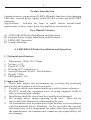
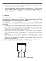
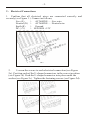
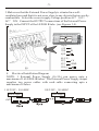
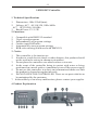
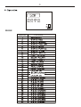
YG-LED101B
Multi-color LED Lamp
USER MANUAL
.1.
Product Introduction :
System structure: comprising of LED101B multi-function color-changing
LED tube, external power supply (with ON/OFF switch) and LED101KT
controller.
Applications:
Suitable for large or small indoor architectural
applications, such as: stage, disco, bar, nightclub, restaurant, etc
User Manual Contents:
A)
B)
C)
D)
LED101B (LED tube) Installation and Operation
External Power Supply Installation and Operation
LED101KT Operation
Trouble Shooting
A LED101B (LED tube) Installation and Operation
1 - Technical specifications
1.
2.
3.
4.
5.
6.
7.
Dimensions: 1000×50×75mm
Voltage: +12V
Power: P≤12W
IP rating: IP33 (interior use)
Average lifespan: 50,000~100,000 hours
Weight: 1.8Kg
LED quantity: 144
2 Important Note
1. Please help protect the environment by recycling the packaging
material that this product was delivered with.
2. Carefully read this user manual and keep it safe for future reference.
3. DO NOT install this equipment close to strong magnetic fields or
objects carrying high voltages.
4. Installation should be carried out by a qualified professional.
5. We strongly advise against opening of the unit. There are no
serviceable parts that may be maintained by the user.
6. All components used in production of this product are in accordance
with International Safety Standards. In the event that the user has
substituted any of the components for others than those supplied by
the manufacturer, the manufacturer cannot accept responsibility for
any damages.
.2.
7.
8.
In the event of any serious operating problem, stop using the unit
immediately and contact your dealer.
The maximum load current of the power cable is 16A. One External
Power Supply can be connected to 16× LED101B tubes in series. If
the quantity of tubes exceeds 16, then an extra External Power Supply
must be added for every 16 tubes.
3 Structure
The LED101B is comprised of LEDs of the three primary colors Red,
Green & Blue, a main PC board, a strong aluminum alloy base frame with
mounting brackets and an External Power Supply.
1. Signal IN: low voltage signal input, connect the Signal IN from one
LED101B tube to the Signal OUT of the previous tube or the LED101KT
controller.
2. Signal OUT: low voltage signal output, connect the Signal OUT from
one LED101B tube to the Signal IN of the next tube. If there are no
further tubes to be connected, the Signal OUT connector of the last
tube must be sealed to protect against humidity.
3. Mains IN: connect the Mains IN from one LED101B tube to the Mains
OUT of the previous tube or the Mains OUT from the External Power
Supply.
4. Mains OUT: connect the Mains OUT from one LED101B tube to the
Mains IN of the next tube. If there are no further tubes to be
connected, the Mains OUT connector of the last tube must be sealed to
protect against humidity.
5. Mounting brackets: used to fix the LED101B tube to a rigid surface
6. Earth cable: used to connect the equipment to Earth
.3.
4 Installation
1. Testing the LED tube: connect the LED101B tube to the power supply
without connecting the signal cable. If the LED101B tube turns on and
the color seen is white, the tube is functioning correctly.
2. Testing the LED tubes and controller: connect the signal cable and
turn on the controller. Press the MODE key and select TEST MODE,
followed by pressing the SETUP key. The display will show IS
CONNECT OK? The tubes will light up red if all connections are
correct.
3. Setting the LED101B: press the MODE key and select ADDRESS
MODE, press the SETUP key. The display will show INITIALIZING
ADDR WAITING. After 2/3 seconds the display will show OK
DONE, indicating that setup is completed.
4. Selecting LED101B program: press the MODE key and select the
desired program.
(Note: these steps must be followed every time the LED101B is setup in a
different location or if the order or number of the LED101B tubes is
changed. If there is no change to the LED101B arrangement, then user
may proceed immediately to step 4 when operating.
B External Power Supply Installation and Operation
WARNING
1.
The maximum load current of the power cable is 16A. One
External Power Supply can be connected to 16×LED101B tubes in series.
If the quantity of tubes exceeds 16, then an extra External Power Supply
must be added for every 16 tubes
2. The External Power Supply will give out heat, it is advisable to place
the External Power Supply in a position that will allow the heat to
disperse easily, i.e. in a position that has good air circulation.
3. DO NOT place easily combustible objects on or close to the External
Power Supply.
4. The External Power Supply is NOT RESISTANT, please do not
operate outdoors.
5. This External Power Supply is 110V/220V, before use, please select
the correct power supply voltage.
1
Technical Specifications
1. Dimensions: 200x50x110 (mm)
2. Rated Voltage: 110V/220V 50/60Hz
Maximum Output Current: 16.5A
.4.
2 - Electrical Connections
1. Confirm that all electrical wires are connected correctly and
securely (see Figure 1.) Connect as follows;
Live (L)
>
AC MAINS......Live wire
Neutral (N) >
AC MAINS......Neutral wire
Earth (E)
>
Ground
DC (+V)
> LED101B +12V
2.
Loosen the screws to each electrical connection (see Figure
2a). Position each of the U-shaped connectors in the correct position
(see Figure 2b) Push the U-shaped connector into place under the
washer (see Figure 2c). Tighten the fastening screws (see Figure 2d).
.5.
3.Make sure that the External Power Supply is situated in a wellventilated area and that it is not on or close to any objects that are easilycombustible. Select the correct supply Voltage position AC? 10V /
AC? 20V. Connect the OUTPUT connections of the External Power
Supply to the INPUT of the LED101B tube. (see Figures 3,4).
Input:
L
火线
零线
地线
N
输 出端 :
+V
棕色
蓝色
GND
黄 绿色
4. Electrical Installation Diagram
NOTE: 1 External Power Supply (16.5A) can power upto a
maximum of 16 LED101B tubes. The External Power Supply output
supplies two power cables with each cable connecting upto a
maximum of 8 tubes.
110/220V,50/60HZ
110/220V,50/60HZ
Power
supply
开关电源
Power
supply
开关电源
+12.5V
+12.5V
.6.
LED101KT Controller
1 Technical Specifications
1. Dimensions: 180x125x49(mm)
2. Voltage: AC? 00/110/120, 50Hz/60Hz
AC? 10/230/240, 50/60Hz
3. Rated Power: P≤1.5W
2 Functions
1. Compatible with DMX512 standard
2. 38 pre-stored programs
3. Independantly set program settings
4. Connect upto 4000 tubes
5. Automatically store program settings
6. RGB color-mixing (when used with DMX512)
3 - Notice
1.
2.
3.
4.
5.
6.
This controller is for interior use
In order to avoid electric shock or other dangers, this product should
not be used in the rain or in a damp environment.
Do not place the controller on a metal surface or in water.
In the event of the controller being in contact with water or being
positioned on a metal surface, immediately turn off the power supply.
Do not use this controller in a dusty environment and make sure that
the product is cleaned at regular intervals.
DO NOT OPEN THE CONTROLLER There are no parts which can
be maintained by the customer.
In the unlikely event of any malfunction, please contact your supplier
7.
.
4 Product Explanation
.7.
1.LCD screen:indicate current working mode, program, settings
2.MODE:select the desired working mode or program
3.SETUP: set the settings in currently selected program (time interval /
speed / strobe / tube quantity)
4. UP: move “UP” through the SETUP options
5. DOWN: move “DOWN” through the SETUP options
6. POWER ON/OFF:turn the LED101KT controller ON & OFF. When
the unit is turned off the current settings will be automaticallystored.
7. DMX IN:connect the DMX512 signal cable
8. DMX OUT: connect the DMX512 signal cable to the next unit
9. OUTPUT:connect to the signal of the first LED101B tube
10. DC INPUT: connect the 12V/500mA DC Power Supply
VII. STRUCTURE MAP OF CONTROLLER:
Display
Power
Supply
12V
GND
CPU
GND A B
Keyboard
5 Data Control Cable
LED control Socket
.8.
MODE
Number
Function
.9.
Number
Function
SETUP
2. To adjust according to the SETUP button:
Number
Show Data
1
2
3
4
5
FLASH
INVERVAL
RUN SPEED
TUBE QTY
DMX ADDR
Illustration
Max
100
100
100
Over 4000
255
Min
0
0
0
0
1
UP
Move “UP” through the SETUP options. Press SETUP to confirm.
DOWN
Move “DOWN” through the SETUP options. Press SETUP to confirm.
DMX ADDRESSING
>press the MODE key and select DMX MODE
>press the SETUP key
>use the UP / DOWN key to set the DMX CHANNEL of the MODE
option. (The 4 Channel arrangement is MODE,SPEED,INTERVAL,
FLASH / 0 ,RED,GREEN,BLUE)
>press the SETUP key
7 Installation Diagram
.10.
X. INSTALLATION Map:
Tube 1
Power Line
Tube 2
Tube N
Data cable
LED KT Controller
DMX512 data cable
DMX-512 Controller
8 DMX512 CONTROL MODE
MODE 1:
MODE 2:
MODE, SPEED, INTERVAL, FLASH
0 , RED, GREEN, BLUE
When the Channel 1 fader on the DMX512 controller is NOT at 0
(Channel 1 is not at its lowest value) then the DMX512 control mode will
be MODE 1. When the Channel 1 fade on the DMX512 controller is 0
(Channel 1 is set at its lowest value) then the DMX512 control mode will
be MODE 2.
The DMX512 address can be set between 1 and 255, with 1 as the default
DMX512 address.
MODE 1:
Channel 1: DMX512 values (0~255)
Note: for values 0~47 (static colors) Channels 2 & 3 have no function.
9 DMX512 ADDRESSING
¾
Connect the LED101KT to the power supply
¾ Use the MODE key to select DMX512 mode
¾ Press SETUP, LCD screen will display the
DMX512 ADDRESS
¾ Using the UP / DOWN keys select the correct
DMX512 Address
¾ Press the SETUP key
.11.
Value
0~5
6~11
12~17
18~23
24~29
30~35
36~41
42~47
48~53
54~59
60~65
66~71
72~77
78~83
84~89
90~95
96~101
102~107
108~113
114~119
120~125
126~131
132~137
138~143
144~149
150~155
156~161
162~167
168~173
174~179
180~185
186~191
192~197
198~203
204~209
210~215
216~221
222~255
Statement
.12.
2、Second channel control the speed:
Speed
Value
0
255
0
100
3、Third channel control the time interval:
4、Fourth channel control the strobe:
Value
Strobe
0
255
0
100
.13.
Trouble shooting
Situation
No light output
(all tubes)
Cause
1、power-plug has no power
1、replace the power-socket
2、led101KT has no signal output
2、replace the controller
3、replace the first tube
4、change the program mode
3、The first tube is damaged
4、Controller is in black mode
1、controller quantity or tubes
First section of tubes
lit, rest of tubes black
Solution
set incorrectly
2、loose or broken power or
signal cable at first black tube
3、first black tube is damaged
1、set the correct amount of
tubes.
2、reconnect the power and
signal plugs orreplace with a
working tube
3、replace the damaged tube
with a good tube
Center or tube black, PCB at black portion
is damaged
rest of tube lit
Replace the LED101b
tube
Portion of tube`s color
PCB LEDs damaged
is incorrect or black
Replace the damaged
LEDs
Unstable operation
not responding to
controlsignal
1,LED101KT is
damaged
2,Local signal interference
3,power load is exceeded,
power cable damage
1,replace the controller
2,remove source of signal
interference
3,increase the number of
connections tomains power
supply,reduce the power load
by reducing the quantityof
tubes on mainspower
connections
Replacing Damaged LEDs
1. Locate the position of the damaged Led. Determine the color of the
damaged LED (e.g. when the tube is in WHITE mode, if one section is purple,
then the GREEN LED is damaged)
2. Open the tube at both ends
3. Using an electric soldering iron, remove the LED PCB's down-lead.
Note the corresponding position and color of the LED PCB's down-lead
(BLACK EARTH / RED(thin) - +12V / WHITE A+ / RED (thick)
B-)
4. Remove the LED PCB from the tube
5. Use a soldering iron to remove the damaged LEDs
6. Replace with good LEDs and solder into place. Make sure that the LED
+ve pin (long pin) is soldered into the +ve hole on the LED PCB.
7. Cut-off any excess pin that sticks out of the underside of the PCB.
8. Replace the PCB into the tube.
.14.
ELECTRICAL DIAGRAM
POWER IN
SIGNAL OUT
(DC+12V)