1
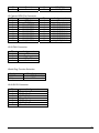
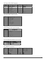
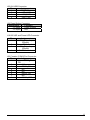
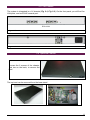
Kilin-6006 Series Communication Appliance User′s Manual Revision: 1.2 CE This certificate of conformity of KILIN-6006 series with actual required safety standards in accordance with 89/366 ECC-EMC Directive and LVD 73/23 ECC UL This product meets all safety requirements per UL60950 standard. Portwell Inc. 4F, No. 186, Jian-Yi Rd., Chung-Ho City 235 Taipei, Taiwan Headquarter: +886-2-7731-8888 FAX: +886-2-8227-1109 http://www.portwell.com.tw Email: [email protected] Table of Contents Chapter 1 Introduction......................................................................................................... 2 1.1 About This Manual ................................................................................................ 2 1.2 Manual Organization............................................................................................. 2 1.3 Technical Support Information .............................................................................. 2 1.4 Board Layout ........................................................................................................ 3 1.5 System Block Diagram.......................................................................................... 4 1.6 Product Specification ............................................................................................ 5 Chapter 2 Getting Started............................................................................................. 6 2.1 Included Hardware................................................................................................ 6 2.2 Before You Begin.................................................................................................. 6 2.3 Hardware Configuration Setting ............................................................................ 7 2.4 The Chassis ........................................................................................................ 13 2.5 Open the Chassis ............................................................................................... 13 2.6 Installing and Removing Hard Disk.................................................................. 14 2.7 Remove and Install DIMM................................................................................... 15 2.8 Use a Client Computer........................................................................................ 16 Chapter 3 Boot-Loader Setting ......................................................................... 18 3.1 Boot-Loader Information.................................................................................... 18 3.2 Key Commands in Boot-Loader......................................................................... 19 3.3 Hardware Monitor in Boot-Loader...................................................................... 20 3.4 Boot-Loader Update .......................................................................................... 21 KILIN-6006 Series User’s Manual 1 Chapter 1 Introduction 1.1 About This Manual This manual contains all required information for setting up and using the Kilin-6006 series. Kilin-6006 provides the essential platform for delivering optimal performance and functionality in the value communications appliance market segment. This manual should familiarize you with Kilin-6006 operations and functions. Kilin-6006 series provide up to 5 on-board Ethernet ports to serve communication applications like Firewall, requiring 5 Ethernet ports to connect external network (internet), demilitarized zone and internal network. Kilin-6006 series overview: Kilin-6005 series overview: Octeon MIPS 64 31xx up to 2 Cores Of 300/400/500 MHz Memory: Two DDR2 DIMM slots and up to 4G Three Gigabit Ethernet interfaces Two 10M/100M Ethernet interfaces Independent management console(RS232) and Ethernet interface for MIPS64 system One PCI golden finger for PCI device connectivity. Two SATA Hard disks 1.2 Manual Organization This manual describes how to configure your Kilin-6006 system to meet various operating requirements. It is divided into three chapters, with each chapter addressing the basic concept and operation of this system. Chapter 1: Introduction. This section describes how this document is organized. It includes brief guidelines and overview to help find necessary information. Chapter 2: Hardware Configuration Setting and Installation. This chapter demonstrated the hardware assembly procedure, including detailed information. It shows the definitions and locations of Jumpers and Connectors that can be used to configure the system. Chapter 3: Operation Information. This section provides illustrations and information on the system architecture and how to optimize its performance. Any updates to this manual, would be posted on the web site: http://www.portwell.com.tw/products/ca.html 1.3 Technical Support Information Users may find helpful tips or related information on Portwell's web site: http://www.portwell.com.tw a direct contact to Portwell's technical person is also available. For further support, users may also contact Portwell’s headquarter in Taipei or local distributors. Taipei Office Phone Number: +886-2-7731-8888 KILIN-6006 Series User’s Manual 2 1.4 Board Layout Figure 1-1 KILIN-6006 Series User’s Manual Board Layout of Kilin-6006 M/B 3 1.5 System Block Diagram Figure 1-2 KILIN-6006 Series User’s Manual Kilin-6006 Basic Block Diagram 4 1.6 Product Specification Feature Detailed Description Processor Cavium Octeon CN31xx Single and Dual MIPS64, L2 Cache 256KB, Frequency 500Mhz. Memory Support 2x 200pin DDR2 SODIMM sockets support DDR2 400/533 Max. Capacity up to 4GB ( 2GB 2 Rank DIMM)On-board 3 Bypass Ethernet ports Two Gigabit Ethernet ports with 1 bypass segments from RGMII interface of Octeon CN31xx with Marvell 88E1145 Ethernet PHY. 4 CF slot One CF slot for Operating system One CF slot for log and backup (Optional) 5 6 SATA channels USB 7 Ethernet ports One internal SATA channel for HDD connection Support USB 2.0. 10/100M management port (copper) using Intel 82551QM 3 Gigabit Ethernet port (copper) from 31XX RGMII on CPU board. 8 H/W Reset and Load Factory Default There is a pin-header for H/W reset There is a pin-header on board to connect to additional push button for F/D (Load Factory Default). 9 LED 1 * Power LED (Green) – in front 1 * Data Activity (Red). – in front 10 System Monitoring Feature The system shall monitor CPU & System Temperature and operating voltage 11 Watch Dog Timer The WDT support 8 time-out intervals from 0.5 sec/Min to 64 sec/Max by s/w programming. 12 System Dimension 428mm / 16.8” (W) x 44mm / 1.7” (H) x 255 mm/ 10.1”(D) 13 Environmental requirements Storage temp.: -40°C to 80°C Operating temp.: 5°C to 60°C. Humidity: 5 to 95% RH 1 2 KILIN-6006 Series User’s Manual 5 Chapter 2 Getting Started This section describes how the hardware installation and system settings should be done. 2.1 Included Hardware The following hardware is included in package: Kilin-6006 Communication Appliance System Board One null serial port cable 2.2 Before You Begin To prevent damage to any system board, it is important to handle it with care. The following measures are generally sufficient to protect your equipment from static electricity discharge: When handling the board, use a grounded wrist strap designed for static discharge elimination and touch a grounded metal object before removing the board from the antistatic bag. Handle the board by its edges only; do not touch its components, peripheral chips, memory modules or gold contacts. When handling processor chips or memory modules, avoid touching their pins or gold edge fingers. Restore the communications appliance system board and peripherals back into the antistatic bag when they are not in use or not installed in the chassis. Some circuitry on the system board can continue operating even though the power is switched off. Under no circumstances should the Lithium battery cell used to power the real-time clock be allowed to be shorted. The battery cell may heat up under these conditions and present a burn hazard. WARNING! 1. "CAUTION: DANGER OF EXPLOSION IF BATTERY IS INCORRECTLY REPLACED. REPLACE ONLY WITH SAME OR EQUIVALENT TYPE RECOMMENDED BY THE MANUFACTURER. DISCARD USED BATTERIES ACCORDING TO THE MANUFACTURER’S INSTRUCTIONS" 2. This guide is for technically qualified personnel who have experience installing and configuring system boards. Disconnect the system board power supply from its power source before you connect/disconnect cables or install/remove any system board components. Failure to do this can result in personnel injury or equipment damage. 3. Avoid short-circuiting the lithium battery; this can cause it to superheat and cause burns if touched. 4. Do not operate the processor without a thermal solution. Damage to the processor can occur in seconds. 5. Do not block air vents. Minimum 1/2-inch clearance required. KILIN-6006 Series User’s Manual 6 2.3 Hardware Configuration Setting 2.3.1 Kilin-6006 System Front Panel 5 2 3 1 4 6 7 1 RGMII Gigabit Ethernet 5 System Power LED 2 PCI-3210/100 Ethernet 6 Hard Disk LED 3 PCI-32 10/100 Ethernet 7 Reset button 4 Console from Octeon KILIN-6006 Series User’s Manual 7 2.3.2 Kilin-6006 System Board Jumper In general, jumpers on Kilin-6006 system board are used to select options for certain features. Some of the jumpers are configurable for system enhancement. The others are for testing purpose only and should not be altered. To select any option, cover the jumper cap over (Short) or remove (NC) it from the jumper pins according to the following instructions. Here NC stands for “Not Connected”. KILIN-6006 Series User’s Manual 8 Location of Jumpers MEB-3931VL Jumper Setting The jumper settings are schematically depicted in this manual as follows: Connector Table Function Descriptions Connector Reference J1 Cavium GPIO pin Connector J2 8 bit GPIO connector J3/J9 System Fan / CPU Fan J4/J33 DDR2 SO-DIMM Connector J5 Watch Dog Enable Connector J6/J8 SATA Connector J7 Case Open and Temperature Connector J10 Cavium CPU JTAG Connector J12 Lattics CPLD JTAG Connector J13 DC power +5V and +12V input Connector J14 PICMG Gold finger interface J16/J18 Load Default Button and Connector J20 Bypass state LED Connector J21 COM2 Port Connector J22 USB Connector J26 Reset Button Connector J19/J25 Power / HD LED Connector J28/J30/J31 10/100/1000 LAN RJ45 Connector J27/J29 10/100 LAN RJ45 Connector J23 Console Port Connector J32 Power Jack DC Input J11/J34 Compact Flash Connector J1 Cavium bootloader selection Pin Signal Description 1-2 Short Normal bootloader mode (Default) 1-2 Open Fail-safe bootloader mode J1 Cavium GPIO Pin Connector Assignment Pin 1 OCT_GPIO_0 3 OCT_GPIO_1 5 OCT_GPIO_4 7 OCT_GPIO_5 9 OCT_GPIO_8 11 OCT_GPIO_9 13 TWS_SCL 15 TWS_SDA KILIN-6006 Series User’s Manual Pin 2 4 6 8 10 12 14 16 Assignment Ground OCT_GPIO_10 OCT_GPIO_11 OCT_GPIO_20 OCT_GPIO_21 OCT_GPIO_22 OCT_GPIO_23 MDI_MDC 9 17 19 Ground Ground J2 Cavium GPIO Pin Connector Assignment Pin 1 VDD_5V 3 VDD_5V 5 8Bit_IOGP07 7 8Bit_IOGP06 9 8Bit_IOGP05 11 8Bit_IOGP04 13 8Bit_IOGP03 15 8Bit_IOGP02 17 8Bit_IOGP01 19 8Bit_IOGP00 18 20 MDI-MDIO LOAD_DF Pin 2 4 6 8 10 12 14 16 18 20 Assignment Ground Ground 8Bit_EXT_DIO07 8Bit_EXT_DIO06 8Bit_EXT_DIO05 8Bit_EXT_DIO04 8Bit_EXT_DIO03 8Bit_EXT_DIO02 8Bit_EXT_DIO01 8Bit_EXT_DIO00 J3/J9 FAN Connector Assignment N/A Fan Input VDD_12V Ground Pin 1 2 3 4 Watch Dog Function Selection Assignment 1-2 Short 1-2 Open Function Enable WDT (Default) Disable WDT J6/J8 SATA Connector Pin 1 2 3 4 5 6 7 Assignment Ground SATA_Tx_P SATA_Tx_N Ground SATA_Rx_N SATA_Rx_P Ground KILIN-6006 Series User’s Manual 10 J10 Cavium CPU JTAG Connector Pin 1 3 5 7 9 11 13 Assignment EJTAG_TRST# JTAG_TDI EJTAG_TDO JTAG_TMS JTAG_TCK EJTAG_Reset# EJTAG_DINT Pin 2 4 6 8 10 12 14 Assignment Ground Ground Ground Ground Ground N/A VDD_3V J12 Lattics CPLD JTAG Connector Pin 1 2 3 4 5 6 7 8 Assignment VDD_5V CPLD_TDO CPLD_TDI N/P N/A CPLD_TMS CPLD_TCK Ground J13 DC Power 5V/12V Input Connector Pin 1 2 3 4 5 6 Assignment VDD_5V VDD_5V Ground Ground Ground VDD_12V J16/J18 Load Default Button and Connector Assignment 1-2 Short 1-2 Open Function Load Default N/A J21 COM2 Port Connector Pin 1 3 5 7 9 Assignment N/C RS232_RX RS232_TX N/C Ground KILIN-6006 Series User’s Manual Pin 2 4 6 8 10 Assignment N/C RS232_RTS RS232_CTS N/C N/A 11 J22/J24 USB Connector Assignment Pin USB_GND 1 2 USB_DATA+ 3 USB_DATA4 USB_PWR J26 Reset Button Connector Assignment Function 1-2 Short Reset System 1-2 Open N/A J19/J25 H/D and Power LED Connector Pin 1 2 3 4 Assignment VDD_5V (pull up 330ohm) Power LED Active Low VDD_5V (pull up 330ohm) H/D LED Active Low J23 Console (COM1)Port Connector Assignment Pin RS232_R 1 TS 2 3 4 5 6 7 8 N/C RS232_TX N/C N/C RS232_RX N/C RS232_CTS KILIN-6006 Series User’s Manual 12 2.4 The Chassis The system is integrated in a 1U chassis (Fig. 2-1, Fig. 2-2). On the front panel you will find five LAN ports, and one RJ45 console port. Kilin-6006 Fig. 2-1 Front view of the chassis Fig. 2-2 Rear view of the chassis 2.5 Open the Chassis Loosen the 6 screws of the chassis, rest two on the back, to remove the lead The top lead can be removed from the base stand KILIN-6006 Series User’s Manual 13 2.6 Installing and Removing Hard Disk The system has an internal drive bay for one 2.5" SATA hard disk drive. If the HDD is not pre-installed, you can install it by yourself. Installing a SATA Hard Drive into a SATA Drive Carrier 1. Insert the SATA hard drive into the hard-drive carrier. 2. Attach the four screws to secure the hard drive to the hard-drive carrier. KILIN-6006 Series User’s Manual 14 2.7 Remove and Install DIMM Follow these steps to upgrade RAM module: 1. Obliquity inserts the DIMM into the socket and depresses DIMM until the retaining clips back in place Follow these steps to remove a DIMM: 1. Pull the retaining clips of DIMM socket simultaneously to unlock the DIMM KILIN-6006 Series User’s Manual 15 2. Remove the DIMM from the socket 2.8 Use a Client Computer Connection Using Hyper Terminal To access Kilin-6006 via the console, Hyper Terminal is one of many choices. Follow the steps below for the setup: Note: Terminal software may need to update for correct console output. 1. Execute HyperTerminal under C:\Program Files\Accessories\HyperTerminal 2. Enter a name to create new dial 3. For the connection settings, make it Direct to Com1. KILIN-6006 Series User’s Manual 16 4. Please make the port settings to Baud rate 115200, Parity None, Data bits 8, Stop bits 1 5. Turn on the power of Kilin-6006 system, after following screen was shown: This is the end of this section. If the terminal did not port correctly, please check the previous steps. . KILIN-6006 Series User’s Manual 17 Chapter 3 Boot-Loader Setting 3.1 Boot-Loader Information After you boot the system, the Boot-Loader information (as figure below) will appear on the screen. Key messages will be shown on screen as following U-boot : Display the U-boot version and built time DRAM Information : Detect the DRAM clock and size CF card Profile : Detect the CF card model and capacity LAN : Display LAN port status of Kilin-6006 system Help menu in Boot Loader “Help” menu is available handily by typing “help” KILIN-6006 Series User’s Manual 18 3.2 Key Commands in Boot-Loader Fatls – Function: List files in directory When to use: To find the file in the CF card as “dir” command Usage : fatls <interface> <dev[:part]> [directory] Ex: #fatls ide 0 Fatload – Function: Load binary file from a DOS file system When to use: Update boot-loader or running OS or running test tool Usage : fatload <interface> <dev[:part]> <addr> <filename> [bytes] KILIN-6006 Series User’s Manual 19 Ex: #fatload ide 0 100000 ipfw Bootoct – Function: Boot from an Simple Executive ELF image in memory When to use: Running Simple Executive Usage : bootoct <addr> coremask=**** Ex: bootoct 100000 coremask=ffff Bootoctl – Function: Boot from a Linux ELF image in memory When to use: When you need to execute Linux image Usage : bootoctl <addr> coremask=**** Ex: bootoctl 5000000 coremask=ffff Hmd – Function: Sensors display (Portwell) When to use: When you want to monitor system H/W status Usage : #hmd Run – Function: Run commands in an environment variable When to use: Want to update boot-loader or running Linux Usage : run linux_cf or run bootloader_update Reset – Function: Perform reset of the CPU When to use: Want to warm boot the system Usage : reset 3.3 Hardware Monitor in Boot-Loader The boot-loader support H/W monitor function Typing “hmd” on command line then will display current H/W status of the system FAN1; FAN2; FAN3; FAN4 can detect FAN rotational speed KILIN-6006 Series User’s Manual 20 Temp1 can detect CPU temperature Temp2 can detect system temperature Temp3 not connected thermal sensor normally 3.4 Boot-Loader Update Follow below steps to update Boot-loader A. Make sure the normal.bin file has been saved to CF card B. Typing “#fatload ide 0 100000 normal.bin” C. Typing “#run bootloader_flash_update” D. After update finishe, typing “reset" and press enter F. Boot-loader update finished KILIN-6006 Series User’s Manual 21