1
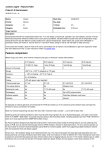
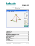
Radiocrafts
Embedded Wireless Solutions
RC2300DK/RC2301DK
RC2300DK/RC2301DK Demonstration Kit User Manual
Table of contents
TABLE OF CONTENTS ..........................................................................................................1
INTRODUCTION .....................................................................................................................2
DEMONSTRATION BOARD ...................................................................................................3
POWER SUPPLY SECTION ...................................................................................................4
RS-232 INTERFACE ...............................................................................................................5
CONNECTORS .......................................................................................................................6
PUSH BUTTONS.....................................................................................................................6
LEDS .......................................................................................................................................6
ACCELEROMETER ................................................................................................................6
POTENTIOMETER ..................................................................................................................7
LIGHT SENSOR ......................................................................................................................7
DEBUG AND PROGRAMMING INTERFACE .........................................................................8
I/O MAPPING ........................................................................................................................10
USING THE DEMONSTRATION KIT ....................................................................................11
SW IMPLEMENTATION ........................................................................................................11
CIRCUIT DIAGRAM ..............................................................................................................12
BILL OF MATERIALS ...........................................................................................................13
PCB LAYOUT........................................................................................................................14
TROUBLESHOOTING...........................................................................................................16
DOCUMENT REVISION HISTORY .......................................................................................17
DISCLAIMER.........................................................................................................................17
TRADEMARKS .....................................................................................................................17
LIFE SUPPORT POLICY.......................................................................................................17
CONTACT INFORMATION ...................................................................................................17
©2007 Radiocrafts AS
RC2300DK/RC2301DK Demonstration Kit User Manual (rev. 2.0)
Page 1 of 17
Radiocrafts
Embedded Wireless Solutions
RC2300DK/RC2301DK
Introduction
The RC2300/RC2301 Zigbee-ready modules provide a very compact solution for a wide
range of wireless network applications. The kit can be used to develop and test proprietary
protocol applications as well as ZigBee-based applications.
The RC2300 kit is normally shipped with an embedded firmware for range testing, while the
RC2301 kit is shipped with a location demo firmware.
The kit can be used for development of a customer’s proprietary protocol, or any Zigbee
network implementation ported to the RC230x hardware platform. In this case the user would
re-flash the modules with his own application, and the program/debug interface could be used
for debugging also.
The RC2300DK Demonstration Kit is designed to make it easy for the user to evaluate the
module and/or develop an application very quickly. With the RC2300DK Demonstration Kit
you can:
• evaluate the RF performance of the modules
• develop your own application interfacing the modules
• build a prototype of your application
This User Manual describes how to interface the Demonstration Kit and provide detailed
documentation for the Demonstration Board and its onboard resources.
Your RC2300DK Demonstration Kit should contain the following items:
Kit contents RC2300DK
Item
Demonstration Board (RC2300DB)
RS232 serial cable (1:1)
AC/DC battery eliminator 6VDC
Number of articles
2
2
2
Kit contents RC2301DK
Item
Demonstration Board (RC2301DB)
RS232 serial cable (1:1)
AC/DC battery eliminator 6VDC
Quarter wave whip antenna
Snap on battery clip (for blind node)
Number of articles
8
1
7
8
1
©2007 Radiocrafts AS
RC2300DK/RC2301DK Demonstration Kit User Manual (rev. 2.0)
Page 2 of 17
Radiocrafts
Embedded Wireless Solutions
RC2300DK/RC2301DK
Demonstration Board
The Demonstration Kit includes two Demonstration Boards. The Demonstration Boards
contain the RC230x module and associated support circuits. The board provides an a serial
port driver circuit for RS232 and the 9-pin D-Sub connector, DEBUG interface for
programming and debugging, access to all digital and analogue I/O, push-buttons, LEDs, a
potentiometer, a light sensor and an accelerometer as well as a voltage regulator.
Configuration jumpers and connectors make it easy to interface the RC230x with various test
equipment or the host used in an application. Not all components are needed in an actual
application. Please see the datasheet for a typical application circuit.
DC jack
Digital I/O
connector
Supply voltage
terminal block
RESET
LEDs
RS232
D-Sub
RC2300AT
Antenna
IO jumpers
Accelerometer
DEBUG
VCC jumper
Push buttons
Light
sensor
Potentiometer
Figure 1: RC230xDB Demonstration Board
The SMA connector layout pattern is not used on this board (and is not connected to the
module antenna output) as the module contains a chip antenna.
Typical range measured between two boards in line-of-sight is 110 meters when the chip
antennas are oriented vertically (or parallel). Indoors a range of 10-30 can be expected,
depending on the materials in walls and floors.
©2007 Radiocrafts AS
RC2300DK/RC2301DK Demonstration Kit User Manual (rev. 2.0)
Page 3 of 17
Radiocrafts
Embedded Wireless Solutions
RC2300DK/RC2301DK
Power supply section
The board contains a voltage regulator. You can choose between applying a 4-10V
unregulated supply voltage at the DC jack (like the battery eliminator included in the kit), or
the screw terminal where a battery pack or some other supply can be connected. The onboard regulator drops the voltage to 3.0V. A green LED will light up the board is connected to
a power source.
Input supply voltage range is 4 – 10 V. A series diode protects the circuit against wrong
polarity.
The current supply to the module is through the jumper at P13, pin 3 and 4. An ampere meter
can be connected here in order to measure the DC current drawn by the module. Remove the
jumper and replace by an ampere meter in order to measure the current. The location of P13,
pin 3 and 4, are shown in the figure below.
P13, pin 3 and 4.
Connect a jumper or an
ampere meter here
Figure 2. Module current consumption measurement
Note: To ensure proper Power-On Reset (POR) the wall socket end of the AC/DC battery
eliminator should be inserted first, and then the DC-jack into the board. If the VCC power-on
rise-time specification is not met, the board may need the RESET to be activated to ensure
correct start-up.
©2007 Radiocrafts AS
RC2300DK/RC2301DK Demonstration Kit User Manual (rev. 2.0)
Page 4 of 17
Radiocrafts
Embedded Wireless Solutions
RC2300DK/RC2301DK
RS-232 interface
The Demonstration Board provides an RS232 driver circuit. The serial port is configured as a
data modem and a 1:1 cable should be used to connect the board to the PC. The RTS/CTS
handshaking pair is also provided, so that hardware handshaking may be used on this port.
The serial port (RXD and TXD) and handshaking signals can be HW enabled by doing the
following hardware changes:
•
•
Insert jumpers at P13 to connect RXD and TXD to the RS232 driver
Insert jumpers at P13 to connect CTS and RTS to the RS232 driver if hardware
handshake is to be used
P13 is used to set jumpers to connect the module UART interface to the RS232 PHY driver.
Normally the jumpers connecting RXD and TXD are installed, and provide UART
communication with a PC without handshaking. With the jumpers removed the modules RXD
and TXD can easily be connected to a host using logic levels, for instance a microcontroller or
external development board. The table below shows the pinout and signals at P13.
There are two LEDs indicating traffic activity on the UART. A green LED is connected to the
RXD line, and a red LED at the TXD line.
Pin no.
Signal
1
3
2
4
GND
VCC
5
7
9
11
13
6
8
10
12
14
RXD
TXD
CTS
RTS
GND
Note
Ground
Jumper installed from factory. Can be used for
current measurement
Jumper installed from factory
Jumper installed from factory
Install jumper when using hardware handshake
Install jumper when using hardware handshake
Ground
Connect jumpers here
for TXD and RXD
Connect jumpers here
for hardware handshake
(CTS, RTS)
Figure 3. RS232 driver interface (Photo to be updated!)
©2007 Radiocrafts AS
RC2300DK/RC2301DK Demonstration Kit User Manual (rev. 2.0)
Page 5 of 17
Radiocrafts
Embedded Wireless Solutions
RC2300DK/RC2301DK
Connectors
The Demonstration Board is furnished with many connectors for easy access to all module
signals.
P5 bring out supply voltage, the DEBUG interface, a spare digital data I/O signal (Port 2) and
the RESET line.
P6 brings out digital and analogue I/O (Port 0). A 2.54 mm pitch pin-row can be mounted at
P6 if convenient.
P7 brings out digital I/O (Port 1) and the 32 kHz oscillator clock pins. A 2.54 mm pitch pin-row
can be mounted at P7 if convenient.
P8 is the DEBUG interface (pin compatible with the TI / Chipcon SmartRF04DB DEBUG
connector).
P9 is a connector for jumpers to connect/disconnect the on-board analogue sensors
preventing them loading the pins when not used.
P10 is a connector for jumper to connect VCC from the demonstration board back to the
programmer/EB.
For detailed signal description, please refer to the pinout shown in the data sheet.
Push buttons
The Demonstration Board is furnished with 6 push buttons connected to the following I/O
signals:
Demo Board
marking
S1
S2
S3
S4
S5
S7
RC2300 module pin
P0.1
P0.6
P1.2
P1.3
P2.0
RESET. Pressing this button will
activate the main RESET of the
module
LEDs
The Demonstration Board is furnished with one green power indicator LED, two LEDs
indicating UART activity as described above, and 2 LEDs connected to general I/O signals:
Demo Board
marking
D3
D6
LED color and RC2300 module pin
Green: P1.0
Red: P1.1
Accelerometer
The accelerometer can be used measure movements in 2-axis, it can also be used for tilt
measurement by measuring the earths gravitation. Accelerometer self test can be initiated by
shorting test point T1 to ground. The accelerometer has a 20 ms start-up time after power on.
See the Analog Devices ADXL321 datasheet for details about the accelerometer.
©2007 Radiocrafts AS
RC2300DK/RC2301DK Demonstration Kit User Manual (rev. 2.0)
Page 6 of 17
Radiocrafts
Embedded Wireless Solutions
RC2300DK/RC2301DK
Potentiometer
The potentiometer is connected as a voltage divider between supply voltage and ground.
Turning the knob clock-wise gives maximum voltage.
Light sensor
A light dependent resistor (LDR) measures the light level and gives an analogue signal that
can be measured by the RC230x A/D converter. The light sensor resistance ranges from 5K
(light) to 20M (dark), and is connected a voltage divider together with a 200k Ohm resistor to
the supply voltage. See the Silonex NSL-19M51 datasheet for details about the LDR.
©2007 Radiocrafts AS
RC2300DK/RC2301DK Demonstration Kit User Manual (rev. 2.0)
Page 7 of 17
Radiocrafts
Embedded Wireless Solutions
RC2300DK/RC2301DK
Debug and programming interface
The Demonstration Board provides a DEBUG interface used to program firmware into the onboard module and for debugging the code. The DEBUG interface is compatible with the
DEBUG interface at the Texas Instruments / Chipcon SmartRF04EB board. This board and its
associated software are available from TI / Chipcon. The table below shows the P8 SOC
debug connector pin-out. See figure Figure 4.
Another option for programming is a third party programmer as FlashPro-CC from Elprotronic,
as shown in Figure 5
Debug interface pin
1
2
3
4
5
6
7
8
9
10
Function
GND
VCC (Insert jumper at P10 to connect
VCC from target to the
programmer/EB)
Debug Clock (DC)
Debug Data (DD)
CSn (optional)
SCL (optional)
RESET_N
MOSI (optional)
NC (not connected)
MISO (optional)
Below is shown how to connect the RC2300DB to the SmartRF04EB.
©2007 Radiocrafts AS
RC2300DK/RC2301DK Demonstration Kit User Manual (rev. 2.0)
Page 8 of 17
Radiocrafts
Embedded Wireless Solutions
RC2300DK/RC2301DK
Figure 4. Programming interface connection from SmartRF04EB (Texas Instruments)
Figure 5. Programming interface connection from FlashPro-CC
©2007 Radiocrafts AS
RC2300DK/RC2301DK Demonstration Kit User Manual (rev. 2.0)
Page 9 of 17
Radiocrafts
Embedded Wireless Solutions
RC2300DK/RC2301DK
I/O mapping
The following table is a summary of the I/O mapping and their connection to the on-board
resources. In the same table the pin usage for the TI/Chipcon CC2430DB is shown for
reference.
I/O port
P0.0
RC2300
pin
8
P0.1
P0.2
P0.3
P0.4
9
10
11
12
P0.5
13
P0.6
P0.7
14
15
P1.0
P1.1
P1.2
29
28
27
RC230xDB
Demo Board
Light dependent resistor (through
jumper)
S1 push button
I2C_SDA
I2C_SDL
Accelerometer x-axis (through
jumper)
Accelerometer y-axis (through
jumper)
S2 push button
Potentiometer analogue input
(through jumper)
D3, Green LED
D6, Red LED
S3 push button
P1.3
P1.4
P1.5
P1.6
P1.7
P2.0
26
25
24
23
22
5
S4 push button
CTS
RTS
TXD
RXD
S5 push button
P2.1
P2.2
RESET
4
3
6
Debug data
Debug Clock
S7 push button, RESET. Pressing
this button will activate the main
RESET of the module
©2007 Radiocrafts AS
CC2430DB
TI/Chipcon demo board
Light dependent resistor
Push button
EEPROM SDA
EEPROM SCL
Accelerometer x-axis
Accelerometer y-axis
Joystick analogue signal
Potentiometer analogue
input
Green LED
Red LED
Voltage control for I/O
modules
General purpose I/O
CTS
RTS
TXD
RXD
Joystick push interrupt
active high
Debug data
Debug Clock
RESET
RC2300DK/RC2301DK Demonstration Kit User Manual (rev. 2.0)
Page 10 of 17
Radiocrafts
Embedded Wireless Solutions
RC2300DK/RC2301DK
Using the Demonstration Kit
The Demonstration Kit is useful for providing hands-on experience with the RC2300 for both
software and hardware developers. The Data Sheet for the module provides detailed
information on the internal resources and available I/Os of the modules.
Important: The use of radio transceivers is regulated by international and national rules.
Radiocrafts’ modules meet the regulations in EU and US/Canada for different frequency
variants. Make sure the local regulative are according to these rules. Your local
telecommunication authorities can provide more information on use of un-licensed radio
transmitter in your country.
SW implementation
For implementing your application IAR Embedded Workbench is recommended. En example
IAR project for the embedded microcontroller can be downloaded from TI/Chipcon homepage.
User guides for how to integrate module programming into IAR is also available there.
The Z-stack from TI/Chipcon currently (rev 1.4.2) supports only revision 7.20H of the IAR
Embedded Workbench and not the newest (7.21 and 7.30). Check TI’s website
http://focus.ti.com/docs/toolsw/folders/print/z-stack.html for latest update on this.
A flyer for IAR Embedded Workbench is included in the kit. More info on IAR can be found on
IAR homepage (www.iar.com).
©2007 Radiocrafts AS
RC2300DK/RC2301DK Demonstration Kit User Manual (rev. 2.0)
Page 11 of 17
Radiocrafts
Embedded Wireless Solutions
RC2300DK/RC2301DK
Circuit Diagram
The circuit diagram is shown below. A full resolution schematic is found in
RC2300DB_1_0.zip (available from Radiocrafts’ website).
©2007 Radiocrafts AS
RC2300DK/RC2301DK Demonstration Kit User Manual (rev. 2.0)
Page 12 of 17
Radiocrafts
Embedded Wireless Solutions
RC2300DK/RC2301DK
Bill of materials
Reference
C1
C2
C3-7;C10
C8-9
D1
D2-4
D6-7
M1
P1
P2
P3
Quantity
1
1
6
2
1
3
2
1
1
1
1
P4
P8
P9
P10
P13
1
1
1
1
1
SMA
CON_2X5_TH_MALE
CON_2X4_TH_MALE
CON_2_TH_MALE
CON_2X10_TH_MALE
R1
R2
R7-9;R1112
R3-4,R10
R5; R13
RT1
S1-5, S7
U1
U2
U3
1
1
NSL-19M51
R_200K_0603_F
Description
Capacitor, 0603
Capacitor, tantal
Capacitor, 0603
Capacitor, 0603
Diode, Si
LED, green, SMD
LED, red, SMD
RF Module
D-Sub, 9 pin, female
2 pin terminal, screw
DC jack, 2.5mm center pin
SMA connector, straight
Not populated
Connector 10 pins, pin header
Connector 8 pins, pin header
Connector 2 pins, pin header
Connector 20 pins, pin header
Light Sensitive Resistor, 5k20M Ohm
Resistor, 0603
5
3
2
1
7
1
1
1
R_100K_0603_G
R_150_0603_G
R_1K0_0603_J
72PTR10K
PUSH_BUTTON
MAX3232
LP2980-3.0V
ADXL321
Resistor, 0603
Resistor, 0603
Resistor, 0603
Trimming pot, 10K, knob
Push button, SMD
RS-232 Transceiver, SO-16
3.0V low drop-out regulator
Dual-axis Accelerometer, QFN
©2007 Radiocrafts AS
Part number
C_2U2_0603_X5R_K_10
C_3U3_TAN_B
C_100N_0603_X7R_K_50
C_10N_0603_X7R_K_50
BAT254
LED_CL150GCD
LED_CL150URCD
RC2300AT
DSUB_9F
SCREW_TERM_2
DC_JACK_2.5
RC2300DK/RC2301DK Demonstration Kit User Manual (rev. 2.0)
Page 13 of 17
Radiocrafts
Embedded Wireless Solutions
RC2300DK/RC2301DK
PCB layout
The PCB is a simple 2-layer board where the bottom layer is used as ground plane. The
laminate used is standard FR-4 board material. The PCB is 1.6mm thick. Full resolution
layout and assembly drawing are found in RC2300DB_1_0.zip.
Figure 6. RC2300DB PCB layout, top layer (1)
Figure 7. RC2300DB PCB layout, bottom layer (2)
©2007 Radiocrafts AS
RC2300DK/RC2301DK Demonstration Kit User Manual (rev. 2.0)
Page 14 of 17
Radiocrafts
Embedded Wireless Solutions
RC2300DK/RC2301DK
Figure 8. RC2300DB PCB component placement, top side
©2007 Radiocrafts AS
RC2300DK/RC2301DK Demonstration Kit User Manual (rev. 2.0)
Page 15 of 17
Radiocrafts
Embedded Wireless Solutions
RC2300DK/RC2301DK
Troubleshooting
It doesn’t work
• First, measure the supply voltage at P13, pin 3. Should be 3.0V.
•
Make sure that a jumper is installed or an ampere meter is connected between pin 3
and 4 on P13.
•
Is the supply voltage correctly polarized? If not, the protection diode will prevent any
current from flowing. + and – are indicated on the PCB, on the DC jack, the tip is +
and the ring is –.
•
Is the battery eliminator plugged into the wall socket?
•
Was the wall socket plugged in first, then the DC-jack to ensure quick rise-time on
VCC? If not the module may have to be reset after power on. Press the RESET
button.
•
Is the wall outlet at the rated voltage printed on the AC/DC battery eliminator (220V or
110V)?
•
Is the module programmed with the proper firmware? If not use the TI / Chipcon
SmartRF04EB DEBUG interface to load the firmware.
I cannot communicate with the RC2300 UART through the serial port
• Make sure that the RXD and TXD jumpers are inserted
•
Make sure that you are using a correctly wired 1:1 cable (as the one provided with the
kit)
•
Make sure the PC (or host) is configured for the correct serial port
•
Make sure the PC serial port settings are correct with respect to baud rate, data bits,
stop bits, parity bits and handshake
©2007 Radiocrafts AS
RC2300DK/RC2301DK Demonstration Kit User Manual (rev. 2.0)
Page 16 of 17
Radiocrafts
Embedded Wireless Solutions
Document Revision History
Document Revision
1.0
2.0
RC2300DK/RC2301DK
Changes
New document
Updated with RC2301DK, and information on programming options
Disclaimer
Radiocrafts AS believes the information contained herein is correct and accurate at the time of this printing. However,
Radiocrafts AS reserves the right to make changes to this product without notice. Radiocrafts AS does not assume
any responsibility for the use of the described product; neither does it convey any license under its patent rights, or
the rights of others. The latest updates are available at the Radiocrafts website or by contacting Radiocrafts directly.
As far as possible, major changes of product specifications and functionality, will be stated in product specific Errata
Notes published at the Radiocrafts website. Customers are encouraged to check regularly for the most recent
updates on products and support tools.
Trademarks
SPPIO is a trademark of Radiocrafts AS. ZigBee is a registered trademark of the ZigBee Alliance.
All other trademarks, registered trademarks and product names are the sole property of their respective owners.
Life Support Policy
This Radiocrafts product is not designed for use in life support appliances, devices, or other systems where
malfunction can reasonably be expected to result in significant personal injury to the user, or as a critical component
in any life support device or system whose failure to perform can be reasonably expected to cause the failure of the
life support device or system, or to affect its safety or effectiveness. Radiocrafts AS customers using or selling these
products for use in such applications do so at their own risk and agree to fully indemnify Radiocrafts AS for any
damages resulting from any improper use or sale.
© 2007, Radiocrafts AS. All rights reserved.
Contact Information
Web site: www.radiocrafts.com
Email: [email protected]
Address:
Radiocrafts AS
Sandakerveien 64
NO-0484 OSLO
NORWAY
Tel: +47 4000 5195
Fax: +47 22 71 29 15
E-mail: [email protected]
©2007 Radiocrafts AS
RC2300DK/RC2301DK Demonstration Kit User Manual (rev. 2.0)
Page 17 of 17