1
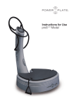
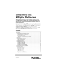
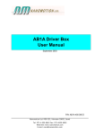
99 Washington Street
Melrose, MA 02176
Phone 781-665-1400
Toll Free 1-800-517-8431
Visit us at www.TestEquipmentDepot.com
Dual Output
DC Power Supply
1415
User Manual
Safety Summary
A WARNING statement calls attention to an operating procedure,
practice, or condition, which, if not followed correctly, could result in
injury or death to personnel.
A CAUTION statement calls attention to an operating procedure,
practice, or condition, which, if not followed correctly, could result in
damage to or destruction of parts or the entire product.
The following safety precautions apply to both operating and
maintenance personnel and must be followed during all phases of
operation, service, and repair of this instrument.
WARNING
Before applying power to this instrument:
• Read and understand the safety and operational information
in this manual.
• Apply all the listed safety precautions.
• Verify that the voltage selector at the line power cord input is
set to the correct line voltage. Operating the instrument at
an incorrect line voltage will void the warranty.
• Make all connections to the instrument before applying
power.
• Do not operate the instrument in ways not specified by this
manual or by Global Specialties
Electrical Power
This instrument is intended to be powered from a CATEGORY II
mains power environment. The mains power should be 120 V RMS
or 240 V RMS. Use only the power cord supplied with the instrument
and ensure it is appropriate for your country of use.
Ground the Instrument
WARNING
To minimize shock hazard, the instrument chassis and cabinet must
be connected to an electrical safety ground. This instrument is
grounded through the ground conductor of the supplied, threeconductor AC line power cable. The power cable must be plugged
into an approved three-conductor electrical outlet. The power jack
and mating plug of the power cable meet IEC safety standards.
WARNING
Do not alter or defeat the ground connection. Without the safety
ground connection, all accessible conductive parts (including control
knobs) may provide an electric shock. Failure to use a properlygrounded approved outlet and the recommended three-conductor
AC line power cable may result in injury or death.
WARNING
Unless otherwise stated, a ground connection on the instrument's
front or rear panel is for a reference of potential only and is not to be
used as a safety ground.
Do not operate in an explosive or flammable atmosphere
WARNING
Do not operate the instrument in the presence of flammable gases
or vapors, fumes, or finely divided particulates.
Use only in office-type indoor setting
WARNING
The instrument is designed to be used in office-type indoor
environments. Do not operate the instrument:
• In the presence of noxious, corrosive, or flammable fumes,
gases, vapors, chemicals, or finely-divided particulates.
• In relative humidity conditions outside the instrument's
specifications.
• In environments where there is a danger of any liquid being
spilled on the instrument.
• In air temperatures exceeding the specified operating
temperatures.
• In atmospheric pressures outside the specified altitude limits
or where the surrounding gas is not air.
• In environments with restricted cooling air flow, even if the
air temperatures are within specifications.
• In direct sunlight.
CAUTION
This instrument is intended to be used in an indoor pollution degree
2 environment. The operating temperature range is 0 °C to 40 °C
and the operating humidity range is up to 80% relative humidity with
no condensation allowed. Measurements made by this instrument
may be outside specifications if the instrument is used in non-officetype environments. Such environments may include rapid
temperature or humidity changes, sunlight, vibration and/or
mechanical shocks, acoustic noise, electrical noise, strong electric
fields, or strong magnetic fields.
Do not operate instrument if damaged
If the instrument is damaged, appears to be damaged, or if any
liquid, chemical, or other material gets on or inside the instrument,
remove the instrument's power cord, remove the instrument from
service, label it as not to be operated, and return the instrument to
Global Specialties for repair. Notify Global Specialties of the nature
of any contamination of the instrument.
Clean the instrument only as instructed
Do not clean the instrument, its switches, or its terminals with
contact cleaners, abrasives, lubricants, solvents, acids/bases, or
other such chemicals. Clean the instrument only with a clean dry
lint-free cloth or as instructed in this manual.
Not for critical applications
WARNING
This instrument is not authorized for use in contact with the human
body or for use as a component in a life-support device or system.
Do not touch live circuits
WARNING
Instrument covers must not be removed by operating personnel.
Component replacement and internal adjustments must be made by
qualified service-trained maintenance personnel who are aware of
the hazards involved when the instrument's covers and shields are
removed. Under certain conditions, even with the power cord
removed, dangerous voltages may exist when the covers are
removed. To avoid injuries, always disconnect the power cord from
the instrument, disconnect all other connections (for example, test
leads, computer interface cables, etc.), discharge all circuits, and
verify there are no hazardous voltages present on any conductors
by measurements with a properly-operating voltage-sensing device
before touching any internal parts. Verify the voltage-sensing device
is working properly before and after making the measurements by
testing with known-operating voltage sources and test for both DC
and AC voltages. Do not attempt any service or adjustment unless
another person capable of rendering first aid and resuscitation is
present. Do not insert any object into an instrument's ventilation
openings or other openings.
WARNING
Hazardous voltages may be present in unexpected locations in
circuitry being tested when a fault condition in the circuit exists.
Fuse replacement
WARNING
Fuse replacement must be done by qualified service-trained
maintenance personnel who are aware of the instrument's fuse
requirements and safe replacement procedures. Disconnect the
instrument from the power line before replacing fuses. Replace
fuses only with new fuses of the fuse types, voltage ratings, and
current ratings specified in this manual or on the back of the
instrument. Failure to do so may damage the instrument, lead to a
safety hazard, or cause a fire. Failure to use the specified fuses will
void the warranty.
Servicing
CAUTION
Do not substitute parts that are not approved by Global Specialties
or modify this instrument. Return the instrument to Global
Specialties for service and repair to ensure that safety and
performance features are maintained.
Cooling fans
CAUTION
This instrument contains one or more cooling fans. For continued
safe operation of the instrument, the air inlet and exhaust openings
for these fans must not be blocked nor must accumulated dust or
other debris be allowed to reduce air flow. Maintain at least 25 mm
clearance around the sides of the instrument that contain air inlet
and exhaust ports. If mounted in a rack, position power devices in
the rack above the instrument to minimize instrument heating while
rack mounted. Do not continue to operate the instrument if you
cannot verify the fan is operating (note some fans may have
intermittent duty cycles). Do not insert any object into the fan's inlet
or outlet.
Use correctly sized wires
WARNING
To connect a load to the power supply, use a wire diameter large
enough to handle the maximum continuous output short-circuit
current of the power supply without the wire overheating.
For continued safe use of the instrument
•
•
•
•
•
Do not place heavy objects on the instrument.
Do not obstruct cooling air flow to the instrument.
Do not place a hot soldering iron on the instrument.
Do not pull the instrument with the power cord, connected
probe, or connected test lead.
Do not move the instrument when a probe is connected.
Compliance Statements
Disposal of Old Electrical & Electronic Equipment
(Applicable in the European Union and other
European countries with separate collection
systems). This product is subject to Directive
2012/19/EU of the European Parliament and the
Council of the European Union on waste electrical
and electronic equipment (WEEE), and in
jurisdictions adopting that Directive, is marked as
being put on the market after August 13, 2005, and should not be
disposed of as unsorted municipal waste. Please utilize your local
WEEE collection facilities in the disposition of this product and
otherwise observe all applicable requirements.
The 1415 is CE compliant.
Table of Contents
1 General Information .................................................................. 8
1.1
1.2
1.3
1.4
1.5
1.6
Product Overview
Features
Constant Voltage (CV) /Constant Current (CC) Mode
Package Contents
Front Panel Overview
Rear Panel
8
8
8
9
10
11
2 Getting Started ......................................................................... 12
2.1 Input Power and Fuse Requirements
12
2.2 Fuse Requirements
12
2.3 Line Voltage Selection
13
2.3.1 Check and/or Change Fuse ....................................................... 13
2.3.2 Check and/or Change Line Voltage Switch ............................... 13
2.4 Ventilation
14
3 Operating the Power Supply .................................................. 14
3.1 Setting the Variable Output Voltage & Current
14
3.2 System Configuration
15
3.2.3 Multiple Units in Series .............................................................. 15
3.2.4 Multiple Units in Parallel ............................................................ 16
3.3 Fixed 5V/3A Output
16
4 Specifications .......................................................................... 17
5 Maintenance ............................................................................. 18
5.1 Preventative Steps
5.2 When the Unit is Not Turning On
5.3 Fuse Replacement
18
18
18
6 Service and Warranty Information ......................................... 19
6.1 Limited One-Year Warranty
6.2 Calibration and Repair
19
19
1
General Information
1.1 Product Overview
Global Specialties Model 1415 Dual Output DC Power Supply
provides one variable output (0 – 30 V / 0 – 3 A) and one fixed
output (5 V / 3 A). The variable output features both constant current
& constant voltage modes with automatic crossover between the
two. Each mode has its own LED indicator. Connect multiple units in
series or in parallel for greater voltage or current output.
1.2 Features
•
•
•
•
•
•
•
•
•
•
One variable output: 0-30 V / 0-3 A
One fixed output: 5 V / 3 A
Separate 3-digit displays for voltage and current on the
variable output
Individual control of voltage and current for the variable
output
CV (constant voltage) / CC (constant current) mode
operation
LED indication for CV / CC mode
Overload indication LED for the fixed output
Operate multiple units in series or in parallel for greater
output
Power On/Off switch on front panel
Input voltage selection on rear side (120/240 VAC)
1.3 Constant Voltage (CV) /Constant Current (CC) Mode
The working characteristic of this power supply is called a constant
voltage/constant current automatic crossover type. This permits
continuous transition from constant current to constant voltage
modes in response to the load change. The intersection of constant
voltage and constant current modes is called the crossover point.
Figure 1 shows the relationship between this crossover point and
the load.
For example, if the load is such that the power supply is operating in
the constant voltage mode, a regulated output voltage is provided.
The output voltage remains
constant as the load increases,
up until the point where the
preset current limit is reached. At
that point, the output current
becomes constant and the output
voltage drops in proportion to
further increases in load.
Figure 1: CC, CV Characteristics
The crossover point is indicated
by the front panel LED indicators.
The crossover point is reached when the CV indicator goes off and
the CC indicator comes on. Similarly, crossover from the constant
current to the constant voltage mode automatically occurs from a
decrease in load.
1.4 Package Contents
Please inspect the instrument mechanically and electrically upon
receiving it. Unpack all items from the shipping carton, and check for
any obvious signs of physical damage that may have occurred
during transportation. Report any damage to the shipping agent
immediately. Save the original packing carton for possible future
reshipment.
The 1415 power supply is shipped with the following contents:
•
•
•
•
1415 Power Supply
AC Power Cord
User Manual
Banana Plug to Alligator Clip Lead Wires (Black & Red)
1.5 Front Panel Overview
Figure 2: Front Panel
1.
2.
3.
4.
5.
6.
7.
8.
9.
10.
11.
12.
13.
Power switch
Negative output terminal of the fixed 5V/3A output (black)
Positive output terminal of the fixed 5V/3A output (red)
Overload indicator LED for the fixed 5V/3A output
Negative output terminal of the variable output
Ground terminal of the variable output
Positive output terminal of the variable output
CC mode LED to indicate constant current
CV mode LED to indicate constant voltage
Variable output voltage adjustment knob
Variable output current adjustment knob
Variable voltage indicator display (3-digit green 0.52" LED)
Variable current indicator display (3-digit red 0.52" LED)
Figure 3: Front Panel Diagram
1.6 Rear Panel
A.
B.
C.
D.
Heat sink: Heat dissipation for power transistor
Ventilation Fan: 8" 24 VDC fan
Power input socket
Fuse holder and input voltage selector: The selected input
voltage is set to the voltage shown near the ▽ mark which
points to “E.”
E. The input power voltage indicator: The ▽ mark points to the
set input line voltage
Figure 4: Rear Panel
2
Getting Started
2.1 Input Power and Fuse Requirements
The supply has a selectable AC input that accepts line voltage input
within:
•
•
Voltage: 115 V or 230 V (±10%)
Frequency: 47 Hz – 63 Hz
Before connecting to an AC outlet or external power source, be sure
that the power switch is in the OFF position and verify that the AC
power cord, including the extension line, is compatible with the rated
voltage/current and that there is sufficient circuit capacity for the
power supply. Once verified, connect the cable firmly.
WARNING
The included AC power cord is safety certified for this instrument
operating in rated range. To change a cable or add an extension
cable, be sure that it can meet the required power ratings for this
instrument. Any misuse with wrong or unsafe cables will void the
warranty.
WARNING
The power cord provides a chassis ground through a third
conductor. Verify that your power outlet is of the three-conductor
type with the correct pin connected to earth ground.
2.2 Fuse Requirements
An AC input fuse is necessary when powering the instrument. The
below table shows the fuse required for all models operating with
either 120 VAC or 240 VAC input.
Selector
Line Voltage
Fuse
120 V
240 V
114 – 126 V, 50/60 Hz
228 – 252 V, 50/60 Hz
3.0 A, 250 V
1.5 A, 250 V
2.3 Line Voltage Selection
The power supplies can be selected to operate with 110 V input or
220 V input. To ensure that your instrument is properly configured to
operate at the desired AC line voltage, please follow the steps
below.
WARNING
For safety, no power should be applied to the instrument while
changing line voltage operation. Disconnect all cables connected to
the instrument before proceeding.
2.3.1 Check and/or Change Fuse
•
•
•
Locate the fuse box next to the AC input connector in the
rear panel (see Figure 4).
With a small flat blade screwdriver, insert into the fuse box
slit to pull and slide out the fuse box as indicated below.
Check and replace fuse (if necessary) for the desired line
voltage operation (see section 2.2).
2.3.2 Check and/or Change Line Voltage Switch
The input power voltage indicator is a black arrow ▽ on the rear
panel near the AC input connector. See Figure 4, “E”. The fuse
holder (Figure 4, “D”) has a both a smaller white arrow ▽ (120 V)
and a smaller black arrow (240 V) on it. The fuse holder should be
rotated so that the fuse holder arrow of the appropriate voltage is
pointing to the larger black input power voltage indicator arrow. See
Figures 5 & 6 below.
Figure 5: 120 V Setup
Figure 6: 240 V Setup
CAUTION
Do not connect power to the instrument until the line voltage
selection is setup correctly. Applying an incorrect line voltage or
configuring the line voltage selection improperly may damage the
instrument and void all warranty.
2.4 Ventilation
CAUTION
Also make sure the ventilation holes are not blocked. Ensure the
ventilation fan is working well (it should turn on at power-on). Do not
load the output if fan is not working otherwise it may cause
overheating.
3
Operating the Power Supply
3.1 Setting the Variable Output Voltage & Current
1.
2.
3.
4.
5.
6.
7.
As per load requirement, calculate the voltage and
maximum current limit to be set on output. Note: V=IR
Disconnect the load from output terminals.
For current limit adjustment, turn the current adjustment
knob counter-clockwise to get minimum current output.
Short the circuit between the positive and negative
variable output terminals by the accessory leads.
Vary the current adjustment knob clockwise until the
current displays the required current limit. The CC LED
will be lit while adjusting the current limit. Remove the
accessory lead after current limit adjustment.
The voltage will be displayed and the CV LED will be lit.
Vary the voltage adjustment knob to get the desired
output voltage on the display.
The power supply can automatically operate between constant
voltage and constant current modes, responding quickly to load
changes. When the CC LED (red) lights up, the CV LED (green) will
be off and the voltage display will be inactive.
3.2 System Configuration
Model 1415 can be operated alone or connected to two or more
other units in series to obtain a higher voltage rating (maximum 240
V), or in parallel to obtain a higher current rating (maximum 24 A).
CAUTION: The GND (green) output terminal should not be used
during series or parallel configuration.
3.2.3 Multiple Units in Series
1.
2.
3.
4.
Set the output current of all connected units equal to or
higher than the desired current and at least one unit
must be set to the desired current.
Connect the negative output terminal of unit 1 to the
positive output terminal of unit 2 (or the next unit).
Repeat for units 2 and 3, and so forth, if needed.
Connect the load between the positive terminal of unit 1
and the negative terminal of the last unit.
The total output voltage will be the sum of the output voltage of each
of the units. The output current will be the equal to the lowest output
current set on these connected units.
CAUTION: The total output voltage must not exceed 240 V.
Figure 7: Series Connection
3.2.4 Multiple Units in Parallel
1.
2.
3.
4.
Adjust all units to the same output voltage.
Make the parallel connection of the positive and the
negative terminals of units 1 and 2.
Repeat for units 2 and 3, and so forth, if needed.
Connect the load between the positive and negative
terminals of the last unit.
The total output current will be the sum of the output current of each
the units. The output voltage will be the voltage set above.
Figure 8: Parallel Connection
CAUTION: The total output current must not exceed 24 A.
3.3 Fixed 5V/3A Output
This is the standard 5V/3A power output provided for supplying the
power to TTL logic circuits. When the load attempts to draw more
than 3 amps from the output, the OVERLOAD indicator will light and
the power supply will fold back, reducing both the output voltage
and current to well below the normal operating limits.
4
Specifications
All specifications apply to the unit after a temperature stabilization time of 15
minutes over an ambient temperature range of 25 °C ± 5 °C.
1415 Dual Output DC Power Supply
Output Parameters
Max Output Power
Number of Outputs
Range
Load Regulation
CC Mode
CV Mode
Fixed 5 V Output
Line Regulation
CC Mode
CV Mode
Fixed 5 V Output
Ripple & Noise
CC Mode
CV Mode
Fixed 5 V Output
Display Accuracy
Voltage & Current
Fixed 5 V Output
General
AC Input
Operating Temperature
Operating Humidity
Dimensions (W x H x D)
Weight
Warranty
Included Accessories
105 W
2 independent & electrically isolated outputs
Variable: 0-30 VDC / 0-3 A
Fixed: 5 V / 3 A
<15 mA
±0.05% + 32 mV
<70 mV
±0.05% + 2 mA
±0.05% + 2 mV
<5 mV
<2.5 mArms
<0.4 mVrms
<1.5 mVrms
0.1% + 2 digits
± 0.25 V
VAC 115/230 ±10%, 50/60 Hz
50 ºF to 104 ºF (10 ºC to 40 ºC)
90% R.H.
9 x 6.7 x 12.2 in (230 x 170 x 310 mm)
13.3 lbs (6.0 kg)
One-year warranty
Power cord, user manual, one pair of test leads
5
Maintenance
5.1 Preventative Steps
Please follow these preventive steps to ensure the proper operation
of your instrument.
•
•
•
•
•
•
•
•
Never place heavy objects on the instrument.
Never place a hot soldering iron on or near the instrument.
Never insert wires, pins, or other metal objects into
ventilation fan.
Never move or pull the instrument with power cord or output
lead. More importantly, never move the instrument when the
power cord or output lead is connected.
Do not obstruct the ventilation holes in the rear panel as this
will increase the internal temperature.
Do not operate the instrument with the cover removed
unless you are a qualified service technician.
Clean and recalibrate the instrument on a regular basis to
keep the instrument looking nice and working well.
Remove any dirt, dust, and grime whenever they become
noticeable on the outside cover using a soft cloth moistened
with a mild cleaning solution.
5.2 When the Unit is Not Turning On
Check if the power ON/OFF switch is turned ON. Check for blown
fuse. If not, then check the power cord. Please make sure that the
power cord is properly connected to the unit. Please also check the
main switch and ensure that the AC supply at your site is the same
as the one mentioned at the rear chassis of the unit.
5.3 Fuse Replacement
If the fuse blows, the LED will not light and the instrument will not
operate. Replace only with the correct value fuse. See sections 2.2
and 2.3.
6
Service and Warranty Information
6.1 Limited One-Year Warranty
Cal Test Electronics warrants this product to be free from defective
material or workmanship for a period of 1 year from the date of
original purchase. Under this warranty, Cal Test Electronics is
limited to repairing the defective device when returned to the
factory, shipping charges prepaid, within the warranty period.
Units returned to Cal Test Electronics that have been subject to
abuse, misuse, damage or accident, or have been connected,
installed or adjusted contrary to the instructions furnished by Cal
Test Electronics, or that have been repaired by unauthorized
persons, will not be covered by this warranty.
Cal Test Electronics reserves the right to discontinue models,
change specifications, price, or design of this device at any time
without notice and without incurring any obligation whatsoever.
The purchaser agrees to assume all liabilities for any damages
and/or bodily injury which may result from the use or misuse of this
device by the purchaser, his employees, or agents.
This warranty is in lieu of all other representations or warranties
expressed or implied and no agent or representative of Cal Test
Electronics is authorized to assume any other obligation in
connection with the sale and purchase of this device.
6.2 Calibration and Repair
If you have a need for any calibration or repair services, please visit
us on the web at: globalspecialties.com. See the “Service” tab. Or
contact us via the “Contact” tab.
Test Equipment Depot - 800.517.8431 - 99 Washington Street Melrose, MA 02176
TestEquipmentDepot.com