1
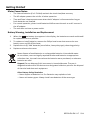
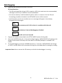
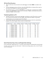
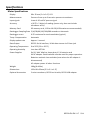
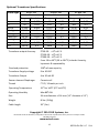
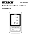
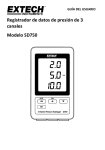
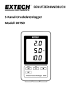
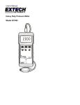
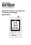
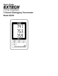
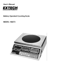
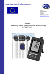
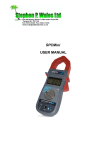
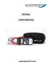
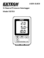
USER GUIDE 3‐Channel Pressure Datalogger Model SD750 Introduction Congratulations on your purchase of the Extech SD750 Pressure Datalogger for use with 2‐wire pressure transducers (optionally available). This meter displays and stores pressure measurement data over time storing the information on a SD card whose data can then be downloaded to a PC. This meter is shipped fully tested and calibrated and, with proper use, will provide years of reliable service. Please visit our website (www.extech.com) to check for the latest version of this User Guide, Product Updates, and Customer Support. Features Monitor Pressure Levels from three separate sources Datalogger date/time stamps and stores readings on an SD card in Excel® format for easy transfer to a PC RS232 serial 16‐bit output stream Selectable data sampling rate: 5, 10, 30, 60, 120, 300, 600 seconds and AUTO Low power consumption, long battery life AC power adaptor (included) For use with 2‐wire pressure transducers (optionally available) 2 SD750-EU-EN V1.7 5/14 Meter Description 1. LCD Display 2. Channel 1 Pressure Reading 3. Channel 2 Pressure Reading 4. Channel 3 Pressure Reading Display 5. Unit of measure for all channels 6. Protective compartment door (side) 7. LOG (ENTER) button 8. SET button 9. ▼ down arrow button 2 1 5 3 4 6 9 10 7 8 10. ▲ (TIME) up arrow button 11. Channel 1 transducer input (4‐20mA) 11 12 13 12. Channel 2 transducer input (4‐20mA) 13. Channel 3 transducer input (4‐20mA) 14 Left side view (behind protective door) 15 14. AC power adaptor jack for supplied adaptor 16 15. Reset button (press if display locks) 16. RS‐232 16‐bit data stream output 17 17. SD memory card socket Note: The battery compartment, tilt stand, and wall mount access holes, not pictured, are located on the rear of the meter. 3 SD750-EU-EN V1.7 5/14 Getting Started Meter Power Notes: o o o o o The internal batteries (6 x 1.5V AAA) maintain the clock time/date accuracy. The AC adaptor powers the unit for all other operation. Time and Date is kept accurate even when the AC adaptor is disconnected as long as fresh batteries are installed. For normal operation, please install batteries AND connect the unit to an AC source via the AC adaptor. The unit does not have a power switch. Battery Warning, Installation and Replacement 1. 2. 3. 4. When the low battery icon appears in the display, the batteries are weak and should be replaced as soon as possible. To replace or install batteries, remove the Philips head screw that secures the rear battery cover and lift off the cover. Replace the six (6) ‘AAA’ batteries (use alkaline, heavy duty type), observing polarity. Replace and secure the cover. Never dispose of used batteries or rechargeable batteries in household waste. As consumers, users are legally required to take used batteries to appropriate collection sites, the retail store where the batteries were purchased, or wherever batteries are sold. Disposal: Do not dispose of this instrument in household waste. The user is obligated to take end‐of‐life devices to a designated collection point for the disposal of electrical and electronic equipment. Other Battery Safety Reminders o Never dispose of batteries in a fire. Batteries may explode or leak. o Never mix battery types. Always install new batteries of the same type. 4 SD750-EU-EN V1.7 5/14 Mounting and Wiring o o o o The SD750 can be placed on a tabletop using the supplied tilt stand, it can be wall mounted using the rear mounting access holes, or it can be laid flat on a desktop or other surface. Up to three 4‐20mADC pressure transducers (two‐wire) can be connected to the bottom of the SD750 as shown in the diagram below. Wiring for 2‐wire transmitters must be configured exactly as shown in the diagram. Only the two terminals on the right for each channel group are to be used. The two terminals on the left for each channel group are unused. Signal positive (S+) and Power positive (V+) are connected to the same terminal as shown in the diagram below. Signal negative (S–) and Power negative (V‐) are connected to the same terminal as shown below. CH1 CH2 CH3 S+ SV+ V- S+ SV+ V- 5 S+ SV+ V- SD750-EU-EN V1.7 5/14 Set Mode Before taking measurements and datalogging, the SD750 must be configured to match the application and transducers in question. The SET mode is used to accomplish the following: o Format a SD memory card o Set the clock date and time o Set the sampling time (datalogging capture rate) o Set the beeper sound ON/OFF o Set the meter to use a decimal (US) or a comma (EU) for readings stored on the SD card o Set the RS232 data output stream ON/OFF o Set CH1, CH2, and CH3 pressure sensor parameters to match the transducer(s) being used o Set the Pressure unit of measure (all channels use the same unit of measure) Note: The datalogger function must be switched OFF before attempting to enter SET mode. SET MODE MENU To enter the SET mode, press and hold the SET button for > 2 seconds, and then release. ‘SET’ will flash quickly on the display and the symbol for the first Menu item Sd F (format SD card) will appear. Follow the steps below to navigate the menu tree and to make and save changes to parameter settings. Note: In the SET mode, if no button is pressed within 5 seconds, the logger will exit the SET mode and return to the standard mode of operation. 1. Sd F: Format the SD card Use the ▲ button to select yES or no. To format (and completely erase) an SD card select ‘yES’ and then press Enter. The formatting process will begin. To skip this step without formatting the card, select ‘no’ and then press SET to advance to the next parameter. 2. dAtE: Set the date and time Use the ▲ or ▼ buttons to adjust the Year/Month/Day/Hour/Minutes/Seconds. Use the Enter button to store and to step through the available fields. When done, Press SET to store the settings and to advance to the next parameter. 3. SP‐t: Set the sample time (datalogging capture rate) Use the ▲ button to select the desired sample rate. The options are: 5, 10, 30, 60, 120, 300, 600 seconds and AUTO. In AUTO, a reading will be stored only when there is a value change of ±10 digits. Press ENTER to store the setting and to advance. 6 SD750-EU-EN V1.7 5/14 4. bEEP: Set the beeper ON or OFF Use the ▲ button to select ON or OFF and then press Enter to store the setting and to advance. 5. dEC: Set the SD card decimal character Use the ▲ button to select USA (for decimal point usage) or Euro (for comma usage) and press ENTER to store the setting and to advance. 6. rS232: Set the RS232 data output stream ON/OFF Use the ▲ button to select ON or OFF and then press ENTER to store the selection and to advance. For streaming of data to a PC via the RS232 Output jack, the optional 407001‐USB kit (RS232 to USB cable and driver CD) along with the 407001 software (available free at the extech website www.extech.com) are required. 7. tyPE CH1: Set Channel 1 Pressure Sensor range The selected range must match the range for a given transducer. Use the ▲ button to select 2, 5, 10, 20, 50, 100, 200, or 400 bar and then press ENTER to store the setting and to advance. 8. tyPE CH2: Set Channel 2 Pressure Sensor type (same procedure as for Channel 1 above) 9. tyPE CH3: Set Channel 3 Pressure Sensor type (same procedure as for Channels 1 and 2) 10. unit: Set the unit of measure for all channels Use the ▲ button to select a unit of measure. All channels share the same unit of measure. 2 The options are BAR, PSI, kg/cm , mm HG, in HG, m H2O, in H20, ATP (atmospheres), and kPa. 11. ESC: Exit the setting mode. Press the SET button to return to normal operation. System RESET If a condition appears where the CPU does not respond to keystrokes or the meter display seems frozen, press the recessed RESET button on the left side of the datalogger behind the protective door to return the meter to a working state (insert a paper clip or similar pointed object to press the RESET button). RS‐232/USB PC Interface For streaming of data to a PC via the RS232 Output jack, the optional 407001‐USB kit (RS232 to USB cable and driver CD) along with the 407001 software (available free at the extech website www.extech.com) are required. 7 SD750-EU-EN V1.7 5/14 Measurements When the meter is properly powered, mounted, configured, and wired to the transducers as described earlier, the meter can begin to be used to accurately display pressure readings. The meter’s LCD shows the Channel 1 input reading on the top, the Channel 2 reading in the center, and the Channel 3 reading on the bottom as shown below. If the x100 indicator is flashing on the display, multiply the displayed reading by a factor of 100 to obtain the correct reading. The unit of measure shown to the right of the Channel 2 reading applies to all channels. Select the unit of measure as described in the SET MODE section. UNITS Channel 1 Channel 2 Channel 3 8 SD750-EU-EN V1.7 5/14 Datalogging 1. Open the left side door and insert an SD card SD Considerations: o The SD card should be at least 1GB in capacity. 4GB is the maximum size recommended, although a card of up to 16GB can be accommodated. o Do not use memory cards formatted by other meters or cameras. Use the SD card formatting procedure included in the SET MODE section of this manual. o If a SD memory card is not installed, an error message will appear in the display. Displayed error messages: CHCArd The memory card is full or there is a problem with the card LobAt The battery is low and datalogging is disabled No CArd The SD card is not inserted 2. Program the meter as described in the SETUP MODE section of this guide. 3. Press the LOGGER button for >2 seconds to begin logging. ‘DATALOGGER’ will appear in the display and the meter will beep each time data is recorded (if beeper is enabled in SET mode). 4. To stop datalogging, press the LOGGER button for > 2 seconds. ‘DATALOGGER’ will change to ‘DATA’ and the meter will count down through the recorded data list reading by reading. Important Note: Never remove the SD memory card while the datalogger is running. 9 SD750-EU-EN V1.7 5/14 SD Card Data Structure 1. 2. 3. When the SD card is first inserted into the datalogger the folder PSB01 is created on the card. The first datalogging session will then create a file PSB 01001.xls. All data will be saved to this file until the number of columns reaches 30,000. After 30,000 columns, a new file (PSB01002.xls) is created. This is repeated every 30,000 columns until PSB01099.xls. At this point a new folder, PSB02 is created and the process is repeated; PSB10 is the final folder. Transferring Data to a PC 1. 2. Remove the memory card from the datalogger and plug it into the SD card slot on the PC. For PCs that do not include an SD card reader, external SD card readers are generally available and can be connected to the PC’s USB jack. Launch Excel® and open the data file on the memory card from within the spreadsheet program. The file will appear similar to the one shown below. Quick Check the Time, Date, and Sample Rate Settings Press and Hold the TIME button for > 2 seconds and the display will automatically cycle through the date, time and sample rate information. To edit these settings please refer to the SET mode section of this guide. 10 SD750-EU-EN V1.7 5/14 Specifications Meter Specifications Display 60 x 50 mm (2.4 x 2.0”) LCD Measurements Pressure from up to 3 two‐wire pressure transducers Input signals Linear 4‐20 mA DC process signal Accuracy ± (0.5% + 2 digits) of reading (meter only, does not include transducer error) Memory Card SD memory card, 1 GB to 16 GB (4 GB maximum recommended) Datalogger Sampling Rate 5/10/30/60/120/300/600 seconds or Automatic Datalogger errors 0.1% maximum for total saved data (typical) Temp. Compensation Automatic Display update rate Approx. 1 second Data Output RS 232 Serial Interface; 16‐bit data stream via 3.5mm jack Operating Temperature 0 to 50°C (32 to 122°F) Operating Humidity Less than 85% RH Power Supplies Six (6) ‘AAA’ Alkaline, heavy duty 1.5 V batteries and 9V AC adaptor. Both methods must be used for proper operation. Batteries maintain time and date (even when the AC adaptor is disconnected) AC adaptor power all other functions Weight 199 g (0.44 lbs.) Dimensions 132 x 80 x 32mm (5.2 x 3.1 x 1.3”) Optional Accessories 2‐wire transducers, RS232 serial cable, RS232 USB adaptor 11 SD750-EU-EN V1.7 5/14 Optional Transducer Specifications Sensor type PT30 ‐ SD Max. Range Resolution bar 2 0.002 Psi 30 0.02 Kg/cm2 2.040 0.002 mm Hg 1500 2 inch Hg 59.05 0.05 meter H20 20.40 0.02 inch H20 802 1 Atmosphere 1.974 0.002 kPA 200.0 0.2 PT150 ‐ SD Max. Range Resolution 10 0.01 150 0.2 10.19 0.01 7500 10 295.2 0.2 101.9 0.1 4010 5 9.87 0.01 1000 1 PT300 ‐ SD Max. Range Resolution 20 0.02 300 0.2 20.40 0.02 15000 20 590.5 0.5 204.0 0.2 8020 10 19.74 0.02 2000 2 Transducer output Accuracy PT30‐SD: ± 1% of F.S. PT150‐SD: ± 1% of F.S. PT300‐SD: ± 1% of F.S. From 10 to 40oC (50 to 104oF) includes linearity, hysteresis & repeatability Overload protection 150% of max capacity Transducer Supply voltage 9 to 30 VDC Transducer Output 4 to 20 mA DC Sensor element Diaphragm Ceramic cell Thread ¼” PS, 19 teeth per inch Operating Temperature 32oF to 140oF (0oC to 40oC) Operating Humidity Max 80% RH Size 34 mm diameter x 134 mm (1.3” diameter x 5.3”) Weight 8.5oz. (240g) Cable length 39” (1m) Copyright © 2014 FLIR Systems, Inc. Reservados todos los derechos, incluyendo el derecho de reproducción total o parcial en cualquier medio ISO‐9001 Certified www.extech.com 12 SD750-EU-EN V1.7 5/14