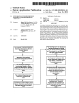
1
CAD Toolkit User Manual LUSAS Version 14.5 : Issue 1 LUSAS Forge House, 66 High Street, Kingston upon Thames, Surrey, KT1 1HN, United Kingdom Tel: +44 (0)20 8541 1999 Fax +44 (0)20 8549 9399 Email: [email protected] http://www.lusas.com Distributors Worldwide Copyright ©1982-2010 LUSAS All Rights Reserved. Table of Contents Table of Contents Introduction 1 LUSAS CAD Toolkit .................................................................................................................... 1 Modeller Import and Export 1 DXF Import and Export............................................................................................................... 1 IGES Import ................................................................................................................................. 1 CADA-X Export............................................................................................................................ 1 PATRAN Neutral File Import and Export .................................................................................. 2 PATRAN Interface ....................................................................................................................... 2 FEMView and FAM Export ......................................................................................................... 2 PATRAN Interface 3 Introduction ................................................................................................................................. 3 Installation ................................................................................................................................... 3 PATRAN to LUSAS (PATLUS).................................................................................................... 4 LUSAS to PATRAN (LUSPAT).................................................................................................. 10 Interface Integration with PATRAN ......................................................................................... 14 PATLUS Element Details .......................................................................................................... 19 LUSPAT Results Columns ....................................................................................................... 27 System Parameters .................................................................................................................. 30 FEMView and FAM Interface 33 Introduction ............................................................................................................................... 33 LUSAS to FEMView/FAM ......................................................................................................... 33 FEMView/FAM Stress Types ................................................................................................... 37 i CAD Toolkit User Manual ii Introduction Introduction LUSAS CAD Toolkit This manual covers interfaces to the LUSAS programs involving the use of external pre- and post-processing packages. The following interfaces are provided for use with LUSAS: DXF Import and Export IGES Import and Export LMS CADA-X Export STEP Import and Export STL Import and Export PATRAN Neutral File Import & Export PATRAN Interface (PATLUS, LUSPAT) FEMView and FAM Interface (FVLUSAS) DXF, IGES, LMS CADA-X, STEP, STL and PATRAN Neutral File import/export facilities are provided in LUSAS Modeller. The use of PATRAN, FEMVIEW and FAM interfaces are described in this manual. i CAD Toolkit User Manual 2 Modeller Import and Export Capability Modeller Import and Export Capability DXF Import and Export DXF is a file format initially developed for import and export of drawing data to and from AUTOCAD. Many programs now support the DXF format and it is often used to transfer geometry data between a variety of system. LUSAS Modeller supports both the import and export of DXF data. Full details can be found in the Modeller Reference Manual. IGES Import and Export IGES is an international standard format for the import and export of Geometry data. Many CAD/Modelling systems support the IGES format. LUSAS Modeller supports the import and export of IGES data. Full details can be found in the Modeller Reference Manual. CADA-X Export CADA-X is a format developed by LMS International to transfer data to and from the LMS LINK modal correlation software package. Full details can be found in the Modeller Reference Manual. STEP Import STandard for the Exchange of Product data (STEP) files are imported according to Part 42 of the Geometric and Topological Representation by using the File > Import menu item. When a file is selected the import process may be controlled from the Advanced button by specify the parameters. 1 CAD Toolkit User Manual LUSAS Model geometry cannot currently be exported to a STEP file. STL Files STL files are used by Stereolithography software. They hold information needed to produce 3D models on Stereolithography machines. STL files are imported from the File> Import menu item. When a file is selected the import process may be controlled from the Advanced button by specify the parameters. LUSAS Model geometry may be exported to IGES from the File> Export menu item. PATRAN Neutral File Import and Export The PATRAN Neutral File format was originally developed for the import and export of data to and form PATRAN. As well as the PATRAN interface to the LUSAS Solver, LUSAS Modeller supports the import of PATRAN Geometry (Phase 1) and the export of finite element data (Phase 2). Full details can be found in the Modeller Reference Manual. PATRAN Interface The LUSAS-PATRAN Interface transfers data between LUSAS Solver and PATRAN. PATRAN is used to generate a neutral file which contains all of the information required to generate a valid LUSAS data deck. The conversion of the data is achieved using the program PATLUS. The conversion of results from LUSAS format to PATRAN format is handled by the program LUSPAT. LUSPAT takes a LUSAS restart file and generates PATRAN results files for each load case and results type. FEMView and FAM Export FVLUSAS is the LUSAS Solver to FEMView/FAM export program supported by FEA Ltd. The program reads results from the LUSAS restart file. The LUSAS restart file is named jobname.rst. A restart file is created by LUSAS using the RESTART WRITE or RESTART WRITE BRIEF commands in the data file or using the appropriate OUTPUT option in various analysis control sections in the data file. 2 PATRAN Interface PATRAN Interface Introduction This section describes the LUSAS-PATRAN Interface for the transfer of data between LUSAS Solver and PATRAN. PATRAN is a registered trademark of the MSc Corporation. Installation All software required for your LUSAS to PATRAN interface should be installed automatically with any software update from FEA Ltd. The files required for running the LUSAS to PATRAN interface (listed below) are all supplied on the standard LUSAS Release Kit. The following files will be installed in the $FEADIR directory: patlus patlus.exe luspat luspat.exe Script for running the PATRAN to LUSAS translator. PATRAN to LUSAS translator. Script for running the LUSAS to PATRAN translator. LUSAS to PATRAN translator. The following files will be installed in the $FEADIR/config directory: patlus.str luspat.str Optional start-up file for the PATRAN to LUSAS translator. Optional start-up file for the LUSAS to PATRAN translator. The following files will be installed in a directory called $FEADIR/patran3 and its sub-directories. lusas.db lusas.plb Database template for the LUSAS preference. PCL library for the LUSAS preference. lusas_dis.res_tmpl lusas_nod_els_2d_thermal.res_tmpl Results template file. Results template file. 3 CAD Toolkit User Manual lusas_nod_els_3d_thermal.res_tmpl lusas_nod_els_membrane_stress.res_tmpl lusas_nod_els_plane_strain.res_tmpl lusas_nod_els_plane_stress.res_tmpl lusas_nod_els_shells_stress.res_tmpl lusas_nod_els_solid_axisymmetric.res_tmpl lusas_nod_els_solid_stress.res_tmpl pat3_lusas.ses lusas_pat3.ses Results template file. Results template file. Results template file. Results template file. Results template file. Results template file. Results template file. Forward translator test session file. Reverse translator test session file. If it is required to run PATLUS/LUSAS/LUSPAT from within PATRAN, the library of supplied files will need to be installed as root using the following procedure: Step One Go to the patran3 subdirectory in your main LUSAS release area containing the required integration tools, for example: cd $FEADIR/patran3 Step Two Copy the necessary integration tool files into the $P3_HOME directory and its associated sub-directories res_templates and test_files, by executing the installation script by typing: ./p3install PATRAN to LUSAS (PATLUS) The conversion of PATRAN data to LUSAS data is achieved using the PATRAN neutral file system. PATRAN is used to generate a neutral file which contains all of the information required to generate a valid LUSAS data deck. The conversion of the data is achieved using the program PATLUS. The input to PATLUS is the neutral file filename.def which is then translated to the LUSAS data deck filename.dat. PATLUS is invoked by typing patlus and specifying the root of the filename to be converted: patlus filename Alternatively, PATLUS and LUSAS may be run directly from within PATRAN using the scripts provided and detailed in this manual. The elements and loading types supported are shown on page 19. 4 PATRAN Interface LUSAS Data Deck The LUSAS data deck generated by PATLUS will contain some or all of the following data sections: Problem Title This is read from the PATRAN neutral file. Options OPTIONS 2 117 118 are inserted automatically. Any further options should be input manually. Element Topology The currently available elements are listed on page 19 together with their PATRAN identification and configuration numbers. For 2D models all element normals should be consistent throughout the structure. The PATRAN user should ensure that all element local axes are consistent, throughout the structure, with the (Hyper) Patch local axes. See the notes on beam and joint orientation at the end of this table. Solution Order Automatic Node Coordinates Geometric Properties Geometric Assignments Material Properties This data chapter is inserted automatically. The Sloan optimiser is selected by default. This data chapter is generated automatically. PATLUS will automatically insert additional dummy nodes for the orientation of beams, joints and coordinate frames. This data chapter is inserted automatically. This data chapter is inserted automatically. Isotropic Material Properties are available. Composite properties are not supported and should be input manually. Material Assignments This data chapter is inserted automatically. 5 CAD Toolkit User Manual Slideline Properties Slideline_Surface Definition This data chapter is inserted when slidelines are generated. All slidelines are initially assigned the default properties as defined in the Modeller Reference Manual. This data chapter is inserted when slideline data is generated within PATRAN using pressure loading with reserved data values. Slidelines are assigned by applying pressures. A load case should be used exclusively for slidelines. Method 1 (INTSL3=0) Master slidelines are assigned a loadset-id in the range 1000-1999 and the corresponding slave slideline is assigned a loadset-id in the range 2000 - 2999 by adding 1000 to the master slideline loadset-id. The pressure value is ignored. Method 2 (INTSL3=1) Slidelines are assigned by inserting a code in the element pressure field. The magnitude of the first component of the applied pressure applied within this load case represents a code: pressure = nnnst where: nnn indicates slideline number. The number must be greater than 99). s indicates whether it is a master (1) or a slave (2) slideline. t indicates the slideline contact type. Options are: (1) sliding, (2) Sliding with friction, (3) Tied slidelines, (4) Sliding only with no lift-off. For example, slideline 111 allowing sliding with friction is defined by pressure load datasets of magnitude 11112 (master) and 11122 (slave). Slideline Assignments This data chapter is inserted when slidelines are generated. All slidelines are assigned property set 1. 6 PATRAN Interface Cartesian Sets Transformed Freedoms Constraint Equations Support Nodes This data chapter is inserted automatically. Note. Cartesian and cylindrical sets are supported but spherical sets are not currently supported in LUSAS. This data chapter is inserted automatically. Note. If a CID is assigned to a node in PATRAN the TRANSFORMED FREEDOMS will be used to reflect the transformation in LUSAS. This information is stored in the LUSAS database allowing the user to generate stress and displacement nodal results in either global or transformed directions. This data chapter is inserted automatically when multi-point constraints (MPCs) are specified in PATRAN. This data chapter is inserted automatically. Notes Each PATRAN data file must contain only one support case. Non-standard nodal freedoms are translated in order, for example, a fully restrained semi-loof shell will restrain freedoms 1 to 5, whereas a fully restrained BMS3 will restrain freedoms 1 to 6. 7 CAD Toolkit User Manual Load Case The currently available loading types for each element are listed on page 19. Notes Analysis Control PATRAN does not allow constant body forces to be applied. This data chapter must, therefore, be input manually. When non-standard freedoms are loaded, the loading should be entered in the order the freedoms appear in LUSAS, e.g. the semiloof elements require loof moments M1 and M2. These should be input in positions Mx and My. For prescribed displacement loading the PATRAN constraint set identification number must be used to assign this loading type to the required load case. For field elements the face load data input should be input to PATRAN in the C1 flag direction. Some analysis control options are available within PATRAN. See pages 8 and 16 for more information. 8 PATRAN Interface Element Output Control All element output is suppressed by default. If specific output is required after the LUSAS run has completed this can be obtained using the LUSAS restart facility. For example: RESTART READ 1 LOAD COMBINATION 1 1 OPTION 55 ELEMENT OUTPUT CONTROL 1 10 1 1 1 NODE OUTPUT CONTROL 1 20 1 3 END Node Output Control Restart Write Brief End Only reactions are output by default. Displacements are suppressed. This LUSAS command is output automatically. This LUSAS command is output automatically. Notes on Beam/Joint Orientation in PATRAN There are two ways of orienting line elements in PATRAN: Node Using a node to define the xy-plane. Local Coordinate System Using a local coordinate system to define the local x axis and xy plane. These are used with two different types of elements: Beam elements These have a finite length and hence a node is sufficient to define the beam axes (x is taken as along the beam axis). All LUSAS beams in PATRAN are oriented using a method 1 above, but the node is an optional parameter. The usual rules apply regarding defaults. Joints These are normally zero length, and hence require a local coordinate system to define both the local x axis and the xy plane. All LUSAS Joint 9 CAD Toolkit User Manual elements in PATRAN are oriented using method 2 above, but the local coordinate is an optional parameter. The usual rules apply regarding defaults. Element local axes are displayed from within the Element Properties dialog box. Use the following procedure: 1. Set the Action to Show. All of the element properties defined will be displayed. 2. Choose X-Y Plane Orient. Node for beams (see note 3 below), or Orientation System for joints (see note 4 below). 3. For beams, the following selections are available: Table produces a report table. Marker Plot marks the elements with their orientation node numbers. Scalar Plot produces a fringe plot of orientation node numbers. 4. For joints, the following selections are available: Table produces a report table. Vector Plot marks the elements with a view of the local coordinate used to orient the joint, provided that the elements have been added to the appropriate Group and the Functional Assignments Display setting has been toggled to Display on FEM Only. LUSAS to PATRAN (LUSPAT) The conversion of results from LUSAS format to PATRAN format is handled by the program LUSPAT. LUSPAT takes a LUSAS restart file and generates PATRAN results files for each load case and results type. Since the results are created from the LUSAS restart file this should be first created by inserting RESTART WRITE BRIEF in the LUSAS data set. This line is written automatically by PATLUS. Interactive Use If LUSPAT is to be used in an interactive mode the user will be prompted for the following information. File: The program will initially prompt the user for the input job file. Input the LUSAS filename without the rst extension. Enter model name (<CR>for jobname)_: An optional model name is prompted for which is used to generate the results file names. If omitted the jobname is used. When run in batch mode the model name will default to the jobname. 10 PATRAN Interface Enter RESTART DUMP number required (zero for all dumps)_: The program will prompt for the RESTART DUMP number. For linear and eigenvalue extraction problems, dump number 1 should be specified. For nonlinear or transient problems all the dumps may be translated by specifying zero. Do you require eigen analysis + nonlinear results [N]_: If an eigenvalue analysis has been preceded by a nonlinear analysis the program will inquire whether the eigen analysis plus the nonlinear results are to be output. Enter LOAD CASE/MODE required (zero for all loads)_: For linear or eigen problems the load case/mode number must be input. If a zero is specified all load cases will be translated. If a load case is specified the prompt will be repeated until a carriage return is specified. When more than one load case/mode is specified the results will be combined with the corresponding load factors. Up to 50 load combinations can be processed at any time. Enter FACTOR required For each load case/mode specified a corresponding factor must be input. If all load cases are to be translated a factor of one is used. Enter STRUCTURE TYPE Beam -1 Plane Membrane -2 Space Membrane -3 Plate Flexure -4 Shell -5 Axisymmetric/Plane strain -6 Solid -7 Field 2D -8 Field 3D -9 Field 1D -10 Enter number _: To prevent invalid data being assembled at common nodes, i.e. between beams and shells, the structure type under consideration must be input. If a model contains two or more structure types the translation process should be repeated for each structure type required. If zero is specified auto structure type selection will be used. When several 11 CAD Toolkit User Manual structure types are present the structure type selected will be the first identified in the results file. Enter material number required (zero for all materials)_: Enter the selected material number as defined in the LUSAS material assignments to enable averaging of stresses for that material only. This feature allows selective nodal averaging of different parts of the structure and may be used, for example, to carry out selective nodal averaging of a branched shell. In this case each branch of the shell should be modelled in PATRAN with a different material assignment. Do you require nodal results in transformed directions [N]_: The displacements and stresses may be output in the transformed directions as defined in the LUSAS transformed freedoms data chapter if required. The transformed freedom assignments in LUSAS are controlled by the CID of the nodes in PATRAN. Do you wish to continue [N]_: Further load cases or modes can be processed by continuing. The default answer stops the program. Batch Mode LUSPAT has been designed to be interactive but may be run in batch by setting the system parameter IBATCH=1 in the LUSPAT start-up file luspat.str as described on page 30. The prompts will then take the following default values which may be overridden as indicated: All restart dumps will be translated, unless the system parameter NDUMP is set to the required dump number. All load cases will be translated. Auto structure type selection will be used, unless the system parameter NSTRUT is set to the required structure type number. All material types will be translated together, unless the system parameter NMAT is set to the required material type number. Eigenvector results will not be superimposed on the nonlinear deformation unless the system parameter IEIGNL is specified. Results will be translated in the global coordinate system, unless the system parameter IRSTRF is specified. Full details of supported system parameters are given on page 30. 12 PATRAN Interface File Naming Convention The conversion used for the result file names produced is: model_number.ext where model is the specified model name, number is the LUSAS restart dump number or the LUSAS load case or eigen mode number, and ext is the extension which indicates the file content. The extensions adopted are: name.def model_number.adp model_number.and model_number.ael structure definition nodal displacements (.dsp for binary file) nodal results (.ndl for binary file) element results (.elm for binary file) where: name is the jobname corresponding to the restart file name. For example, jobname for the file test.rst is test. Note. On certain machine types the documented file naming convention is not adhered to due to system limitations. Results File Titles All results file titles are automatically assembled to include the problem title, the selected material number and the structure type. For nonlinear analysis the load increment and arc length load factor are output. For transient analysis the time step and response time are output. For frequency analysis the mode number, eigenvalue, frequency and error norm are output. For buckling analysis the mode number and load factor are output. The titles given in the displacement, nodal results and element results files take the form: TITLE: problem title TITLE1: model_number structure_type results_type material_no TITLE2: analysis data where: problem title is as defined in the LUSAS data file model_number is as defined in the file name, i.e. test_001 structure_type is as selected, i.e. shell 13 CAD Toolkit User Manual results_type material_no analysis data is the description of the results, e.g. TRANSFORMED AVERAGED RESULTS is the material group selected is defined differently for each problem type. Options are: Linear (blank), Frequency (frequency, error norm), Buckling (load factor), Nonlinear (load increment, load factor), Transient (time step number, response time). Interface Integration with PATRAN Introduction LUSAS has been integrated within PATRAN 3 and above using PCL This enables LUSAS to be run directly from within PATRAN using a single command or menu pick. From within PATRAN the user can use the LUSAS defined menus to set LUSAS up to run different analysis types, control solution optimisation, set output file options and set up the results types and files to be read. The integrated program uses the following files (which should be installed in the directory $P3_HOME): lusas.plb lusas.db LUSAS PCL Library of menu functions. LUSAS database template. The LUSAS preference modifies the following main areas of PATRAN: Materials Material properties are entered which generate the equivalent LUSAS MATERIAL PROPERTIES data chapters. Element Library Elements are selected from those available in the LUSAS element library. See page 19. Loads and Boundary Conditions LUSAS-style Loads, Supports and Constraint Equations can be entered. Analysis Forms The analysis dialogs are configured to suit a LUSAS analysis, with options available for controlling the LUSAS solution procedure. Using Interfaces with PATRAN The analysis and post-processing procedure may be controlled fully using the Analysis dialog box within PATRAN. 14 PATRAN Interface PATRAN to LUSAS Data is transferred from PATRAN to LUSAS by setting the Action on the Analysis dialog to Analyze. The following Action settings are available: Run Analysis translates the data and carries out an analysis. Produce Data Deck translates the data to a LUSAS data deck, but no analysis is carried out. The type of analysis to be carried out is selected using the Solution Type dialog. This will generate a file jobname.ctl which is picked up by PATLUS. The default solution type is linear static. The type of frontwidth optimiser to be used during solution is selected using the Optimiser Type dialog. This will generate a file jobname.opt which is picked up by PATLUS. The default optimiser type is Sloan. The amount of output written to the LUSAS text output file is controlled using the Output Requests dialog. This will generate a file jobname.eno which is picked up by PATLUS. The default is for output of reactions at nodes only. This does not affect the results available for viewing in PATRAN which are extracted from the restart file. PATRAN Neutral File jobname .def Options File jobname .eno Solution File jobname .ctl Start-up File jobname .pls Optimiser File jobname .opt PATLUS LUSAS Data jobname .dat LUSAS Restart File jobname .rst Output File jobname .out 15 Log File jobname .log Method = Analyze Analysis Method = Produce Data Deck PATRAN to LUSAS Translation Procedure CAD Toolkit User Manual PATRAN 2 Menu Mode Neutral File jobname .def Start-up File patlus.str Solution File jobname .ctl Options File jobname .opt Optimiser File jobname .opt Scaling File jobname .scl PATLUS LUSAS Data jobname .dat LUSAS Restart File jobname .rst Output File jobname .out Log File jobname .log Analysis Dialog for PATRAN to LUSAS Subordinate dialogs shown right. 16 PATRAN Interface LUSAS to PATRAN Data is transferred from LUSAS to PATRAN by setting the Action options list on the Analysis dialog to Post Process. The Method setting is used as follows: Translate Results LUSPAT will be invoked to generate results files from the LUSAS restart file jobname.rst. Read Results Files it will be assumed that the relevant binary PATRAN results files already exist. Displacements jobname .dsp Nodal Results jobname .ndl Start-up File jobname .lps PATRAN Analysis 17 Element Results jobname .els Method = Read Results Files LUSPAT Method = Translate Results Restart File jobname .rst LUSAS to PATRAN Translation Procedure CAD Toolkit User Manual A ction is set P too stP ro cess for L U S A S to P A TR A N T ra n sla te R esuwill lts ru n L US A S th en read resu lts R ea d R esu lts F iles read s P A T R AN format resu lts files J o b N a mise u sed as root of all file n ames C lick h ere to set th e L o a d C a of se th e resu lts to b e read C lick h ere to sp ecify E lem en t F a mof ily th e resu lts to b e read C lick h ere to sp ecify R esu lts T yptoe b e read Analysis Dialog for LUSAS to PATRAN Subordinate dialogs shown right 18 PATRAN Interface PATLUS Element Details The following tables detail which elements are supported by the PATRAN-LUSAS interface and also which loading types are applicable to each element configuration set. Note. The non-shaded cells in the tables below indicate the elements supported in pre-PATRAN 3 versions of the interface. BAR 2 Load Types Elem. Name Config. No. Nodal Point Load BAR2 1 BRS2 Elem. Distrib. Load Nodal/ Elem. Load Nodal Prescr. Value Yes Yes Yes 2 Yes Yes Yes BEAM 3 Yes Yes Yes Yes GRIL 4 Yes Yes Yes Yes BRP2 5 Yes Yes Yes Yes BMS3 6 Yes Yes Yes Yes BXM2 7 Yes Yes Yes BXS2 8 Yes Yes BFD2 9 Yes Yes BFX2 10 Yes Yes BFS2 11 Yes Yes LFD2 12 Yes Yes LFX2 13 Yes Yes LFS2 14 Yes Yes BTS3 15 Yes Yes JNT3 101 Yes Yes JPH3 102 Yes Yes JF3 103 Yes Yes 19 Nodal Distrib. Load CAD Toolkit User Manual BAR 2 Load Types Elem. Name Config. No. Nodal Point Load Elem. Distrib. Load JRP3 104 Yes Yes JNT4 105 Yes Yes JL43 106 Yes Yes JSH4 107 Yes Yes JL46 108 Yes Yes JSL4 109 Yes Yes JAX3 110 Yes Yes JXS3 111 Yes Yes BAR 3 Nodal Distrib. Load Nodal/ Elem. Load Nodal Prescr. Value Load Types Elem. Name Config. No. Nodal Point Load BAR3 1 BRS3 Elem. Distrib. Load Nodal/ Elem. Load Nodal Prescr. Value Yes Yes Yes 2 Yes Yes Yes BM3 3 Yes Yes Yes Yes BSL3 4 Yes Yes Yes Yes BSL4 5 Yes Yes Yes Yes BS3 6 Yes Yes Yes Yes BS4 7 Yes Yes Yes Yes BMX3 8 Yes Yes Yes Yes BXS3 9 Yes Yes Yes Yes BXS4 10 Yes Yes Yes Yes BXL4 11 Yes Yes Yes Yes 20 Nodal Distrib. Load PATRAN Interface BAR 3 Load Types Elem. Name Config. No. Nodal Point Load Elem. Distrib. Load BXM3 12 Yes BXE3 13 Yes Yes BFD3 14 Yes Yes BFX3 15 Yes Yes BFS3 16 Yes Yes TRI 3 Nodal Distrib. Load Nodal/ Elem. Load Nodal Prescr. Value Yes Yes Load Types Elem. Name Config. No. Nodal Point Load TPM3 1 TAX3 Elem. Distrib. Load Nodal Distrib. Load Nodal/ Elem. Load Nodal Prescr. Value Yes Yes Yes Yes 2 Yes Yes Yes Yes TF3 3 Yes Yes Yes Yes Yes TRP3 5 Yes Yes Yes Yes Yes TSM3 7 Yes Yes Yes Yes Yes TS3 9 Yes Yes Yes Yes Yes TFD3 13 Yes Yes Yes Yes TXF3 14 Yes Yes Yes Yes TPN3 16 Yes Yes Yes Yes TPM3E 17 Yes Yes Yes Yes TAX3E 18 Yes Yes Yes Yes TPN3E 19 Yes Yes Yes Yes TAX3F 20 Yes Yes Yes Yes TTS3 21 Yes Yes Yes Yes 21 CAD Toolkit User Manual TRI 6 Load Types Elem. Name Config. No. Nodal Point Load TPM6 1 TAX6 Elem. Distrib. Load Nodal Distrib. Load Nodal/ Elem. Load Nodal Prescr. Value Yes Yes Yes Yes 2 Yes Yes Yes Yes TF6 3 Yes Yes Yes Yes TTF6 4 Yes Yes Yes Yes TSL6 5 Yes Yes Yes Yes TFD6 6 Yes Yes Yes Yes TXF6 7 Yes Yes Yes Yes TPK6 8 Yes Yes Yes Yes TXK6 9 Yes Yes Yes Yes TPN6 16 Yes Yes Yes Yes TNK6 17 Yes Yes Yes Yes TAX6F 18 Yes Yes Yes Yes TTS6 19 Yes Yes Yes Yes Nodal Distrib. Load Nodal/ Elem. Load Nodal Prescr. Value QUAD 4 Load Types Elem. Name Config. No. Nodal Point Load Elem. Distrib. Load QPM4 1 Yes Yes Yes Yes QAX4 2 Yes Yes Yes Yes QF4 3 Yes Yes Yes Yes Yes QSC4 4 Yes Yes Yes Yes Yes QRP4 5 Yes Yes Yes Yes Yes RPI4 6 Yes Yes Yes Yes Yes 22 PATRAN Interface QUAD 4 Load Types Elem. Name Config. No. Nodal Point Load Elem. Distrib. Load Nodal Distrib. Load Nodal/ Elem. Load Nodal Prescr. Value QSM4 7 Yes Yes Yes Yes Yes SMI4 8 Yes Yes Yes Yes Yes QS4 9 Yes Yes Yes Yes Yes QSH4 10 Yes Yes Yes Yes Yes SHI4 11 Yes Yes Yes Yes Yes QSI4 12 Yes Yes Yes Yes Yes QFD4 13 Yes Yes Yes Yes QXF4 14 Yes Yes Yes Yes PMI4 15 Yes Yes Yes Yes QPN4 16 Yes Yes Yes Yes QPM4E 17 Yes Yes Yes Yes QAX4E 18 Yes Yes Yes Yes QPN4E 19 Yes Yes Yes Yes QAX4F 20 Yes Yes Yes Yes QTS4 21 Yes Yes Yes Yes QPM4M 22 Yes Yes Yes Yes QPN4M 23 Yes Yes Yes Yes QAX4M 24 Yes Yes Yes Yes Nodal Distrib. Load Nodal/ Elem. Load Nodal Prescr. Value Yes Yes Yes QUAD 8 Load Types Elem. Name Config. No. Nodal Point Load QPM8 1 Yes Elem. Distrib. Load 23 CAD Toolkit User Manual QUAD 8 Load Types Elem. Name Config. No. Nodal Point Load QAX8 2 Yes QF8 3 Yes QTF8 4 QSL8 Elem. Distrib. Load Nodal Distrib. Load Nodal/ Elem. Load Nodal Prescr. Value Yes Yes Yes Yes Yes Yes Yes Yes Yes Yes Yes Yes 5 Yes Yes Yes Yes Yes QFD8 6 Yes Yes Yes Yes QXF8 7 Yes Yes Yes Yes QPK8 8 Yes Yes Yes Yes QXK8 9 Yes Yes Yes Yes QPN8 16 Yes Yes Yes Yes QNK8 17 Yes Yes Yes Yes QAX8F 18 Yes Yes Yes Yes QTS8 19 Yes Yes Yes Yes QUAD 12 Load Types Elem. Name Config. No. Nodal Point Load QP12 1 QA12 2 Elem. Distrib. Load Nodal Distrib. Load Nodal/ Elem. Load Nodal Prescr. Value Yes Yes Yes Yes Yes Yes Yes Yes 24 PATRAN Interface TET 4 Load Types Elem. Name Config. No. Nodal Point Load TH4 1 Yes TF4 2 TH4E 3 Elem. Distrib. Load Nodal Distrib. Load Nodal/ Elem. Load Nodal Prescr. Value Yes Yes Yes Yes Yes Yes Yes Yes Nodal Distrib. Load Nodal/ Elem. Load Nodal Prescr. Value TET 10 Load Types Elem. Name Config. No. Nodal Point Load Elem. Distrib. Load TH10 1 Yes Yes Yes Yes TF10 2 Yes Yes Yes Yes Nodal Distrib. Load Nodal/ Elem. Load Nodal Prescr. Value WEDG 6 Load Types Elem. Name Config. No. Nodal Point Load Elem. Distrib. Load PN6 1 Yes Yes Yes Yes PF6 2 Yes Yes Yes Yes PN6E 3 Yes Yes Yes Yes Nodal Distrib. Load Nodal/ Elem. Load Nodal Prescr. Value WEDG 12 Load Types Elem. Name Config. No. Nodal Point Load Elem. Distrib. Load PN12 1 Yes Yes Yes Yes PF12 2 Yes Yes Yes Yes 25 CAD Toolkit User Manual WEDG 15 Load Types Elem. Name Config. No. Nodal Point Load PN15 1 PF15 2 Elem. Distrib. Load Nodal Distrib. Load Nodal/ Elem. Load Nodal Prescr. Value Yes Yes Yes Yes Yes Yes Yes Yes Nodal Distrib. Load Nodal/ Elem. Load Nodal Prescr. Value HEX 8 Load Types Elem. Name Config. No. Nodal Point Load Elem. Distrib. Load HX8 1 Yes Yes Yes Yes HF8 2 Yes Yes Yes Yes HX8E 3 Yes Yes Yes Yes HX8M 4 Yes Yes Yes Yes Nodal Distrib. Load Nodal/ Elem. Load Nodal Prescr. Value HEX 16 Load Types Elem. Name Config. No. Nodal Point Load Elem. Distrib. Load HX16 1 Yes Yes Yes Yes HF16 2 Yes Yes Yes Yes Nodal Distrib. Load Nodal/ Elem. Load Nodal Prescr. Value HEX 20 Load Types Elem. Name Config. No. Nodal Point Load Elem. Distrib. Load HX20 1 Yes Yes Yes Yes HF20 2 Yes Yes Yes Yes 26 PATRAN Interface LUSPAT Results Columns Displacement Results The displacement results files have the following column definitions. Displacements are in global directions unless transformed directions have been selected. X, Y, Z Translation s Rotations THX,THY,TH Z T Field value Col. Value Col. Value 1 X translation or T nodal temperature 4 THX rotation 2 Y translation 5 THY rotation 3 Z translation 6 THZ rotation Average Nodal and Element Results The averaged nodal results and element results have the following column definitions. Averaged nodal results are in global directions unless transformed directions have been selected. SX, SY, SZ Direct stresses SE SXY, SYZ, SXZ Shear stresses S1, S2, S3 Nodal/Element Results Beam Not supported. 27 Von Mises equivalent stress Principal stresses CAD Toolkit User Manual Nodal/Element Results Plane Membrane Col. Value Col. Value 1 Stress in X direction (SX) 4 Von Mises stress (SE) 2 Stress in Y direction (SY) 5 Maximum principal stress (S1) 3 Stress in XY direction (SXY) 6 Minimum principal stress (S2) Nodal/Element Results Space Membrane Col. Value Col. Value 1 Stress in X direction (SX) 6 Stress in ZX direction (SZX) 2 Stress in Y direction (SY) 7 Von Mises stress (SE) 3 Stress in Z direction (SZ) 8 Maximum principal stress (S1) 4 Stress in XY direction (SXY) 9 Principal stress (S2) 5 Stress in YZ direction (SYZ) 10 Minimum principal stress (S3) Nodal/Element Results Plate Flexure Col. Value Surface Col. Value Surface 1 Stress in X direction (SX) Top 7 Stress in X direction (SX) Bottom 2 Stress in Y direction (SY) Top 8 Stress in Y direction (SY) Bottom 3 Stress in XY direction (SXY) Top 9 Stress in XY direction (SXY) Bottom 4 Von Mises stress (SE) Top 10 Von Mises stress (SE) Bottom 5 Max principal stress (S1) Top 11 Max principal stress (S1) Bottom 6 Min principal stress (S2) Top 12 Min principal stress (S2) Bottom 28 PATRAN Interface Nodal/Element Results Shells Col . Value Surface Col. Value Surface 1 Stress in X direction (SX) Top 11 Stress in X-direction (SX) Bottom 2 Stress in Y direction (SY) Top 12 Stress in Y-direction (SY) Bottom 3 Stress in Z direction (SZ) Top 13 Stress in Z-direction (SZ) Bottom 4 Stress in XY direction (SXY) Top 14 Stress in XY direction (SXY) Bottom 5 Stress in YZ direction (SYZ) Top 15 Stress in YZ direction (SYZ) Bottom 6 Stress in ZX direction (SZX) Top 16 Stress in ZX direction (SZX) Bottom 7 Von Mises stress (SE) Top 17 Von Mises stress (SE) Bottom 8 Max principal stress (S1) Top 18 Max principal stress (S1) Bottom 9 Principal stress (S2) Top 19 Principal stress (S2) Bottom 10 Min principal stress (S3) Top 20 Min principal stress (S3) Bottom Nodal/Element Results Axisymmetric Solid/Plane Strain Col . Value Col. Value 1 Stress in X direction (SX) 5 Von Mises stress (SE) 2 Stress in Y direction (SY) 6 Maximum principal stress (S1) 3 Stress in XY direction (SXY) 7 Minimum principal stress (S2) 4 Hoop stress 29 CAD Toolkit User Manual Nodal/Element Results Solids Col. Value Col. Value 1 Stress in X-direction (SX) 6 SZX Stress in ZX-direction 2 Stress in Y-direction (SY) 7 SE Von Mises stress 3 Stress in Z-direction (SZ) 8 S1 Maximum principal stress 4 SXY Stress in XY-direction 9 S2 Principal stress 5 SYZ Stress in YZ-direction 10 S3 Minimum principal stress Nodal/Element Results Field (1D) Not supported. Nodal/Element Results Field (2D) Col. Value 1 dT(X) Gradient in X direction 2 dT(Y) Gradient in Y direction Nodal/Element Results Field (3D) Col. Value 1 dT(X) Gradient in X direction 2 dT(Y) Gradient in Y direction 3 dT(Z) Gradient in Z direction System Parameters When using the LUSAS to PATRAN interface default responses may be overridden with system parameters by specifying values in a start-up file (patlus.str/luspat.str). The start-up file should be created in the working directory and should be formatted as in the example shown below: SYSTEM ISTDEF=1 IELSTR=1 EXIT 30 PATRAN Interface The following system parameters are supported: Parameter Default Description INTFP3 0 PATRAN Version identifier (0 for P2.5, 1 for P3). IASCII 1 Format for output of results files. (0 for binary). The results files default to an ASCII format but may be selected as binary by specifying the system parameter IASCII=0 (this will be carried out automatically when running LUSPAT from within PATRAN). ASCII PATRAN results files are easily transferable between different machine types and can be modified to change the title information if required. Binary files require less disc storage and can be read faster by PATRAN but cannot be modified directly. The READER utility supplied with PATRAN permits conversion between ASCII and binary formats if required. IBATCH 0 Switch to allow LUSPAT to be run in batch with all prompting suppressed (1 for batch operation). ISLIDE 1 Switch to assume that when run in batch, face loads with the prescribed value should be converted to slides (0 for no conversion). NDUMP 0 Restart dump number selected. NSTRUT 0 Structure type number for stress averaging. NMAT 0 Material group number for stress averaging. IEIGNL 0 Switch to add eigenvectors to displacements for nonlinear problems. (1 adds eigenvectors to nonlinear displacements) ISTDEF 0 Switch to assemble PATRAN definition file for elements topology and node coordinates (1 creates .def file). The structure topology and coordinates are not translated into PATRAN format by default but may be required when a model not generated by PATRAN is to be processed subsequently. To generate a PATRAN definition file set the system parameter ISTDEF=1. The node and element records of structure definition will be output in a file with the .def extension. Transformed freedoms are not supported. INDDSP 1 Assemble displacement file (0 suppresses displacement results). The displacements or temperatures (field values) are translated by default. To suppress their creation set the 31 CAD Toolkit User Manual Parameter Default Description system parameter INDDSP=0. INDSTR 1 Switch to assemble averaged nodal results (0 suppresses averaged nodal results). The averaged nodal results for the selected structure type are translated by default. To suppress their creation set the system parameter INDSTR=0. The column definitions for the average nodal results are described in tables starting on page 27. IELSTR 0 Switch to assemble element centroid results (1 outputs element centroid results). The values at element centroid positions for the selected structure are not translated by default. To translate element values set the system parameter IELSTR=1. The column definitions for the element results are described on page 27. IRSTRF 0 Switch to output results in transformed directions (1 outputs results in transformed directions) ICNGDF 0 Default element configuration code to use when zero configuration code encountered. If not specified PATLUS will prompt for an element name when a zero configuration code is encountered. 32 FEMView and FAM Interface FEMView and FAM Interface Introduction This section describes the use of FVLUSAS, the LUSAS Solver to FEMView/FAM export program supported by FEA Ltd. The program reads results from the LUSAS restart file. The LUSAS restart file is named jobname.rst. A restart file is created by LUSAS using the RESTART WRITE or RESTART WRITE BRIEF commands in the data file or using the appropriate OUTPUT option in various analysis control sections in the data file. FVLUSAS creates a sequential ASCII file named model.prv. LUSAS to FEMView/FAM Running The Program The interface is designed to be interactive and hence should be initiated from a command prompt. Before data processing begins the interface prompts for certain information allowing you to select your output requirements. The prompts are outlined in the next few paragraphs: Enter FEMVIEW model name (up to 6 characters)_: Enter the dataset name. The default model name is the current jobname. Is this a new FEMVIEW model [Y]_: Identify the data set as a new PREVIEW data set or, if you wishes to append additional information to an existing PREVIEW model, an existing data set. Input dump number required (zero for all dumps) [0]_: 33 By default all the restart dumps will be processed. In linear runs all the results are stored in restart dump 1. For nonlinear or dynamic analysis the restart dump numbers are as specified by the user in the analysis control data. The remaining options refer to the type of information to be transferred to the Preview data file. All results are not available for all element types. Consult the section titled FEMView/FAM Results Availability on page 36 for full details. Generation of Load Case Names FEMView identifies each load case by a six character name. The interface will generate these load case names automatically and you have no control over the chosen names. Linear For linear problems, load cases will be named LC0001, LC0002 etc. Eigenvalue For eigenvalue problems, eigenvectors will be named LC0001, LC0002 etc. Nonlinear For nonlinear transient field and step-by-step dynamic problems only one load case per restart dump is written. For such problems the result dumps are referred to as D01L01, D02L01 etc. where D refers to the dump number, e.g. D01 refers to dump 1, and L refers to the load case number within that dump. Average Stress Results Grouping Since it is invalid to average stress results across material discontinuities, average stress results are available by material groups only. These groups are defined by the material assignment numbers in the LUSAS data deck. Supported Elements For convenience in specifying the available results supported LUSAS elements have been divided into groups. These groups are shown in the following table. No Group Name LUSAS Elements 1 Solids HX8, HX16, HX20, PN6, PN12, PN15, TH4, TH10, HX8M, HX8E, PN6E, TH4E 2 Space Membrane TSM3, QSM4, SMI4 3 Plate Membrane TPM3, TPM6, QPM4, QPM8, TPM3E, QPM4E 34 FEMView and FAM Interface No Group Name LUSAS Elements 4 Axisymmetric Solid/Plane Strain TAX3, TAX6, QAX4, QAX8, TAX3E, QAX4E, TPN3, TPN6, QPN4, QPN8, TPN3E, QPN4E 5 Thick Plate Flexure TTF6, QTF8, QSC4, QSC8 6 Thin Plate Flexure TF3, TF6, QF4, QF8 7 Ribbed Plate TRP3, QRP4, RPI4 8 Semi-loof Shell TSL6, QSL8 9 Flat Shell QSH4, QSH6, SHI4, SHI6 10 Bar BAR2, BAR3, BRS2, BRS3 11 2D Beam Explicit Integration BEAM 12 Grillage Explicit Integration GRIL 13 Ribbed Beam Explicit Integration BRP2 14 3D Beam Explicit Integration BMS3 15 2D Thin Beam BM3 16 3D Thin Beam BS3, BS4, BXS4, BSL3, BSL4, BXL4 17 3D Thick Beam BTS4, BTS6, BTW6, BOX6 18 Joint JNT4, JNT3, JPH3, JAX3, JF3, JRP3, JSL4, JSH4, JXS3, JL43, JL46, LFD2, LFX2, LFS2 19 2D Field TFD3, TFD6, QFD4, QFD8, TXF6, QXF4, QXF8, QXF9 20 Axisymmetric Sheet BXM2, BXM3 21 Axisymmetric Shell BXS3, BXE3 22 3D Field HF8, HF16, HF20, PF6, PF12, PF15, TF4, TF10 23 1D Field BFD2, BFD3, BFX2, BFX3, BFS2, BFS3 24 Fourier Elements TAX3F, TAX6F, QAX4F, QAX8F 35 No Group Name LUSAS Elements 25 Thick Shell Elements TTS3, QTS4, TTS6, QTS8 The group numbers are broadly dependent on the stress/stress resultant output produced from the analysis and determine which results data is available. FEMView/FAM Results Availability No Nodal Disp. Nodal Temp. Avge. Nodal Stress Nodal Prin. Stress Nodal von Mises Stress Elem. General Stress 1 Yes n/a Yes 2 Yes n/a 3 Yes 4 Yes Yes Yes Yes Yes Yes Yes Yes Yes n/a Yes Yes Yes Yes Yes Yes n/a Yes Yes Yes n/a Yes 5 Yes n/a Yes Yes Yes Yes Yes 6 Yes n/a Yes Yes Yes Yes Yes 7 Yes n/a Yes Yes Yes Yes Yes 8 Yes n/a Yes Yes Yes Yes Yes 9 Yes n/a Yes Yes Yes Yes Yes 10 Yes n/a n/a n/a n/a Yes n/a 11 Yes n/a n/a n/a n/a Yes n/a 12 Yes n/a n/a n/a n/a Yes n/a 13 Yes n/a n/a n/a n/a Yes n/a 14 Yes n/a n/a n/a n/a Yes n/a 15 Yes n/a n/a n/a n/a Yes n/a 16 Yes n/a n/a n/a n/a Yes n/a 17 Yes n/a n/a n/a n/a Yes n/a 18 Yes Yes n/a n/a n/a n/a n/a 19 n/a Yes Yes Yes Yes n/a Yes 36 Elem. Stress FEMView and FAM Interface No Nodal Disp. Nodal Temp. Avge. Nodal Stress 20 Yes n/a n/a 21 Yes n/a 22 n/a 23 Nodal von Mises Stress Elem. General Stress n/a n/a n/a Yes n/a n/a n/a n/a Yes Yes Yes Yes Yes n/a Yes n/a Yes n/a n/a n/a n/a n/a 24 n/a n/a n/a n/a n/a n/a n/a 25 Yes Yes Yes Yes Yes n/a Nodal Prin. Stress Yes Elem. Stress Notes Since joint elements are not supported by FEMView any results for joints will be ignored. Displacements are always output in the system global axis set. Element general stresses are available for all beam, plate and shell elements and some other elements. For these elements these stresses refer to the local element axis set, which is determined by the node order as specified in the LUSAS element topology. For shells and plate flexure elements the stresses at the mid-surface and bending moments are available. Element stress resultants are available for all but the 3D and axisymmetric solid elements. FEMView/FAM Stress Types No Stress Components No Stress Components 1 X Y Z X Y X 14 Fx Y Z Z Fy 2 Nx Ny Nxy 15 Fx Mz 3 sX sY sXY 16 Fx Mx My Mz 4 sX sY sZ 17 Fx Fy 5 MX MY MXY SX SY 18 - 6 MX MY MXY 19 gX sXY 37 Fz Fz gY gX Y Mx Mx My Mz My Mz No Stress Components No Stress Components 7 Nx Ny Nxy Mx My Mx 20 Fx y 8 Nx Ny Nxy Mx My Mx 21 Fx y Mz 9 Nx Ny Nxy Mx My Mx 22 gX y gY gZ 10 Fx gXY gYZ gZX 23 gx 11 Fx Fy 12 Fx Mx My 13 Fx Fy 24 - Mz Fz 25 Nx Ny Nxy Mx My Mxy Mx My Table Key F Force Stress N Force Resultant g Field Gradient M Moment X, Y, Z Global directions are indicated by capital letters S Shear Force x, y, z Local direction results are indicated by lower case letters 38