1
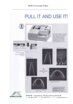
ThermoClamp™-1 and -2 Temperature Controller
User Manual
12
13
14
15
16
17
18
19
Q7
Q6
Q5
Q4
Q3
Q2
Q1
Q0
20
10
OE
1
U27
J27
15
14
13
12
+5
© 2005-2014 AutoMate Scientific, Inc.
AutoMate Scientific
®
ThermoClamp™-1 and -2 Temperature Controllers
User Manual
Table of Contents
Research Use Only
1
Packing list
2
Features and specifications
2
Acronyms, abbreviations and definitions
2
Electronic specifications
2
Components3
Controller unit
Perfusion Pencil
™
Perfusion Pencil Placement
3
4
5
Chemical Information
5
Getting started
6
Instructions for use
7
Adjusting the setpoint
7
Bath Perfusion / Water Jacket Feature
Making sure the device works properly
Autotuning the temperature controller
Other temperature controller parameters and features
Switching fluids
6
7
8
9
9
Operating without the bath sensor
10
Cutting the Pencil tips
10
Maintenance
10
Troubleshooting10
Overtemp / Thermocouple LED
Sensors
10
11
Replacement parts
12
Safety Instructions
12
Warranty13
Contact information
15
Research Use Only
The ThermoClamp is designed for solution-switching use in research applications ONLY. AutoMate
Scientific, Inc. cannot be responsible for injury or death resulting from medical or pharmacological use.
Packing list
Item
ThermoClamp™-1 or 2 temperature
controller
Heated Perfusion Pencil™ manifold
Bath thermocouple
Power cable
This ThermoClamp user manual
Fuji PXR3 controller user manual
Quantity
1
1
1
1
1
Download from ThermoClamp web page.
Also added after page 15 of this PDF.
Features and specifications
•
•
•
•
•
•
•
•
•
Auto-tuning PID (Proportional Integral Derivative) temperature control accurate to <1°C
4 to 8 channels for solution heating with flow rates up to 5cc/min @ 37˚C
Temperature controlled bath perfusion inline heater with a flow rate up to 5cc/min
Small manifold volume for rapid switching
Temperature can be maintained for the entire bath, or just for solutions being delivered
Perfusion Pencil tips are interchangeable / replaceable with standard AutoMate tips
Ramp and soak feature for automatically changing the set temperature over time
Low noise design for electrophysiology
Over-temperature protection
Electronic specifications
100-240V AC, 50-60 Hz, 80 Watts max (160 Watts ffor ThermoClamp-2)
Fuse: Replace external fuses only with UL 1 Amp 250V slow-blow (T 700mA L)
Replace internal fuse with 2.5 Amp 250V
This equipment must be earth grounded using the post on the back of the controller.
European CE Technical Representative:
AutoMate Scientific
Elisenstr. 16, Leverkusen 51373, Germany
Acronyms, abbreviations and definitions
CU
P-dP
Isopotential
PVOF
PID
TC
ThermoClamp Users Manual
Controller unit
Decimal place parameter
Grounding (earth) point
Process Variable Offset parameter
Proportional Integral Derivative
Thermocouple (temperature sensor)
2
Components
Controller unit
The Controller Unit (CU) is shown in Figures 1 and 2. The integrated temperature controller and power
supply for the heater are the main components of the controller unit.
Pencil
connector
Fuji temperature
controller
Power
switch
Figure 1. Controller unit, front view. (TC = thermocouple temperature sensor)
“Bath TC” in the above photo is now called “Control TC”, and “Pencil TC” is called “Safety TC” since
the ThermoClamp can be used in two different modes. The sensor plugged-in to the “Control” port is
used to control the temperature. The thermocouple in “Safety” is just used to prevent overheating of the
Pencil.
Power entry
module
Isopotential
(grounding)
point
Figure 2. Controller Unit, rear view.
NOTE: The ThermoClamp-1 and its heated Perfusion Pencil should both be grounded for high-gain
electrophysiology.
ThermoClamp Users Manual
3
Perfusion Pencil™
The Heated Perfusion Pencil™ (Pencil) manifold is shown in Figures 3, 4 and 5. The actual heating of
the drug solutions happens in the Pencil. The optional bath solution is also heated as it flows through the
Pencil.
Power
cables to
the CU
Thermal
insulation
Chamber
outflow
Drug flow orifice.
Tighten removable
tip for minimum
dead volume
Multiple solution
heater inflow
tubes
Chamber
bath inflow
Figure 3. Side view of the Perfusion Pencil.
TC cable to CU
Multiple solution
heater inflow
tubes
Pencil
mounting rod
Power cable
to the CU
Chamber
bath inflow
Figure 4. Detailed view of the rear part of the Perfusion Pencil.
ThermoClamp Users Manual
4
Figure 5. Heated Perfusion Pencil schematic.
Perfusion Pencil Placement
Your Heated Perfusion Pencil must be placed as close as possible to the perfusion chamber. If
it is too far away, the liquid in your tubes will lose all of its heat before it reaches the chamber. The
maximum distance between the Pencil and chamber depends on a number of variables including: tubing
material (thermal conduction), fluid dripping versus flowing into the perfusion chamber via submerged
tube, and ambient temperature and drafts. You may be able to mount your Pencil farther from the
chamber if you try double tubing between the two – use a piece of large Tygon tubing as thermal
insulation outside a small piece of Teflon tubing. Make sure your solution flows into your chamber
rather than dripping. The extra exposure to cool room air will greatly decrease the delivered liquid
temperature. Finally, avoid placing your chamber in a location where it is regularly blown by air drafts.
Many researchers purchase or build enclosures around their chambers or entire microscopes to help
control the temperature and avoid air drafts.
Chemical Information
The tubing inside the manifold body is polyimide (nylon). Additional connection tubing is
silicone. The removable tips include a medical-grade polypropylene Luer-lock fitting with a fused silica
(quartz) needle coated with polyimide. These materials are resistant to most acids, bases and organic
solvents. To avoid dust contamination, we recommend pre-rinsing the Perfusion Pencil and tip with
distilled water. Also, it is good practice to discard the first few microliters of solution before using
the device. The Heated Perfusion Pencil and removable tips are shipped non-sterile. The Pencil can
be chemically sterilized with cleaning solutions in each line. The removable tips can be chemically
sterilized or autoclaved. However, repeated autoclaving may weaken the adhesive bond between the
luer-lock fitting and the needle.
ThermoClamp Users Manual
5
Getting started
1.
2.
3.
4.
5.
6.
Connect the 7-pin Pencil connector to the ThermoClamp control box (CU).
Connect the Pencil thermocouple plug to the Safety TC socket.
Connect the bath thermocouple plug to the Control TC socket.
Connect the bath perfusion inflow tube to its fluid source. Notice the fragile capillaries.
Connect the bath perfusion outflow tube to the chamber. Notice the fragile capillaries.
Connect the drug tubes to their valves and reservoirs. Notice the fragile capillaries.
Warning: Do not leave any solution tubes at the rear of the Perfusion Pencil unconnected.
7. Fill and plug any unused drug tubes on the rear of the Perfusion Pencil to prevent backflow.
8. Connect the power cable to the CU via power entry module.
9. Ground the CU using the grounding post on the rear face, and the Pencil.
Bath Perfusion / Water Jacket Feature
The Heated Perfusion Pencil includes an extra tube for heating a flowing bath solution. This
heated high-flow line will maintain the bath temperature while quickly washing-out drugs applied
through the tip. The Pencil can maintain at least 37˚C with flow rates of 5cc/min.
This extra line can also be used with a water jacket on certain perfusion chambers. A “water
jacket” is usually a separate chamber or bath outside a perfusion chamber for circulating a heating
or cooling liquid. The perfusion chamber must be equipped with a water jacket. It is not usually
something that can be added later. Simply provide a high flow of water from a large reservoir through
the Pencil, into the chamber’s water jacket, and out to a drain or recirculating pump for ideal heating.
Reservoirs
with the drug
solutions
Bath and Pencil TCs
are connected to their
corresponding sockets
Chamber with
the cell under
examination
Chamber
heating fluid
source
Figure 6. Set up example of ThermoClamp temperature controller and accessories.
ThermoClamp Users Manual
6
Instructions for use
Making sure the device works properly
1. Connect both the bath and Pencil thermocouples.
2. Turn on the on the CU power switch. The temperature controller should display the ambient
temperature. If the “Pencil Max Temp” LED lights, check the Safety thermocouple plug. If the
temperature controller displays “UUUU”, check the Control thermocouple plug.
3. Adjust the setpoint above the ambient temperature. (Refer to the section on adjusting the
setpoint.) The controller will start heating the Pencil. If the controller has not been autotuned,
the temperature will probably overshoot. (Refer to the section on autotuning the temperature
controller.)
4. To verify that the Pencil does not leak internally, open the bath perfusion flow and all of the
delivery valves. Look for leaks at each end of the Pencil.
Adjusting the setpoint
The CU contains the PID (Proportional Integral Derivative) temperature controller Fuji PXR3, which
controls the temperature of the liquids in the Pencil.
Main display of PV (current temp),
SV (set value), or other parameter.
Red “Set Value”
(SV) indicator LED
Blinking rightmost decimal
point indicates autotuning in
progress.
Green “Control 1”
C1 LED = heating.
Select (SEL) key.
UP key.
DOWN key.
Figure 7. Faceplate of the Fuji temperature controller. NOTE: See also page 5 of the PXR3 manual.
To change the setpoint:
1. Press the SEL key and hold it until the SV light (red) turns on. Now the controller displays
the setpoint value.
2. With UP and DOWN keys adjust the temperature to the desired value.
3. Press and hold the SEL key again until the SV light turns off. Now the controller displays the
measured temperature.
NOTE: See also the separate manual for the Fuji controller for more details of the controller operation.
The Fuji PDF can be downloaded from AutoMate’s web site using the link at the bottom of:
http://www.autom8.com/thermoclamp.html
It has also been added to the end of the PDF version of THIS manual (after page 15).
ThermoClamp Users Manual
7
Autotuning the temperature controller
Since the Fuji temperature controller was designed as a generic temperature controller it needs
to be autotuned for the ThermoClamp system. During autotuning the controller determines the PID
coefficients and stores them in its nonvolatile memory. Autotuning of the controller must be done every
time physical parameters such as plumbing or flow rate are changed significantly.
To autotune the controller:
1. Open the bath solution flow to your desired flow rate, if you plan on using it.
2. Open one of the drug tubes with your normal drug delivery flow rate.
3. Turn on the CU.
4. Wait until the temperature in the Pencil reaches the vicinity of the setpoint.
5. If you plan on using the controller at a variety of temperatures or a ramp, consider using the
middle temperature as your setpoint.
6. Depress the SEL key on the controller until you see “STby” on the screen (3-6 sec.)
7. Press the DOWN key until you see “AT” (which looks like “A7”) on the screen.
8. Press the SEL key to change the value. It should read 0.
9. Press the UP key, until you see “1”, and press SEL to enter this value.
10.Hold the SEL button until the SV light turns on.
11.Press the SEL button again. Now the controller displays the measured temperature.
Autotuning can take up to several hours (usually under 30 minutes). During autotuning the
controller deliberately overheats the Pencil and flowing liquid several times, and then allows them to
cool below the setpoint. When the decimal point stops blinking, autotuning is finished.
The autotuning process does not always work. The decimal point may flash indefinitely. Two
possible reasons are variance in the system, and an open loop. Variance in the system means something
other than the ThermoClamp is affecting the system parameters while autotuning is happening. Three
possibilities are: another temperature controller is also being used simultaneously on the perfusion
chamber or stage, an exothermic reaction is occurring in the chamber (unlikely), or the bath liquid
level is changing enough during autotuning to affect the thermal inertia. Open loop means the
ThermoClamp’s feedback sensor is not working. The primary cause would be if the bath thermocouple
has fallen out of the bath or was unplugged. Make sure any other temperature controllers are turned off,
that the bath liquid level is stable, and the sensor remains in the bath. If the Fuji still will not autotune,
please see Troubleshooting section 13 on page 71 of the Fuji manual for further information, and
consider manually tuning the controller.
The PID parameters calculated by autotuning will be retained even if the power is lost. However,
if the power is turned off during the autotuning process, you must restart it. To abort the autotune
procedure, set AT to “0.” Autotuning has to be repeated if there is a significant change in setpoint, flow
rate, perfusion chamber or stage.
NOTE: Also see page 16 of the separate manual for the Fuji PXR3 for more details on controller
autotuning. For manual tuning, consider the Fuji default valves of P=5.0, I=240 sec., and D=60.0
sec.. Contact AutoMate Scientific if you would like further instructions in how to manually tune the
controller. If you plan on changing flow rates or setpoint temperature frequently, you may want to
consider either the “Fuzzy” logic or “Self” tuning control setting (see page 27 of Fuji manual).
IMPORTANT: If you are not using the bath perfusion line, autotune the controller without it
flowing.
ThermoClamp Users Manual
8
Other temperature controller parameters and features
To view or change the following parameters, press and HOLD the SEL key for about 3 seconds
until you see “P” on the display. Press UP/DOWN to advance through the different parameters. When
the desired parameter is displayed, press SEL to modify it, then UP/DOWN to make a change. Press
SEL for 3 seconds to return to the set temperature, and SEL again for operational mode.
1) Calibration. The “PVOF” or Process Variable Offset variable allows you to shift the
temperature controller’s measured temperature to match an actual temperature measured with a
calibrated thermometer. The value entered is a percentage of full scale from +/- 10%. Full scale is
determined by the maximum and minimum parameters described in number 3 below.
2) Decimal place. The “P-dP” parameter sets the number of decimal places displayed on your
temperature controller. The display can indicate integers, tenths or hundredths of a degree. The decimal
point position does not increase the accuracy of the controller, it only increases the resolution.
3) Maximum and minimum temperature parameter. The “P-SL” parameter sets the lowest
setpoint value, while the “P-SU” sets the highest desired temperature. This is simply a convenience
for entering your desired setpoint later, but it also determines “full-scale” for some internal controller
calculations.
4) Ramp. The Ramp/Soak program automatically changes the setpoint value over time according
to a preset pattern. See page 14 of the Fuji manual for a description of the variables necessary to start
and stop Ramp/Soak mode and how to change them. Then see pages 45-48 for a description of how to
set the four segments of ramp and soak.
See the Fuji manual for additional system parameters.
Switching fluids
While fluid remains stagnant within the Heated Pencil, its temperature will climb higher than
the setpoint. When you switch liquids, there will be a small temperature overshoot like the one shown
in Figure 8 below. When all solution flow is stopped, the ThermoClamp tries to maintain the desired
bath temperature by increasing heat to the Pencil. Without liquid flow, none of this added heat reaches
the chamber, so the Pencil continues heating until the overtemp LED lights. Consider turning-off the
temperature controller when liquids are not flowing.
36.8
36.6
36.4
Insulation, Bath 5cc/min
36.2
Overshoot
36
Insulation, no bath
35.8
Setpoint 37C
Drug 5cc/min
35.6
7/3/2003
35.4
-20
-10
0
10
20
30
40
50
Figure 8. Temperature vs. Time curves for fluid switching.
ThermoClamp Users Manual
9
Operating without the bath sensor
The bath thermocouple allows the ThermoClamp controller to monitor bath temperature and heat
your solutions in order to maintain the overall bath temperature. If you are using another controller to
maintain your bath temperature (with stage, chamber or objective heaters, etc.), then you do not want
the ThermoClamp to use the bath temperature for deciding whether to heat your solutions. If your other
temperature controller is doing a good job, then the ThermoClamp will always think that its liquids are
at the correct temperature, and will not apply any heat. Instead, it will be dispensing cold reagent into a
warmed chamber!
If you use another controller to maintain your chamber/bath temperature, or you do not wish to
use the ThermoClamp bath thermocouple, simply connect the Pencil’s thermocouple into the Control TC
socket. This way the ThermoClamp will observe and maintain the temperature of the Pencil irrespective
of the bath.
NOTE: the ThermoClamp will not operate (the “Max Temp” LED will light) if you try to use it
without anything plugged into the Safety TC socket. You must plug the unused bath thermocouple into
the Safety TC socket. Leave the bath thermocouple at room temperature.
In this configuration the temperature measured and displayed by the ThermoClamp will be
the internal temperature of the Perfusion Pencil, not the temperature of your chamber bath. If you
wish to maintain a particular bath temperature with flow from the Heated Pencil but without using the
bath sensor, you will need to measure the difference between the bath temperature and stable Pencil
temperature. Since the liquid will cool by several degrees before reaching the bath, you must set the
Pencil temperature setpoint higher by the observed offset.
Maintenance
You can expect several years of useful lifetime for your tip if you wash it daily. Use a syringe or
vacuum to pull water, then alcohol three times through the tip. If the Perfusion Pencil tip is filled with
pure salt solution, leaving it in the syringe overnight will not usually cause the tip to block. However, if
it is used for high viscosity fluids, flushing after each use is recommended.
Cutting the Pencil tips
The removable tips are shipped with 1.5” (3.8 cm) length polyimide needles. They are intended
to be cut to a desired length by rolling a razor blade on them against a hard surface. However, this may
leave a small crack or barb on the tip. To get a flat cut, score the coating of the needle with a ceramic
cleaving stone or a diamond cutter and pull directly apart, making sure not to pull at an angle. You may
notice a larger outer tube enclosing the lower part of our smaller, 100 µm needles. This is simply for
added rigidity and can be cut if needed.
Troubleshooting
Pencil Max Temp / Thermocouple LED
The ThermoClamp is equipped with a warning light. These will warn you of an overtemp or
broken thermocouple situation. If the LED lights during use, it means that either the Pencil has reached
its maximum temperature, or its thermocouple has broken. This is not necessarily a problem. The LED
may illuminate while heating a cold perfusion chamber. The overtemp circuit will reset itself once the
temperature drops. You do not need to do anything except remedy the cause of the high temperature and
allow the Pencil to cool following the instructions below.
ThermoClamp Users Manual
10
Here is an example of an overtemp situation. If you leave the bath thermocouple sitting on a cold table
while the ThermoClamp is running, the controller will think that the bath temperature is significantly
below your setpoint. It will apply heat to the Pencil, but will not observe an increase in the “bath.” It
will continuing heating the Pencil indefinitely. The overtemp sensor automatically turns-off heat to the
Pencil and lights the indicator LED once the Pencil reaches a pre-set maximum.
The LED will also alert you if the Pencil thermocouple is broken or not plugged-in. If you
wish to operate the ThermoClamp without a bath sensor, and you plug the Pencil thermocouple into the
Control TC socket, then you must plug the bath thermocouple into Safety TC. See the preceding section
called “Operating without the bath sensor.”
Troubleshooting -- If the LED lights, check the following:
1)Is a thermocouple plugged into the Safety TC socket on the controller?
2)Is the bath sensor in the bath (or desired location)?
3)Has liquid flow been off for a long time? Consider turning off the temperature
controller when liquids are not flowing.
4)If the Pencil feels hot (WARNING: the metal surface of the Pencil can get very hot!),
turn-off the controller and wait for a few minutes. Running liquids (buffer and/or
inexpensive drug) through the Pencil will cool it more quickly. Do NOT apply liquid
to the outside of the Pencil or submerge it in liquid. This may permanently damage the
Pencil.
5)If the LED does not go off even after the Pencil has cooled, you may have a broken
thermocouple inside your Pencil. You can measure the resistance at the PENCIL
TC plug. If it is infinite, then the wire or thermocouple has broken. Please contact
AutoMate Scientific about a repair or replacement.
NOTE: The overtemp circuit has been factory set at a safe temperature for the Pencil. Despite
the warning light, nothing in the ThermoClamp system is harmed at the alarm temperature, even longterm.
Sensors
Several problems can arise with your ThermoClamp sensors. One of the simplest problems is
having the bath sensor fall out of the bath. The bath sensor must be in good thermal contact with the
bath solution. The insulation on the bath sensor can also degrade until the bath solution makes electrical
contact with the thermocouple. If the control unit displays “UUUU”, the bath sensor may be shorting
to the bath solution. Try removing the sensor from the bath to see if the “UUUU” disappears. Make
sure you are not grounding the thermocouple with your fingers. If you suspect broken insulation on the
thermocouple, dip it in epoxy and allow it to dry.
The thermocouples or their wires or plugs can break. This is easy to observe with a multimeter
(ohmmeter) as an infinite resistance measurement. Check inside the sensor’s blue plug for a loose screw.
The sensors are simply two different thermocouple wires soldered together. It may be possible to solder
them back together if you can find the break. Remove any oxidation build-up on the plugs.
It may be possible for the Pencil TC to short to the inside of the Pencil. This can be observed as
a zero resistance between the Pencil TC plug (either lead) and the metal Pencil body. If you suspect a
shorted Pencil TC, carefully remove the Pencil’s “wetsuit.” Remove two screws holding the top of the
Pencil. You can see the Pencil TC at the end of its two wires. Dip the ends of the bare wires into some
ThermoClamp Users Manual
11
epoxy for insulation and allow to dry. Reassemble and test the Pencil.
The ThermoClamp-1 uses standard T-type thermocouples for bath and Pencil.
Finally, we wanted to mention that most digital voltmeter thermometers with thermocouples are
only accurate to +/- 2˚C. Unless you perform a multi-point calibration on your digital thermometer, it
should probably not be trusted to calibrate your ThermoClamp. Ice water is always a good 0˚C test.
Replacement parts
Part No.
04-360
04-250
04-100
Description
360 µm Removable Tip
250 µm Removable Tip
100 µm Removable Tip
03-08-xxx
Heated Perfusion Pencil [8-channel with xxx size tip]
03-08
Replacement Heated Perfusion Pencil [8-channel]
Heated Pencil “wetsuit”
ThermoClamp-1 Control Unit
03-sensor
Bath thermocouple sensor
Safety Instructions
The following instructions pertain to the risk of fire, electric shock, or bodily injury. Please read all of
these instructions carefully.
1. Follow all the instructions and warnings marked on this product and included in this manual.
2. Do not use this product on an unstable cart, stand, or table. This product may fall, causing serious
damage to the product.
3. Slots and openings in the cabinet and the back are provided for ventilation. To ensure the reliable
operation of your product, and to protect it from overheating, these openings must not be blocked or
covered. Do not use this product on a bed, sofa, rug or other similar surfaces. This product should
never be placed near or over a radiator or heat register. This product should not be placed in a built-in
installation unless proper ventilation is provided.
4. Never push objects of any kind into the product through the cabinet openings, as they may touch
dangerous voltage points or short-out parts that could result in fire or electric shock. Never spill liquids
of any kind in the product.
5. This product should only be connected to the AC power source indicated on your product system’s
information label. If you are not sure of the type of AC power available, consult your dealer or local
power company. Only connect this product to a power outlet that matches the power requirements of
this product.
6. Do not allow anything to rest on the power cord. Do not locate this product where people will walk
on the cord.
ThermoClamp Users Manual
12
7. If you have to use an extension cord with this product, make sure that the total amperage rating of all
equipment plugged into it does not exceed the amperage rating of the extension cord. Also, make sure
that the total of all products plugged into the main AC power outlet does not exceed 15 Amps.
8. Unplug your product from the main electrical power before cleaning. Do not use liquid cleaner or
aerosol cleaners. Use a damp cloth for cleaning.
9. Do not use this product near water.
10. Unplug this product from the main power outlet and call for service under any of the following
conditions:
A.
B.
C.
D.
E.
If the power cord or plug is damaged or frayed.
If liquid has been spilled into the product.
If the product has been exposed to rain or water.
If the product has been dropped or the cabinet has been damaged.
If the product exhibits a distinct change in performance, indicating a need for service.
STOP!!
If you ever have to remove the main system unit cover, observe the following precautions:
A. The power supply cord must be unplugged before the main system unit cover is removed. (Separe le
cordon d’alimantation et puis enleve le couvercle.)
B. Once removed, the cover must be replaced and screwed in position before the power supply is
plugged back in. (Apres le couvercle en place et remettre le cordon d’alimentation.)
Warranty
AutoMate Scientific, Inc. warrants its products against defects of workmanship and/or material
for ONE YEAR from the date of sale. Any product that fails to perform as specified may be returned,
freight pre-paid to the factory (with a written explanation of the problem) for examination and repair
or replacement. If it is defective, AutoMate Scientific will repair or replace (at our option) the product
without charge and return it to you.
If the examination indicates that non-compatible fluid, destructive environment, accidental
damage, modification or abusive practices have occurred, all labor, materials and freight costs shall be at
the expense of the customer.
Due to the nature of clinical laboratory applications, AutoMate Scientific, Inc. will NOT accept
the return of any products which have been used with HAZARDOUS MATERIALS or in a harmful
environment. This warranty is in lieu of all other warranties, whether oral or written, express or implied.
In no event shall AutoMate Scientific, Inc. or its licensor/licensees be liable for contingent, special,
direct, indirect or consequential damages for the breach of any express or implied warranty or resulting
from the use, failure or malfunction of any product, including damage to property and, to the fullest
extent permitted by law, damages for personal injury, even if AutoMate Scientific, Inc. has been advised
of the possibility of such damages or if this warranty is found to fail its essential purpose. AutoMate
ThermoClamp Users Manual
13
Scientific, Inc’s liability is limited to the reimbursement of the cost of the product. All other warranties,
including, but not limited to warranties for fitness or merchant ability for a particular purpose are
expressly excluded. No verbal changes to this policy will be authorized.
AutoMate Scientific, Inc. manufacturers and sells goods in accordance with U.S. federal, state
and local laws, but assumes no responsibility or liability for laws, regulations, duties, or taxes imposed
by any foreign country. All terms and conditions hereof shall be governed by the laws of the State of
California.
ThermoClamp Users Manual
14
AutoMate Scientific
®
Contact information
AutoMate Scientific, Inc.
812 Page St
Berkeley, California 94710
USA
[email protected]
http://www.autom8.com
Phone 510-845-6283
Free 800-998-MATE (6283)
Fax 510-280-3795


![[MI 611-227] 875 Series Intelligent Analyzers - Operation](http://vs1.manualzilla.com/store/data/005865143_1-5593040b74ad0b0d98c6c04fef25d9eb-150x150.png)