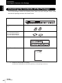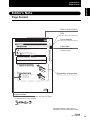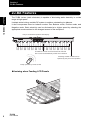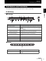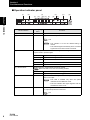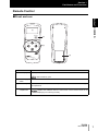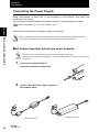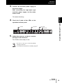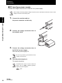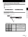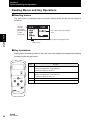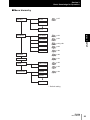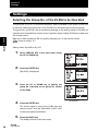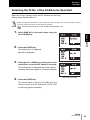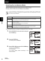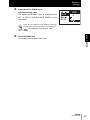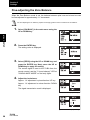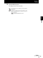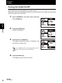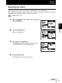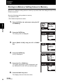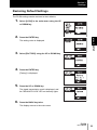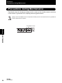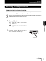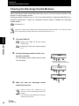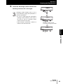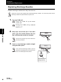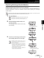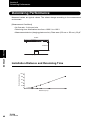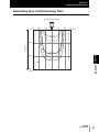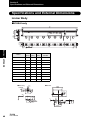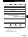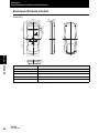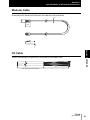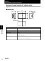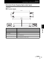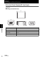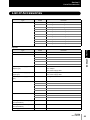
1
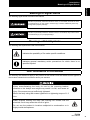
Ionizer
Bar Type
ZJ-BA Series
User's Manual
Cat. No. Z235-E1-01
Introduction
Thank you for purchasing the ZJ-BA.
This manual provides information regarding functions, performance and operating methods that
are required for using the ZJ-BA.
When using the ZJ-BA, be sure to observe the following:
• The ZJ-BA must be operated by personnel knowledgeable in electrical engineering.
• To ensure correct use, please read this manual thoroughly to deepen your understanding of the
product.
• Please keep this manual in a safe place so that it can be referred to whenever necessary.
Section 1 OVERVIEW
Section 2 INSTALLATION & CONNECTION
Section 3 SETUP
Section 4 MAINTENANCE
Section 5 APPENDIX
User's Manual
Ionizer
ZJ-BA Series
Introduction Section 1 Section 2 Section 3 Section 4 Section 5
Introduction APPLICATION CONSIDERATIONS (Please Read)
Introduction
Introduction
READ AND UNDERSTAND THIS DOCUMENT
Please read and understand this document before using the products. Please consult your OMRON
representative if you have any questions or comments.
WARRANTY
OMRON’s exclusive warranty is that the products are free from defects in materials and workmanship for
a period of one year (or other period if specified) from date of sale by OMRON.
OMRON MAKES NO WARRANTY OR REPRESENTATION, EXPRESS OR IMPLIED, REGARDING
NON-INFRINGEMENT, MERCHANTABILITY, OR FITNESS FOR PARTICULAR PURPOSE OF THE
PRODUCTS. ANY BUYER OR USER ACKNOWLEDGES THAT THE BUYER OR USER ALONE HAS
DETERMINED THAT THE PRODUCTS WILL SUITABLY MEET THE REQUIREMENTS OF THEIR
INTENDED USE. OMRON DISCLAIMS ALL OTHER WARRANTIES, EXPRESS OR IMPLIED.
LIMITATIONS OF LIABILITY
OMRON SHALL NOT BE RESPONSIBLE FOR SPECIAL, INDIRECT, OR CONSEQUENTIAL
DAMAGES, LOSS OF PROFITS OR COMMERCIAL LOSS IN ANY WAY CONNECTED WITH THE
PRODUCTS, WHETHER SUCH CLAIM IS BASED ON CONTRACT, WARRANTY, NEGLIGENCE, OR
STRICT LIABILITY.
In no event shall responsibility of OMRON for any act exceed the individual price of the product on which
liability is asserted.
IN NO EVENT SHALL OMRON BE RESPONSIBLE FOR WARRANTY, REPAIR, OR OTHER CLAIMS
REGARDING THE PRODUCTS UNLESS OMRON’S ANALYSIS CONFIRMS THAT THE PRODUCTS
WERE PROPERLY HANDLED, STORED, INSTALLED, AND MAINTAINED AND NOT SUBJECT TO
CONTAMINATION, ABUSE, MISUSE, OR INAPPROPRIATE MODIFICATION OR REPAIR.
ii
ZJ-BA
User’s Manual
Introduction
THE PRODUCTS CONTAINED IN THIS DOCUMENT ARE NOT SAFETY RATED. THEY ARE NOT
DESIGNED OR RATED FOR ENSURING SAFETY OF PERSONS, AND SHOULD NOT BE RELIED
UPON AS A SAFETY COMPONENT OR PROTECTIVE DEVICE FOR SUCH PURPOSES.
Please refer to separate catalogs for OMRON’s safety rated products.
Introduction
SUITABILITY FOR USE
OMRON shall not be responsible for conformity with any standards, codes, or regulations that apply to
the combination of products in the customer’s application or use of the product.
At the customer’s request, OMRON will provide applicable third party certification documents identifying
ratings and limitations of use that apply to the products. This information by itself is not sufficient for a
complete determination of the suitability of the products in combination with the end product, machine,
system, or other application or use.
The following are some examples of applications for which particular attention must be given. This is not
intended to be an exhaustive list of all possible uses of the products, nor is it intended to imply that the
uses listed may be suitable for the products:
• Outdoor use, uses involving potential chemical contamination or electrical interference, or conditions or
uses not described in this document.
• Nuclear energy control systems, combustion systems, railroad systems, aviation systems, medical
equipment, amusement machines, vehicles, safety equipment, and installations subject to separate
industry or government regulations.
• Systems, machines, and equipment that could present a risk to life or property.
Please know and observe all prohibitions of use applicable to the products.
NEVER USE THE PRODUCTS FOR AN APPLICATION INVOLVING SERIOUS RISK TO LIFE OR
PROPERTY WITHOUT ENSURING THAT THE SYSTEM AS A WHOLE HAS BEEN DESIGNED TO
ADDRESS THE RISKS, AND THAT THE OMRON PRODUCT IS PROPERLY RATED AND INSTALLED
FOR THE INTENDED USE WITHIN THE OVERALL EQUIPMENT OR SYSTEM.
PERFORMANCE DATA
Performance data given in this document is provided as a guide for the user in determining suitability and
does not constitute a warranty. It may represent the result of OMRON’s test conditions, and the users
must correlate it to actual application requirements. Actual performance is subject to the OMRON
Warranty and Limitations of Liability.
CHANGE IN SPECIFICATIONS
Product specifications and accessories may be changed at any time based on improvements and other
reasons.
It is our practice to change model numbers when published ratings or features are changed, or when
significant construction changes are made. However, some specifications of the product may be
changed without any notice. When in doubt, special model numbers may be assigned to fix or establish
key specifications for your application on your request. Please consult with your OMRON representative
at any time to confirm actual specifications of purchased products.
ZJ-BA
User’s Manual
iii
Introduction
Introduction
DIMENSIONS AND WEIGHTS
Dimensions and weights are nominal and are not to be used for manufacturing purposes, even when
tolerances are shown.
ERRORS AND OMISSIONS
The information in this document has been carefully checked and is believed to be accurate; however, no
responsibility is assumed for clerical, typographical, or proofreading errors, or omissions.
PROGRAMMABLE PRODUCTS
OMRON shall not be responsible for the user’s programming of a programmable product, or any
consequence thereof.
COPYRIGHT AND COPY PERMISSION
This document shall not be copied for sales or promotions without permission.
This document is protected by copyright and is intended solely for use in conjunction with the product.
Please notify us before copying or reproducing this document in any manner, for any other purpose. If
copying or transmitting this document to another, please copy or transmit it in its entirety.
iv
ZJ-BA
User’s Manual
Introduction
Meanings of Signal Words
Introduction
Meanings of Signal Words
The following signal words are used in this manual.
Indicates a potentially hazardous situation which, if not avoided, will result in minor
or moderate injury, or may result in serious injury or death. Additionally there may
be significant property damage.
Indicates a potentially hazardous situation which, if not avoided, may result in minor
or moderate injury or in property damage.
Meanings of Alert Symbols
The following alert symbols are used in this manual.
Indicates the possibility of fire under specific conditions.
Indicates general mandatory action precautions for which there is no
specified symbol.
Alert Statements in this Manual
The following alert statements apply to the products in this manual. Each alert statement also appears at
the locations needed in this manual to attract your attention.
When screw-fastening the body for use by the mounting bracket,
vibration or the body's own weight may cause it to fall, and cause an
injury if the screws are not sufficiently tightened.
Mount the body using M4 screws tightened to a tightening torque of 1.2
N•m.
Water droplets entering the body and coming into contact with the
electrical circuit may cause the circuit to ignite.
Do not use the product in locations subjected to condensation or in
highly humid atmospheres.
ZJ-BA
User’s Manual
v
Introduction
Precautions for Safe Use
Introduction
Precautions for Safe Use
Please observe the following precautions for safe use of the product.
1.Installation Environment
• Do not use the product in environments where it can be exposed to inflammable/
explosive gas.
• Do not install the product close to high-voltage devices and power devices in order to
secure the safety of operation and maintenance.
2.Power Supply and Wiring
• Use the power supply within the specified voltage range.
• The output load should not be short-circuited.
• High-voltage lines and power lines must be wired separately from this product. Wiring
them together or placing them in the same duct may cause induction, resulting in
malfunction or damage.
• Avoid connecting or disconnecting connectors while the product is powered on. Doing
so may damage the product.
3.Others
• Use only the specified types of batteries for the exclusive remote control.
Also, before using the remote control, be sure to thoroughly read the precautions
provided by the manufacturer to ensure correct use.
• Do not disassemble, repair, or modify this product.
• Dispose of this product as industrial waste.
vi
ZJ-BA
User’s Manual
Introduction
Precautions for Correct Use
Introduction
Precautions for Correct Use
Please observe the following precautions to prevent failure to operate, malfunctions, or undesirable
effects on product performance.
1.Installation Site
Do not install this product in locations subjected to the following conditions:
• Ambient temperature outside the rating
• Ambient humidity outside the rating
• Presence of corrosive or flammable gases
• Presence of dust, salt, or iron particles
• Direct vibration or shock
• Direct sunlight
• Water, oil, or chemical fumes or spray
• Strong magnetic or electric field
• Devices (e.g. precision equipment) susceptible to the influence of peripheral noise
2.Power Supply and Wiring
• Be sure to use the exclusive power supply (AC adapter type, high-output type or DC
input type). Also, use the exclusive modular cable for wiring the exclusive power
supply to the ionizer.
• The maximum number of ionizers that can be connected to each of the exclusive
power supplies is already determined. Be sure to observe these limitations.
• When using an exclusive power supply (DC input type)
•When connecting the DC24V input terminals, pay attention to the polarity of the
terminals. The supply voltage must be within the rated range.
•Do not ground the DC24V terminal.
• If surge currents are present in the power lines, connect surge absorbers that suit the
operating environment.
• When connecting the I/O signal lines, pay attention to the polarity of the lines. The
supply voltage and current must be within the rated ranges.
3.Maintenance and Inspection
• Periodically clean the discharge needles as dirt on these needles causes the amount
of generated ions to fall or the ion balance to deviate.
• Before cleaning or removing/installing discharge needles, be sure to turn the power
off.
• Do not touch the discharge needles directly with your hands.
• Use alcohol for cleaning the discharge needles.
Do not use paint thinner, benzene, acetone or kerosene.
• Do not directly touch the ion balance sensors (3 at center and at both sides) of the
body.
ZJ-BA
User’s Manual
vii
Introduction
Checking the Contents of the Package
Introduction
Checking the Contents of the Package
The ZJ-BA package contains the following items. Before you start using the ZJ-BA, make
sure that the package contains all of these items.
Body
Mounting bracket (with M4 screws):
2 pcs
Bracket (without screws)
• 2 pcs: BA049/BA073/BA097
• 3 pcs: BA121/BA145/BA169
• 4 pcs: BA193/BA217/BA265
Warning label (English): 1 (*1)
User's Manual (this document)
(1 pc)
Ionizer
Bar Type
ZJ-BA series
User's Manual
*1:
Reattach the warning label as necessary.
Re-attach the warning label over the label (Japanese) on the right edge of the body.
viii
ZJ-BA
User’s Manual
Introduction
Editor's Note
Introduction
Editor's Note
Page Format
Title of each section
Title
Cross-header
Section 2
Installation
Installation
Maintain space around the ZJ-BA for installation.
Checking the installation site p.10
Multiple ZJ-BAs can also be serially connected.
Serially Connecting Two or More ZJ-BAs p.3
CAUTION
When installing the ZJ-BA, pay attention to the protrusions on the three ion
balance sensors to prevent injury to your eyes or body.
Do not apply force in the horizontal direction to the three ion balance sensors on
Section 2 INSTALLATION & CONNECTION
Installing the ZJ-BA
Index label
Indicates the section
number and title.
the ZJ-BA. Doing so may cause damage.
1.
2.
Remove one of the mounting brackets
supplied on both ends of the body.
Insert the brackets into the body.
Explanation of procedure
The following shows the number of brackets to be used.
. ZJ-BA049/073/097: 2 pcs
. ZJ-BA121/145/169: 3 pcs
. ZJ-BA193/217/241/265: 4 pcs
ZJ-BA
ZJ
-BA
User's Manual
11
Supplementary
Helpful information regarding operation and reference pages
are introduced here using symbols.
* This page has been made purely for
explanatory purposes and does not exist.
ZJ-BA
User’s Manual
ix
Introduction
Editor's Note
Introduction
■ Meaning of Symbols
Menu items that are displayed on the remote control's LCD screen are indicated
enclosed by brackets "[ ]".
■ Visual Aids
Indicates points that are important to ensure full product performance, such as operational
precautions and application procedures.
(upper row: when used in text descriptions other than tables)
(lower row: when used in tables)
Indicates pages where related information can be found.
Indicates information helpful in operation.
x
ZJ-BA
User’s Manual
Introduction
CONTENTS
CONTENTS
CONTENTS
Meanings of Signal Words
v
Meanings of Alert Symbols
v
Alert Statements in this Manual
v
Precautions for Safe Use
vi
Precautions for Correct Use
vii
Checking the Contents of the Package
viii
Editor's Note
Page Format
CONTENTS
ix
ix
xi
Section 1 OVERVIEW
1
ZJ-BA Features
2
Basic Configuration
3
Part Names and Functions
5
ZJ-BA Body
5
Remote Control
7
Section 2 INSTALLATION & CONNECTION
Before Installation and Connection
Precautions for the Installation Site
Installation
Installing the ZJ-BA
Connection
9
10
10
11
11
13
Connecting the Air Tube
13
Connecting the Power Supply
14
Serially Connecting Two or More ZJ-BAs
17
Connecting the I/O Cable
17
ZJ-BA
User’s Manual
xi
Introduction
CONTENTS
CONTENTS
Section 3 SETUP
ID No. Setting
20
Basic Knowledge for Operation
21
Features of the Remote Control
21
Reading Menus and Key Operations
22
Settings
24
Selecting the Group No. of the ZJ-BA to be Operated
24
Selecting the ID No. of the ZJ-BA to be Operated
25
Selecting the Ion Balance Mode
26
Fine-adjusting the Zero Balance
28
Turning the ZJ-BA On/Off
30
Resetting the Alarm
31
Storing Ion Balance Setting Values to Memory
32
Restoring Default Settings
33
Section 4 MAINTENANCE
xii
19
35
Precautions during Maintenance
36
Cleaning and Replacement
37
ZJ-BA
Cleaning the Discharge Needles
37
Cleaning the Discharge Needle Modules
38
Replacing Discharge Needles
40
Replacing Discharge Needle Modules
41
User's manual
Introduction
CONTENTS
43
Troubleshooting
44
Glossary
45
Deionizing Performance
46
Installation Distance and Deionizing Time
46
Deionizing Area and Deionizing Time
47
Specifications and External Dimensions
CONTENTS
Section 5 APPENDIX
48
Ionizer Body
48
Exclusive Remote Control
50
Modular Cable
51
I/O Cable
51
Exclusive Power Supply (AC adapter type)
52
Exclusive Power Supply (high-output type)
53
Exclusive Power Supply (DC input type)
54
List of Accessories
55
INDEX
57
Revision History
62
ZJ-BA
User’s Manual
xiii
Introduction
CONTENTS
CONTENTS
xiv
MEMO
ZJ-BA
User's manual
Section 1 OVERVIEW
Section 1
OVERVIEW
ZJ-BA Features
2
Basic Configuration
3
Part Names and Functions
5
ZJ-BA Body
5
Remote Control
7
ZJ-BA
User’s Manual
1
Section 1
ZJ-BA Features
ZJ-BA Features
Section 1 OVERVIEW
The ZJ-BA ionizer (static eliminator) is capable of eliminating static electricity in a wide
range at high speed.
It adopts a dual mixing variable DC system to achieve outstanding ion balance.
It also incorporates three ion balance modes: Zero Balance mode, Positive mode, and
Negative mode. Static electricity can be eliminated at a higher speed by selecting the
appropriate mode matched to the charged amount of the workpiece.
Easy-to-understand operation state display
Ion balance sensors are mounted at both ends and
at the center to automatically control the ion balance.
Discharge needle modules can be
replaced by easy one-touch operation.
BA
UP
CK
DO
W SE
N LE
CT
Easily operable by remote control
● Ionizing when Feeding LCD Panels
2
ZJ-BA
User’s Manual
Section 1
Basic Configuration
Basic Configuration
Section1 OVERVIEW
The basic configuration changes according to the type of power supply used.
Body
ZJ-BA
Modular cable
ZJ-BA-MC
(2 m/5 m/10 m/15 m/20 m)
Used for connecting two
ZJ-BAs or exclusive
power supplies.
I/O cable
ZJ-BA-FC
(2 m/5 m/10 m/15 m/20 m)
Used for connecting to
external devices.
UP
CT
LE
SE
N
W
CK DO
BA
Exclusive remote control
ZJ-BA-R01
Exclusive power supply
Select from the following three types.
●AC adapter type
ZJ-BA-PS01
AC 100
Adapter box
AC adapter
AC power
supply cable
●High-output type
AC 100
ZJ-BA-PS02
AC power supply
●DC input type
AC power
supply cable
DC 24 V
ZJ-BA-PT01
Voltage
conversion box
The number of connectable units changes according to the type of power supply.
Number of Connectable Units by Exclusive Power Supply p.4
ZJ-BA
User’s Manual
3
Section 1
Basic Configuration
■ Number of Connectable Units by Exclusive Power Supply
The maximum length of the modular cable differs according to how the ionizer is
connected.
Section 1 OVERVIEW
Type
AC adapter type
ZJ-BA-PS01
Number of
Connectable
Units
Connection Example
2 units
AC adapter
Adapter
box
ZJ-BA
AC power
supply cable
20 m (max)
Modular cable
AC adapter
Adapter
box
AC power
supply cable
High-output type
ZJ-BA-PS02
ZJ-BA
10 m (max)
ZJ-BA
10 m (max)
8 units
ZJ-BA
AC power supply ZJ-BA
AC power
supply cable
10 m (max)
10 m (max)
* Up to three ZJ-BAs can be connected to a single modular
connector.
AC power supply
AC power
supply cable
DC input type
ZJ-BA-PT01
ZJ-BA
ZJ-BA
ZJ-BA
6 m (max)
6 m (max)
6 m (max)
2 units
Voltage
conversion box
ZJ-BA
DC 24 V
0.78 A
20 m (max)
Voltage
conversion box
DC 24 V
0.78 A
4
ZJ-BA
User’s Manual
ZJ-BA
ZJ-BA
10 m (max)
10 m (max)
Section 1
Part Names and Functions
Part Names and Functions
Section1 OVERVIEW
This section describes the names and functions of parts on the ZJ-BA.
ZJ-BA Body
■ Front/side
(9)
(6)
(7)
(8)
(1)
(1)
(2)
(2)
(3)
(4)
(4)
(4)
(4)
(4)
(4)
(5)
(4)
(5)
(2)
(3)
(5)
Name
Function
(1)
Power connector
For connecting to the exclusive power supply by the modular cable
(2)
Air intake duct
A 6 mm dia. air tube is connected to allow air in.
This duct is provided on only one side of the JZ-BA049/
073/097.
(3)
Discharge needle modules
(single-pole specification)
A high voltage is applied to the tips of these needles, and ions are
discharged from only one side by corona discharge.
(4)
Discharge needle modules
(both-pole specification)
A high voltage is applied to the tips of these needles, and ions are
discharged from both sides by corona discharge.
(5)
Ion balance sensor
This sensor maintains a constant balance between plus ions and
minus ions.
(6)
Group No. display
Indicates the group No.
(7)
DIP switch
Sets the ID No. of the body.
(8)
Operation indicator panel
Indicates the operating state of the body and function settings.
(9)
I/O cable connector
This connector is for connecting the I/O cable.
■ Bottom
(1)
Name
(1)
Air spray hole
Function
Plus/minus ions are sprayed onto the charged object from
this hole.
ZJ-BA
User’s Manual
5
Section 1
Part Names and Functions
■ Operation indicator panel
(1)
(2)
(3)
Section 1 OVERVIEW
[1]
[2]
(4)
[3] [4]
[5]
[6]
(5)
(6)
[7]
ON
1
2
3
4
Panel Indication
LED Lighting
Color
Functions
(1) POWER
Red
Lights when the ionizer is powered on.
(2) BALANCE LOCK
Red
Lights when the body is locked.
p.32
• This indicator is lit as the default setting is
locked.
• This indicator lights momentarily when a wireless
signal from the remote control is received.
(3) ION BALANCE MODE The currently selected ion balance mode lights in five stages.
Only the mode in question lights.
(4) ION OUTPUT
(5) CLEANING
[1] -H: Red
Lights when the Negative High mode is selected.
[2] -L: Orange
Lights when the Negative Low mode is selected.
[3] 0: Green
Lights when the Zero Balance mode is selected.
[4] +L: Orange
Lights when the Positive Low mode is selected.
[5] +H: Red
Lights when the Positive High mode is selected.
Indicates that ions of both polarity are being emitted.
When this LED is out, ions are not being emitted.
[6] -: Green
Lights when minus ions are being generated.
[7] +: Red
Lights when plus ions are being generated.
Red
Lights when the discharge needles are dirty, which causes a
drop in ion output.
• This LED is enabled only when the panel
indicates the Zero Balance mode.
• This LED indicator also lights together with the
ALARM LED when it is lit.
(6) ALARM
Red
This LED lights when an error occurs.
Ion output stops when this LED is lit.
p.31
6
ZJ-BA
User’s Manual
Section 1
Part Names and Functions
Remote Control
Section1 OVERVIEW
■ Front and rear
(1)
ON/OFF
(2)
UP
BACK
ENTER
(3)
DOWN
(4)
ZJ-BA-R01
REMOTE CONTROLLER
MADE IN JAPAN
Name
(1) LCD display
Function
Displays the menu.
Menu hierarchy p.23
(2) Power supply
switch
Turns the remote control ON/OFF.
(3) Control keys
The UP, DOWN, BACK, and ENTER keys select menus, and are used for settings
and operations.
(4) Battery
compartment
Holds three AAA batteries.
Replace the batteries when the LCD screen of the remote control is not
displaying or functioning correctly.
ZJ-BA
User’s Manual
7
Section 1
Part Names and Functions
MEMO
Section 1 OVERVIEW
8
ZJ-BA
User’s Manual
Section 2
INSTALLATION & CONNECTION
Precautions for the Installation Site
Installation
Installing the ZJ-BA
Connection
Section 2 INSTALLATION & CONNECTION
Before Installation and Connection
10
10
11
11
13
Connecting the Air Tube
13
Connecting the Power Supply
14
Serially Connecting Two or More ZJ-BAs
17
Connecting the I/O Cable
17
ZJ-BA
User’s Manual
9
Section 2
Before Installation and Connection
Before Installation and Connection
Precautions for the Installation Site
■ Checking the installation environment
Sectino 2 INSTALLATION & CONNECTION
Read "Precautions for Safe Use" at the beginning of this manual, and check the
installation environment.
■ Checking the installation site
Read "Precautions for Correct Use" at the beginning of this manual, and check the
installation site.
■ Installation site and installation distance
• When installing the body on a wall or similar surface, allow at least 30 mm between
the body and the installation surface.
• We recommend 300 mm to 1500 mm of space between the body and the object to be
deionized. Plus ions and minus ions are simultaneously emitted in this range to
uniformly deionize the object.
30 mm min.
Distance to object to be deionized
is 300 mm to 1500 mm.
• Do not place charged objects within about 100 mm around the body (excluding the ion
spray position). Otherwise, the performance of the ZJ-BA may be adversely affected.
Do not place charged objects
or ungrounded metal objects
within 100 mm around the body.
• Ground ungrounded metal objects.
• Other ionizers used near to the ZJ-BA may adversely affect deionizing performance.
• Prevent metal from contacting metal parts on the side and bottom of the body, and the sensor
electrodes. Failure to do so might adversely affect deionizing performance.
10
ZJ-BA
User’s Manual
Section 2
Installation
Installation
Installing the ZJ-BA
Maintain space around the body for installation.
Section 2 INSTALLATION & CONNECTION
Checking the installation site p.10
Multiple ZJ-BAs can also be serially connected.
Serially Connecting Two or More ZJ-BAs p.4, p.17
When installing the ZJ-BA, pay attention to the protrusions on the
three ion balance sensors to prevent injury to your eyes or body.
Do not apply force in the horizontal direction to the three ion balance
sensors on the ZJ-BA. Doing so may cause damage.
1.
Remove one of the mounting brackets
supplied on both ends of the body.
2.
Insert the brackets into the body.
The following shows the number of supplied
brackets:
• ZJ-BA049/073/097: 2 pcs
• ZJ-BA121/145/169: 3 pcs
• ZJ-BA193/217/241/265: 4 pcs
Position the brackets at equal distances along
the body.
ZJ-BA
User’s Manual
11
Section 2
Installation
3.
Install
the
mounting
bracket
you
removed onto the body.
Screws: M4 x 2
Sectino 2 INSTALLATION & CONNECTION
4.
Fix
the
mounting
bracket
at
the
installation site using the M4 screws.
Screws: M4 x 2
I.D
NO
POWE
R
Tightening torque: 1.2 N•m
5.
BALAN
LOCKCE
-H
-L
ZJ-B
A
ION
0
BALAN
+L
CE
AIR
MODE
+H
ION
CLEAN
CLEAN
PU
ING
RG
E ION
IZE
R
ALARM
Fix the bracket using M4 screws.
Screws: M4 x 2 per bracket
Tightening torque: 1.2 N•m
I.D
NO
POWE
R
BALAN
LOCKCE
-H
-L
ZJ-B
A
ION
0
BALAN
CE
AIR
12
ZJ-BA
User’s Manual
+L
MODE
+H
ION
CLEAN
CLEAN
PU
ING
RG
E ION
IZE
R
ALARM
Section 2
Connection
Connection
Connecting the Air Tube
Section 2 INSTALLATION & CONNECTION
Before connecting/disconnecting peripheral devices, make sure that the power supply is turned off. The
ionizer may break down if it is connected or disconnected while the power is on.
Relationship between length of body and air flow rate
1.
Model
Total flow rate (L/min)
Model
Total flow rate (L/min)
ZJ-BA049
14
ZJ-BA169
54
ZJ-BA073
22
ZJ-BA193
62
ZJ-BA097
30
ZJ-BA217
70
ZJ-BA121
38
ZJ-BA241
78
ZJ-BA145
46
ZJ-BA265
86
Connect the air tube to the air intake duct on the body.
ZJ-BA049/ZJ-BA073/ZJ-BA097
6 mm dia.
urethane tube Regulator
I.D NO
POWER
BALANCE
LOCK
ZJ-BA
-H
-L
0
+L
+H
CLEANING
ION BALANCE MODE
ALARM
PR
Entry of air
max. 0.3 MPa
ION
AIR PURGE IONIZER
6 mm dia.
air intake duct
Models other than the above
6 mm dia. urethane
tube
Branch Regulator
I.D NO
POWER
BALANCE
LOCK
ZJ-BA
-H
-L
0
+H
CLEANING
ALARM
ION
AIR PURGE IONIZER
6 mm dia.
air intake duct
2.
+L
ION BALANCE MODE
PR
Entry of air
max. 0.3 MPa
6 mm dia.
air intake duct
Allow air to flow.
• Use air of maximum air pressure 0.3 MPa (3 kg/cm2). An air pressure exceeding this may
damage the body.
• Be sure to use dry air that has passed through an air dryer.
ZJ-BA
User’s Manual
13
Section 2
Connection
Connecting the Power Supply
Read "Precautions for Safe Use" at the beginning of this manual, and check the
installation environment.
The connection method changes according to the type of power supply to be used.
Basic Configuration p.3, List of Accessories p.55
Sectino 2 INSTALLATION & CONNECTION
Deionization is started when the power supply is connected.
Before connecting/disconnecting peripheral devices, make sure that the power supply is turned off.
The ionizer may break down if it is connected or disconnected while the power is on.
■ AC adapter type/high-output type power supplies
• Be sure to connect the AC power supply to a grounded 3-pin power supply.
• Exclusive power supply (high-output type): Turn the POWER switch on the AC power supply off
beforehand.
1.
Connect the modular cable to
the power connector on the body.
2.
Connect the exclusive power supply to
the modular cable.
1
OU
TPU
T
2
3
Hug
le
4
Ele
ctro
nics
Inc.
[AC adapter type]
14
ZJ-BA
User’s Manual
[High-output type]
Section 2
Connection
3.
Connect the exclusive power supply to
the power supply.
After connecting the high-output type
exclusive power supply, set the power
switch to ON.
4.
Section 2 INSTALLATION & CONNECTION
This starts deionizing.
Check the lit state of the LEDs on the
operation indicator panel.
Lit red
5.
Lit green
Lit green
Lit red
Adjust the pressure so that air reaches
the object to be deionized.
The ZJ-BA is then ready for use.
• Be sure to use dry air that has passed
through an air dryer.
• The maximum air pressure is 0.3 MPa (3 kg/cm2).
ZJ-BA
User’s Manual
15
Section 2
Connection
■ DC input type power supply
Connect the voltage conversion box to the DC 24 V power supply.
When serially connecting multiple voltage conversion boxes, calculate the minimum current of each
voltage conversion box as being 0.8 A.
Sectino 2 INSTALLATION & CONNECTION
1.
Connect the modular cable to
the power connector on the body.
2.
Connect the voltage conversion box to
the modular cable.
3.
Connect the voltage conversion box to
the DC 24 V power supply.
Wire with the power supply off.
Be sure to ground the ground terminal of the
voltage conversion box.
4.
Turn the power supply on.
This starts deionizing.
Procedures from here on are the same as
steps 4 and 5 of "■ AC adapter type/highoutput type power supplies."
p.15
16
ZJ-BA
User’s Manual
Section 2
Connection
Serially Connecting Two or More ZJ-BAs
When connecting two or more ZJ-BAs, insert the modular cable into the power connector.
Basic Configuration p.3
Wire with the power supply off.
POWER
BALANCE
LOCK
ZJ-BA
-H
-L
0
+L
+H
CLEANING
ION BALANCE MODE
ALARM
I.D NO
ION
POWER
BALANCE
LOCK
ZJ-BA
AIR PURGE IONIZER
-H
-L
0
+L
+H
CLEANING
ION BALANCE MODE
Section 2 INSTALLATION & CONNECTION
I.D NO
ALARM
ION
AIR PURGE IONIZER
Connecting the I/O Cable
Connect the I/O cable.
Connect/disconnect with the power supply off.
9
1 REMOTE
I/O cable
Wiring the I/O cable
Connector
Pin No.
Cable Lead
Color
1
Brown
2
White
Power ON/OFF input Turn the ZJ-BA on/off.
When shorted across pins 1 and 2: Power off
When pins are open: Power on
3
Yellow
Cleaning output
4
Green
Turns on when the discharge needles are dirty,
which causes a drop in ion output.
5
Red
Alarm output
6
Black
Turns on when an error has occurred on the ZJBA.
Power output
Turns on when the ZJ-BA is turned on.
7
Blue
8
Gray
Name
Function
ZJ-BA
User’s Manual
17
Section 2
Connection
■ Example of external circuit
Output
circuit
Sectino 2 INSTALLATION & CONNECTION
Input
circuit
9
8
7
6
5
4
3
2
1
R
Gray
Blue
R
Black
Red
R
Green
Yellow
POWER
COM (max. 24 V 100 mA)
ALARM
COM (max. 24 V 100 mA)
CLEANING
COM (max. 24 V 100 mA)
White
POWER OFF
POWER ON
Brown
Power is off when the white and brown leads are short-circuited.
■ Input circuit diagram
+12V
1.3KΩ
POWER OFF
POWER ON
Power is off when the white and brown leads are short-circuited.
■ Output circuit diagram
R
Max. 24V
100 mA
COM
18
ZJ-BA
User’s Manual
Section 3
SETUP
20
Basic Knowledge for Operation
21
Features of the Remote Control
21
Reading Menus and Key Operations
22
Settings
Section 3 SETUP
ID No. Setting
24
Selecting the Group No. of the ZJ-BA to be Operated
24
Selecting the ID No. of the ZJ-BA to be Operated
25
Selecting the Ion Balance Mode
26
Fine-adjusting the Zero Balance
28
Turning the ZJ-BA On/Off
30
Resetting the Alarm
31
Storing Ion Balance Setting Values to Memory
32
Restoring Default Settings
33
ZJ-BA
User’s Manual
19
Section 3
ID No. Setting
ID No. Setting
When multiple ZJ-BAs are used, set an ID No. to each ZJ-BA so that they can be
recognized. 16 ID Nos. can be set within the range 0 to 15. The default setting is "0".
ZJ-BAs are identified by a combination of group No. and ID No.
Setting Group Nos. p.24
Section 3 SETUP
1.
Set the ID No. by the DIP switches on the body.
Set the ID No. within the range 0 to 15 by switching the DIP switch ON/OFF
settings.
Example: When ID No. is "1"
ON
ON
OFF 1 2 3 4
I.D NO
0: ON
2.
20
ZJ-BA
User’s Manual
1: OFF
I.D
Bit1
Bit2
Bit3
Bit4
0
0
0
0
0
1
1
0
0
0
2
0
1
0
0
3
1
1
0
0
4
0
0
1
0
5
1
0
1
0
6
0
1
1
0
7
1
1
1
0
8
0
0
0
1
9
1
0
0
1
10
0
1
0
1
11
1
1
0
1
12
0
0
1
1
13
1
0
1
1
14
0
1
1
1
15
1
1
1
1
When an ID No. has been set again, turn the power off then back on again.
Section 3
Basic Knowledge for Operation
Basic Knowledge for Operation
The ZJ-BA is operated by the exclusive remote control.
The following describes settings and operations made using the exclusive remote control,
and the menu hierarchy.
Features of the Remote Control
Section 3 SETUP
The remote control can be used to perform the following settings and operations.
• Selection of the group No. of the ZJ-BA to be operated by the remote control
p.24
• Selection of the ID No. of the ZJ-BA to be operated by the remote control
p.25
• Selection of the ion balance mode
p.26
• Fine-adjustment of zero balance
p.28
• ZJ-BA on/off
p.30
• Alarm reset
p.31
• Storage of ion balance setting values
p.32
• Restoration of default settings
p.33
ZJ-BA
User’s Manual
21
Section 3
Basic Knowledge for Operation
Reading Menus and Key Operations
■ Reading menus
The main menu is displayed when the power supply switch on the remote control is
turned on.
Section 3 SETUP
This is the
currently
selected item
(white lettering
on black
background)
The current setting is displayed
here.
The setting items and setting values are displayed here.
[Main menu]
■ Key operations
Setting items and setting values in the main menu are selected and applied by pressing
the keys on the remote control.
Key
UP
Function
• Moves the cursor up one item and applies candidates.
(During fine-adjustment of zero balance)
• Raises the voltage by about 1 V.
ON/OFF
DOWN • Moves the cursor down one field and applies candidates.
(During fine-adjustment of zero balance)
• Lowers the voltage by about 1 V.
UP
BACK
ENTER
ENTER Selects and applies candidates.
BACK
DOWN
ZJ-BA-R01
REMOTE CONTROLLER
MADE IN JAPAN
22
ZJ-BA
User’s Manual
Returns one layer up in the menu hierarchy.
Section 3
Basic Knowledge for Operation
■ Menu hierarchy
BAR NO
Bar:00
*
p.25
Bar:01
Bar:15
POS HIGH
p.26
POS LOW
p.26
ZERO
*
p.26, p.28
NEG HIGH
p.26
NEG LOW
p.26
POWER
p.30
ALARM
p.31
LOCK
GROUP NO
Section 3 SETUP
ION BLNC
BLNC LOCK
p.32
FACTORY
p.33
Grp:000
p.24
Grp:001
Grp:127
*: Default setting
ZJ-BA
User’s Manual
23
Section 3
Settings
Settings
Selecting the Group No. of the ZJ-BA to be Operated
The group No. (0 to 127) is set before shipment, and is indicated on the sticker on the front
of the body. Specify the group No. of the ZJ-BA to be controlled by the remote control.
The group No. and ID No. are for preventing changes to the setting values of ZJ-BAs not
intended to be controlled by remote control operation when multiple ZJ-BAs are used near
Section 3 SETUP
the remote control.
Before you start operating a ZB-JA, specify the group No. on the remote control.
Group No. display p.5
Setting value: Grp:000 to Grp:127
1.
Select [GROUP NO] in the main menu using
the UP or DOWN key.
2.
Press the ENTER key.
[Grp:XXX] is displayed.
3.
Press the UP or DOWN key to specify the
group No. indicated on the group No. sticker
on the body.
4.
[When group No.10
is specified]
Press the ENTER key.
The control signal is sent to the ZJ-BA from the
remote control, and the "BALANCE LOCK" LED
on the body lights momentarily.
5.
Press the BACK key.
The display returns to the main menu.
24
ZJ-BA
User’s Manual
Section 3
Settings
Selecting the ID No. of the ZJ-BA to be Operated
Select the ID No. currently set by the DIP switches on the body.
Setting value: Bar:00 to Bar:15
Before you perform this operation, set the group No. When the group No. is set incorrectly, the ID No.
cannot be set and the remote control cannot be operated.
Selecting the Group No. of the ZJ-BA to be Operated p.24
1.
Select [BAR NO] in the main menu using the
Section 3 SETUP
UP or DOWN key.
2.
Press the ENTER key.
The setting value is displayed.
[Bar:XX] is displayed.
3.
Press the UP or DOWN key to bring the cursor
to the ID No. set by the DIP switch on the body.
The selected No. is displayed to the side of [Bar:].
Numbers within the range 0 to 15 can be selected.
4.
[When ID8 is specified]
Press the ENTER key.
The control signal is sent to the ZJ-BA from the
remote control, and the "BALANCE LOCK" LED
on the body lights momentarily.
ZJ-BA
User’s Manual
25
Section 3
Settings
Selecting the Ion Balance Mode
Select the optimum mode from among the five ion balance modes.
Normally, use the ZJ-BA at the zero balance mode (default).
If you know the polarity to charge beforehand, you can set either of Positive mode or Negative mode,
and deionize more quickly by sending lots of ions opposite to those of the charged object. In this case,
the ion balance may be disrupted.
Section 3 SETUP
Setting Value
POS HIGH
POS LOW
Description
More plus ions are sprayed than minus ions.
Select this mode if you know beforehand that the workpiece is minus-charged.
[POS HIGH] sprays more plus ions than [POS LOW].
ZERO
The three ion balance sensors control the amount of generated plus/minus ions to maintain
a constant ion balance.
The amount of generated ions can be fine-adjusted.
The default setting is [ZERO].
NEG HIGH
More minus ions are sprayed than plus ions.
Select this mode if you know beforehand that the workpiece is plus-charged.
[NEG HIGH] sprays more minus ions than [NEG LOW].
NEG LOW
The following describes an example of setting the Positive Low mode.
1.
Select [ION BLNC] in the main menu using the
UP or DOWN key.
2.
Press the ENTER key.
The setting value is displayed.
3.
Select [POS LOW] using the UP or DOWN key,
and press the ENTER key.
[+L] is displayed.
The screen display differs according to the
selected details.
26
ZJ-BA
User’s Manual
Section 3
Settings
4.
Press the UP or DOWN key to
apply the setting value.
The signal transmission mark is displayed, and
the "+L" LED of "ION BALANCE MODE" on the
body lights.
When the Zero Balance mode [ZERO] is selected,
fine-adjust the zero balance by the UP or DOWN key.
Fine-adjusting Zero Balance p.28
Section 3 SETUP
5.
Press the BACK key.
The display returns to the main menu.
ZJ-BA
User’s Manual
27
Section 3
Settings
Fine-adjusting the Zero Balance
When the Zero Balance mode is set, the balance between plus ions and minus ions can
be fine-adjusted in approximately 1 V increments.
For fine-adjusting the ion balance, prepare the charging plate monitor to measure the ion balance.
1.
Select [ION BLNC] in the main menu using the
UP or DOWN key.
Section 3 SETUP
2.
Press the ENTER key.
The setting value is displayed.
3.
Select [ZERO] using the UP or DOWN key, and
press the ENTER key. Next, press the UP or
DOWN key to apply the setting.
The control signal is sent to the ZJ-BA from the
remote control, and the "0 (zero balance)" LED at
"ION BALANCE MODE" on the body lights.
4.
Adjust the ion balance.
Approx. 1 V adjustment in plus direction: UP key
Approx. 1 V adjustment in minus direction: DOWN
key
The signal transmission mark is displayed.
[When the UP key is pressed]
[When the DOWN key is pressed]
28
ZJ-BA
User’s Manual
Section 3
Settings
5.
Press the BACK key twice.
The display returns to the main menu.
After adjusting the zero balance, be sure to perform
balance lock.
Otherwise, the state that was active before the zero
balance was adjusted will be returned to when the
power is turned off.
Setting the balance lock p.32
Section 3 SETUP
ZJ-BA
User’s Manual
29
Section 3
Settings
Turning the ZJ-BA On/Off
The ZJ-BA can be turned on/off by the remote control.
Each press of the UP or DOWN key sends the control signal to the ZJ-BA from the remote
control to switch the ZJ-BA on/off.
1.
Select [POWER] in the main menu using the
UP or DOWN key.
Section 3 SETUP
2.
Press the ENTER key.
[Power] is displayed.
3.
Press the UP or DOWN key.
The signal transmission mark is displayed, and
the ZJ-BA is turned on/off.
The "POWER" LED on the body lights when the ZJBA is on and is out when the ZJ-BA is off.
4.
Press the BACK key.
The display returns to the main menu.
30
ZJ-BA
User’s Manual
Section 3
Settings
Resetting the Alarm
Resetting the alarm involves turning the "ALARM" LED on the ZJ-BA off.
This operation, however, does remove the cause of the alarm. When an alarm is
displayed, see "Troubleshooting" to remedy the trouble.
Troubleshooting p.44
1.
Select [ALARM] in the main menu using the
UP or DOWN key.
Section 3 SETUP
2.
Press the ENTER key.
[Alarm] is displayed.
3.
Press the UP or DOWN key.
The signal transmission mark is displayed, and
the "ALARM" LED on the body goes out.
4.
Press the BACK key.
The display returns to the main menu.
ZJ-BA
User’s Manual
31
Section 3
Settings
Storing Ion Balance Setting Values to Memory
Store the ion balance setting values to memory to prevent them from being lost even if the
ZJ-BA is turned off.
Store the following setting values to memory:
• Ion balance modes
• Zero balance adjustment values
1.
Select [LOCK] in the main menu using the UP
Section 3 SETUP
or DOWN key.
2.
Press the ENTER key.
The setting value is displayed.
3.
Select [BLNC LOCK] using the UP or DOWN
key.
4.
Press the ENTER key.
[Lock] is displayed.
5.
Press the UP or DOWN key.
The signal transmission mark is displayed, and
the "BALANCE LOCK" LED on the body lights.
6.
Press the BACK key twice.
The display returns to the main menu.
32
ZJ-BA
User’s Manual
Section 3
Settings
Restoring Default Settings
The ZJ-BA settings can be restored to their defaults.
1.
Select [LOCK] in the main menu using the UP
or DOWN key.
Section 3 SETUP
2.
Press the ENTER key.
The setting value is displayed.
3.
Select [FACTORY] using the UP or DOWN key.
4.
Press the ENTER key.
[Factory] is displayed.
5.
Press the UP or DOWN key.
The signal transmission mark is displayed, and
the "BALANCE LOCK" LED on the body lights.
6.
Press the BACK key twice.
The display returns to the main menu.
ZJ-BA
User’s Manual
33
Section 3
Settings
MEMO
Section 3 SETUP
34
ZJ-BA
User’s Manual
Section 4
MAINTENANCE
Precautions during Maintenance
36
Cleaning and Replacement
37
Section 4 MAINTENANCE
Cleaning the Discharge Needles
37
Cleaning the Discharge Needle Modules
38
Replacing Discharge Needles
40
Replacing Discharge Needle Modules
41
ZJ-BA
User’s Manual
35
Section 4
Precautions during Maintenance
Precautions during Maintenance
Periodically clean the discharge needles as dirt or wear on the needles cause a reduction
in the amount of generated ions, impairing deionizing performance.
Lighting of the "CLEANING" LED on the operation indicator panel on the ZJ-BA serves as a guideline as
to when maintenance is required.
"CLEANING" LED lit
Section 4 MAINTENANCE
36
ZJ-BA
User’s Manual
Section 4
Cleaning and Replacement
Cleaning and Replacement
Cleaning the Discharge Needles
Use the exclusive cleaning jig for cleaning the discharge needles.
Always turn off the power supply before cleaning the discharge needles. The ZJ-BA may break down if
the discharge needles are cleaned while the power is on.
Turn the ZJ-BA off.
Seciton 4 MAINTENANCE
1.
Turning the ZJ-BA off by the remote
control p.30
Turning the ZJ-BA off by external signals
p.17
2.
Insert the cleaning jig, and turn two or
three turns to the left and right.
Cleaning jig
ZJ-BA
User’s Manual
37
Section 4
Cleaning and Replacement
Cleaning the Discharge Needle Modules
When a discharge needle module becomes dirty, remove it from the body and clean it with
alcohol or other inorganic solvent.
Discharge needle modules come in one of two specifications, single-pole specification or
dual-pole specification. Check the installation location before installing the discharge
needle module.
Part Names p.5
Always turn off the power supply before cleaning discharge needle modules. The ZJ-BA may break
down if the discharge needle modules are cleaned while the power is on.
Section 4 MAINTENANCE
1.
Turn the ZJ-BA off.
Turning the ZJ-BA off by the remote
control p.30
Turning the ZJ-BA off by external signals
p.17
2.
Grip the discharge needle module, and
turn 90° to the left.
The discharge needle module comes away
from the body.
3.
Discharge needle module:
Turn 90o to the left and remove.
Wipe dirt from the discharge needle
module with alcohol.
Prevent
alcohol
from
entering
the
pin
connector in which the discharge needle was
inserted.
The ion balance will be affected if alcohol gets
inside the pin connector.
38
ZJ-BA
User’s Manual
Section 4
Cleaning and Replacement
4.
Insert the discharge needle module into
the body, and turn 90° to the right.
Discharge needle modules come in one of
two specifications, single-pole specification or
dual-pole specification.
• Be sure to install single-pole specification
discharge needle modules on both ends of
the body so that the discharge needle
insertion slot faces the inside.
• Install dual-pole specification modules at
locations other than both ends.
Discharge needle module:
Turn 90o to the right and install.
Seciton 4 MAINTENANCE
ZJ-BA
User’s Manual
39
Section 4
Cleaning and Replacement
Replacing Discharge Needles
Replace discharge needles when they become worn.
Always turn off the power supply before replacing discharge needles. The ZJ-BA may break down if
discharge needles are replaced while the power is on.
1.
Turn the ZJ-BA off.
Turning the ZJ-BA off by the remote
control p.30
Turning the ZJ-BA off by external
signals p.17
Section 4 MAINTENANCE
2.
Wrap tape around the tips of the radio
pliers, grip the needle between the two
tips, and draw the needle out straight.
Take care to prevent the tip of the needle from
becoming scratched.
3.
Insert a new discharge needle straight
using the radio pliers.
Firmly insert the discharge needle to prevent
its tip from protruding from the surface of the
hole on the discharge needle module.
Insert so that the tip of the
discharge needle does
not protrude from here.
40
ZJ-BA
User’s Manual
Section 4
Cleaning and Replacement
Replacing Discharge Needle Modules
Replace discharge needle modules when they are damaged.
Discharge needle modules come in one of two specifications, single-pole specification or
dual-pole specification. Check the installation location before replacing the discharge
needle module.
Always turn off the power supply before replacing discharge needle modules. The ZJ-BA may break
down if discharge needle modules are replaced while the power is on.
1.
Turn the ZJ-BA off.
Turning the ZJ-BA off by the remote control p.30
Turning the ZJ-BA off by external signals p.17
Seciton 4 MAINTENANCE
2.
Grip the discharge needle module, and
turn 90° to the left.
The discharge needle module comes away
from the body.
3.
Discharge needle module:
Turn 90o to the left and remove.
Insert the new discharge needle module
into the body, and turn 90° to the right.
Discharge needle modules come in one of
two specifications, single-pole specification or
dual-pole specification.
• Be sure to install single-pole specification
discharge needle modules on both ends of
the body so that the discharge needle
insertion slot faces the inside.
• Install dual-pole specification modules at
locations other than both ends.
Discharge needle module:
Turn 90o to the right and install.
ZJ-BA
User’s Manual
41
Section 4
Cleaning and Replacement
MEMO
Section 4 MAINTENANCE
42
ZJ-BA
User’s Manual
Section 5
APPENDIX
Troubleshooting
44
Glossary
45
Deionizing Performance
46
Installation Distance and Deionizing Time
46
47
48
Ionizer Body
48
Exclusive Remote Control
50
Modular Cable
51
I/O Cable
51
Exclusive Power Supply (AC adapter type)
52
Exclusive Power Supply (high-output type)
53
Exclusive Power Supply (DC input type)
54
List of Accessories
55
INDEX
57
ZJ-BA
User’s Manual
Section 5 APPENDIX
Deionizing Area and Deionizing Time
Specifications and External Dimensions
43
Section 5
Troubleshooting
Troubleshooting
This section describes countermeasures for temporary hardware problems. Check the
malfunction in this section before sending the hardware for repair.
Problem
Probable cause
Pages
Are the AC power supply cable
and modular connectors
disconnected?
Correctly connect the AC power
supply cable and modular
connectors.
p.14
Is the AC 100 V to AC 240 V, or
DC 24 V power supply on?
Check the voltage of the mains
power supply being used.
p.14
Cannot turn the power on/off by
the remote control.
Are the group No. and ID No. of
the ZJ-BA set correctly to the
remote control?
Select the group No. and ID No.
of the ZJ-BA on the remote
control.
p.24
p.25
Incorrect remote control display.
Or, the remote control cannot be
operated correctly.
Is the battery voltage low?
Replace the remote control
batteries.
p.7
Are two or more of the same
remote controls being used
simultaneously nearby?
Use only one remote control at a
time.
-
The deionizing speed rapidly
slows down.
Is the pressure of the air
entering the body 0.3 MPa or
more?
Air pressure exceeding the
specified value may cause a
breakdown.
Contact your OMRON sales
representative.
-
The deionizing speed gradually
slows down.
Is foreign matter sticking to the
tips of the discharge needles?
Clean the tips of the discharge
needles.
p.37
Deionizing is not performed.
Is either the "+/- ION OUTPUT"
LED or the "ALARM"/
"CLEANING" LED on the body
lit?
Turn the power off then back on p.30
again. Or, reset ALARM using the
remote control.
The "ALARM" LED lights.
-
Turn the power off then back on p.30
again. Or, reset ALARM using the
remote control.
The "ALARM" LED lights. (The
LED lights again even if the
alarm state is reset.)
-
Contact your OMRON sales
representative.
-
Clean the discharge needles.
p.37
Turn the power off then back on
again.
p.30
Set the ion balance to [ZERO]
(Zero Balance mode) on the
remote control.
After setting the ion balance, set
[BALANCE LOCK]. "The
"BALANCE LOCK" LED lights.
p.26
p.28
Power does not turn on.
Section 5 APPENDIX
The "CLEANING" LED lights.
Is foreign matter sticking to the
tips of the discharge needles?
-
The ion balance deviates by 100
V or more.
44
Possible countermeasure
ZJ-BA
User’s Manual
Is "ION BALANCE MODE" on
the body "0" (Zero Balance
mode)?
Section 5
Glossary
Glossary
Term
Explanation
DC method
By this method, plus ions and minus ions are emitted continuously from
separate discharge needles.
Zero Balance mode
In this mode, the balance between the amount of generated plus and minus
ions is automatically controlled by the ion balance sensor.
Air purge
Air introduced from the air intake duct on the body is sprayed from 0.3 mm dia.
holes on the body. This air carries the plus and minus ions at high speed to the
object to be deionized.
Ion balance
This is the ratio between the amount of plus and minus ions generated by the
ZJ-BA. A "poor ion balance" refers to a disproportionately generated amount of
plus and minus ions.
Deionizing speed
This speed is an indicator of the deionizing performance of the ionizer. The
slower the speed, the higher the deionizing performance.
Section 5 APPENDIX
ZJ-BA
User’s Manual
45
Section 5
Deionizing Performance
Deionizing Performance
Measured values are typical values. The values change according to the measurement
environment.
[Measurement Conditions]
• Air flow rate: 1 L/min per hole
• Deionizing time: Attenuation time from +1000 V to +100 V
• Measurement device (charging plate monitor): Plate area (150 mm x 150 mm), 20 pF
ZJ-BA
Distance
Section 5 APPENDIX
Charging plate monitor
Installation Distance and Deionizing Time
Deionizing time (s)
10.0
8.0
6.0
4.0
2.0
0
0
46
ZJ-BA
User’s Manual
300
450
600
900
Distance (mm)
1500
Section 5
Deionizing Performance
Deionizing Area and Deionizing Time
(Cross-section of bar)
-300
0
-200
-100
100
200
300
(mm)
0.8 sec
1.2 sec
Distance
500
4 sec
Section 5 APPENDIX
5 sec
1000
6 sec
10 sec
1500
(mm)
ZJ-BA
User’s Manual
47
Section 5
Specifications and External Dimensions
Specifications and External Dimensions
Ionizer Body
■ ZJ-BA body
37.6
48
(21)
64.5
18
C
A
60
A
(mm)
B
(mm)
C
(mm)
Number of
needles
ZJ-BA049
490
420
508
14
ZJ-BA073
730
660
748
22
ZJ-BA097
970
900
988
30
ZJ-BA121
1210
1140
1228
38
ZJ-BA145
1450
1380
1468
46
ZJ-BA169
1690
1620
1708
54
ZJ-BA193
1930
1860
1948
62
ZJ-BA217
2170
2100
2188
70
ZJ-BA241
2410
2340
2428
78
ZJ-BA265
2650
2580
2668
86
●Bracket
4.5
68.6
55.6
5
C1
1.2
28
4.5
40
6
15
bracket
16
2-3.5 dia.
4 dia.
2-
R5
4
3
R34
18
22
8
14 3
3
45.6
48
ZJ-BA
User’s Manual
20
Section 5 APPENDIX
Model
●Mounting
35
B
3 2.5
35
Section 5
Specifications and External Dimensions
ZJZJZJZJZJZJZJZJZJZJBA049 BA073 BA097 BA121 BA145 BA169 BA193 BA217 BA241 BA265
Item
Power supply voltage
DC 12 V ±10% ripple (peak-to-peak) 10% or less
Current consumption
Max. 600 mA
Discharge system
Dual mixing variable DC system
Discharge voltage
Max. 6.5 KV
Recommended
installation distance
300 to 1500 mm
Deionizing time(*1)
4.0 seconds or less (Zero Balance mode)
Ion balance(*1)
±30 V or less (Zero Balance mode)
Power connector
Modular type 4-pin connector (located at both ends of the body)
Air intake duct
6 mm dia. one-touch joint
(located at both ends of
the body)
6 mm dia. one-touch joint (located at both ends of the
body)
Air flow rate
1 L/min 1 hole (standard) *Air pressure must be max. 0.3 MPa.
Discharge needle
Tungsten needle (*2)
External I/O
Input :
Power on/off input
* Switch input (current at on: approx. 9 mA)
Section 5 APPENDIX
Output : Cleaning output/alarm output/power output
* Signal output (DC 24 V, max. 100 mA) by photoMOS relay
Indicators
Power supply/ion output/cleaning/alarm/ion balance mode/balance lock
Group No.
0 to 127 (fixed at default setting. Indicated on sticker on body front)
ID No. setting
0 to 15 (set by 4-digit DIP switch)
Ion balance modes
Selectable from Zero Balance/Positive High/Positive Low/Negative High/Negative
Low
Ion balance fineadjustment function
Available
Ambient temperature
Operating: +5 to +40°C, Storage: 0 to +40°C (with no icing or condensation)
Ambient humidity
Operating: 35 to 65%, Storage: 35 to 85% (with no condensation)
Weight (body only)
Approx. Approx. Approx. Approx. Approx. Approx. Approx. Approx. Approx. Approx.
0.9 kg 1.2 kg 1.5 kg 1.9 kg 2.2 kg 2.6 kg 2.9 kg 3.3 kg 3.7 kg 4.0 kg
Accessories
Mounting bracket (w/
M4 screws): 2 pcs
Bracket: 2 pcs
Warning label (English): 1
User's Manual
Mounting bracket (w/
M4 screws): 2 pcs
Bracket: 3 pcs
Warning label (English): 1
User's Manual
Mounting bracket (w/ M4
screws): 2 pcs
Bracket: 4 pcs
Warning label (English): 1
User's Manual
* 1: Measurement conditions: installation distance 300 mm, air flow rate 1 L/min per hole (air pressure: 0.3 MPa)
Measurement locations: Center of body, left and right ends of effective length
Deionizing time: +1000 V → +100 V/-1000 V → -100 V
Ion balance measurement time: 10 sec
Plate monitor: 150 x 150 20 pF
*2:
For details on polysilicone needles, contact us separately.
ZJ-BA
User’s Manual
49
Section 5
Specifications and External Dimensions
Exclusive Remote Control
ZJ-BA-R01
7.0
0.5
70.0
13.0
87.5
55.8
87.5
27.0
47.5
20.0
Section 5 APPENDIX
60.0
Item
ZJ-BA-R01
Communications system
Wireless communications
Number of identified bodies
16 units
Power supply
3 AAA batteries (*1)
Weight (excluding packing)
Approx. 150 g
Accessories
3 batteries
* 1: Commercially available alkali or manganese dry cells
50
ZJ-BA
User’s Manual
Section 5
Specifications and External Dimensions
Modular Cable
HRS
8
5
ZJ-BA-MC02/ZJ-BA-MC05/ZJ-BA-MC10/ZJ-BA-MC15/ZJ-BA-MC20
13.5
6.5
HRS
Section 5 APPENDIX
I/O Cable
ZJ-BA-FC02/ZJ-BA-FC05/ZJ-BA-FC10/ZJ-BA-FC15/ZJ-BA-FC20
A
A:2 m/5 m/10 m/15 m/20 m
50
ZJ-BA
User’s Manual
51
Section 5
Specifications and External Dimensions
Exclusive Power Supply (AC adapter type)
ZJ-BA-PS01
■ Adapter box
50
15
35
25
Modular connector
Section 5 APPENDIX
52
Item
ZJ-BA-PS01
Number of connected units
2 units
Input voltage
AC 100 V ±10%
Input current
Max. 0.5 A (when 2 units are connected)
Output voltage
DC 12 V
Production configuration
Adapter box
AC adapter
AC power supply cable
Weight (excluding packing)
Adapter box :
Approx. 30 g
AC adapter:
Approx. 130 g
AC power supply cable: Approx. 250 g
ZJ-BA
User’s Manual
DC power
supply jack
Section 5
Specifications and External Dimensions
Exclusive Power Supply (high-output type)
ZJ-BA-PS02
■ AC power supply
60
82.4
6
272.4
288.4
300.4
POWER
ON
2
3
4
Section 5 APPENDIX
50
OUTPUT
1
OFF
5
250V T1.0A
Item
Number of connected units
ZJ-BA-PS02
8 units
Input voltage
AC 100 V ±10%
Input current
Max. 1.5 A (when 8 units are connected)
Output voltage
DC 12 V
Production configuration
AC power supply
AC power supply cable
Weight (excluding packing)
AC adapter:
Approx. 1300 g
AC power supply cable: Approx. 250 g
ZJ-BA
User’s Manual
53
Section 5
Specifications and External Dimensions
Exclusive Power Supply (DC input type)
ZJ-BA-PT01
■ Voltage conversion box
80
Section 5 APPENDIX
54
Front
3.5
35
60
Item
ZJ-BA-PT01
Number of connected units
2 units
Input voltage
DC 24 V ±10%
Input current
Max. 1.0 A (when 2 units are connected)
Output voltage
DC 12 V
Production configuration
Voltage conversion box
Weight (excluding packing)
Approx. 220 g
ZJ-BA
User’s Manual
Rear
Section 5
List of Accessories
List of Accessories
Type
Ionizer body
Model
Remarks
ZJ-BA049
Total length 490 mm/eff. length 420 mm
ZJ-BA073
Total length 730 mm/eff. length 660 mm
ZJ-BA097
Total length 970 mm/eff. length 900 mm
ZJ-BA121
Total length 1,210 mm/eff. length 1,140 mm
ZJ-BA145
Total length 1,450 mm/eff. length 1,380 mm
ZJ-BA169
Total length 1,690 mm/eff. length 1,620 mm
ZJ-BA193
Total length 1,930 mm/eff. length 1,860 mm
ZJ-BA217
Total length 2,170 mm/eff. length 2,100 mm
ZJ-BA241
Total length 2,410 mm/eff. length 2,340 mm
ZJ-BA265
Total length 2,650 mm/eff. length 2,580 mm
Options
Model
Remarks
Exclusive remote control
ZJ-BA-R01
Modular cable
ZJ-BA-MC02
2m
ZJ-BA-MC05
5m
ZJ-BA-MC10
10 m
ZJ-BA-MC15
15 m
-
ZJ-BA-MC20
20 m
Exclusive power supply (AC
adapter type)
ZJ-BA-PS01
•Adapter box
•AC adapter
•AC power supply cable
Exclusive power supply (highoutput type)
ZJ-BA-PS02
•AC power supply
•AC power supply cable
Exclusive power supply (DC input
type)
ZJ-BA-PT01
Voltage conversion box
I/O cable
ZJ-BA-FC02
2m
ZJ-BA-FC05
5m
ZJ-BA-FC10
10 m
ZJ-BA-FC15
15 m
Replacement needles
Section 5 APPENDIX
Type
ZJ-BA-FC20
20 m
ZJ9-NDT04
4 pack
ZJ9-NDT06
6 pack
ZJ9-NDT08
8 pack
Discharge needle module (singlepole specification)
ZJ9-BA-NT102
Pack of 2
Discharge needle module (bothpole specification)
ZJ9-BA-NT202
Pack of 2
Cleaning jig
ZJ9-BA-CT01
Pack of 20
ZJ-BA
User’s Manual
55
Section 5
List of Accessories
MEMO
Section 5 APPENDIX
56
ZJ-BA
User’s Manual
Section 5
INDEX
INDEX
A
G
AC adapter type
Air intake duct
Air pressure
Air purge
Air spray hole
Air tube
ALARM
4, 14, 52
5, 13
13
45
5
13
6, 31
B
High-output type
28
6
D
DC input type
4, 16, 54
DC method
45
Deionizing speed
45
DIP switch
5, 20
Discharge needle
module
38
modules (both-pole
specification)
5
modules (single-pole
specification)
5
DOWN
22
Dual mixing variable DC system 2
Dual-pole specification
38
22
18
F
FACTORY
33
I/O cable
I/O cable connector
ID No.
Input circuit diagram
Ion balance
ION BALANCE MODE
Ion balance mode
Ion balance modes
Ion balance sensor
ION BLNC
ION OUTPUT
Ionizer
51
5, 17
20, 25
18
45
6
2
26
5
26, 28
6
2, 48
LCD display
LOCK
7
32, 33
Maintenance
Menu
Modular cable
Mounting bracket
36
23
3, 51
11, 12
L
M
N
NEG HIGH
NEG LOW
Negative High mode
Negative Low mode
Negative mode
Number of connectable units
26
26
26
26
2, 26
4
O
E
ENTER
External circuit
4, 14, 53
I
C
37
38
37
7
5
24
H
22
6
25
3
7
32
11, 12
Charging plate monitor
CLEANING
Cleaning
Discharge needle
Discharge needle module
jig
Control keys
24
Section 5 APPENDIX
BACK
BALANCE LOCK
BAR NO
Basic configuration
Battery compartment
BLNC LOCK
Bracket
GROUP NO
Group No.
indication sticker
selection
Operation indicator panel
Output circuit diagram
5, 6, 15
18
P
POS HIGH
POS LOW
26
26
ZJ-BA
User’s Manual
57
Section 5
INDEX
Positive High mode
Positive Low mode
Positive mode
POWER
Power connector
Power supply switch
26
26
2, 26
6, 30
5
7
R
Remote Control
7
S
Single-pole specification
Static eliminator
38
2
UP
22
Voltage conversion box
16
U
V
Z
Sectino 5 APPENDIX
58
ZERO
Zero Balance mode
ZJ-BA
User’s Manual
26
2, 6, 26, 45
Section 5
INDEX
MEMO
Sectino 5 APPENDIX
ZJ-BA
User’s Manual
59
Section 5
INDEX
MEMO
Sectino 5 APPENDIX
60
ZJ-BA
User’s Manual
Section 5
INDEX
MEMO
Sectino 5 APPENDIX
ZJ-BA
User’s Manual
61
Revision History
Revision History
A manual revision code appears as a suffix to the catalog number at the bottom of the front
and back covers of this manual.
Cat. No. Z235-E1-01
Revision code
Revision code
01
Section 5 APPENDIX
62
ZJ-BA
User’s Manual
Date
October 2005 Original production
Revised contents
OMRON Corporation
Industrial Automation Company
Application Sensors Division
Sensing Devices and Components Division H.Q.
Shiokoji Horikawa, Shimogyo-ku,
Kyoto, 600-8530 Japan
Tel: (81)75-344-7068/Fax: (81)75-344-7107
Regional Headquarters
OMRON EUROPE B.V.
Sensor Business Unit,
Carl-Benz-Str. 4, D-71154 Nufringen,
Germany
Tel: (49)7032-811-0/Fax: (49)7032-811-199
OMRON ELECTRONICS LLC
1 East Commerce Drive, Schaumburg, IL 60173
U.S.A.
Tel: (1)847-843-7900/Fax: (1)847-843-8568
OMRON ASIA PACIFIC PTE. LTD.
83 Clemenceau Avenue,
#11-01, UE Square,
239920 Singapore
Tel: (65)6835-3011/Fax: (65)6835-2711
OMRON CHINA CO., LTD. BEIJING OFFICE
Room 1028, Office Building,
Beijing Capital Times Square,
No. 88 West Chang’an Road,
Beijing, 100031 China
Tel: (86)10-8391-3005/Fax: (86)10-8391-3688
Authorized Distributor:
Cat. No. Z235-E1-01
© OMRON Corporation 2005
All Rights Reserved.
Note: Specifications subject to change without notice.
Printed in Japan.
XXXX-XX (XXXX) (X)