1
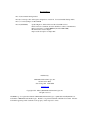
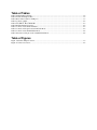
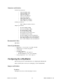
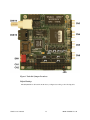
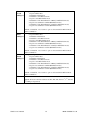
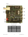
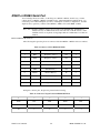
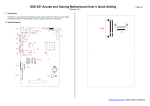
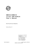
CM313HR Quad Serial & Ethernet
utilityModule™
User’s Manual
BDM-610020011
Rev. D
ISO9001 and AS9100 Certified
CM313HR
Quad Serial & Ethernet utilityModule™
User’s Manual
RTD Embedded Technologies, Inc.
103 Innovation Blvd.
State College, PA 16803-0906
Phone: +1-814-234-8087
FAX: +1-814-234-5218
E-mail
[email protected]
[email protected]
web site
http://www.rtd.com
Revision History
Rev. A) New manual naming method
Rev. B) Corrected positive and negative designations on table 10. Corrected Default Settings Table.
Rev. C) Corrected jumpers for Rev B PCB
Rev. D (05/02/2007)
Updated Figure 2, which still showed the older PCB revision.
Fixed an incorrect statement about the default base address of the Ethernet.
Removed references to CM313HRSET (should be ISMC9000).
Modernized the software chapter.
Improved the description of Jumper JP6.
Published by:
RTD Embedded Technologies, Inc.
103 Innovation Blvd.
State College, PA 16803-0906
www.rtd.com
Copyright 1999 - 2007 by RTD Embedded Technologies, Inc.
All rights reserved.
The RTD Logo is a registered trademark of RTD Embedded Technologies. cpuModule and utilityModule are
trademarks of RTD Embedded Technologies. PC/104 is a registered trademark of PC/104 Consortium. All other
trademarks appearing in this document are the property of their respective owners.
Table of Contents
CHAPTER 1
INTRODUCTION .................................................................................. 1-1
CM313HR Communications utilityModule........................................................................................................1-1
Features ................................................................................................................................................................ 1-1
Connectors and Switches ....................................................................................................................................1-2
Recommended Cables.........................................................................................................................................1-2
General Specifications ........................................................................................................................................1-2
Configuring the utilityModule............................................................................................................................ 1-2
Jumpers and Switches .........................................................................................................................................1-2
Ethernet EEPROM Configuration..................................................................................................................... 1-7
CHAPTER 2
INSTALLING THE UTILITYMODULE .................................................. 2-1
Recommended Procedure ................................................................................................................................... 2-1
Finding Pin 1 of Connectors ............................................................................................................................... 2-1
PC/104 Bus Connectors, CN1 and CN2 ............................................................................................................. 2-3
First COM port, CN3 .......................................................................................................................................... 2-4
Second COM port, CN4 ...................................................................................................................................... 2-7
Third COM port, CN5 ........................................................................................................................................ 2-7
Fourth COM port, CN6 ...................................................................................................................................... 2-7
Base Address of Common Registers...................................................................................................................2-8
Common Register definitions .............................................................................................................................2-8
10Base-T connector, CN8.................................................................................................................................. 2-10
10Base-T connector, CN10................................................................................................................................ 2-11
10Base-2 connector, CN14 ................................................................................................................................ 2-11
Power Protection Circuitry............................................................................................................................... 2-12
CHAPTER 3
USING THE UTILITYMODULE SERIAL PORTS................................. 3-1
1.5 Mbps support ................................................................................................................................................. 3-1
Interrupt Sharing ................................................................................................................................................ 3-1
CHAPTER 4
USING THE UTILITYMODULE ETHERNET PORTS .......................... 4-1
Diagnostic LEDs .................................................................................................................................................. 4-1
Boot ROM Socket ................................................................................................................................................ 4-1
Power Consumption ............................................................................................................................................ 4-2
Solder Jumpers .................................................................................................................................................... 4-2
CHAPTER 5
SOFTWARE UTILITIES ....................................................................... 5-4
The ISMC9000.EXE Program............................................................................................................................ 5-4
The 313DIAG.EXE Program.............................................................................................................................. 5-4
Ethernet Drivers .................................................................................................................................................. 5-4
Serial Port Drivers............................................................................................................................................... 5-4
CHAPTER 6
REFERENCE INFORMATION ............................................................. 6-5
Ethernet References............................................................................................................................................. 6-5
Types of Ethernet................................................................................................................................................. 6-5
Types of Ethernet cable....................................................................................................................................... 6-6
10Base-T Wiring Convention ............................................................................................................................. 6-7
Ethernet frames ................................................................................................................................................... 6-8
IEEE 802 MAC number...................................................................................................................................... 6-8
CHAPTER 7
RETURN POLICY AND WARRANTY .................................................. 7-1
Return Policy ....................................................................................................................................................... 7-1
Limited Warranty................................................................................................................................................ 7-1
Table of Tables
Table 1 Default Jumper Settings................................................................................................................................ 1-4
Table 2 Switch and Jumper tables ............................................................................................................................. 1-5
Table 3 Base address table for COM ports ................................................................................................................ 1-7
Table 4 Connector Table ........................................................................................................................................... 2-2
Table 5 PC/104 XT Bus Connector ....................................................................................................................... 2-3
Table 6 PC/104 AT Bus Connector ........................................................................................................................... 2-4
Table 7 Connector CN3 in RS-232 Mode ................................................................................................................. 2-5
Table 8 Connector CN3 pin location in RS-232 Mode.............................................................................................. 2-5
Table 9 Connector CN3 in RS422/485 Mode............................................................................................................ 2-6
Table 10 Connector CN3 pin location in RS422/485 Mode...................................................................................... 2-6
Table of Figures
Figure 1 Switch & Jumper Locations......................................................................................................................... 1-3
Figure 2 Connector Locations.................................................................................................................................... 2-2
Chapter 1 INTRODUCTION
This manual gives information on the CM313HR Communications utilityModule. This module
supports four versatile serial ports with jumper configurable IRQ lines and I/O addresses and one
10Base-T / 10Base-2 Ethernet interface for your PC/104 applications.
CM313HR Communications utilityModule
The CM313HR Communications utilityModule was designed to provide four versatile serial ports
and an Ethernet interface to support the RTD cpuModules and other standard PC/104 processor
modules.
Features
The following are major features of the CM313HR utilityModule.
Serial ports
•
•
•
•
•
•
•
•
•
•
Compatibility with the Industry Standard 16C550 UART
Up to 1.5 Mbps baud transmit/receive operation (24 MHz)
16 byte transmit FIFO/16 byte receive FIFO with error flags
Independent transmit and receive control
Standard modem interface
Jumper selectable to interrupt line, base address, RS232/RS422-485 mode per port
Jumper selectable enable/disable per port
Includes 42 different selectable I/O base addresses
Low power-consumption
Typical from single +5V power supply
Ethernet
SMC9000 compatible Ethernet controller
• SMC 91C96I chipset
• Internal 6k RAM
Multiple Ethernet interfaces
• 10Base-T UTP (unshielded twisted pair)
• 10Base-2 BNC
Software Configurable
• Jumperless configuration for I/O address, interrupt, mode
• Configuration stored in EEPROM
Boot ROM socket
• Allows remote booting of cpuModule from file server
Software Included
•
•
•
CM313 User’s Manual
Serial Port diagnostic
Ethernet configuration program
Ethernet Drivers
1-1
BDM- 610020011 rev D
Connectors and Switches
Connectors provided are:
• CN1: PC/104 Bus (XT)
• CN2: PC/104 Bus (AT)
• CN3: First COM port
• CN4: Second COM port
• CN5: Third COM port
• CN6: Fourth COM port
• CN8: 10Base-T port (RJ45)
• CN14: 10Base-2 port (BNC)
Switches provided are:
• SW1: COM ports address selection
Jumpers provided are:
•
•
•
•
•
•
•
•
•
•
JP1: First COM port IRQ
JP2: Second COM port IRQ
JP3: Third COM port IRQ
JP4: Fourth COM port IRQ
JP5: Serial port clock source select
JP6: Ethernet default settings
JP8: First COM port mode and termination
JP9: Second COM port mode and termination
JP10: Third COM port mode and termination
JP11: Fourth COM port mode and termination
Recommended Cables
XK-CM30
General Specifications
•
•
•
•
•
Dimensions: 3.8 x 3.9 x 0.6" (97 x 100 x 16 mm)
Weight (mass): 3.0 ounces (85 grams)
6-layer PCB
Operating conditions:
• Temperature: -40 - +85 degrees C
• Relative humidity: 0 - 95%, non-condensing
Storage temperature: -55 to +125 degrees C
Configuring the utilityModule
The following sections contain information on configuring the utilityModule.
Please read this entire section before attempting to use the utilityModule!
Jumpers and Switches
Locations
The figure below shows switch and jumper locations.
CM313 User’s Manual
1-2
BDM- 610020011 rev D
Figure 1 Switch & Jumper Locations
Default Settings
The utilityModule is delivered from the factory configured according to the following table.
CM313 User’s Manual
1-3
BDM- 610020011 rev D
Table 1 Default Jumper Settings
Jumper
JP1
G jumper
JP2
G jumper
JP3
G jumper
JP4
G jumper
JP5
CLK jumper
JP6
Ethernet
Config
JP8
First
COM port
JP9
Second
COM port
JP10
Third
COM port
JP11
Fourth
COM port
SW1
CM313 User’s Manual
Setting
3-4
Installed
1-2
Installed
5-6
Installed
13-14
Installed
2-3 installed
Function
IRQ4 for 1st COM port
1K pull down resister on IRQ4 line
IRQ3 for 2nd COM port
1K pull down resister on IRQ3 line
IRQ5 for 3rd COM port
1K pull down resister on IRQ5 line
IRQ10 for 4th COM port
1K pull down resister on IRQ10 line
24 MHz / 13 input clock is selected for serial ports
1-2 open
Ethernet is software-configurable
1-2 open
3-4 installed
5-6 open
7-8 open
1-2 open
3-4 installed
5-6 open
7-8 open
1-2 open
3-4 installed
5-6 open
7-8 open
1-2 open
3-4 installed
5-6 open
7-8 open
All down
Enable port
Select RS-232 mode
No termination on RxD (Not required for RS-232 mode)
No termination on CTS (Not required for RS-232 mode)
Enable port
Select RS-232 mode
No termination on RxD (Not required for RS-232 mode)
No termination on CTS (Not required for RS-232 mode)
Enable port
Select RS-232 mode
No termination on RxD (Not required for RS-232 mode)
No termination on CTS (Not required for RS-232 mode)
Enable port
Select RS-232 mode
No termination on RxD (Not required for RS-232 mode)
No termination on CTS (Not required for RS-232 mode)
I/O base addresses at
3E8, 2E8, 280, 288 for 1st, 2nd, 3rd and 4th COM port
respectively
1-4
BDM- 610020011 rev D
Descriptions
The following table describes the functions of the jumpers.
Table 2 Switch and Jumper tables
Jumper
JP 1
JP 2
JP3
JP 4
JP5
JP6
Use
IRQ selection for COM1
G setting: jumper installed = 1K pull down resistor for the selected IRQ
Jumper removed = no pull down for the selected IRQ
Default: 3-4, IRQ4 is selected for CN3 with G jumper installed (1K pull-down)
IRQ selection for COM2
G setting: jumper installed = 1K pull down resistor for the selected IRQ
Jumper removed = no pull down for the selected IRQ
Default: 1-2, IRQ3 is selected for CN4 with G jumper installed (1K pull-down)
IRQ selection for COM3
G setting: jumper installed = 1K pull down resistor for the selected IRQ
Jumper removed = no pull down for the selected IRQ
Default: 5-6, IRQ5 is selected for CN5 with G jumper installed (1K pull-down)
IRQ selection for COM4
G setting: jumper installed = 1K pull down resistor for the selected IRQ
Jumper removed = no pull down for the selected IRQ
Default: 13-14, IRQ10 is selected for CN6
With G jumper installed (1K pull-down)
Input clock selection for serial ports
1-2 = select 24 MHz input clock to UART
2-3 = select 24 MHz / 13 input clock to UART
Default: 2-3 jumped, to select 1.8432 MHz to UART
Ethernet Configuration Selection
1-2 installed = Factory default configuration for Ethernet
1-2 open = Software programmable configuration
(Use ISMC9000 to set configuration.)
Default: 1-2 open to enable software programmable configuration
COM port configuration
JP8
First
1-2 open = Enable Port
COM port
1-2 installed = Disable Port
3-4 installed = select RS-232 mode
3-4 open = select RS-422/485 mode
5-6 installed = 120 ohm termination on RxD (for RS422/485 modes)
5-6 open = No termination on RxD (RS422/485 modes)
7-8 installed = 120 ohm termination on CTS (for RS422/485 modes)
7-8 open = No termination on CTS (RS422/485 modes)
Default: 3-4 installed, 1-2, 5-6 and 7-8 open to select enabled for RS-232 mode
with no termination
CM313 User’s Manual
1-5
BDM- 610020011 rev D
COM port configuration
JP9
Second
1-2 open = Enable Port
COM port
1-2 installed = Disable Port
3-4 installed = select RS-232 mode
3-4 open = select RS-422/485 mode
5-6 installed = 120 ohm termination on RxD (for RS422/485 modes)
5-6 open = No termination on RxD (RS422/485 modes)
7-8 installed = 120 ohm termination on CTS (for RS422/485 modes)
7-8 open = No termination on CTS (RS422/485 modes)
Default: 3-4 installed, 1-2, 5-6 and 7-8 open to select enabled for RS-232 mode
with no termination
COM port configuration
JP10
Third
1-2 open = Enable Port
COM port
1-2 installed = Disable Port
3-4 installed = select RS-232 mode
3-4 open = select RS-422/485 mode
5-6 installed = 120 ohm termination on RxD (for RS422/485 modes)
5-6 open = No termination on RxD (RS422/485 modes)
7-8 installed = 120 ohm termination on CTS (for RS422/485 modes)
7-8 open = No termination on CTS (RS422/485 modes)
Default: 3-4 installed, 1-2, 5-6 and 7-8 open to select enabled for RS-232 mode
with no termination
COM port configuration
JP11
Fourth
1-2 open = Enable Port
COM port
1-2 installed = Disable Port
3-4 installed = select RS-232 mode
3-4 open = select RS-422/485 mode
5-6 installed = 120 ohm termination on RxD (for RS422/485 modes)
5-6 open = No termination on RxD (RS422/485 modes)
7-8 installed = 120 ohm termination on CTS (for RS422/485 modes)
7-8 open = No termination on CTS (RS422/485 modes)
SW1
Default: 3-4 installed, 1-2, 5-6 and 7-8 open to select enabled for RS-232 mode
with no termination
I/O base address switch. See Base Address Table for details
Default: All down = I/O base addresses at 3E8, 2E8, 280, 288 for 1st, 2nd, 3rd and
4th COM port respectively
CM313 User’s Manual
1-6
BDM- 610020011 rev D
Table 3 Base address table for COM ports
COM port addresses –base address in Hex for eight 8-bit registers
SW1-4
SW-3
SW-2
SW-1
CN3
CN4
CN5
CN6
Down
Down
Down
Down
3E8
2E8
280
288
Down
Down
Down
Up
280
288
290
298
Down
Down
Up
Down
290
298
2A0
2A8
Down
Down
Up
Up
2A0
2A8
2B0
2B8
Down
Up
Down
Down
100
108
110
118
Down
Up
Down
Up
120
128
130
138
Down
Up
Up
Down
140
148
150
158
Down
Up
Up
Up
160
168
170
178
Up
Down
Down
Down
100
108
500
508
Up
Down
Down
Up
120
128
520
528
Up
Down
Up
Down
280
288
680
688
Up
Down
Up
Up
290
298
690
698
Up
Up
Down
Down
2E8
2A8
6E8
6A8
Up
Up
Down
Up
2F8
3E8
2E8
6E8
Up
Up
Up
Down
3E8
2E8
7E8
6E8
Up
Up
Up
Up
3F8
2F8
3E8
2E8
Ethernet EEPROM Configuration
The most important configuration options for the Ethernet section are set using the configuration
program ISMC9000.EXE, and then stored in a configuration EEPROM.
ISMC9000 is used to select:
•
•
•
•
I/O Address
Hardware interrupt number
Media Type
Boot PROM Address
CM313 User’s Manual
1-7
BDM- 610020011 rev D
Default Settings
The factory default settings for ISMC9000 options are:
Option
I/O address
Interrupt
Media type
Boot PROM
Factory Default
300h
IRQ2/9
Auto
Disabled
Please refer to page 5-4 for information on changing these settings using ISMC9000.EXE.
CM313 User’s Manual
1-8
BDM- 610020011 rev D
Chapter 2 INSTALLING THE UTILITYMODULE
Since the utilityModule uses a PC/104 stackthrough bus, the only hardware installation you will do
is placing the module to the PC/104 stack. To do this, you will connect the PC/104 bus connector
with the matching connector of another module.
Recommended Procedure
We recommend you follow the procedure below to ensure that stacking of the modules does not
damage connectors or electronics.
•
•
•
•
•
•
•
•
Turn off power to the PC/104 system or stack.
Select and install standoffs to properly position the utilityModule on the PC/104 stack.
Touch a grounded metal part of the stack to discharge any buildup of static electricity.
Remove the utilityModule from its anti-static bag.
Check that keying pins in the PC/104 bus connector are properly positioned.
Check the stacking order: make sure an XT bus card will not be placed between two AT bus
cards, or it will interrupt the AT bus signals.
Hold the utilityModule by its edges and orient it so the bus connector pins line up with the
matching connector on the stack.
Gently and evenly press the utilityModule onto the PC/104 stack.
CAUTION: Do not force the module onto the stack! Wiggling the module or applying too much
force may damage it. If the module does not readily press into place, remove it, check
for bent pins or out-of-place keying pins, and try again.
Connecting the utilityModule
The following sections describe connectors of the utilityModule.
Finding Pin 1 of Connectors
A white area silk-screened on the PC board indicates pin 1 of connectors. A square solder pad
visible on the bottom of the PC board also indicates it.
CM313 User’s Manual
2-1
BDM- 610020011 rev D
Locations
The figure below shows connector locations.
Figure 2 Connector Locations
Table 4 Connector Table
Connector
CN1
CN2
CN3
CN4
CN5
CN6
CN8
CN10
CN14
CM313 User’s Manual
Function
PC/104 XT Bus
PC/104 AT Bus
1st COM port
2nd COM port
3rd COM port
4th COM port
10Base-T
10Base-T
10Base-2
2-2
Size
64 pin
40 pin
10 pin
10 pin
10 pin
10 pin
RJ45
10 pin
BNC
BDM- 610020011 rev D
PC/104 Bus Connectors, CN1 and CN2
Connectors CN1 and CN2 provide PC/104 bus connections. CN1 carries XT bus signals, and CN2
carries additional signals for the AT bus. The signals on CN1 and CN2 conform to the IEEE P966
standard for the PC/104 bus.
The following tables list the connector pinouts:
Table 5 PC/104 XT Bus Connector
Pin
1
2
3
4
5
6
7
8
9
10
11
12
13
14
15
16
17
18
19
20
21
22
23
24
25
26
27
28
29
30
31
32
CM313 User’s Manual
PC/104 XT Bus Connector, CN1
Row A
Row B
IOCHCHK*
SD7
SD6
SD5
SD4
SD3
SD2
SD1
SD0
IOCHRDY
AEN
SA19
SA18
SA17
SA16
SA15
SA14
SA13
SA12
SA11
SA10
SA9
SA8
SA7
SA6
SA5
SA4
SA3
SA2
SA1
SA0
0V
2-3
0V
RESETDRV
+5V
IRQ9
-5V
DRQ2
-12V
ENDXFR*
+12V
(KEYING PIN)
SMEMW*
SMEMR*
IOW*
IOR*
DACK3
DRQ3
DACK1*
DRQ1
REFRESH
SYSCLK
IRQ7
IRQ6
IRQ5
IRQ4
IRQ3
DACK2*
TC
BALE
+5V
OSC
0V
0V
BDM- 610020011 rev D
Table 6 PC/104 AT Bus Connector
Pin
0
1
2
3
4
5
6
7
8
9
10
11
12
13
14
15
16
17
18
19
Note:
PC/104 AT Bus Connector, CN2
Row C
Row D
0V
SBHE*
LA23
LA22
LA21
LA20
LA19
LA18
LA17
MEMR*
MEMW*
SD8
SD9
SD10
SD11
SD12
SD13
SD14
SD15
(KEYING PIN)
0V
MEMCS16*
IOCS16*
IRQ10
IRQ11
IRQ12
IRQ15
IRQ14
DACK0*
DRQ0
DACK5*
DRQ5
DACK6*
DRQ6
DRQ6
DRQ7
+5V
MASTER*
0V
0V
Two locations on the bus have mechanical keying pins to help prevent misconnection
of the PC/104 bus. These keying pins are a part of the PC/104 standard, and we
strongly recommend you leave them in place.
If you have other modules without keying pins, we suggest you modify them to
include keying.
First COM port, CN3
The first serial port is implemented on connector CN3. It can be configured as a PC compatible
full duplex RS232 port or as half- or full duplex RS422 or RS485 through mode jumper JP8. The
I/O address is configurable in respect to SW1 address table, and corresponding interrupt is also
selectable through jumper JP1 to be IRQ3, IRQ4, IRQ5, IR6, IRQ7, IRQ9, IRQ10, IRQ11, IRQ12,
IRQ14 and IRQ15. But you need to make sure that there are no resource conflicts on the I/O base
address and interrupt line you choose.
The serial port is implemented with a 16C550-compatible UART (Universal Asynchronous
Receiver/Transmitter). This UART is capable of baud rates up to 1.5 M with the 24 MHz clock
input and 115.2K with the 24 MHz / 13 clock input.
CM313 User’s Manual
2-4
BDM- 610020011 rev D
RS232 Serial Port (Default)
The full-duplex RS232 mode is the default setting on the utilityModule. With this mode enabled,
connector CN3 must be connected to RS232 compatible devices. The following table gives the
connector pinout and shows how to connect to an external serial connector, either DB25 or DB9
compatible.
Connector CN3 in RS-232 Mode
Table 7 Connector CN3 in RS-232 Mode
CN3 Pin
Signal
Function
In/out
DB25
DB9
1
DCD
Data Carrier Detect
In
8
1
2
DSR
Data Set Ready
In
6
6
3
RXD
Receive Data
In
3
2
4
RTS
Request To Send
Out
4
7
5
TXD
Transmit Data
Out
2
3
6
CTS
Clear To Send
In
5
8
7
DTR
Data Terminal Ready
Out
20
4
8
RI
Ring Indicate
In
22
9
9,10
GND
Signal Ground
--
7
5
Facing the connector pins, the pinout is pictured in the following,
Table 8 Connector CN3 pin location in RS-232 Mode
9
7
5
3
1
GND
DTR
TXD
RXD
DCD
GND
RI
CTS
RTS
DSR
10
8
6
4
2
CM313 User’s Manual
2-5
BDM- 610020011 rev D
RS422 or RS485 Serial Port
You can change the mode switch to set the first port as RS422 or RS485. In this case, you must
connect CN3 to an RS422 or RS485 compatible device. When using RS422 or RS485 mode, you
can use the port in either half-duplex (two-wire) or full-duplex (four-wire) configurations. For halfduplex (2-wire) operation, you must connect RXD+ to TDX+, and connect RXD- to TXD-.
Note! Two 120-ohm termination resistors are provided on the utilityModule. Termination is
usually necessary on all RS-422 receivers and at the ends of the RS-485 bus. If the
termination resistor is required, closing jumper JP8 5-6 for RxD and/or 7-8 CTS can
enable it.
RS422 and RS485 Mode Pinout
The following table gives the pinout of connector CN3 when RS422 or RS485 modes are enabled.
Table 9 Connector CN3 in RS422/485 Mode
CN3 Pin
Signal
Function
In/out
DB9
1
RTS-
Request to send (-)
Out
1
2
RTS+
Request to send (+)
Out
6
3
RXD-
Receive Data (-)
In
2
4
TXD+
Transmit Data (+)
Out
7
5
TXD-
Transmit Data (-)
Out
3
6
RXD+
Receive Data (+)
In
8
7
CTS-
Clear to send (-)
In
4
8
CTS+
Clear to send (+)
In
9
9,10
GND
Signal Ground
--
5
Facing the connector pins, the pinout is pictured in the following,
Table 10 Connector CN3 pin location in RS422/485 Mode
9
7
5
3
1
GND
CTS-
TXD-
RXD-
RTS-
GND
CTS+
RXD+
TXD+
RTS+
10
8
6
4
2
CM313 User’s Manual
2-6
BDM- 610020011 rev D
Notes on using RS422 or RS485 Modes
When using the serial port in RS422 or RS485 mode, the serial receiver is always enabled,
however the serial transmitter is enabled and disabled under software control in the following two ways.
By default, the transmitter is enabled by manipulating the Request To Send (RTS*) signal of the
serial port controller. Writing bit 1 of the Modem Control Register (MCR) as follows controls this signal:
- If MCR bit 1 = 1, then RTS* = 0, and serial transmitter is disabled
- If MCR bit 1 = 0, then RTS* = 1, and serial transmitter is enabled
The other way to enable the serial transmitter is to write 1 to its corresponding bit of the
utilityModule’s internal common register 4, which sets the serial transmitter in “always on” mode. Please
refer to Internal Common Register Section for detail.
The drivers are disabled in RS-422/485 mode at power up. You must enable the drivers by writing
a 1 to the driver enable bit of the utilityModule’s internal common register 4. Please refer to Internal
Common Register Section for detail.
Second COM port, CN4
Please refer to the previous section on the first COM port CN3 for the description on CN4.
Third COM port, CN5
Please refer to the previous section on the first COM port CN3 for the description on CN5.
Fourth COM port, CN6
Please refer to the previous section on the first COM port CN3 for the description on CN6.
CM313 User’s Manual
2-7
BDM- 610020011 rev D
CM313HR common registers
The utilityModule includes 5 common registers to provide additional information and software
control that is not required for normal COM port operation, but may be helpful in determining the
status of the board and configuring of the board. The following two sections give the location and
definition of the common registers.
Base Address of Common Registers
The utilityModule common registers are located 800h above the address of the first enabled COM
port. That is, assuming that “X” in hex is the first enabled COM port base address, which can be
any of the valid addresses listed in the Com Port Address Table, the base address for the common
registers is “Y” in hex, then,
Y = X + 800h
For example, if the switches of SW4 are set all DOWN position which makes CN3 = 3E8h, CN4 =
2E8h, CN5 = 280h and CN6 = 288h, then according to the algorithm, the common registers base
address (BA) will be the following depending the setting of enable switch SW2 for each serial
port,
If CN3 is enabled then,
BA = 3E8h + 800h = BE8h
Else if CN3 is disabled AND CN4 is enabled then,
BA = 2E8h + 800h = AE8h
Else if CN3 and CN4 are disabled AND CN5 is enabled then,
BA = 280h + 800h = A80h
Else if CN3, CN4 and CN5 are disabled AND CN4 is enabled then,
BA = 288h + 800h = A88 A80h
Else if CN3, CN4, CN5 and CN6 are disabled then,
Common Registers are disabled
End If
Common Register definitions
BA + 0 – Interrupt Status (Read Only)
7
6
5
4
3
2
Reserved
Reserved
TxRDY*
RxRDY*
CN6
CN5
For each CNx bit:
0 = Not interrupting
1 = Interrupt set
TxRDY*
CM313 User’s Manual
2-8
1
CN4
0
CN3
BDM- 610020011 rev D
0 = indicates a buffer ready for at least one of the four transmit channels
1 = indicates that all transmit buffers are full
RxRDY*
0 = indicates one or more of the receive channels has data ready to read
1 = indicates that all receive buffers are empty
Reserved reads as 0
BA + 1 – Address Switch (Read Only)
7
6
5
4
3
2
Reserved
Reserved
Reserved
Reserved
SW1-4
SW1-3
For each bit, see table above
0 = Down
1 = Up
Reserved reads as A to tag on the address register.
BA + 2 -- Enable/Disable Jumpers (Read Only)
7
6
5
4
3
2
Reserved
Reserved
Reserved
Reserved
CN6
CN5
For each CNx bit:
Jumper installed = 0 = Port is disabled
Jumper open = 1 = Port is enabled
Reserved reads as 0
7
6
Reserved
Reserved
Reserved reads as 0
7
Reserved
6
Reserved
5
Reserved
BA + 3—Reserved
4
3
Reserved
Reserved
2
Reserved
BA + 4-- RS-422 RTS operation (W)
5
4
3
2
Driver
IntSel
CN6
CN5
Enable
1
SW1-2
0
SW1-1
1
CN4
0
CN3
1
Reserved
0
Reserved
1
CN4
0
CN3
Driver Enable:
0 = All ports in RS-422/485 mode will have the drivers disabled
1 = All ports in RS-422/485 mode will have the drivers controlled as selected in register 4 and 5
Default to 0 to have drivers disabled during power up. User must program to a 1 to use RS-422/485 mode.
IntSel:
0 = MCR bit-3 controls the three state interrupt output.
1 = Overrides MCR bit-3 and interrupt outputs are enabled continuously.
Default to 0 to set COM ports in normal mode
For each CNx bit:
0 = use RTS to enable transmitter, default case
1 = transmitter always on
BA + 5-- RS-422 TxD operation (W)
7
6
5
4
3
2
1
TxD+/-CN6 TxD+/-CN5 TxD+/-CN4 TxD+/-CN3
CN6
CN5
CN4
For each CNx bit:
0 = use RTS to enable transmitter or transmitter always on as defined by BA + 4 register CNx bit
1 = Use TxD to enable transmitter, transmitter data is tied low
CM313 User’s Manual
2-9
0
CN3
BDM- 610020011 rev D
For each TxD+/-CNx bit if corresponding CNx bit is 1:
0 = Use TxD to enable transmitter
1 = Use inverted TxD to enable transmitter
+5V
1
REG4[3:0]
BIT PER
CHANNEL
0
0
1
RTS
TxD
1
REG4[5]
ALL
CHANNELS
Enable
0
TxD+
0
1
TxD-
1
REG5[7:4]
BIT PER
CHANNEL
0
REG5[3:0]
BIT PER
CHANNEL
RS-422/485 Driver
RS-422/485 mode configuration. All switches are shown in power on default conditions.
10Base-T connector, CN8
Connector CN8 is for UTP (Unshielded Twisted Pair) wiring normally used for 10Base-T
Ethernet. It is wired in parallel with CN10. Don't try to use both CN8 and CN10 at the same time.
The following table gives the pinout of CN8.
Pin
1
2
3
4
5
6
7
8
Signal
TX+
TXRX+
N.C.
N.C.
RXN.C.
N.C.
Function
Transmit +
Transmit Receive +
not connected
not connected
Receive not connected
not connected
in/out
out
out
in
in
The figure below shows the pin numbering of CN8 when looking into the connector:
CM313 User’s Manual
2-10
BDM- 610020011 rev D
1 2 3 4 5 6 7 8
RJ-45 Jack Connector
CN8 is a standard female RJ-45 connector. One example of a mating plug is:
•
AMP 5-554739-3 (unshielded)
10Base-T connector, CN10
Connector CN10 is for UTP (Unshielded Twisted Pair) wiring normally used for 10Base-T
Ethernet. It is wired in parallel with CN8. Don't try to use both CN8 and CN10 at the same time.
The following table gives the pinout of CN10.
Pin
1
2
3
5
4, 6 - 10
Signal
TX+
RXTXRX+
N.C.
Function
Transmit +
Receive Transmit Receive +
not connected
in/out
out
in
out
in
10Base-2 connector, CN14
Connector CN14 is a BNC bayonet connector for coaxial cable normally used with 10Base-2
Ethernet.
The pinout of CN14 is:
Pin
1
2
Signal
SIGNAL
GND
Function
Signal to 50 ohm cable
Signal Ground
in/out
in/out
--
BNC Connector CN14
CM313 User’s Manual
2-11
BDM- 610020011 rev D
Power Protection Circuitry
To reduce the risk of damage due to power-supply problems, the utilityModule includes several
protective components.
Module Power-Supply Protection
The utilityModule includes a component to help prevent damage due to problems with the +5Vdc
power supply from the PC/104 bus. Protection is provided for:
• Over-current
• Reversed polarity
• Excessive voltage
This protection is only for the utilityModule, and will not protect other devices in a PC/104 stack.
The protective fuse is replaceable and is available from electronics suppliers. Its description and
part number is:
Littelfuse Nano2 SMF 1.0 amp, R451-001
Caution:
CM313 User’s Manual
Replace fuses only with parts of identical current and voltage rating.
2-12
BDM- 610020011 rev D
Chapter 3 USING THE UTILITYMODULE
SERIAL PORTS
The utilityModule features an EXAR quad UART 16C550 compatible 16C554D part.
EXAR Documentation
Due to the complexity of the EXAR serial chip, it is impossible for us to reproduce all
programming information in this manual. If you will be doing in-depth programming of the serial
port controller, we suggest you obtain the 16C554D datasheet from the manufacturer.
The 16C554D datasheet is available on-line in electronic format as an Adobe Acrobat (. PDF) file
on the EXAR website:
www.exar.com
1.5 Mbps support
With 24 MHz clock input selected (JP5, 1-2), the utilityModule is capable of provide data rates up
to 1.5 Mbps in RS422/RS485 mode. The RS-232 buffers restrict the data rate to 120 Kbps in RS232 mode.
Interrupt Sharing
Interrupt sharing is a mechanism which allows different devices sharing same active high IRQ lines
on the PC/104 bus, given that there is a interrupt sharing circuit associated with each device. The
utilityModule provides interrupt-sharing circuits for all the serial ports; thus it allows sharing of
one IRQ line among the serial ports in the utilityModule. However, user needs to be careful to
share an IRQ line with devices in the system elsewhere, and be sure that other devices also share
their IRQ lines as well. For instance, users should be aware of that the IRQ3/IRQ4 associated with
serial port J3/J4 on RTDUSA cpuModule are not shareable. And if the utilityModule is in the
same system with RTDUSA cpuModule, be advised not to use/share IRQ3/IRQ4 for the
utilityModule unless you have serial ports on the cpuModule disabled.
Interrupt sharing in a PC/104 system requires one 1K pull-down resistor per IRQ line for all the
devices that share the IRQ. Installing a G jumper in the utilityModule will pull its associated IRQ
line down with a 1K resistor. That is, for example, if IRQn is shared among four serial ports on
the utilityModule, only one G jumper needs to be installed for IRQn line. If more than one G
jumper are installed, the pull-down on IRQn line will be much stronger that expected 1K-ohm,
which will prevent interrupt controller from functioning correctly.
Let consider two cases to demonstrate the concepts for the above discussion. Let us assume that
IRQ5 and IRQ10 are not used and driven by other devices in the system. For the first case, IRQ10
line is shared among the four serial ports and for the second case IRQ5 is shared for port 1 and
port 2, while IRQ10 is shared among port 3 and port 4.
The following two tables listed the interrupt jumper settings for each case respectively.
CM313 User’s Manual
3-1
BDM- 610020011 rev D
Table 11 Jumper Settings for interrupt sharing Case 1
Jumper
JP1
G jumper
Setting
13-14
Installed
JP2
G jumper
13-14
Removed
JP3
G jumper
13-14
Removed
JP4
G jumper
13-14
Removed
Function
IRQ10 for 1st COM port
1K pull down resister added on IRQ10
from PORT1
IRQ10 for 2nd COM port
No pull down resister added on IRQ10
from PORT2
IRQ10 for 3rd COM port
No pull down resister added on IRQ10
from PORT3
IRQ10 for 4th COM port
No pull down resister added on IRQ10
from PORT4
Table 12 Jumper Settings for interrupt sharing Case 2
CM313 User’s Manual
Jumper
JP1
G jumper
Setting
5-6
Installed
JP2
G jumper
5-6
Removed
JP3
G jumper
13-14
Installed
JP4
G jumper
13-14
Removed
Function
IRQ5 for 1st COM port
1K pull down resister added on IRQ5
from PORT1
IRQ5 for 2nd COM port
No pull down resister added on IRQ5
from PORT2
IRQ10 for 3rd COM port
1K pull down resister added on IRQ10
from PORT3
IRQ10 for 4th COM port
No pull down resister added on IRQ10
from PORT4
3-2
BDM- 610020011 rev D
Chapter 4 USING THE UTILITYMODULE
ETHERNET PORTS
Using the utilityModule is straightforward, and essentially identical to any other Ethernet card.
When CM313HR module is powered on, data in the EEPROM on board is transferred to Ethernet
controller’s internal configuration registers. The data in the EEPROM contains information
configuration such as the base address of the card, the active interrupt line on the PC/104 bus for
Ethernet access, the media type in use, etc. The factory default setting of the board is at I/O
address 0x300 and IRQ 2/9. And if there is a resource conflicting, you need to change your setting
on CM313HR with the other I/O boards removed temporally by executing ISMC9000 program as
described in a later chapter.
The following sections describe:
•
•
•
Diagnostic LEDs
Boot ROM socket
Power Consumption
Diagnostic LEDs
CN8, the RJ45 connector, has two LEDs that are used to indicate status and provide some
diagnostic information in case of malfunctions.
Name
TX/RX
LNK
Meaning
Transmit or Receive data
Link established (UTP)
Normal State
Flashing with traffic
On (10Base-T only)
TX/RX LED
The yellow LED normally flashes when there is traffic on the network. It will flash for either
transmit or receive data.
LNK LED
The green LED is turned on when a valid 10Base-T link is detected by the chipset. It is only active
when using the 10Base-T UTP connection with link integrity checking enabled. If it is off, the
UTP wiring may be broken or incorrect, link integrity checking may be disabled, or you may be
using the 10Base-2 or AUI interface.
Boot ROM Socket
In some applications, you may wish to use the boot ROM socket of the utilityModule to boot a
connected cpuModule from a remote server.
The socket will accommodate a 32 pin PLCC EPROM or Flash memory devices of size 8k, 16k,
32k, or 64k bytes. The device must be a byte-wide architecture.
The boot ROM feature can be enabled using the ISMC9000 program described on page 5-4.
CM313 User’s Manual
4-1
BDM- 610020011 rev D
Power Consumption
Power consumption of the utilityModule depends on which Ethernet interface is used and the
degree of activity on the network.
The following table gives typical power consumption:
Configuration
Consumption
AUI
200 mA
TP
200 mA
BNC
200 mA
Solder Jumpers
The CM113HR has solder jumpers to configure the system. The table below gives the details.
CM313 User’s Manual
4-2
BDM- 610020011 rev D
The following table gives the solder jumper functions:
Jumper
B1
Default Setting
Open
B2
Open
B3
B3 – B10
Open
9
CM313 User’s Manual
Function
Short will connect isolated 10Base-2 ground to
chassis ground at mounting hole
Short will connect isolated 10Base-2 ground to
board ground
Line-side center tap bypass to chassis ground
Sets the IRQ that is used when IRQ 2 is selected
in the setup software. One and only one of these
solder jumpers should be shorted.
4-3
BDM- 610020011 rev D
Chapter 5 SOFTWARE
UTILITIES
The ISMC9000.EXE Program
The CM313’s Ethernet interface is completely software configurable, through jumper JP6, with all
its configuration data stored in an EEPROM. ISMC9000.EXE is a utility program supplied with
the board that allows one to view or change the existing settings of the board.
When you run the ISMC9000.EXE program, the utility looks at all possible I/O addresses. If no
module is found or if there is a conflict, the utility quits with a message. When the module is
found and correctly operating, the utility displays a menu of options.
To program a software configuration, turn off power, remove JP6, apply power, run
ISMC9000.EXE, choose Modify Configuration. Use the arrow keys to select the option you want
to change. Next, press ENTER and choose the values you require. After a reboot and running
ISMC9000.EXE the new settings should be visible by choosing Display Configuration.
To use or view hardware default settings turn off power and install JP6, and apply power. If one
wishes to view the default settings run ISMC9000.EXE and choose Display Configuration. If one
wishes to use the default settings, leave JP6 installed.
The 313DIAG.EXE Program
The supplied software package for the CM313 contains the serial diagnostic utility
313DIAG.EXE. This menu driven DOS utility will enable you to test the serial ports using
internal and external loop back and confirm the operation.
Ethernet Drivers
The companion CD that comes with the board also includes Ethernet drivers for serveral popular
operating systems (DOS, Windows, Linux). For more information on installing and using those
drivers, refer to the documentatino included with them.
Serial Port Drivers
Since the CM313 uses an industry-standard 16C550 UART, the serial ports operate like a standard
PC serial port. Even in RS-422/485 mode, their register interface is identical to that of a standard
PC serial port.
Since they operate like standard PC hardware, they should be natively supported by all modern
operating systems. No special drivers or software should be necessary.
Note that before the serial ports may be used, it may be necessary to install/configure them.
Consult your operating system’s documentation for more information on how to do this.
CM313 User’s Manual
5-4
BDM- 610020011 rev D
Chapter 6 REFERENCE INFORMATION
This chapter contains reference information concerning:
•
•
•
•
•
Ethernet References
Types of Ethernet
Types of Ethernet Cable
Ethernet Frames
IEEE 802 MAC Number
Ethernet References
To learn more about Ethernet, you might start with:
Charles Spurgeon’s Ethernet Website:
http:wwwhost.ots.utexas.edu/ethernet/ethernet-home.html
This site provides thorough overviews of 10 Mbps and faster Ethernet.
Types of Ethernet
There are three standard types of 10 Megabit Ethernet, of which 10Base-T is by far the most
common, and 10Base-5 is by far the least common.
CM313 User’s Manual
Ethernet
Type
Nickname
Data transfer
rate
Topology
Cable type
10Base-T
“Cheapernet”
10 Mbps
Star
10Base-2
“Thin” Ethernet
10 Mbps
Bus
100 ohm UTP
(unshielded
twisted pair)
RG-58 coaxial
10Base-5
“Thick”
Ethernet
10 Mbps
Bus
RG-11 coaxial
6-5
Maximum
Segment
length
100 m
328 ft
185 m
607 ft
500 m
1640 ft
BDM- 610020011 rev D
Types of Ethernet cable
Ethernet uses one of three standard cable types:
Ethernet
Type
10Base-T
10Base-2
10Base-5
Cable type
Impedance
Denomination
UTP
RG-58
RG-11
100 Ohm
50 Ohm
50 Ohm
unshielded twisted pair
Ethernet thin
Ethernet thick (yellow
cable)
Note: Although 8-conductor telephone wire is commonly used for 10Base-T connections, this type
wire is not the correct 100-ohm UTP, as it does not use twisted-pairs. Using such wire may cause
excessive crosstalk, resulting in a large number of collisions and poor network performance.
CM313 User’s Manual
6-6
BDM- 610020011 rev D
10Base-T Wiring Convention
10Base-T Ethernet uses the following wiring convention when connecting a node to a hub. It is
suggested you use this convention for consistency:
RJ45 PIN
1
2
3
4
5
6
7
8
Note:
CM313 User’s Manual
First End
Pair No.
wire color
3
3
2
1
1
2
4
4
W-G
G
W-O
BL
W-BL
O
W-BR
BR
Second End
Pair No. wire color
to
to
to
to
to
to
to
to
2
2
3
1
1
3
4
4
W-O
O
W-G
BL
W-BL
G
W-BR
BR
RJ45
PIN
1
2
3
4
5
6
7
8
W-G = White-Green
G
= Green
W-O = White-Orange
O
= Orange
W-BL = White-Blue
BL
= Blue
W-BR = White-Brown
BR
= Brown
6-7
BDM- 610020011 rev D
Ethernet frames
The following are standard Ethernet frames.
•
•
•
•
ETHERNET_II
ETHERNET_802.3
ETHERNET_802.2
ETHERNET_SNAP
Primarily used by TPC/IP
Default frame for Netware 3.11
Default frame for Netware 3.12 and 4.x
Primarily used by Appletalk
IEEE 802 MAC number
The CM202 utilityModule is identified with an Organizationally Unique Identifier (OUI) and
company_id number:
00-D0-81
The MAC (Media Access Control) number of the utilityModule is thus:
00-D0-81-xx-xx-xx
where the last three bytes are the serial number of the board, unique for each adapter.
CM313 User’s Manual
6-8
BDM- 610020011 rev D
How to Obtain Technical Support
Please assemble the following information:
utilityModule model, and serial number
list of all boards in system
list of settings from ISMC9000.EXE Setup program
description of problem
circumstances under which problem occurs
Then contact factory technical support:
Phone:
814 234-8087
E-mail:
[email protected]
Web:
http://www.rtd.com
CM313 User’s Manual
6-9
BDM- 610020011 rev D
Chapter 7 RETURN
POLICY AND WARRANTY
Return Policy
If the utilityModule requires repair, you may return it to us by following the procedure listed
below:
Caution:
Failure to follow this return procedure will almost always delay repair! Please help us
expedite your repair by following this procedure.
1) Read the Limited Warranty that follows.
2) Contact the factory and request a Returned Merchandise Authorization (RMA) number.
3) Follow the instructions provided by the RMA department.
Limited Warranty
RTD Embedded Technologies, Inc. warrants the hardware and software products it manufactures and
produces to be free from defects in materials and workmanship for one year following the date of shipment
from RTD Embedded Technologies, INC. This warranty is limited to the original purchaser of product and
is not transferable.
During the one year warranty period, RTD Embedded Technologies will repair or replace, at its option, any
defective products or parts at no additional charge, provided that the product is returned, shipping prepaid,
to RTD Embedded Technologies. All replaced parts and products become the property of RTD Embedded
Technologies. Before returning any product for repair, customers are required to contact the factory for an
RMA number.
THIS LIMITED WARRANTY DOES NOT EXTEND TO ANY PRODUCTS WHICH HAVE BEEN
DAMAGED AS A RESULT OF ACCIDENT, MISUSE, ABUSE (such as: use of incorrect input voltages,
improper or insufficient ventilation, failure to follow the operating instructions that are provided by RTD
Embedded Technologies, "acts of God" or other contingencies beyond the control of RTD Embedded
Technologies), OR AS A RESULT OF SERVICE OR MODIFICATION BY ANYONE OTHER THAN
RTD Embedded Technologies. EXCEPT AS EXPRESSLY SET FORTH ABOVE, NO OTHER
WARRANTIES ARE EXPRESSED OR IMPLIED, INCLUDING, BUT NOT LIMITED TO, ANY
IMPLIED WARRANTIES OF MERCHANTABILITY AND FITNESS FOR A PARTICULAR
PURPOSE, AND RTD Embedded Technologies EXPRESSLY DISCLAIMS ALL WARRANTIES NOT
STATED HEREIN. ALL IMPLIED WARRANTIES, INCLUDING IMPLIED WARRANTIES FOR
MECHANTABILITY AND FITNESS FOR A PARTICULAR PURPOSE, ARE LIMITED TO THE
DURATION OF THIS WARRANTY. IN THE EVENT THE PRODUCT IS NOT FREE FROM
DEFECTS AS WARRANTED ABOVE, THE PURCHASER'S SOLE REMEDY SHALL BE REPAIR OR
REPLACEMENT AS PROVIDED ABOVE. UNDER NO CIRCUMSTANCES WILL RTD Embedded
Technologies BE LIABLE TO THE PURCHASER OR ANY USER FOR ANY DAMAGES,
INCLUDING ANY INCIDENTAL OR CONSEQUENTIAL DAMAGES, EXPENSES, LOST PROFITS,
LOST SAVINGS, OR OTHER DAMAGES ARISING OUT OF THE USE OR INABILITY TO USE THE
PRODUCT.
CM313 User’s Manual
7-1
BDM- 610020011 rev D
SOME STATES DO NOT ALLOW THE EXCLUSION OR LIMITATION OF INCIDENTAL OR
CONSEQUENTIAL DAMAGES FOR CONSUMER PRODUCTS, AND SOME STATES DO NOT
ALLOW LIMITATIONS ON HOW LONG AN IMPLIED WARRANTY LASTS, SO THE ABOVE
LIMITATIONS OR EXCLUSIONS MAY NOT APPLY TO YOU.
THIS WARRANTY GIVES YOU SPECIFIC LEGAL RIGHTS, AND YOU MAY ALSO HAVE OTHER
RIGHTS WHICH VARY FROM STATE TO STATE.
CM313 User’s Manual
7-2
BDM- 610020011 rev D
RTD Embedded Technologies, Inc.
103 Innovation Blvd.
State College PA 16803-0906
USA
Our website: www.rtd.com