
1
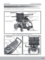
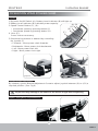
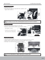
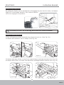
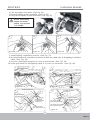
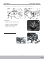
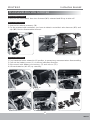
www.drivemedical.co.uk
MULTEGO
Instruction Booklet
Table of Contents
Introduction.........................................................................1
Important Precautions..........................................................2
Electromagnetic Interference and Warnings..........................3
Identification Of Parts..........................................................5
Operating Your Power Chair.....................................................6
Disassembling Your Power Chair.........................................15
Safe Driving Techniques.....................................................17
Batteries and Charging.......................................................19
Tire....................................................................................20
Maintenance and Cleaning..................................................21
Troubleshooting..................................................................22
Technical Specification.......................................................24
Issue 1
MULTEGO
Instruction Booklet
INTR ODUC TION
Thank you and congratulations on purchasing your new Drive Medical Power Chair.
We pride ourselves on providing safe and comfortable products. Our goal is to ensure
your complete satisfaction. We sincerely hope you enjoy your Drive Medical Power
Chair.
Please read and observe all warnings and instructions provided in Instruction Booklet
before you operate with various functions of this scooter. Also, please retain this booklet
for future reference.
If you have any question, you can contact :
or your local dealer:
Information of European Representative :
EMERGO EUROPE
Molenstraat 15
2513 BH, The Hague
The Netherlands
Limitation In Transporting And Travelling:
1.When transporting power chair, please ensure the product is not scratched or damaged.
2.If a long trip is planned, please fully charge the batteries before use to prevent low
voltage during the trip.
All the contents in this manual including pictures, photo illustrations and text are all patented
and registered. (If any details in the manual are going to be changed or added, Drive
Medical will not notify previous owners of the modification.)
1
Issue 1
MULTEGO
Instruction Booklet
IMPORTANT PRECAUTIONS
Safety is the main consideration when practicing with your chair. It is required that you
read and comprehend all the operating and safety instructions discussed in this manual.
And ensure your chair is correctly fitted and adjusted by your dealer or the prescribing
healthcare professional.
Make sure to engage the wheel locks before entering or leaving the chair. The wheel locks
are designed to prevent movement of the chair. It is preferable to ensure the front castors
are in the forward position before transferring in to or out of the chair. With the castors
in the forward position the wheel base of the chair is increased and therefore, offers more
stability.
DO NOT move forward in the seat while leaning forward out of the chair. If an object is
to be picked up from the floor, drive past it, then reverse so the front castors are in the
forward position. This gives the chair its greatest stability.
To maintain lateral stability do not reach further than the length of your arm. DO NOT
lean out of the chair as this could cause instability.
When transferring, DO NOT stand on the leg rests. Depending on the style of leg rests
either swing them away or fold them up before transferring.
When approaching a ramp, be sure of your own ability and your limitations in terms of
strength and endurance.
Before attempting a ramp the following basic safety rules should be considered:
1.
2.
3.
4.
Surface of the ramp: Is it too slippery?
Degree of incline: Is it too steep to attempt alone?
Length of ramp: Is it too long for your endurance?
Obstacles: Are there any obstacles on the ramp that would necessitate assistance?
Be very careful when going up or down steep inclines
If it becomes necessary to stop when going up an incline, special care must be taken to
avoid abrupt or sudden forward movement. During continuous forward movements, the
chair is capable of falling backwards.
Always keep the chair under control when going down a ramp or incline. Speed should
be controlled at all times.
The user in the power chair and a kerb is encountered, caution should be taken to
prevent the user being thrown forward:
Do not try to climb a kerb by driving up it. Have a helper move the chair for you following
the instructions below.
1. With both motors disengaged, go down the kerb, rear wheels first; making sure that
the user is square to the kerb so that the rear wheels go down together.
2. To go up a kerb forward, verify both front wheels are up together. This must be
accomplished with the motors disengaged.
Also try to avoid going up multiple steps and using escalators. Use the elevator instead.
Please be aware that any adjustments on the power chair may affect the
handling and performance.
2
Issue 1
MULTEGO
Instruction Booklet
ELECTROMAGNETIC INTERFERENCE
AND WARNINGS
CAUTION: It is very important that you read this information regarding the possible
effects of Electromagnetic Interference on your power chair.
Powered wheelchairs and motorized scooters may be susceptible to electromagnetic
interference (EMI), which is interfering electromagnetic energy (EM) emitted from sources
such as radio stations, TV stations, amateur radio (HAM) transmitters, two-way radios,
and cellular phones. The interference (from radio wave sources) can cause the power
chair to release its brakes, move by itself, or move in unintended directions. It can also
permanently damage the power chair control system. The intensity of the interfering
EM energy can be measured in volts per meter (V/m). Each power chair can resist EMI
up to a certain intensity. This is called its "immunity level." The higher the immunity level,
the greater the protection will be. At this time, current technology is capable of achieving
at least a 20 V/m immunity level, which would provide useful protection from the more
common sources of radiated EMI. The immunity level of this product is 20 V/m.
There are a number of sources of relatively intense electromagnetic fields in the everyday
environment. Some of these sources are obvious and easy to avoid. Others are not
apparent and exposure is unavoidable. However, we believe that by following the warnings
listed below, your risk to EMI will be minimized.
Electromagnetic Interference and Warnings:
The sources of radiated EMI can be broadly classified into three types:
1.Hand-held portable transceivers (transmitters-receivers) with the antenna mounted
directly on the transmitting unit. Examples include: citizens band (CB) radios,
"walkie talkie," security, fire, and police transceivers, cellular telephones, and other
personal communication devices.
Some cellular telephones and similar devices transmit signals while
they are ON, even when not being used.
2.Medium-range mobile transceivers, such as those used in police cars, fire trucks,
ambulances, and taxis. These usually have the antenna mounted on the outside of
the vehicle.
3
Issue 1
MULTEGO
Instruction Booklet
3.Long-range transmitters and transceivers such as commercial broadcast transmitters
(radio and TV broadcast antenna towers) and amateur (HAM) radios.
Other types of hand-held devices, such as cordless phones, laptop
computers, AM/FM radios, TV sets, CD players, and cassette players,
and small appliances, such as electric shavers and hair dryers, so far
as we know, are not likely to cause EMI problems to your power chair.
Power Chair Electromagnetic Interference:
Because EM energy rapidly becomes more intense as one moves closer to the transmitting
antenna (source), the EM fields from hand-held radio wave sources (transceivers) are of
special concern. It is possible to unintentionally bring high levels of EM energy very close
to the power chair control system while using these devices. This can affect power chair
movement and braking. Therefore, the warnings listed below are recommended to prevent
possible interference with the control system of the power chair.
Electromagnetic Interference and Warnings:
Warnings
Electromagnetic interference (EMI) from sources such as radio and TV stations, amateur
radio (HAM) transmitters, two-way radios, and cellular phones can affect the power chair.
Following the warnings listed below should reduce the chance of unintended brake release
or power chair movement, which could result in serious injury.
1.Do not operate hand-held transceivers (transmitters-receivers), such as citizens band
(CB) radios, or turn ON personal communication devices, such as cellular phones,
while the power chair is turned ON;
2.Be aware of nearby transmitters, such as radio or TV stations, and try to avoid coming
close to them;
3.If unintended movement or brake release occurs, turn the power chair OFF as soon
as it is safe;
4.Be aware that adding accessories or components, or modifying the power chair, may
make it more susceptible to EMI; and
5.Report all incidents of unintended movement or brake release to the distributor listed
on the inside front cover of this manual. Note whether there is a source of EMI nearby.
Important Information
1.20 volts per meter V/m is a generally achievable and useful immunity level against EMI
(as of May 1994). The higher the level, the greater the protection.
2.The immunity level of this product is 20 V/m.
4
Issue 1
MULTEGO
Instruction Booklet
IDENTIFICATION OF PARTS
Before attempting to drive this power chair on your own, it is important that you familiarize
yourself with the controls and how they operate.
Handlebar
Super Responsive Digital
Joystick Controller
Joystick bracket
extendable
Seat depth/Width / incline
adjustable
Footrest
Fixation Pin
Width/Height
Armrests Adjustable
Fiber Glass Reinforced
Nylon Leg Rests
Seat Belt
Figure 1 - MULTEGO Power Chair Front View
Self Diagnostic
Warning Lights &
Battery Gauge
Support Brace
Speed Control Button
Backrest width/
incline/height
adjustable
Direction
Control Knob
Power
On/Off
Button
Free Wheel
Lever
Anti-Tip Wheels
Horn
Figure 2 - MULTEGO Joystick
Figure 3 - MULTEGO Rear View
5
I
Issue 1
MULTEGO
Instruction Booklet
OPERATION YOUR POWER CHAIR
Joystick
1.By press On/Off Switch (A), Battery Level Indicator (B) will light up.
2.Battery Level Indicator (B) indicates power capacity.
(A) (B)
3.Speed Control Button (C), (D):
(C)
•Accelerate speed by pressing button (C)
(D)
•Decelerate speed by pressing button (D).
(F)
4. Horn (E):
Press it when necessary.
5.Directional movement is attained by controlling
the joystick (F)
•Forwards : Move power chair forwards.
Figure 4
•Backwards : Move power chair backwards.
•Left : Move power chair left
•Right : Move power chair right
(E)
(G)
(G1)
Figure 5
Figure 6
Joystick Position Adjustment
By release Joystick Bracket Adjustment Screw to adjust Joystick between (G) to (G1) a
required position. (See Fig 6)
To prevent any damages, be aware of the wire's length when adjusting.
Option : Swing-Away Joystick Bracket
Figure 7
6
Issue 1
MULTEGO
Instruction Booklet
Armrest Height Adjustment
1.Use tool (I), adjust armrest height to the required hole's position;
2.Aim for the hole's position to tighten Screw (I).
(H)
(I)
Figure 8
Armrest's Width Adjustment
1.Release both side's width fixation screws (J).
2.Adjust to comfortable width.
3.Tighten both side's width fixation screws (J).
(J)
Figure 9
To prevent inappropriate attachment, 3 functions adjustment reference as below
Comparison
Hole Position when
Seat Depth at 16"
Hole Position when
Seat Depth at 17"
Hole Position when
Seat Depth at 18"
Seat Depth
Adjustment
1st & 2nd (16")
2nd & 3rd (17")
3rd & 4th hole (18")
Standard 1st hole
Standard 2nd hole
Forbidden 1st hole
Standard 3rd hole
Forbidden 1st ,2nd hole
Seat Incline
Adjustment
Footrest
Adjustment
Standard 2nd & 3rd hole
Standard 1st & 2nd hole Standard 1st & 2nd hole
Forbidden 1st & 2nd hole
Seat Depth Adjustment
(K)
1.Take off 4pcs of both side's depth fixation screws (K)
underneath the seat.
2.Adjust to required depth hole's
position.
3.Aim 4 screws at hole's position
to tighten.
1 2 3 4
Figure 10
7
Issue 1
MULTEGO
Instruction Booklet
Seat Incline Adjustment
1.Release knob (L).
2.Lift seat up to adjust to required hole's position, then
tighten with knob (L).
(L)
1
2
3
4
5
Figure 11
Knob (L) must be tightened properly to prevent any accident.
For safety concern, do not driving when seat is in incline condition.
Footrest Adjustment
1.Take off two Footrest Fixation Screws (M)
2.Adjust to required hole's position, aim at hole's position
and tighten screws.
(M)
•Careful not to interfere with
front wheel when adjusting.
1 2 3 4
Figure 12
Seat Width Adjustment
1.Take off seat pad (N1)
2.Take off 4pcs of width adjustment screw (N) at front and rear of seat.
3.Adjust side's bracket (O1) (O2) to required width hole's position.
4.Aim 4pcs of screw at hole's position to tighten.
front
(N1)
(O1)
(N)
(O2)
rear
Figure 13
For ease adjustment, apply equal force on both sides.
8
Issue 1
MULTEGO
Instruction Booklet
Footrests Height Adjustment
1.Take off both side's height fixation screws (P).
2.Adjust to required position.
3.Aim for the required hole's
position to tighten height
fixation screw.
(P)
•Careful not to interfere with
front wheel when adjusting
Figure 14
Seat Belt Usage
1.Prior driving fasten the seat belt as the
picture illustrates (Q) (Q1).
2.Seat Belt can be unfastened by pressing down the
red button (Q2).
(Q)
Freewheel Levers
(Q1)
(Q2)
1.For your convenience, the chair is equipped with two
freewheel levers. These levers allow you to disengage
the drive motors and maneuver the chair manually
when encountered malfunction or stop.
2.In traveling, set the two metallic levers (R) to the Drive
position.
Figure 15
DO NOT use your chair while the drive are
disengaged unless you are in the presence
of an attendant! DO NOT disengage the drive
motors when your chair is on an incline.
The chair could roll down on its own, causing
injury!
Backrest Height Adjustment
1.Release vel-cro (T1)
2.Loosen and taken off side's screw (S) from backrest (T)
3.Adjust backrest (T) to required height position.
4.Aim for hole's position then tighten with side's screw,
afterwards attach backrest with vel-cro.
(R)
Figure 16
(T)
(S)
(T1)
(T1)
Figure 17
For ease adjustment, apply equal force on both sides.
9
Issue 1
MULTEGO
Instruction Booklet
Backrest Angle Adjustment
By pulling the fixation vel-cro backwards to disengage the pins from the holes, and adjust
angle to a comfortable position, then release fixation
vel-cro to engage to it's position.
Fixation Vel-cro
Figure 18
For safety concern, do not driving when seat is in incline condition
Backrest's Width Adjustment
1.Take off backrest pad as illustration by release it's vel-cro. (See Fig. 19).
2.Release all backrest's vel-cro straps (See Fig. 20).
1
2
Figure 19
Figure 20
3.Release and take off two screws from support brace and lower bracket. (See Fig. 21).
4.Release both side's 4 screws from backrest's left&right fixation bracket (See Fig. 22).
3
4
Figure 21
Figure 22
10
Issue 1
MULTEGO
Instruction Booklet
5.Adjust support brace to a comfortable position and reassemble by aiming for the holes
then vise versa steps 3~4. (See Fig. 23).
6.Adjust vel-cro to appropriate tightness; and put back backrest pad.
5
Figure 23
Option : Kerb Climber Assembly
1.Take off both side's pins from climber comp to disassemble climber holder. (See Fig. 24).
1
Pin
Figure 24
Climber Holder
2.Aim climber holder onto the frame and tighten them with two screws. (See Fig. 25).
3.Assemble climber as arrows indicate by aim it to both side's holder. (See Fig. 26).
2A
2B
3
Figure 25
Figure 26
11
Issue 1
MULTEGO
Instruction Booklet
4.According to drawing, aim climber bracket onto climber holder, and insert pins into hole
position. (See Fig. 27).
5.Completed. (See Fig. 28).
4
5
Figure 27
Figure 28
Option : Lighting Assembly
1.Screw must aim at the hole. (See Fig. 30).
2.Tighten two bolts.(no bolts, if with climber). (See Fig. 31).
3.Using tool to tighten screws and bolts. (See Fig. 32).
Figure 29
1
2
3
Figure 30
Figure 31
Figure 32
Same assembly steps for both sides, by repeat 1~3 steps.
12
Issue 1
MULTEGO
Instruction Booklet
4.Click rear lights onto frame. (See Fig. 34).
5.Aim and tighten screws and bolts. (See Fig. 35).
6.Using tool to tighten screws and bolts. (See Fig. 36).
Same assembly
steps for both
sides, by repeat
1~3 steps.
Figure 33
4
5
6
Figure 34
Figure 35
Figure 36
7.Install lighting controller's bracket. (See Fig. 37).
8.By using knob to fix controller's bracket and stick two cable clips to fix lighting controller's
cable. (See Fig. 38).
9.Connect right lighting cable A~D onto a~d terminals. (See Fig. 39).
10.Same procedure for left lighting cable E~H onto e~h terminals. (See Fig. 40).
7
8
Figure 37
9
Figure 38
10
Battery terminal A
(a)
Right hand side
rear light terminal C
(c)
(b)
Right hand
side front light
terminal B
Right hand side
rear light terminal D
Figure 39
Lighting controller
terminal E
(e)
(f)
Left hand side
front light terminal F
Left hand side
front light terminal H
(h)
Left hand side
front light terminal G
(g)
Figure 40
(d)
13
Issue 1
MULTEGO
Instruction Booklet
11.Coordinate and fix cables by using 8 cord clips. (See Fig. 41 & 42).
11A
11B
Cord Clip
Figure 41
Cord Clip
Figure 42
12.Operation :
(c)
1.Button (a): Power on/off switch.
(e)
2.Button (b): Activate warning light
3.Button (c): Right Turn Signal
4.Button (d): Left Turn Signal
(a)
5.Button (e): Front lamp
(b)
(d)
Figure 43
Option : swing - away Footrest
Figure 44
14
Issue 1
MULTEGO
Instruction Booklet
DISASSEMBLING YOU SCOOTER
Disassemble Footrest
Press pin (W) downward, then turn footrest (W1) outward and lift up to take off.
Disassemble Armrest
1.Use tool to release armrest. (X)
2.For the armrest with controller, you have to detach controller's wire harness (X1) and
clip (X2) first to disassemble armrest.
(W)
(X1)
(X2)
(W1)
(X)
Figure 45
Figure 46
Disassemble Battery
1.Turn freewheel levers outward to (D) position, to prevent any movement when disassembling.
2.Pull out the battery cover (Y) as arrow indicates direction.
3.Disconnect both battery connectors, (Z) and vel-cro (Z1).
4.Lift two batteries (A1.A2) up carefully.
(Z)
Figure 47
(Y)
Figure 48
Figure 49
(A2)
(Z1)
Figure 50
(A1)
Figure 51
Figure 52
15
Issue 1
MULTEGO
Instruction Booklet
Batteries are heavy, please be extra careful when removing them
Fuse Replacement
1.Disassemble batteries according to steps 1~4.
2.Open fuse box (A3), remove fuse (A4).
3.Replace with backup fuse and close up the box.
(A3)
(A4)
Figure 53
Figure 54
Replace with same power fuse is required.
Battery connectors must be disconnected before replacing fuse (A4).
16
Issue 1
MULTEGO
Instruction Booklet
SAFE DRIVING TECHNIQUES
Driving your Chair
Before sitting on your chair, verify:
1. The chair is switched off.
2. Swing away the armrests and leg rests if appropriate.
3. The battery charger is disconnected from both the chair and the wall outlet.
Once on your chair, make sure that you are comfortably positioned and that the leg rests
and armrests have been adjusted to suit your needs. The position of the joystick should
be within reach to eliminate hand and arm exhaustion when driving.
To Begin :
1. Set the speed control of the chair to SLOW.
2. Press the Power "on / off" switch.
3. Allow two seconds to elapse before engaging the joystick. This is a safety feature to
prevent sudden starts.
4. Push the joystick gently forward applying a steady even pressure. The further you
push the joystick, the faster the chair will go. The chair will stop when you return the
joystick to the neutral or vertical position.
5. Directional control is achieved by gently swivelling the joystick in the direction you wish
to go. Pull back to reverse.
6. The controller can be programmed to give you the best feel for all driving situations
and only needs a light touch to respond.
In the case of an emergency, let the joystick go and the chair will come to a stop.
Safe Driving
1. Never drive at a speed greater than your ability to safely control your chair. Remember
that wet or loose surfaces need greater care and control.
2. Always turn the chair OFF when transferring on or off or while the chair is stationary
for long periods.
3. Avoid jerky stop / start motions as this will result in excessive current draw from the
batteries, increased tire wear and the rapid wearing of the gearbox and motors.
4. Keep your chair clean from sand and salt water.
Indoor / Outdoor Driving
When driving indoors keep the speed to a minimum to avoid the risk of collision.
For outdoor driving be cautious of wet surfaces, loose sand, large curbs and potholes.
A little practice will ensure you understand the capabilities of your chair and enable you
to overcome the most common obstacles encountered when driving.
17
Issue 1
MULTEGO
Instruction Booklet
Chair Operation on surfaces that require Special Care
When driving up or down ramps it is recommended that the user:
1. Visually checks to see if the angle of the slope is less than 8 degrees.
2. Checks to see that the ramp surface is roughened to prevent slippage.
3. Ensures that the ramp surface is correctly in line with the tires and is wide enough to
allow the tires to pass freely along the ramp.
If the ramp meets these conditions, it is recommended that the user drives the wheelchair
slowly up or down the ramp, ensuring that the chair is driven in the centre of the ramp
tracks. If possible, have an assistant monitor the chairs' progress, and prevent tipping
of the chair by holding the push handles at the back of the seat.
If the ramp does not meet these conditions, it is recommended that alternative
methods for climbing and descending be found.
Chair Response
Should the chairs' response not be to your satisfaction, ask your dealer to adjust the
program to a level at which you are comfortable. This program can be altered at
anytime to either increase the response rates in line with your improved motor skills
or to lower the rates to a level at which you feel comfortable and in control.
Kerbs
It is recommended that before the user attempts to climb or descend a curb that the user
visually checks the height of the curb to ensure that it does not exceed 1" in height.
If the kerb height is less than 1", the user should approach the kerb at right angles to
the kerb line at a slow speed, climb or descend the kerb slowly so as to keep the chair
under control. When climbing the kerb, the user may find it easier to reverse the chair
up the kerb.
If the kerb height is greater than 1", it is not recommended that the user climb or descend
the kerb.
Steep Slopes
When the power wheelchair is to be operated up and down steep slopes, it is recommended
that the user:
1. Visually checks to see if the angle of the slope is less than 8 degrees.
2. Checks that the slope surface is roughened to prevent slippage.
If the slope meets these conditions, it is recommended that the user approach the slope at a
slow speed, keeping the chair under control at all times. It may be preferable to track across
the slope so as to decrease the steepness of the descent providing that the surface of the
slope is wide enough and suitable to prevent slippage.
18
Issue 1
MULTEGO
Instruction Booklet
If the slope does not meet these conditions, it Is recommended that
the user does not climb or descend the slope.
BATTERIES AND CHARGING
When your batteries are fully charged you should have sufficient power to give you all
the mobility required in a day. It is important that you understand how your batteries and
charger work. Batteries must be charged before using the power chair for the first time
and are recommended to be charged up to 10 - 14 hours after each day's use.
Maintain the Batteries :
1. Batteries should be charged every night in a well ventilated room.
2. DO NOT place the power wheelchair near radiators or open fireplaces while charging.
3. DO NOT smoke or permit open flames in the immediate vicinity.
4. Turn the chair controller power off before charging.
5. It is advisable that the batteries be charged for a minimum of 10 hours per night to ensure
full battery storage capacity. The battery charger is an automatic current limiting device
and will shut off when the batteries are fully charged.
Charging the batteries :
1. Position power chair next to a standard wall outlet.
2. Connect the battery charger to the wheelchair input battery charging socket, which is
located on the front of the controller.
3. Connect the battery charger to a standard wall power outlet.
4. Switch the power on.
During the recharge :
While the batteries are being recharged, a red light will appear on the battery charger,
indicating that the power is connected and charging is in progress.
At the end of the recharge cycle:
1. A green light will appear on the charger. This indicates that the batteries are fully
charged and ready for use.
2. If fitted, the battery charge level indicator on the controller should also show a full charge
when switched on.
When do the batteries need recharging?
When the batteries fall below 20% of the maximum charge level, the serles of lights
on the controller will flash.
1. Do not use batteries other than the recommended type for your chair and
never use a charger other than the one supplied for that purpose.
2. If the chair is not used for a long period of time arrange to have the batteries
charged for at least one day (10 hours) every month, minimum.
3. Periodically, check that the battery terminals are clean and the connections
are tight. Smear a thin film of petroleum jelly on the terminals to guard
against corrosion. Always wash your hands after handling batteries.
19
Issue 1
MULTEGO
Instruction Booklet
TIRE
You should inspect the tires frequently for damage, the presence of foreign bodies, unusual
wear and sufficient tread depth. Tread depth should if possible not be allowed to drop below
1/16". If replacement tires are needed, please contact the nearest dealer.
Front wheels :
8" Solid tires.
Rear wheels :
13" Solid tires.
Follow these easy steps to replace the tire:
1. Use an ratchet and socket to remove the drive wheel screw from the centre hub of
the wheel. See Fig 55.
2. Pull the wheel off of the axle.
3. Separate the tire from the rim.
4. Remove the old tire and replace it with a new tire.
5. Slide the wheel back onto the shaft.
6. Install the drive wheel nut into the centre hub and verify the key is lined up with axle
and wheel. Then tighten to secure it in place.
Figure 55
20
Issue 1
MULTEGO
Instruction Booklet
MAINTENANCE AND CLEANING
An electric wheelchair needs some basic attention to ensure it provides reliable service.
We recommend that the user ensures that the power wheelchair is checked regularly for
maintenance requirements and receives a thorough, annual maintenance check up.
Annual Maintenance
We recommend that the chair has at least one full service per year from an authorized
dealer. This will ensure that your power chair is functioning properly and also helps
prevent future complications. This should include:
1.
2.
3.
4.
5.
Checking
Checking
Checking
Checking
Checking
the
the
the
the
the
tires.
batteries and terminals.
controller program for the user's needs.
frame.
upholstery condition.
Regular Maintenance and Cleaning
1. Avoid knocking or bumping the controller, especially the joystick.
2. Avoid prolonged exposure of your power chair to extreme conditions, such as heat,
cold, or moisture.
3. Keep the controller clean.
4. Check that all controller connectors are tight and secured properly.
5. Never hose off your power chair or place it in direct contact with water.
6. Keep the upholstery and frame clean by wiping with a soft cloth, particularly after
driving through wet, sandy or muddy conditions. Do not use harsh abrasive materials
when cleaning. Do not apply liquid cleaners or solvents directly to the control box,
battery charger or any electrical connections.
7. Keep wheels free from lint, hair, sand and carpet fibres.
8. Lightly oil axle pin, wheel axles and bearings once every three months, if necessary.
9. Inspect the tires. Tread depth should not be allowed to drop below 1/16".
10. Use only recommended batteries and have batteries changed by Qualified Dealer if you
have doubts about your ability to lift the components.
11. Charge batteries regularly. Make sure the charger lead plugs are engaged properly
in the sockets. Do not disconnect by pulling the cord.
12. With the controller turned off, check the joystick. Make sure it is not bent or damaged
and that it returns to the center when you release it. Check the rubber boot around
the base of the joystick for damage. Visually inspect the boot. Do not handle or try
to repair it. See your authorized dealer for any questions.
13. Visually inspect the controller harnesses. Make sure that they are not frayed, cut or
have any wires exposed. See your authorized dealer if there is a problem with any
of these harnesses.
14. Ensure that all parts of the controller system are securely fastened to your chair. Do
not over tighten any screws.
21
Issue 1
MULTEGO
Instruction Booklet
TROUBLESHOOTING
Flash codes indicate the nature of an abnormal condition directly from the SHARK lnformation
Gauge. Without the use of any servicing tools, the condition can be simply diagnosed.
Flash
Code/Fault
1
Impact on
scooter
User Fault
Description
Possible stall timeout or user error.
Release the joystick to neutral and try again.
Try charging the batteries.
2
Battery Fault
Batteries may require replacing.
Check the batteries and cabling.
3
Left Motor Fault
Check the left motor, connections and
cabling.
4
Right Motor Fault
Check the right motor, connections and
cabling.
5
Left Park Brake Fault
Check the left park brake, connections and
cabling.
6
Right Park Brake Fault
Check the right park brake, connections and
cabling.
7
SHARK Remote Fault
Check the SHARK Communications Bus
connections and wiring.
Replace the Remote.
8
SHARK Power Module Check SHARK connections and wiring.
Fault
Replace the Power Module.
Check Battery voltage is greater than 17V.
9
Check SHARK Bus Cable.
SHARK
Communications Fault Replace the SHARK Power Module.
Replace the SHARK Remote.
10
11
Unknown Fault
Incompatible Remote
Check all connections and wiring.
Consult a service agent.
The Remote is incompatible with the Power
Module.
Ensure the brand of the Power Module
matches that of the Remote.
22
Issue 1
MULTEGO
Instruction Booklet
Other Problems:
•Power chair will not move when the power is turned on:
1.Check the Battery Level Indicator on the joystick. All the LED lights should be on.
2.Check the Self-Diagnostic Warning Light. It should be steady. If it is flashing, see the
chart on page 22 for the problem identification.
3.Check all electrical connections to be sure they are tight.
4.Verify the batteries are connected correctly. Refer to "Disassemble Batteries" on page 15
and vice versa the steps.
5.If none of these suggestions correct the problem, contact your authorized dealer.
•If charging your power chair over 14 hours and the light on the charger does not change
to green, then contact your authorized dealer.
Please note that your power chair is equipped with a controller that constantly checks the
drive system for a safe and enjoyable ride. If an error occurs, the Battery Level Indicator
will provide you an indication of the problem by way of flashing lights.
23
Issue 1
MULTEGO
Instruction Booklet
TECHNICAL SPECIFICATION
Overall Length
1040 mm / 41"
Overall Width
580 mm / 23"
Overall Height
920 mm / 36"
Wheels: Front
200 mm / 8"
Wheels: Middle
N/A
Wheels: Rear
320 mm / 13"
Weight w/ Batteries
74 kg / 163 lbs
Max. Speed
6.4 kmph / 4 mph
136 kg / 300 lbs
Max. Weight Capacity
100 mm / 4"
Ground Clearance
8 degree
Maximum Safe Slope
Kerb Climbing
30 mm / 1"
Turning Radius
920 mm / 36"
Electro-Mechanical
Brake
Seat Width
360 ~ 510 mm / 14" ~ 20"
Seat Depth
410 ~ 460 mm / 16" ~ 18"
Armrest Height
210 ~ 255 mm / 8 1/4" ~ 10"
O
O
O
Seat Back Angle
98 or 108 or 118
Seat Back Height
410 ~ 510 mm / 16" ~ 20"
Drive Train
2-Motor Rear-Wheel Drive
Weight Of Battery
24 kg / 52 lbs
Motor Size
420W 3700 r.p.m
Travel Range
16 km / 10 Miles
Battery
(2) 12V. 36Ah (50Ah Option)
Battery Charger
5A Off Board
Electronics
Dynamic 50A
Seat Type
Padded, Breathable Ballistic Nylon Back Rest
*Subject to change without notice.
24
Issue 1
Warranty Information
Drive Medical Multego Powerchairs are warranted for 12months (24 months frame) from the
date of purchase on side frames and crossbars. (NB Batteries are warranted for 12 months.)
»
»
»
»
»
During the warranty period any parts that have become defective due to
faulty workmanship or material will be repaired or replaced without charge
by Drive Medical supplier/dealer
The warranty excludes tyres, punctures and items that become worn due to
normal wear and tear such as upholstery and armrest pads
The warranty excludes all items that have been subject to undue
wear and tear and misuse
Unauthorised changes or modifications will forfeit your warranty
If a defect or fault is discovered, the Drive Medical supplier/dealer
from whom the Wheelchair was purchased should be notified immediately
Limitation of Liability
The warranty does not extend to the consequential costs resulting from fault clearance, in
particular freight and travel costs, loss of earnings, expenses, etc. The manufacturer will not
accept responsibility for any damage or injury caused by misuse or non-observance of the
instructions set out in this user manual.
Dealer Stamp
Drive Medical Limited
Ainleys Industrial Estate, Elland
West Yorkshire, HX5 9JP
Tel: +44 (0) 1422 314 488
Fax: +44 (0) 1422 314 489
Email: [email protected]
www.drivemedical.co.uk


![588-589-00a [Converted]](http://vs1.manualzilla.com/store/data/005638396_1-02d08bb06dde3fa2099be559e669b8e9-150x150.png)