1
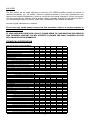
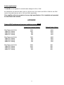
E45
OWNER’S
MANUAL
(BG version)
2
MC AUDIO Ltd.,
Units 6-8, Kingsgate,
Heathpark Industrial Estate,
HONITON,
Devon EX14 1YG
England
Tel: ++(0)1404.44633 Fax: ++(0)1404.44660
www.mc2-audio.co.uk
CONTENTS
EC DECLARATION OF CONFORMITY
3
IMPORTANT SAFETY INSTRUCTIONS
4, 5, 6, 7
INSTALLATION
4
8
8
Electrical
RF Emissions
Mechanical
GENERAL INFORMATION
9
CONNECTIONS
Inputs
Outputs
Bridged Operation
10
10
11
OPERATION
Switching on
Level controls
Bar signal indicators
-3dB indicator
Limiters
PRC indicators
Temperature control
Fault indicator
Bridged LED
11
11
11
11
11
11
12
12
12
MAINTENANCE
12
TECHNICAL SPECIFICATION
13
APPENDIX
14
Table of PRC settings
2
3
Important Safety Instructions
1)
Read these instructions.
2)
Keep these instructions.
3)
Heed all warnings.
4)
Follow all instructions.
5)
Do not block any ventilation openings, install in accordance with the manufacturer’s
instructions.
6)
Unplug this apparatus during lightning storms or when unused for long periods of time.
7)
Clean only with a dry cloth.
8)
Do not use this apparatus near water; the apparatus shall not be exposed to dripping or
splashing and no objects filled with liquids, such as vases shall be placed on the
apparatus.
9)
Refer all servicing to qualified service personnel. Servicing is required when the
apparatus has been damaged in any way, such as if the power-supply cord or plug is
damaged, liquid has been spilled or objects have fallen into the apparatus, the
apparatus has been exposed to rain or moisture, does not operate normally, or has
been dropped.
Installation Instructions: ELECTRICAL
The amplifier has been manufactured to comply with your local power supply requirements, but before
connecting the unit to the supply, ensure that the voltage (printed on the rear panel) is correct.
Make sure power outlets conform to the power requirements listed on the back of the unit. Damage
caused by connecting to improper AC voltage is not covered by the warranty.
SAFETY WARNING
Where a MAINS plug or appliance coupler is used as the disconnect device, it should remain readily
operable.
Where the amplifier is mounted in a rack and permanently connected to the mains, then the rack should
be installed with a readily accessible connector or an ALL POLE circuit breaker.
This unit is fitted with a 3-wire power cord. For safety reasons, THE EARTH LEAD SHOULD NOT BE
DISCONNECTED IN ANY CIRCUMSTANCE. If ground loops are encountered consult the section on
‘Input Connections’ later in this manual.
THE WIRING COLOURS ARE:
230V AREAS: EARTH = GREEN AND YELLOW
NEUTRAL = BLUE
LIVE = BROWN
120V AREAS:
EARTH = GREEN
NEUTRAL = WHITE
LIVE = BLACK
WARNING To reduce the risk of fire or electric shock, do not expose this apparatus to rain or
moisture.
TO AVOID ELECTRICAL SHOCK DO NOT REMOVE COVERS. REFER ALL SERVICING TO QUALIFIED
PERSONNEL.
4
DO NOT USE THE UNIT IF THE ELECTRICAL POWER CORD IS FRAYED OR BROKEN. The power supply
cords should be routed so that they are not likely to be walked on or pinched by items placed upon or
against them, paying particular attention to cords and plugs and the point where they exit from the
appliance.
ALWAYS OPERATE THE UNIT WITH THE AC GROUND WIRE CONNECTED TO THE ELECTRICAL SYSTEM
GROUND. Precautions should be taken so that the means of grounding of a piece of equipment is not
defeated.
DO NOT REMOVE THE LID. Removing the lid will expose you to potentially dangerous voltages. There
are no user serviceable parts inside.
5
WARNING: Apparatus with CLASS I construction shall be connected to a MAINS socket outlet with a protective
earthing connection.
WARNING: To prevent injury, this apparatus must be securely attached to the rack in accordance with the installation
instructions.
1.
Read these instructions.
2.
Keep these instructions.
3.
Heed all warnings.
4.
Follow all instructions.
5.
Do not use this apparatus near water.
6.
Clean only with a dry cloth.
7.
Do not block any ventilation openings, install in
accordance with the manufacturer’s instructions.
8.
Do not install near any heat sources, such as radiators,
heat registers, stoves or other apparatus (including
amplifiers) that produce heat.
9.
Protect the power cord from being walked on or
pinched particularly at plugs, convenience receptacles
and the pint where they exit from the apparatus.
10. The mains circuit breaker shall remain readily
accessible.
11. Only use attachments/accessories specified by the
manufacturer.
12. Use only with the cart, tripod, bracket or table
specified by the manufacturer, or sold with the
apparatus. When a cart is used, use caution when
moving the cart/apparatus combination to avoid injury
from a tip over.
13. Disconnect this apparatus during lightning storms or
when unused for a long period of time.
14. Refer all servicing to qualified service personnel.
Servicing is required when the apparatus has been
damaged in any way, such as if the power-supply cord
or plug is damaged, liquid has been spilled or objects
have fallen into the apparatus, the apparatus has been
exposed to rain or moisture, does not operate
normally, or has been dropped.
15. Do not expose this equipment to dripping or splashing
and ensure that no objects filled with liquids, such as
vases, are placed on the equipment.
16. To completely disconnect this equipment from the AC
mains, disconnect the power cord from the mains
circuit breaker.
17. Where the amplifier is mounted in a rack and
permanently connected to the mains, then the rack
should be installed with a readily accessible connector
or an ALL POLE circuit breaker with 3mm breaking
distances.
18. This unit is fitted with a 3-wire power cord. For safety
reasons, THE EARTH LEAD SHOULD NOT BE
DISCONNECTED IN ANY CIRCUMSTANCE.
19. The cooling fans suck cool air in through the front and
blow hot air out at the rear of the unit through the
ventilating grills. The front and rear of the amplifier
should have free exposure to the air (i.e. in a rack
leave the front and rear doors off), with 2cm air gap at
the sides and top. IF AIR IS NOT ALLOWED TO
ESCAPE FROM THE REAR, OVER-HEATING WILL
OCCUR. Take care when mounting other equipment in
the same rack.
20. The mains switch on the amplifiers only switches one
pole of the mains supply, therefore for units with a
detachable cord to be fully disconnected from the
mains, the mains disconnect device (ie mains plug or
mains coupler) should remain readily operable. For
units with a fixed mains lead the external all pole
circuit breaker with 3mm breaking distances is the
disconnect device and therefore the installation of the
amplifier shall be carried out in accordance with all the
applicable installation rules.
6
ATTENTION: Appareils de construction de CLASSE I doit être raccordé au réseau électrique via une prise de courant reliée à la
terre.
ATTENTION: Pour éviter toute blessure, cet appareil doit être solidement fixé à la torture, conformément aux instructions
d'installation.
1.
Lisez ces instructions.
2.
Gardez ces instructions.
3.
Faites attention à tous les avertissements.
4.
Suivez toutes les instructions.
5.
N'utilisez pas cet appareil près de l'eau.
6.
Faites le ménage seulement avec un tissu sec.
7.
Ne bloquez pas d'ouvertures de ventilation, installez
conformément aux instructions du fabricant.
8.
N'installez près d'aucunes sources de chaleur, comme les
radiateurs, les registres de chaleur, les cuisinières ou
d'autre appareil (en incluant des amplificateurs) qui
produisent la chaleur.
9.
Protégez la corde de pouvoir d'être marché sur ou pincé
particulièrement aux prises de courant, les réceptacles
d'avantage et la pinte où ils sortent de l'appareil.
10.
Le disjoncteur de conduite principale restera sans hésiter
accessible.
11.
Utilisez seulement des attachements/accessoires spécifiés
par le fabricant.
12.
Utilisez seulement avec le chariot, le trépied, la parenthèse
ou la table spécifiée par le fabricant, ou vendu avec
l'appareil. Quand un chariot est utilisé, utilisez la prudence
en déplaçant la combinaison de chariot/appareil pour éviter
la blessure d'un bout.
13.
Débranchez cet appareil pendant les tempêtes de foudre
ou quand neuf pendant un long terme de temps.
7
14.
Renvoyez tout l'entretien au personnel de service qualifié.
L'entretien est exigé quand l'appareil a été nui de toute
façon, comme si la corde de pouvoir provision ou la prise
de courant sont nuis, le liquide a été déversé ou les objets
sont tombés dans l'appareil, l'appareil a été exposé pour
pleuvoir ou l'humidité, n'opère pas normalement, ou a été
baissé.
15.
N'exposez pas cet équipement au fait de tomber goutte à
goutte ou au fait d'éclabousser et garantissez qu'aucun
objet rempli des liquides, comme les vases, n'est placé sur
l'équipement.
16.
Pour complètement débrancher cet équipement de la
conduite principale de courant alternatif, débranchez la
corde de pouvoir du disjoncteur de conduite principale.
17.
Où l'amplificateur est monté dans un égouttoir et en
permanence raccordé à la conduite principale, alors
l'égouttoir devrait être installé avec un connecteur sans
hésiter accessible ou TOUT le disjoncteur de PÔLE avec 3
millimètres cassant des distances.
18.
Cette unité est correspondue avec une corde de pouvoir de
3 fils. Pour les raisons de sécurité, l'AVANCE DE TERRE NE
DEVRAIT ÊTRE DÉBRANCHÉE DANS AUCUNE
CIRCONSTANCE.
19.
Les ventilateurs engloutissent l'air frais par le front et
soufflent l'air chaud à l'arrière de l'unité par les grils
aérants. Le front et l'arrière de l'amplificateur devraient
avoir l'exposition libre à l'air (c'est-à-dire dans un égouttoir
omettent les portes de devant et arrière), avec le trou
aérien de 2 centimètres aux côtés et au haut. Si on NE
PERMET PAS QUE D'AIR S'ÉCHAPPE DE L'ARRIÈRE, LE
FAIT DE SURCHAUFFER SE PRODUIRA. Faites attention en
montant d'autre équipement dans le même égouttoir.
20.
L'interrupteur principal sur les amplificateurs ne coupe
qu'un pôle de l'alimentation secteur. le cordon IEC
permettra de déconnecter l'appareil de l'alimentation
secteur, pour cette raison l'accès à ces fiches (fiche mâle
ou
femelle)
doit
être
facilités.
Pour les appareils avec un câble d'alimentation fixe sans
fiche secteur, le dispositif de coupure omnipolaire ayant
une distance d'ouverture de contact d'au moins 3mm, sera
le dispositif permettant la déconnexion complète de
l'appareil.
Pour cette raison l'installation et le raccordement de
l'amplificateur devra ce faire conformément au
réglementation en vigueur.
INSTALLATION EMC (RF Emissions)
The high frequency resonant converters in the E Series amplifiers have been designed to have very
low radio frequency (RF) emissions, which can cause interference with other equipment. In order for this
to be optimised, the amplifier should be mounted in a metal rack enclosure, which should have a
separate (technical) Earth. Alternatively a separate earth should be attached to the amplifier at the rear
rack mounting bracket.
INSTALLATION: MECHANICAL
To ensure that this equipment performs to specification, it should be mounted in a suitable rack or
enclosure as described below. Like all high power amplifiers, it should be kept away from other
equipment which is sensitive to magnetic fields. Also, this amplifier may suffer a substantial reduction in
performance if it is subjected to, or mounted close to equipment which radiates high RF fields.
When mounting the amplifier in a rack or enclosure, ensure that:1.
The rear of the unit is adequately supported. The brackets which are supplied fit standard 19 inch
(483mm) rack mounting systems. THE FRONT PANEL IS NOT CAPABLE OF SUPPORTING THE
UNIT ON ITS OWN.
2.
THERE IS ADEQUATE VENTILATION. The cooling fans suck cool air in through the front and blow
hot air out at the rear of the unit through the ventilating grills. IF THIS AIR IS NOT ALLOWED TO
ESCAPE, OVER-HEATING WILL OCCUR. Take care when mounting other equipment in the same
rack.
3.
The rack unit has a separate earth connection (technical earth).
ALSO SEE MAINTENANCE SECTION, page 9.
8
General Information
Your E45 power amplifier utilises a proprietary designed progressive switching rail output, which
enables the extremely high voltage swings and peak power without compromising the sonic quality.
Fan speed is varied as required to keep the amplifier within its temperature limits. Signal limiters are
included to protect speakers from clipped signals.
The amplifiers include full DC and short circuit protection to ensure trouble-free service even in ‘harsher’
environments.
The E SERIES introduces three user-controlled features previously not seen on MC2 Audio
amplifiers:
-3dB indicators
Power reduction control (PRC)
User-settable gain/sensitivity (internal)
The latest version now also has improved signal level indication with 3 green LEDs in a ‘bar chart’
format. This gives a much clearer indication of level to the operator. The -3dB and Limit LEDs continue
the bar format.
-3dB INDICATORS
Part of the front panel signal level display, they will light up when the signal is approximately 3dB below
the limiting point. The limiting point is set during production to be at the onset of clipping. The response
times of the -3dB indicators (YELLOW) are faster than those of the limit indicators (ORANGE).
Power Reduction Circuit (PRC)
This enables the user to set a maximum output power level below the rated output of the amplifier. This
reduction is controlled by switches on the rear panel, 2 per channel. Each channel has an LED indicator
(GREEN) active when either PRC switch is selected. A full table of PRC settings and the resulting outputs
are given in the Appendix. The possible settings are: -2dB, -4dB, -6dB. This relates to the maximum
output of the amplifier. (See the chart in the Appendix section at the end of this manual.)
In bridged mode the Channel A PRC circuit operates over both Channel A and B. In this mode Channel
B PRC is not used and is out of circuit.
Notes on Dynamic Amplifiers
The E45 is the very latest example of a ‘dynamic amplifier’. This new ‘breed’ of power amplifiers
provide very high peak power levels in a much smaller, and lighter, package than previously possible
with conventional amplifiers. They are designed specifically for today’s high power audio installations,
which use multiple speakers with electronic crossovers or speaker controllers. These systems can handle
very high transient signals which far exceed their RMS power rating. The E Series amplifiers have
been designed to match this requirement and can deliver huge levels of power for short durations (just
under a second). In order to protect themselves and the loudspeakers that they are driving, continuous
signals, such as sine waves, are automatically detected and reduced (ramped down) to a safe level.
When trying to measure the power output however, continuous signals will give totally incorrect
results. A dynamic signal, such as a tone burst, should be used and the levels measured by monitoring
the waveform on an oscilloscope. The power envelope can then be accurately measured.
9
Connections
INPUTS
The inputs are made via 3-pin XLR connectors, which are electronically balanced and should be
connected via a high grade twin core screened cable, as follows:PIN1 - Screen (see note)
PIN2 - Hot (signal +)
PIN3 - Cold (signal -)
The amplifier is designed to operate with fully balanced equipment and ground loops or loss of
performance may be experienced if connected to unbalanced sources. If it is unavoidable however, the
following wiring should be used. The cable should still be twin core plus screen.
PIN1 - Screen - connected to the chassis of the unbalanced equipment - or left disconnected at the
unbalanced end.
PIN2 - Signal Hot
PIN3 - Signal Cold
Note:
This amplifier is wired to the latest industry recommendations. PIN1 is connected directly to the
chassis/mains earth. If ground loops (mains hum) are encountered remove the screen
connection from the other end of the cable and leave it open circuit. If problems persist, consult
your dealer/supplier, DO NOT TAMPER WITH OR ALTER ANY GROUND (EARTH) CONNECTIONS
INSIDE THE AMPLIFIER.
For BRIDGED OPERATION input should be made to channel A only and the rear panel switch set for
bridged mode.
OUTPUTS
Channel A and Channel B speaker outputs are via Neutrik Speakon connectors. Only 2 of the 4 poles are
used. 2-pole (NL2FC) or 4-pole (NL4FC) connectors can be used.
Terminations are as follows :-
Pin
Pin
+1 = +ve
-1 = -ve
ALSO SEE BRIDGED CONNECTION. (Page 8)
NOTE: 1. Negative (-ve) output terminals must not be joined together, since they are not both at 0V.
Because the currents involved are very high, the speaker cables should conform to the following
minimum requirements, otherwise the losses will cause the cables to get hot and audio power
will be reduced:
E45
- 20A into 4 ohm speaker loads.
10
BRIDGED (MONO) MODE
Use centre Speakon connector marked ‘BRIDGED’ and connect as follows:
For bridged operation:
Pin
Pin
For 4-pole connection to both channels:
(Bridged switch de-selected [ie Out])
Pin
Pin
Pin
Pin
12+
1+
12+
2-
=
=
-ve (Ch A)
+ve (Ch B)
=
=
=
=
Ch.
Ch.
Ch.
Ch.
A
A
B
B
+ve
-ve
+ve
–ve
When operating in bridged mode, the minimum impedances are doubled. The minimum load
in bridged mode is 4 ohms.
LINK SOCKET
Each channel is provided with a 3-pin XLR connector marked ‘LINK’ which allows the input signal to be
linked to further amplifiers etc. The connections are the same as for the input XLR.
Operation
SWITCHING ON
At ‘switch-on’ the protection circuit will initially activate whilst the circuits stabilise. Assuming no faults
are detected after a few seconds, only the ‘POWER’ LED (and ‘SIGNAL’ indicators if signal is applied) will
illuminate.
PANEL CONTROLS AND INDICATORS
Level controls
These are analogue controls allowing precise level settings. Note that in ‘BRIDGED’ mode only ‘channel
A’ control is active.
Signal Indicators (3 Green LEDs)
These are active from a minimum output level of approximately 10 Watts and are only an indication of
signal level.
-3dB Indicators (yellow LED)
These are active when the signal is 3dB below the limiting level.
Limiters (Red LED)
The E Series amplifiers incorporate signal limiters, which are preset to prevent clipping with high levels
of drive. The amber LEDs on the front panel illuminate to indicate operation of the limiters.
PRC Indicators (green LED)
These indicate when the PRC circuit for that specific channel has been selected with the rear panel
switches.
11
Temperature Control
The cooling fans respond to temperature sensors within the unit to maintain a safe operating
temperature. In the event of excessive temperature, the protection circuit will operate, disabling the
output. The red ‘AUDIO-PROTECT’ (A/P) LED will indicate this condition. (See fault indicator.)
There are 4 fans connected permanently with variable speed and a jumper link to enable them from
cold.
Normal dynamic signals will not cause the amplifier to overheat unless the ventilation is
inadequate. (See installation section and maintenance section.)
Fault Indicator (Audio Protection – red LED)
If the outputs are shorted or if DC is present, the protection circuit will disengage the outputs and the
A/P LED will illuminate. The amplifier will continue to be monitored and depending on the type of fault,
will either reset after the fault has cleared or require manual resetting by switching off at the mains
switch and then on again after a few seconds. (See also temperature control above.)
Temperature related faults will reset once the unit has cooled sufficiently.
Output short circuits will require manual reset after clearing the fault.
Bridged LED (green)
This indicates the position of the switch on the rear panel and is illuminated when bridged mode is
selected with the switch pressed in.
Maintenance
CAUTION: These servicing instructions are for use by qualified personnel only. Ensure that
Electrical power to the unit is disconnected before carrying out any maintenance.
GAIN/SENSITIVITY SETTINGS
Gain settings are changed internally by simple jumper links. Two rows of pins marked - GAIN A and
GAIN B - are situated on the input PCB (PCB701). A jumper link sets the gain and the settings are as
follows:
Link 1 & 2
Link 3 & 4
Link 2 & 3
NOTE:
gives
gives
gives
32dB gain
26dB gain
approx. 35.75dB gain =
6dBu/1.5V sensitivity E45
Factory setting is normally link 1 & 2 = 32dB gain.
Setting higher gain does not change the maximum available power but changes the level of
signal input to achieve maximum power. In any case, provided that the input signal is less
than 20dBu/7.7V, the built in limiter circuit will prevent distortion within the amplifier.
The gain should be set to match the signal from the source, e.g. mixer, controller, equaliser
etc.
12
AIR FILTER
The filter behind the air intake apertures on the front of E SERIES amplifiers should be cleaned or
replaced periodically, e.g. 3-6 months. (Filters in amplifiers located in more 'dirty' atmospheres may
require more frequent maintenance). Access is via the blue front panel retained by 2.5mm Hex screws.
The filter should be 'dry' cleaned, using a vacuum cleaner preferably. Running the unit without a filter is
not recommended unless it is within a 'clean room'. Replacement filter material is available.
No other regular maintenance is required.
If you have any doubt about carrying out this procedure, refer to a service engineer or
contact your dealer.
IF YOUR AMPLIFIER DEVELOPS A FAULT, PLEASE REFER TO YOUR SUPPLIER FOR SERVICE
AND TECHNICAL SUPPORT. DO NOT ATTEMPT TO REPAIR THE FAULT YOURSELF AS THIS
WILL INVALIDATE THE WARRANTY.
TECHNICAL SPECIFICATION
Main Specifications - E series Amplifiers
Parameter (Units)
E90
E45
E25
E15
E100
E475
8 ohms
2500
4 ohms
4800
1250
700
450
1400
775
2500
1350
850
2800
2 ohms
900
8200
4200
2400
1550
3700
NA
8 ohms
9600
5000
2700
1700
5300
1800
4 ohms
16400
8400
4800
3100
7400
NA
@1kHz (@1dB below max output power) <
0.15
0.015
0.008
0.008
0.08
0.008
@20Hz to 20kHz (@3dB below max output power) <
0.5
0.05
0.03
0.03
0.15
0.03
32/36/39
26/32/36
26/32/33
26/31/32
26/32/36
26/31/32
Output Power (per channel) (Watts)
Output Power (bridged) ( Watts)
THD+N:(%)(4 ohms)
Gain Options (dB)
Sensitivity Options (for maximum power) (dBu)
Sensitivity Options (for maximum power) (Volts)
Frequency Response - 20Hz to 20kHz (dB)
Power Consumption: Nominal @ 240v (4 ohms)(Amps)
Power Consumption: Nominal @ 120v (4 ohms)(Amps)
13/9/6
15.7/9.7/5.7
13/7/6
11/6/5
16/10/6
11/6/5
3.5/2.2/1.5
4.7/2.4/1.5
3.5/1.7/1.5
2.7/1.5/1.4
4.9/2.5/1.5
2.7/1.5/1.4
±1.0
+0 / -0.3
+0 / -0.3
+0 / -0.3
±0.5
+0 / -0.3
5.6
4.5
3
2.1
7
2.7
11.2
9
6
4.2
14
5.4
Dimensions: (mm)
Amplifier: H x W x D
88 x 482 x 428
Boxed (shipping UK): H x W x D
230 x 580 x 560
Boxed (shipping - all except UK): H x W x D
250 x 610 x 600
Weight: (Kgs)
Amplifier:
11.78
11.42
10.16
9.8
12
10.62
Boxed:(shipping)
13.78
13.42
11.92
11.66
14
12.62
Additional Specifications
Input Impedance - Active balanced (k ohms)
Input CMRR (dB)
Hum & Noise (dB below max output)
Damping Factor: @1kHz into 8 ohms
Signal Limiters - (set to prevent excessive clipping)
Protection: Short circuit / DC output / Temperature
Mains in-rush control.
Output Power (watts) into 8 ohms
20
20
20
20
20
20
>60
>60
>60
>60
>60
>60
-105
-106
-105
-105
-105
-105
>400
>400
>400
>400
>400
>400
Yes
Yes
Yes
Yes
Yes
Yes
Yes
Yes
Yes
Yes
Yes
Yes
Yes
Yes
Yes
Yes
Yes
Yes
Sine wave @ 1kHz
2400
1100
650
400
1150
725
Continuous music with Crest Factor of 2.8 (9dB)
2400
1200
675
425
1300
750
Continuous music with Crest Factor of 4.8 (14dB)
2500
1250
700
450
1400
775
Continuous music with Crest Factor of 7.8 (18dB)
2600
1350
725
475
1480
825
Output Power (watts) into 4 ohms
Sine wave @ 1kHz
4500
2050
1200
775
2250
750
Continuous music with Crest Factor of 2.8 (9dB)
4400
2400
1250
825
2600
825
Continuous music with Crest Factor of 4.8 (14dB)
4800
2500
1350
850
2800
900
Continuous music with Crest Factor of 7.8 (18dB)
5000
2700
1350
875
2900
900
Output Power (watts) into 2 ohms
Sine wave @ 1kHz
7200
3300
2200
1350
3200
NA
Continuous music with Crest Factor of 2.8 (9dB)
6800
4100
2300
1500
3600
NA
Continuous music with Crest Factor of 4.8 (14dB)
8200
4200
2400
1550
3700
NA
Continuous music with Crest Factor of 7.8 (18dB)
8900
4300
2600
1600
3700
NA
13
Power requirements
The E45 can be supplied for nominal mains voltage of 115V or 230V.
An internal link can be set to either 100V or 120V for the 115V version and 220V or 240V for the 230V
version. Normally these are set to 120V and 240V respectively.
This amplifier will only operate to its very high specification if it is installed and operated
as described in this manual.
APPENDIX
Table of PRC settings and average relative output - E45
Output Per Channel (Watts)
Bridged Mode (Watts)
Max Power into 4ohm
-2dBu PRC Setting
-4dBu PRC Setting
-6dBu PRC Setting
2250
1400
900
560
6400
4000
2500
1600
Max Power into 8ohm
-2dBu PRC Setting
-4dBu PRC Setting
-6dBu PRC Setting
1200
800
525
350
4400
2800
1800
1200
Max Power into 2ohm
-2dBu PRC Setting
-4dBu PRC Setting
-6dBu PRC Setting
3200
2000
1250
800
N/A
N/A
N/A
N/A
14