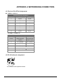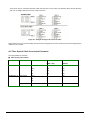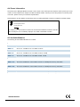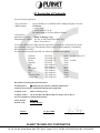
1
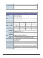
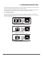
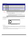
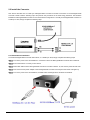
User's Manual GT-902 GT-902S GT-905A GT-906A15 / GT-906B15 GT-906A60 / GT-906B60 GT-906A80 / GT-906B80 10/100/1000Base-T to 1000Base-SX / LX Managed Media Converter Trademarks Copyright © PLANET Technology Corp. 2010. Contents subject to which revision without prior notice. PLANET is a registered trademark of PLANET Technology Corp. All other trademarks belong to their respective owners. Disclaimer PLANET Technology does not warrant that the hardware will work properly in all environments and applications, and makes no warranty and representation, either implied or expressed, with respect to the quality, performance, merchantability, or fitness for a particular purpose. PLANET has made every effort to ensure that this User's Manual is accurate; PLANET disclaims liability for any inaccuracies or omissions that may have occurred. Information in this User's Manual is subject to change without notice and does not represent a commitment on the part of PLANET. PLANET assumes no responsibility for any inaccuracies that may be contained in this User's Manual. PLANET makes no commitment to update or keep current the information in this User's Manual, and reserves the right to make improvements to this User's Manual and/or to the products described in this User's Manual, at any time without notice. If you find information in this manual that is incorrect, misleading, or incomplete, we would appreciate your comments and suggestions. FCC Warning This equipment has been tested and found to comply with the limits for a Class A digital device, pursuant to Part 15 of the FCC Rules. These limits are designed to provide reasonable protection against harmful interference when the equipment is operated in a commercial environment. This equipment generates, uses, and can radiate radio frequency energy and, if not installed and used in accordance with the Instruction manual, may cause harmful interference to radio communications. Operation of this equipment in a residential area is likely to cause harmful interference in which case the user will be required to correct the interference at whose own expense. CE Mark Warning This is a Class A product. In a domestic environment, this product may cause radio interference, in which case the user may be required to take adequate measures. Energy Saving Note of the Device This power required device does not support Standby mode operation. For energy saving, please remove the DC-plug or push the hardware Power Switch to OFF position to disconnect the device from the power circuit. Without removing the DC-plug or switch off the device, the device will still consume power from the power source. In the view of Saving the Energy and reduce the unnecessary power consuming, it is strongly suggested to power off or to remove the DC-plug for the device if this device is not intended to be active. -2- WEEE Warning To avoid the potential effects on the environment and human health as a result of the presence of hazardous substances in electrical and electronic equipment, end users of electrical and electronic equipment should understand the meaning of the crossed-out wheeled bin symbol. Do not dispose of WEEE as unsorted municipal waste and have to collect such WEEE separately. Revision PLANET Managed Gigabit Ethernet Media Converter User's Manual FOR MODELS: GT-902 / GT-902S / GT-905A / GT-906A15 / GT-906B15 / GT-906A60 / GT-906B60 / GT-906A80 / GT-906B80 REVISION: 1.1 (June.2010) Part No.: 2080-AA3450-003 TABLE OF CONTENTS 1. INTRODUCTION............................................................................................................................................................. 1 1.1 PACKAGE CONTENTS .................................................................................................................................................... 1 1.2 HOW TO USE THIS MANUAL ........................................................................................................................................... 1 1.3 ABOUT THE MANAGED MEDIA CONVERTER ...................................................................................................................... 2 1.4 PRODUCT FEATURES .................................................................................................................................................... 3 1.5 PRODUCT SPECIFICATION..................................................................................................................................... 4 2. HARDWARE DESCRIPTION ......................................................................................................................................... 6 2.1 GT-90X FRONT PANEL ................................................................................................................................................. 6 2.1.1 LED Indicators..................................................................................................................................................... 7 2.1.2 GT-90X Rear Panel............................................................................................................................................. 7 2.2 INSTALL THE CONVERTER .............................................................................................................................................. 8 2.2.1 Stand-alone Installation....................................................................................................................................... 8 2.2.2 Chassis Installation and Rack Mounting ........................................................................................................... 10 3. MEDIA CONVERTER MANAGEMENT ....................................................................................................................... 12 3.1 OVERVIEW ................................................................................................................................................................. 12 3.2 MANAGEMENT METHODS ............................................................................................................................................. 12 3.2.1 Web Management............................................................................................................................................. 13 3.2.2 SNMP Management.......................................................................................................................................... 13 3.2.3 PLANET Smart Discovery Utility ....................................................................................................................... 14 3.2.4 Login the Managed Media Converter ................................................................................................................ 15 4. WEB MANAGEMENT................................................................................................................................................... 16 4.1 MAIN MENU ............................................................................................................................................................... 16 4.2 SYSTEM ..................................................................................................................................................................... 17 4.2.1 System Information ........................................................................................................................................... 17 4.2.2 IP Configuration ................................................................................................................................................ 18 4.2.3 Password Setting .............................................................................................................................................. 19 4.2.4 Firmware Upgrade ............................................................................................................................................ 20 4.2.5 SNMP Management.......................................................................................................................................... 24 4.2.6 Factory Default.................................................................................................................................................. 26 4.2.7 System Reboot.................................................................................................................................................. 27 4.3 PORT MANAGEMENT ................................................................................................................................................... 29 4.3.1 Port Configuration ............................................................................................................................................. 29 4.3.2 Port Status ........................................................................................................................................................ 32 4.3.3 Port Statistics .................................................................................................................................................... 33 4.4 CONVERTER CONFIGURATION ...................................................................................................................................... 34 4.5 VLAN ....................................................................................................................................................................... 35 4.5.1 VLAN Group...................................................................................................................................................... 37 4.5.2 VLAN Per Port Setting ...................................................................................................................................... 39 4.5.3 Q-in-Q VLAN Setting......................................................................................................................................... 40 4.6 QUALITY OF SERVICE .................................................................................................................................................. 41 4.7 OAM SETUP .............................................................................................................................................................. 44 -4- 4.7.1 Local TS-1000 OAM Setup ............................................................................................................................... 44 4.7.2 Remote TS-1000 OAM Setup ........................................................................................................................... 45 4.7.3 TS-1000 Loop Back Test .................................................................................................................................. 47 4.7.4 802.3ah Setup................................................................................................................................................... 49 4.7.5 802.3ah Loop Back Test ................................................................................................................................... 50 4.8 SECURITY .................................................................................................................................................................. 52 4.9 LOGOUT..................................................................................................................................................................... 53 5. TROUBLESHOOTING.................................................................................................................................................. 54 APPENDIX A NETWORKING CONNECTION ................................................................................................................. 55 A.1 DEVICE‘S RJ-45 PIN ASSIGNMENTS ............................................................................................................................. 55 A.2 RJ-45 CABLE PIN ASSIGNMENT .................................................................................................................................... 55 A.3 FIBER OPTICAL CABLE CONNECTION PARAMETER ......................................................................................................... 56 A.4 POWER INFORMATION ................................................................................................................................................. 57 A.5 AVAILABLE MODULES.................................................................................................................................................. 57 -5- 1. INTRODUCTION 1.1 Package Contents Check the contents of your package for following parts: ● Managed Gigabit Ethernet Media Converter x1 ● CD-ROM User's Manual x1 ● Quick Installation Guide x1 ● External DC 5V / 2A Power Adapter x 1 If any of these are missing or damaged, please contact your dealer immediately, if possible, retain the carton including the original packing material, and use them against to repack the product in case there is a need to return it to us for repair. #Notice: GT-905A is with one vacant SFP module slot. The 1000Base-SX / LX SFP module is not bundled with in the package. 1.2 How to Use This Manual The Managed Media Converter User’s Manual is structured as followings: Section 2, Hardware Installation It explains the functions of Managed Media Converter and how to install the Managed Media Converter. Section 3, Media Converter Management It contains information about how to manage the Managed Media Converter. Section 4, Web Management It contains information about the management function from the Managed Media Converter. Section 5, Troubleshooting It contains troubleshooting guide of Managed Media Converter. Appendix A It contains cable information of Managed Media Converter. The term of “Managed Media Converter” In the following section of this user’s manual means the GT-90x. -1- 1.3 About the Managed Media Converter The Managed Media Converter GT-90x provide conversion between 10/100/1000Base-T and 1000Base-SX /LX network. There are SC / LC / WDM connectors and single-mode / multi-mode media for your needs. Ethernet signal that allows two type segments connect easily, efficiently and inexpensively. This Managed Media Converter can be used as a stand-alone unit or as a slide-in module to the PLANET Media Converter Chassis (MC-700, MC-1500 and MC-1500R / MC-1500R48). The Managed Media Converter equipped with remote Web / SNMP interface. With its built-in Web-based management, the Managed Media Converter offers an easy-to-use, platform-independent management and configuration facility and can be programmed for advanced management functions. Such as IP address Configuration / DHCP Client function, password setting / firmware upgrade, system reboot / factory default, port configuration that include TP / Fiber port speed duplex mode setting, flow control setting and Ingress/Egress bandwidth control setting, converter configuration that include maximum packet length setting, Broadcast / Multicast / Unicast storm control setting, 16 IEEE 802.1Q VLAN groups support and powerful Q-in-Q VLAN function, Quality of Service (QoS), TS-1000 / IEEE 802.3ah OAM function and TCP & UDP filter function. It supports standard Simple Network Management Protocol (SNMP) and can be managed via any standard-based management software as well. With Gigabit mini GBIC interface, the GT-905A is with high reliability and flexibility to extend the distance from 220m to 120Km. It depends on the Gigabit mini GBIC modules. ■ Application Fiber-optic Networking for ISP, enterprise, and home With high performance of data transmission and easy installation, the Managed Media Converter can build an ISP network solution of FTTH (Fiber to the Home) or FTTC (Fiber to the Curb) for ISPs and FTTB (Fiber to the Building) for small office network environment from enterprises. The Web Management helps network administrators to monitor and setup the converter, speed and duplex through web browsers. -2- 1.4 Product Features Complies with IEEE 802.3 10Base-T, IEEE 802.3u 100Base-TX, IEEE 802.3ab 1000Base-T, IEEE 802.3z 1000Base-SX/LX One-channel media conversion between 10/100/1000Base-T and 1000Base-SX / LX TP port supports 10/100/1000Base-T auto-negotiation and auto-MDI/MDI-X 1000Base-SX: 50/125μm or 62.5/125μm multi-mode fiber cable, up to 220/550m on GT-902 1000Base-LX: 9/125μm single-mode cable provides long distance for 10km on GT-902S 1000Base-LX WDM interface for up to 15km (single-mode fiber 9μm/125μm) on GT-906A15/B15 1000Base-LX WDM interface for up to 60km (single-mode fiber 9μm/125μm) on GT-906A60/B60 1000Base-LX WDM interface for up to 80km (single-mode fiber 9μm/125μm) on GT-906A80/B80 1000Base-T: 2-pair Cat. 5/5e/6 UTP cable, up to 100 meters Compacts size for working with PLANET MC family Media Chassis ( MC-700/1500/1500R / 1500R48) Wall-mountable hardware designed Built-in IP-Base Web interface for remote management Layer 2 Management Feature ; Store-and-Forward mechanism ; Built-in Web operation interface for remote management and setup ; Manual IP address setting / DHCP client for IP address assignment ; SNMP v1 / v2c monitor / private Enterprise MIB ; Event trap and SNMP trap support ; Speed duplex mode configuration / Flow Control setting / bandwidth Control on TP / Fiber port ; Supports Port Status / Ethernet Statistics on both TP and Fiber interface ; Supports Maximum frame size to 16K bytes ; Loop detection / Broadcast / Multicast / Unicast storm control ; Management VLAN / 16 IEEE 802.1Q VLAN groups / Q-in-Q VLAN -3- ; 802.1p Tag Priority / IP address priority / IP DSCP option in Quality of Service Mode and Strict Priority / Weighted Round Robin (WRR) QoS policies ; TS-1000 OAM / IEEE 802.3ah OAM / Loop Back Test ; 16 TCP / UDP Filter groups ; Password setting, IP setting and devices description setting through Planet Smart discovery utility ; Firmware upgrade via remote Web interface External DC 5V 2A power supply Compact in size, easy installation LED indicators for easy network diagnosing Reset Button at the front panel for resetting the factory default Choice of fiber-connector from SC, LC, WDM, multi-mode / single-mode fiber /1000Base-SX / LX mini GBIC module 1.5 PRODUCT SPECIFICATION Model GT-902 GT-902S GT-905A GT-906A15 GT-906B15 Hardware Specification Standards Ports Copper Interface IEEE 802.3, 10Base-T IEEE 802.3u, 100Base-TX IEEE 802.3ab, 1000Base-T IEEE 802.3z, 1000Base-SX/LX 1 x 10/100/1000Base-T port, 1 x 1000Base-SX/LX / LX WDM port 1 x 1000Base-SX/LX SFP slot RJ-45 port (Auto-MDI/MDI-X) Twisted Pair Optic Interface SC TX:1550nm RX:1550nm RX:1310nm - -3 dBm +5 dBm -9.5dBm - -9 dBm 0 dBm -13.5 dBm -14.4 dBm - -21 dBm -25 dBm -18 dBm -20 dBm - -3 dBm -3 dBm 1310nm - Max. -4 dBm -3 dBm Min. -9.5 dBm Receive Sensitivity Maximum Input power Twisted-pair Speed Fiber-optic WDM TX:1310nm 850nm Optic Wavelength Launch Power(dBm) SFP 10/20Mbps for Half / Full-Duplex 100/200Mbps for Half / Full-Duplex 2000Mbps for Full-Duplex 2000Mbps for Full-Duplex Power Consumption 10Base-T: 2-pair UTP Cat. 3,4,5, up to 100 m 100Base-TX: 2-pair UTP Cat. 5, up to 100 m 1000Base-T: 4-pair STP Cat 5 up to 100m 50/125μm or 62.5/125μm multi-mode fiber cable, up to 220/550m. 9/125μm single-mode cable, provides long distance for 10/15/20/30/40/50/70/120km (very on fiber transceiver or SFP module) y PWR, y TP LINK/ACT, 1000 y Fiber LINK/ACT 3.8 Watts/ 13 BTU (maximum) Power Input DC 5V / 2A Twisted-pair Cable Fiber-optic Cable LED Indicator -4- Dimensions 94 x 70 x 26mm (W x D x H) Operator Environment Operating temperature: 0 to 50 Degree C; Humidity: 5~90% non-condensing Storage Environment storage temperature: -10 to 70 Degree C; Humidity: 5~90% non-condensing Emissions FCC Class A, CE Class A Model GT-906A60 GT-906B60 GT-906A80 GT-906B80 Hardware Specification Standards Ports Copper Interface IEEE 802.3, 10Base-T IEEE 802.3u, 100Base-TX IEEE 802.3ab, 1000Base-T IEEE 802.3z, 1000Base-LX 1 x 10/100/1000Base-T port, 1 x 1000Base-LX WDM port RJ-45 port (Auto-MDI/MDI-X) Twisted Pair Optic Interface WDM TX:1310nm TX:1550nm TX:1510nm TX:1570nm RX:1550nm RX:1310nm RX:1570nm RX:1510nm Max. +4 dBm +5 dBm +3 dBm +3 dBm Min. -1 dBm 0 dBm -2 dBm -2 dBm Receive Sensitivity -21 dBm -25 dBm -26 dBm -26 dBm Maximum Input power -2 dBm -2 dBm -1 dBm -1 dBm Optic Wavelength Launch Power (dBm) Twisted-pair Speed Fiber-optic 10/20Mbps for Half / Full-Duplex 100/200Mbps for Half / Full-Duplex 2000Mbps for Full-Duplex 2000Mbps for Full-Duplex Twisted-pair 10Base-T: 2-pair UTP Cat. 3,4,5, up to 100 m 100Base-TX: 2-pair UTP Cat. 5, up to 100 m 1000Base-T: 4-pair STP Cat 5 up to 100m Fiber-optic Cable Cable 50/125μm or 62.5/125μm multi-mode fiber cable, up to 550m. 9/125μm single-mode cable, provides long distance for 60/80km Power Consumption y PWR, y TP LINK/ACT, 1000 y Fiber LINK/ACT 3.8 Watts/ 13 BTU (maximum) Power Input DC 5V / 2A Dimensions 94 x 70 x 26mm (W x D x H) Operator Environment Operating temperature: 0 to 50 Degree C; Humidity: 5~90% non-condensing Storage Environment storage temperature: -10 to 70 Degree C; Humidity: 5~90% non-condensing Emissions FCC Class A, CE Class A LED Indicator -5- 2. HARDWARE DESCRIPTION This product provides three different running speeds – 10Mbps, 100Mbps and 1000Mbps in the same Managed Media Converter and automatically distinguishes the speed of incoming connection. This section describes the functionalities of GT-90X’s components and guides how to install it on the desktop or shelf. Basic knowledge of networking is assumed. Please read this chapter completely before continuing. 2.1 GT-90X Front Panel The Front Panel of the Managed Media Converter consists of one 1000Base-SX / 1000Base-LX / mini-GBIC SFP / 1000Base-LX WDM ports and one Auto-Sensing 10/100/1000Mbps Ethernet RJ-45 Port. Figure 2-1 & 2-2 & 2-3 shows a front panel of Managed Media Converter. Figure 2-1 PLANET GT-902 / GT-902S Front Panel Figure 2-2 PLANET GT-905A Front Panel Figure 2-3 PLANET GT-906A/B Front Panel -6- 2.1.1 LED Indicators LED Color Description PWR Green Lit: When +5VDC power detected. Fiber LNK/ACT Green TP LNK/ACT Green TP 1000 Green Lit: To indicate the link through that fiber port is successfully established. Blink: Indicate that the Fiber port is actively sending or receiving data over that port. Lit: To indicate the link through that port is successfully established. Blink: Indicate that the port is actively sending or receiving data over that port. Lit: When the port runs in 1000Mbps Full duplex mode #Notice: Off: When the port runs in 10/100Mbps Half / Full duplex mode. To press and release the RESET button. The GX-90x will back to the factory default mode. Be sure that you backup the current configuration of GT-90X; else the entire configuration will be erased when pressing the “RESET” button. • Press and release the RESET button shortly, the device will be rebooted. • Press the RESET button more than 10 seconds, the device will back to the factory default mode; the entire configuration will be erased. 2.1.2 GT-90X Rear Panel The rear panel of the Managed Media Converter indicates one DC jack, which accepts input power with 5V DC 2A. ■ GT-90x series Figure 2-4 Rear Panel of GT-90x Power Notice: 1. The device is a power-required device, it means, it will not work till it is powered. If your networks should active all the time, please consider using UPS (Uninterrupted Power Supply) for your device. It will prevent you from network data loss or network downtime. 2. In some area, installing a surge suppression device may also help to protect your Managed Media Converter from being damaged by unregulated surge or current to the converter or the power adapter. -7- 2.2 Install the Converter This section describes how to install your Managed Media Converter and make connections to the Managed Media Converter. Please read the following topics and perform the procedures in the order being presented. The hardware installation of Managed Media Converter do not need software configuration. To install your Managed Media Converter on a desktop or shelf, simply complete the following steps. 2.2.1 Stand-alone Installation To install a Managed Media Converter stand-alone, on a desktop or shelf, simply complete the following steps: Step 1: Turn off the power of the device/station in a network to which the Managed Media Converter will be attached. Step 2: Ensure that there is no activity in the network. Step 3: Attach fiber cable from the Managed Media Converter to the fiber network. TX, RX must be paired at both ends. Step 4: Connect the 5V DC power adapter to the Managed Media Converter and verify that the Power LED lights up. Step 5: Turn on the power of the device/station; the PWR LEDs should light when all cables are attached. -8- #Notice: Please refers to APPENDIX-A for detailed wiring information of the Managed Media Converter. To prevent from optic acceptor malfunction, check the both wires / transmitter before power on the converter. GT-905A Installation GT-905A is with high reliability and flexibility to extend the distance from 220m to 120Km. It depends on the Gigabit mini GBIC modules. The SFP transceivers are hot-plug and hot-swappable. You can plug-in and out the transceiver to/from any SFP port without having to power down the converter. To install GT-905A with 1000Base-SX / LX SFP, simply complete the following steps: Step 1: Precede with the steps 4 and steps 5 of session 2.2.1 Stand-alone Installation to connect the network cabling and supply power to your converter. Step 2: Slot in the 1000Base-SX / LX SFP. Make sure both side of the SFP transceiver are with the same media type, for example: 1000Base-SX / 220m & 550m to 1000Base-SX / 220m & 550m, 1000Base-LX / 10km to 1000Base-LX / 10km Step 3: Connect the fiber cable. Attach the duplex LC connector on the network cable into the SFP transceiver. #Notice: It recommends using PLANET MGB series 1000Base-SX / LX / LX WDM SFP on the GT-905A. If you insert a SFP transceiver that is not supported, the GT-905A will not recognize it. -9- 2.2.2 Chassis Installation and Rack Mounting To install the Managed Media Converter in a 10-inch or 19-inch with standard rack, follow the instructions described below. Step 1: Place your Managed Media Converter on a hard flat surface, with the front panel positioned towards your front side. Step 2: Carefully slide in the module until it is fully and firmly fitted into the slot of the chassis. Figure 2-5: Insert a Managed Media Converter into an available slot Step 3: Attach a rack-mount bracket to each side of the Chassis with supplied screws attached to the package. Step 4: After the brackets are attached to the chassis, use suitable screws to securely attach the brackets to the rack, as shown in Figure 2-6. Step 5: Precede with the steps 4 and steps 5 of session 2.2.1 Stand-alone Installation to connect the network cabling and supply power to your Chassis. Caution: You must use the screws supplied with the mounting brackets. Damage caused to the parts by using incorrect screws would invalidate your warranty. -10- Figure 2-6 Mounting the Chassis in a Rack -11- 3. MEDIA CONVERTER MANAGEMENT This chapter describes how to manage the Managed Media Converter. Topics include: - Overview - Management methods - Assigning an IP address to the Managed Media Converter - Logging on to the Managed Media Converter 3.1 Overview This chapter gives an overview of Managed Media Converter management. The GT-90X provides a simply WEB browser interface. Using this interface, you can perform various Managed Media Converter configuration and management activities, including: System Port Management Converter Configuration VLAN Quality of Service OAM Setup Security Logout Please refer to the following Chapter 4 for more details. 3.2 Management Methods The way to manage the GT-90X: - Web Management via a network or dial-up connection. -Using SNMP Network Management Station. -12- 3.2.1 Web Management The PLANET Managed Media Converter provides a built-in browser interface. You can manage the Managed Media Converter remotely by having a remote host with Web browser, such as Microsoft Internet Explorer, Netscape Navigator or Mozilla Firefox. The following shows how to startup the Web Management of the Managed Media Converter, please note the Managed Media Converter is configured through an Ethernet connection, make sure the manager PC must be set on the same IP subnet address, for example, the default IP address of the Managed Media Converter is 192.168.0.100 (the factory-default IP address), then the manager PC should be set at 192.168.0.x (where x is a number between 1 and 254, except 100), and the default subnet mask is 255.255.255.0. Use Internet Explorer 5.0 or above Web browser, enter default IP address http://192.168.0.100 After entering the username and password (default user name and password is “admin”) in login screen then the Web main screen appears. 3.2.2 SNMP Management You can manage the Managed Media Converter across a LAN using an SNMP Network Management Station with a graphical user interface. This management method lets you monitor statistical counters and set Managed Media Converter parameters from the remote Network Management Station. Using this management method: - The network must run the IP protocol. - The Managed Media Converter must have an IP address. -13- 3.2.3 PLANET Smart Discovery Utility For easily list the Managed Media Converter in your Ethernet environment, the Planet Smart Discovery Utility from user’s manual CD-ROM is an ideal solution. The following install instructions guiding you for run the Planet Smart Discovery Utility. 1. Deposit the Planet Smart Discovery Utility in administrator PC. 2. Run this utility and the following screen appears. Figure 3-1 Planet Smart Discovery Utility Screen #Notice: If there are two LAN cards or above in the same administrator PC, choose different LAN card by use the “Select Adapter” tool. 3. Press “Refresh” button for list current connected devices in the discovery list, the screen is shown as follow. Figure 3-2 Planet Smart Discovery Utility Screen -14- 3. This utility show all necessary information from the devices, such as MAC Address, Device Name, firmware version, Device IP Subnet address, also can assign new password, IP Subnet address and description for the devices. 4. After setup completed, press “Update Device”, “Update Multi” or “Update All” button to take affect. The meaning of the 3 buttons above are shown as below: Update Device: use current setting on one single device. Update Multi: use current setting on choose multi-devices. Update All: use current setting on whole devices in the list. The same functions mentioned above also can be finding in “Option” tools bar. 5. To click the “Control Packet Force Broadcast” function, it can allow assign new setting value to the Managed Media Converter under different IP subnet address. 6. Press “Connect to Device” button then the Web login screen appears in Figure 3-3. 7. Press “Exit” button to shutdown the planet Smart Discovery Utility. 3.2.4 Login the Managed Media Converter Before you start configure the Managed Media Converter, please note the Managed Media Converter is configured through an Ethernet connection, make sure the manager PC must be set on same the IP subnet address. For example, the default IP address of the Managed Media Converter is 192.168.0.100, then the manager PC should be set at 192.168.0.x (where x is a number between 2 and 254), and the default subnet mask is 255.255.255.0. Use Internet Explorer 6.0 or above Web browser. Enter IP address http://192.168.0.100 (the factory-default IP address) to access the Web interface. When the following login screen appears, please enter the default username and password (default user name and password is "admin"). Press Login to enter the main screen of Managed Media Converter. The login screen in Figure 3-3 appears. Figure 3-3 Login Web Page screen #Notice: 1. For security reason, please change and memorize the new password after this first setup. 2. Only accept command in lowercase letter under web interface. -15- 4. WEB MANAGEMENT The GT-90X Managed Media Converter provide Web interface for management function configuration and make the Managed Media Converter operate more effectively - They can be configured through the Web Browser. A network administrator can manage and monitor the Managed Media Converter from the local LAN. This section indicates how to configure the Managed Media Converter to enable its management function. 4.1 Main Menu After a successful login, the main screen appears, the main screen displays the Managed Media Converter Welcome page. The screen in Figure 4-1 appears. Figure 4-1 Web Main screen As listed at the left of the main screen, the configurable management functions are shown as below: ◆ ◆ System – Provide System configuration of Managed Media Converter. Explained in section 4.2. Port Management – Provide Port Management configuration of Managed Media Converter. Explained in section 4.3. ◆ Converter Configuration – Provide Converter configuration of Managed Media Converter. Explained in section 4.4. ◆ ◆ VLAN – Provide VLAN configuration of Managed Media Converter. Explained in section 4.5. Quality of Service – Provide Quality of Service (QoS) function of the Managed Media Converter. Explained in section 4.6. ◆ OAM Setup – Provide OAM Setup function of the Managed Media Converter. Explained in section 4.7. ◆ Security – Provide Security function of the Managed Media Converter. Explained in section 4.8. ◆ Logout– Provide Logout function of the Managed Media Converter. Explained in section 4.9. -16- 4.2 System 4.2.1 System Information The System Information Web page provides information for the current device. System Information Web page helps network administrator to identify the firmware versions, IP Subnet Address and etc. The screen in Figure 4-2 appears and Table 4-1 describes the System Information object of Managed Media Converter. Figure 4-2 System Information Web page screen The System Information Web page screen includes the following fields: MAC Address Specifies the MAC address of Managed Media Converter. Software Version The current software version running on the Managed Media Converter. IP Address The current IP Address of Managed Media Converter, the default IP Address is 192.168.0.100. Subnet Mask The current Subnet Mask of Managed Media Converter, the default Subnet Mask is 255.255.255.0. Gateway The current gateway of Managed Media Converter, the factory default gateway is 192.168.0.254. Description The current description of Managed Media Converter, the factory default description is GT-90X. Table 4-1 Descriptions of the System Information Web Page Screen Objects -17- 4.2.2 IP Configuration The IP Configuration includes the DHCP Client, IP Address, Subnet Mask, Gateway and Description. The screen in Figure 4-3 appears and Table 4-2 describes the IP Configuration object of Managed Media Converter. Figure 4-3 IP Configuration Web page screen The IP Configuration Web page screen includes the following configurable data: DHCP Client Allow disable or enable the DHCP Client function of the Managed Media Converter, the factory default mode is Disable. IP Address Allow assigning a new IP address for the Managed Media Converter, the factory default IP address is 192.168.0.100. Subnet Mask Allow assigning a new subnet mask for the Managed Media Converter, the factory default subnet mask is 255.255.255.0. Gateway Allow assigning a new gateway for the Managed Media Converter, the factory default gateway is 192.168.0.254. Description Allow to input a new description for the Managed Media Converter, up to maximum 32 characters allow. Apply button Press “Apply” button for save current configuration of Managed Media Converter. Table 4-2 Descriptions of the IP Configuration Web Page Screen Objects #Notice: After change the default IP subnet address, if you forget the IP subnet address. Please press the “Reset” button in the front panel of Managed Media Converter for 10 seconds, the current setting will be lost and the Managed Media Converter will restore to factory default mode. -18- 4.2.3 Password Setting This function provides administrator to secure Web login. The screen in Figure 4-4 & 4-5 appears and Table 4-3 describes the Password Setting object of Managed Media Converter. Figure 4-4 Password Setting Web page screen Figure 4-5 Password Setting Successful Web page screen -19- The Password Setting Web page includes the following configurable data: Login Name Displays the user name (admin). Old Password Enter the old password is required before entering the new password. New Password Specifies the new password. The password is not displayed. As it entered an “y” corresponding to each character is displayed in the field. (The maximum length is 16 characters) Confirm This confirms the new password. The password entered into this field must be exactly the same as the password entered in the Password field. Apply button Press “Apply” button for save current configuration of Managed Media Converter. Table 4-3 Descriptions of the Password Setting Web Page Screen Objects 4.2.4 Firmware Upgrade This function provides Firmware Upgrade of the Managed Media Converter and the screen in Figure 4-6 appears. Figure 4-6 Firmware Upgrade Web page screen -20- Press “Browser” button to find the firmware location administrator PC, The screen in Figure 4-7 appears Figure 4-7 Firmware Upgrade Web page screen After find the firmware location from administrator PC, press “Upgrade” button to start the firmware upgrade process. The screen in Figure 4-8 & 4-9 appears. Figure 4-8 Firmware Upgrade Web page screen -21- Figure 4-9 Firmware Upgrade Web page screen When firmware upgrade process is completed then the following screen appears, please click “here” to re-login the Managed Media Converter with latest firmware and the screen in Figure 4-10 & 4-11 appears. Figure 4-10 Firmware Upgrade Web page screen -22- Figure 4-11 Login Web page screen -23- 4.2.5 SNMP Management This function provides SNMP Management and SNMP Trap Receiver Configuration function of the Managed Media Converter and the screen in Figure 4-12 & 4-13 appears and Table 4-4 & 4-5 describes the SNMP Management and SNMP Trap Receiver object of Managed Media Converter. Figure 4-12 SNMP Management Web page screen The SNMP Management Web page includes the following configurable data: SNMP Agent Allow disable or enable the SNMP Agent function, the default mode is “Disable”. SNMP Read Community Allow input the characters for SNMP Read Community, up to maximum 16 characters allow. SNMP Write Community Allow input the characters for SNMP Write Community, up to maximum 16 characters allow. System Name Allow input the characters for System Name, up to maximum 16 characters allow. System Location Allow input the characters for System Location, up to maximum 16 characters allow. Contact Allow input the characters for Contact person, up to maximum 16 characters allow. Apply button Press “Apply” button for save current configuration of Managed Media Converter. Table 4-4 Descriptions of the SNMP Management Web Page Screen Objects #Notice: The GT-90x supports SNMP v1 / v2c. -24- Figure 4-13 SNMP Trap Receiver Configuration Web page screen The SNMP Trap Receiver Configuration Web page includes the following configurable data: SNMP Trap Allow disable or enable the SNMP Trap function, the default mode is “Disable”. SNMP Trap Destination Allow input the IP address of SNMP Trap Destination. Trap Event Apply button Cold Start When Managed Media Converter executes Cold Start operation, the administrator PC (SNMP Trap Destination) will receive a Cold Start Trap. Warm Start When Managed Media Converter executes Warm Start operation, the administrator PC (SNMP Trap Destination) will receive a Warm Start Trap. Login Fail When Web login fail situation appears on Managed Media Converter, the administrator PC (SNMP Trap Destination) will receive a Login Fail Trap. Link Up When TP or Fiber port connection is build up, the administrator PC (SNMP Trap Destination) will receive a Link Up Trap. Link Down When TP or Fiber port connection is Disconnect, the administrator PC (SNMP Trap Destination) will receive a Link Down Trap. Press “Apply” button for save current configuration of Managed Media Converter. Table 4-5 Descriptions of the SNMP Trap Receiver Configuration Web Page Screen Objects -25- 4.2.6 Factory Default This function provides Factory Default function of the Managed Media Converter and the screen in Figure 4-14 & 4-15 & 4-16 appears. Figure 4-14 Factory Default Web page screen Figure 4-15 Factory Default Web page screen -26- Figure 4-16 Login Web page screen 4.2.7 System Reboot This function provides System Reboot function of the Managed Media Converter and the screen in Figure 4-17 & 4-18 & 4-19 appears. Figure 4-17 System Reboot Web page screen -27- Figure 4-18 System Reboot Web page screen Figure 4-19 Login Web page screen -28- 4.3 Port Management 4.3.1 Port Configuration This function allows displaying TP / Fiber port status. The Link Status in the screen displays the current connection speed and duplex mode; else this function will show red “Down” when the TP / Fiber port is disconnected. Press the “Refresh” button to renew the screen. The screen in Figure 4-20 appears and Table 4-6 describes the Port Configuration object of Managed Media Converter. Figure 4-20 Port Configuration Web Page screen The Port Configuration Web page includes the following configurable data: Port Indicate the TP port and Fiber port. Link Displays the current connection speed and duplex mode of TP or Fiber port. Mode Allow configuring the TP or Fiber port speed and operation mode. Draw the menu bar to select the mode. TP Port: • • • • • • Auto Speed - Setup Auto negotiation. 1000 Full - Force sets 1000Mbps Full-Duplex mode. 100 Full - Force sets 100Mbps Full-Duplex mode. 100 Half - Force sets 100Mbps Half-Duplex mode. 10 Full - Force sets 10Mbps Full-Duplex mode. 10 half - Force sets 10Mbps Half-Duplex mode. Default mode: Auto Speed. Fiber Port: • Auto Speed - Setup Auto negotiation. • 1000 Full - Force sets 1000Mbps Full-Duplex mode. Default mode: Auto Speed. -29- Flow Control Allow Disable or Enable Flow Control of TP or Fiber port. • Enable – IEEE 802.3x Flow Control is enabled on Full-Duplex mode or Backpressure is enabled on Half-Duplex mode • Disable – No Flow Control or backpressure function on no matter Full-Duplex or Half-Duplex mode Default mode: Disable Ingress Rate Limit The value of inbound traffic limitation in kilobit-per-second (kbps). The available options are : • No Limit • 512K • 1M • 2M • 4M • 8M • 10M • 50M • 100M • 500M Default mode: No Limit The Ingress Rate Limit configuration field as show in Figure 4-21. Egress Shaping The value of outbound traffic limitation in kilobit-per-second (kbps). The available options are : • No Limit • 512K • 1M • 2M • 4M • 8M • 10M • 50M • 100M • 500M Default mode: No Limit The Egress Shaping configuration field as show in Figure 4-22. Apply button Press this button for save current configuration of Managed Media Converter. Refresh button Press “Refresh” button to refresh current status. Table 4-6 Descriptions of the Port Configuration Web Page Screen Objects -30- Figure 4-21 Port Configuration-Ingress Rate Limit Web Page screen Figure 4-22 Port Configuration-Egress Shaping Web Page screen -31- 4.3.2 Port Status This function allows displaying TP / Fiber port detail status, such as Link Status, Duplex Mode, Flow control, Speed and Auto negotiation. Press the “Refresh” button to renew the screen, the screen in Figure 4-23 appears and Table 4-7 describes the Port Status object of Managed Media Converter. Figure 4-23 Port Status Web Page screen The Port Status Web page includes the following configurable data: Port Indicate the TP port and Fiber port. Link Status Displays the current link status of TP and Fiber port. Duplex Mode Displays the current duplex mode of TP and Fiber port. Flow Control Displays the current Flow Control status of TP and Fiber port. Speed Displays the current speed mode of TP and Fiber port. Auto Negotiation Displays the current Auto negotiation status of TP and Fiber port. Refresh button Press “Refresh” button to refresh current status. Table 4-7 Descriptions of the Port Status Web Page Screen Objects -32- 4.3.3 Port Statistics This function allows displaying TP / Fiber port detail Statistics, press the “Clear” button to clear current counter information. Press the “Refresh” button to renew the screen, the screen in Figure 4-24 & 4-25 appears. Figure 4-24 Port Statistics Web Page screen Figure 4-25 Port Statistics Web Page screen -33- 4.4 Converter Configuration This function provides useful setting for the Managed Media Converter, such as Maximum Packet length, Loop detection, storm control and etc. The screen in Figure 4-26 appears and Table 4-8 describes the Converter Configuration object of Managed Media Converter. Figure 4-26 Converter Configuration Web Page screen The Converter Configuration Web page includes the following configurable data: Maximum Packet Length Provide maximum packet length setting for the Managed Media Converter, the available options are 1518 bytes, 2048 bytes and 16K bytes. Default mode is 16K bytes. Loop Detection Provide Disable or enable the Loop detection function. Default mode is Disable. Loop Status Displays the Loop Detection status. Broadcast Storm Control Provide Disable or enable the Broadcast Storm Control function. Default mode is Disable. Multicast Storm Control Provide Disable or enable the Multicast Storm Control function. Default mode is Disable. Unicast Storm Control Provide Disable or enable the Unicast Storm Control function. Default mode is Disable. Storm Trigger Counter Provide storm Trigger Counter setting and the available options are: 64 broadcast 32 broadcast 16 broadcast 8 broadcast Default mode is 64 broadcast. -34- Provide storm Filter Timer setting and the available options are: Storm Filter Timer 800ms 400ms 200ms 100ms Default mode is 800ms. Apply button Press this button for save current configuration of Managed Media Converter. Table 4-8 Descriptions of the Converter Configuration Web Page Screen Objects 4.5 VLAN A Virtual LAN (VLAN) is a logical network grouping that limits the broadcast domain. It allows you to isolate network traffic so only members of the VLAN receive traffic from the same VLAN members. Basically, creating a VLAN from a converter is logically equivalent of reconnecting a group of network devices to another Layer 2 switch. However, all the network devices are still plug into the same switch physically. The Managed Media Converter supports IEEE 802.1Q (tagged-based) VLAN setting in web management page. In the default configuration, VLAN support is “No VLAN”. IEEE 802.1Q VLANs IEEE 802.1Q (tagged) VLAN are implemented on the Managed Media Converter. 802.1Q VLAN require tagging, which enables them to span the entire network (assuming all devices on the network are IEEE 802.1Q-compliant). VLAN allow a network to be segmented in order to reduce the size of broadcast domains. All packets entering a VLAN will only be forwarded to the stations (over IEEE 802.1Q enabled switches) that are members of that VLAN, and this includes broadcast, multicast and unicast packets from unknown sources. VLAN can also provide a level of security to your network. IEEE 802.1Q VLAN will only deliver packets between stations that are members of the VLAN. Any port can be configured as either tagging or untagging. The untagging feature of IEEE 802.1Q VLAN allows VLAN to work with legacy switches that don't recognize VLAN tags in packet headers. The tagging feature allows VLAN to span multiple 802.1Q-compliant switches through a single physical connection and allows Spanning Tree to be enabled on all ports and work normally. Any port can be configured as either tagging or untagging. The untagging feature of IEEE 802.1Q VLAN allows VLAN to work with legacy switches that don’t recognize VLAN tags in packet headers. The tagging feature allows VLAN to span multiple 802.1Q-compliant switches through a single physical connection and allows Spanning Tree to be enabled on all ports and work normally. Some relevant terms: Tag - The act of putting 802.1Q VLAN information into the header of a packet. Untag - The act of stripping 802.1Q VLAN information out of the packet header. 802.1Q VLAN Tags The figure below shows the 802.1Q VLAN tag. There are four additional octets inserted after the source MAC address. Their presence is indicated by a value of 0x8100 in the Ether Type field. When a packet's Ether Type field is equal to 0x8100, the packet carries the IEEE 802.1Q/802.1p tag. The tag is contained in the following two octets and consists of 3 bits of user priority, 1 bit of Canonical Format Identifier (CFI - used for encapsulating Token Ring packets so they can be carried across Ethernet backbones), and 12 bits of VLAN ID (VID). The 3 bits of user priority are used by 802.1p. The VID is the VLAN identifier and is used by the 802.1Q standard. Because the VID is 12 bits long, 4094 unique VLAN can be identified. The tag is inserted into the packet header making the entire packet longer by 4 octets. All of the information originally contained in the packet is retained. -35- 802.1Q Tag User Priority 3 bits TPID (Tag Protocol Identifier) 2 bytes Preamble Destination Address Source Address 6 bytes CFI 1 bits 12 bits TCI (Tag Control Information) 2 bytes Ethernet Type VLAN TAG 6 bytes VLAN ID (VID) 4 bytes 2 bytes Data FCS 46-1517 bytes 4 bytes The Ether Type and VLAN ID are inserted after the MAC source address, but before the original Ether Type/Length or Logical Link Control. Because the packet is now a bit longer than it was originally, the Cyclic Redundancy Check (CRC) must be recalculated. Adding an IEEE802.1Q Tag Dest. Addr. Src. Addr. Length/E. type Dest. Addr. Src. Addr. E. type Data Tag Original Ethernet Old CRC Length/E. type Data New CRC New Tagged Packet Priority CFI VLAN ID Port VLAN ID Packets that are tagged (are carrying the 802.1Q VID information) can be transmitted from one 802.1Q compliant network device to another with the VLAN information intact. This allows 802.1Q VLAN to span network devices (and indeed, the entire network – if all network devices are 802.1Q compliant). Every physical port on a switch has a PVID. 802.1Q ports are also assigned a PVID, for use within the switch. If no VLAN are defined on the switch, all ports are then assigned to a default VLAN with a PVID equal to 1. Untagged packets are assigned the PVID of the port on which they were received. Forwarding decisions are based upon this PVID, in so far as VLAN are concerned. Tagged packets are forwarded according to the VID contained within the tag. Tagged packets are also assigned a PVID, but the PVID is not used to make packet forwarding decisions, the VID is. Tag-aware switches must keep a table to relate PVID within the switch to VID on the network. The switch will compare the VID of a packet to be transmitted to the VID of the port that is to transmit the packet. If the two VID are different the switch will drop the packet. Because of the existence of the PVID for untagged packets and the VID for tagged packets, tag-aware and tag-unaware network devices can coexist on the same network. A switch port can have only one PVID, but can have as many VID as the switch has memory in its VLAN table to store them. Because some devices on a network may be tag-unaware, a decision must be made at each port on a tag-aware device before packets are transmitted – should the packet to be transmitted have a tag or not? If the transmitting port is connected to a tag-unaware device, the packet should be untagged. If the transmitting port is connected to a tag-aware device, the packet should be tagged. -36- Default VLANs The Managed Media Converter initially configures one VLAN, VID = 1, called "default." The factory default setting assigns all ports on the Managed Media Converter to the "default". As new VLAN are configured in Port-based mode, their respective member ports are removed from the "default." 4.5.1 VLAN Group This function allows disable or enable the IEEE 802.1Q VLAN operation mode. Press the “Apply” button to save the current configuration of Managed Media Converter. The screen in Figure 4-27 & 4-28 appears and Table 4-9 describes the VLAN Group object of Managed Media Converter. Figure 4-27 VLAN Group Web Page screen -37- Figure 4-28 VLAN Group Web Page screen The VLAN Group Web page includes the following configurable data: VLAN Mode Provide Disable or enable the IEEE 802.1Q VLAN operation mode. Default mode is Disable. Management VLAN Group Provide define the Management VLAN group. Default mode is VLAN1. VLAN Group Indicate the VLAN Group from 1 to 16. VID Provide define the VLAN Group ID and the available options are 1 to 4094. Member Apply button TP Provide assign TP port into VLAN Groups. Fiber Provide assign Fiber port into VLAN Groups. Press this button for save current configuration of Managed Media Converter. Table 4-9 Descriptions of the VLAN Group Web Page Screen Objects #Notice: When change the Management VLAN Group setting, please assure the TP or fiber port that connect to administrator PC is in the same VLAN Group, otherwise, for further managed is impossible. The only solution is press the reset button 10 seconds for system reset to default mode. -38- 4.5.2 VLAN Per Port Setting This function provides IEEE 802.1Q VLAN per port setting for TP and Fiber port of Managed Media Converter. Press the “Apply” button to save the current configuration of Managed Media Converter. The screen in Figure 4-29 appears and Table 4-10 describes the VLAN Per Port Setting object of Managed Media Converter. Figure 4-29 VLAN Per Port Setting Web Page screen The VLAN Per Port Setting Web page includes the following configurable data: Port Indicate the TP port and Fiber port. Egress Link Type Provide Egress Link Type options for TP port and Fiber port, the available options are: UnTag Tag ByPass Default mode is UnTag. PVID Provide PVID assign for TP port and Fiber port, the available options are 1 to 4094. Default mode is 1 to 16. Accept Frame Type Provide define the Accept Frame Type and the available options are All Tagged Only Default mode is All. Ingress Filter Provide disable or enable the Ingress Filter function. Default mode is Enable. Apply button Press this button for save current configuration of Managed Media Converter. Table 4-10 Descriptions of the VLAN Per Port Setting Web Page Screen Objects -39- 4.5.3 Q-in-Q VLAN Setting When enable Q-in-Q function, Managed Media Converter can insert or remove 4-bytes Q-in-Q tag in the received 802.3 frames after SA. User can define Q-in-Q tag value freely. And in default condition, Q-in-Q tag format is same as VLAN tag. In normal application, enable two port’s Q-in-Q function. UTP Port set to insert QinQ tag and Fiber port set to remove Q-in-Q Tag. For aggregation layer switch, it will check Q-in-Q tag only, not care about the VLAN tag from the corridor layer switch. Q-in-Q Tag ether type can be set same as VLAN tag ether type or other values. This function provides IEEE 802.1Q Q-in-Q VLAN setting of Managed Media Converter. Press the “Apply” button to save the current configuration of Managed Media Converter. The screen in Figure 4-30 appears and Table 4-11 describes the Q-in-Q VLAN setting object of Managed Media Converter. Figure 4-30 Q-in-Q VLAN setting Web Page screen The Q-in-Q VLAN setting Web page includes the following configurable data: Q-in-Q Enable Provide disable or enable the Q-in-Q VLAN function. Default mode is Disable. Q-in-Q direction Provide two directions for Q-in-Q function, the available options are: UTP is customer port, Fiber is main port Fiber is customer port, UTP is main port Default mode is UTP is customer port, Fiber is main port. Out Layer VLAN Tag EtherType (HEX) Allow defined the Out Layer VLAN Tag EtherType and default mode is 0x8100. Out Layer VLAN VID (DEC) Allow defined the Out Layer VLAN VID and default mode is 1. Apply button Press this button for save current configuration of Managed Media Converter. Table 4-11 Descriptions of the Q-in-Q VLAN setting Web Page Screen Objects -40- 4.6 Quality of Service Quality of Service (QoS) is an advanced traffic prioritization feature that allows you to establish control over network traffic. QoS enables you to assign various grades of network service to different types of traffic, such as multi-media, video, protocol-specific, time critical, and file-backup traffic. QoS reduces bandwidth limitations, delay, loss, and jitter. It also provides increased reliability for delivery of your data and allows you to prioritize certain applications across your network. You can define exactly how you want the switch to treat selected applications and types of traffic. You can use QoS on your system to: 。 Control a wide variety of network traffic by: 。 Classifying traffic based on packet attributes. 。 Assigning priorities to traffic (for example, to set higher priorities to time-critical or business-critical applications). 。 Applying security policy through traffic filtering. 。 Provide predictable throughput for multimedia applications such as video conferencing or voice over IP by minimizing delay and jitter. 。 Improve performance for specific types of traffic and preserve performance as the amount of traffic grows. 。 Reduce the need to constantly add bandwidth to the network. 。 Manage network congestion. This function provides Quality of Service setting of Managed Media Converter. Press the “Apply” button to save the current configuration of Managed Media Converter. The screen in Figure 4-31 appears and Table 4-12 describes the Quality of Service object of Managed Media Converter. Figure 4-31 Quality of Service Web Page screen -41- The Quality of Service Web page includes the following configurable data: Qos Mode Provide 4 different QoS mode for operation, the available options are: Disable 802.1p Tag Priority The 802.1p Tag Priority field as show in Figure 4-32. IP Address Priority The IP Address Priority field as show in Figure 4-33. IP DSCP Priority The IP DSCP Priority field as show in Figure 4-34. Default mode is Disable. Scheduling Provide two scheduling method for Quality of Service, the available options are: Strict Priority Weighted Round Robin (16:8:4:1) Default mode is Strict Priority. Apply button Press this button for save current configuration of Managed Media Converter. Table 4-12 Descriptions of the Quality of Service Web Page Screen Objects Figure 4-32 802.1p Tag Priority Web Page screen -42- Figure 4-33 IP Address Priority Web Page screen Figure 4-34 IP DSCP Priority Web Page screen -43- 4.7 OAM Setup 4.7.1 Local TS-1000 OAM Setup This function provides Local TS-1000 OAM Setup of Managed Media Converter. Press the “Apply” button to save the current configuration of Managed Media Converter. The screen in Figure 4-35 appears and Table 4-13 describes the Local TS-1000 OAM Setup object of Managed Media Converter. Figure 4-35 Local TS-1000 OAM Setup Web Page screen The Local TS-1000 OAM Setup Web page includes the following configurable data: TS-1000 OAM State Provide disable or enable the TS-1000 OAM operation mode. Default mode is Disable. TS-1000 Mode Provide two TS-1000 modes for operation, the available options are: Terminal Center Default mode is Terminal. Link Transparent Provide disable or enable the Link Transparent function. Default mode is Disable. Link Transparent Result Display the link transparent result. Apply button Press this button for save current configuration of Managed Media Converter. Table 4-13 Descriptions of the Local TS-1000 OAM Setup Web Page Screen Objects -44- 4.7.2 Remote TS-1000 OAM Setup The Remote TS-1000 OAM Setup is an advanced remote device monitor feature that allows you to Remote monitor and automatic notify status indication. Remote monitor 1. User instructs center Media Converter to issue a status notification request frame defined in TS-1000 to get status of terminal Media Converter. 2. Terminal Media Converter receives the status notification request frame and sends out status response frame, which carries its current status. Autonomous notification 1. Terminal Media Converter notifies the center Media Converter autonomously with a status notification indication, if any change occurs in the status monitored internally by the terminal Media Converter. 2. Center Media Converter if support Option A, notifies the terminal Media Converter autonomously with a status notification indication, if any change occurs in the status monitored internally by the center Media Converter. This function provides Remote TS-1000 OAM Setup of Managed Media Converter. Press the “Apply” button to save the current configuration of Managed Media Converter. The screen in Figure 4-36 & 4-37 appears. Figure 4-36 GT-80x Remote TS-1000 OAM Setup Web Page screen -45- Figure 4-37 GT-90x Remote TS-1000 OAM Setup Web Page screen #Notice: Please use the PLANET GT-80x and GT-90x as the Remote device. -46- 4.7.3 TS-1000 Loop Back Test The TS-1000 Loop Back Test allows manual run this loop back test to check the interconnection between two Media Converter devices. To assure the Remote TS-1000 OAM function can work correctly. In-band and out-band Loop back 1. Instruct center Media Converter to issue an OAM frame to request a loop back test. Terminal return start response OAM frame to center Media Converter. 2. Terminal Media Converter runs at loop back mode. 3. Central Media Converter send test frame and terminal Media Converter loop back the frames. Test frame can be generated from central Media Converter’s UTP port (Out-Band) or from central Media Converter (In-Band) automatically. 4. Center Media Converter check the loop back test result after sending all test frames 5. Instruct the central Media Converter to end loop back test. This function provides TS-1000 Loop Back Test of Managed Media Converter. Press the “Apply” button to run Loop Back Test and see the TS-1000 Loop Back Test Result of Managed Media Converter, also press the “Refresh” button to renew the Web screen. The screen in Figure 4-38 appears and Table 4-14 describes the TS-1000 Loop Back Test object of Managed Media Converter. -47- Figure 4-38 Remote TS-1000 Loop Back Test Web Page screen The TS-1000 Loop Back Test Web page includes the following configurable data: TS-1000 Loop Back Test Send Packet Number Allow input the number for packet send and the available options is 1 to 255. Default is 16. Apply button Press this button for save current configuration of Managed Media Converter. Refresh button Press “Refresh” button to refresh current status. TS-1000 Loop Back Test Result Result Display the TS-1000 Loop Back Test Result. Fail or Pass. Result counter Display the value of Counter Result. Table 4-14 Descriptions of the TS-1000 Loop Back Test Web Page Screen Objects #Notice: Please use the PLANET GT-80x and GT-90x as the Remote device. -48- 4.7.4 802.3ah Setup When enable 802.3ah OAM function, all 802.3ah OAMPDU packets will trap to embedded CPU. Software will implement auto discovery procedure. With hardware support, software controls the 802.3ah remote loop back procedure. Hardware can also detect dying gasp even and interrupt CPU to send dying gasp even notification OAMPDU. All other functions defined by 802.3ah are implemented using embedded CPU. When remote device is in loop back mode, hardware can support change looped test frame’s DA, SA or both as user defined. Hardware can also set to don't change looped test frame. This function provides 802.3ah Setup of Managed Media Converter. Press the “Apply” button to save the current configuration of Managed Media Converter. The screen in Figure 4-39 appears and Table 4-15 describes the 802.3ah Setup object of Managed Media Converter. Figure 4-39 802.3ah Setup Web Page screen The 802.3ah Setup Web page includes the following configurable data: 802.3ah OAM State Provide disable or enable the 802.3ah OAM State function. Default mode is Enable. 802.3ah OAM Mode Allow to choose “Active” or “Passive” for 802.3ah OAM Mode. Default mode is Passive. Loopback Reply Provide disable or enable the Loopback Reply function. Default mode is Enable. Remote OAM Configure Provide disable or enable the Remote OAM Configure function. Default mode is Enable. Remote OAM Configuration Result Display the Remote OAM Configuration Result. Apply button Press this button for save current configuration of Managed Media Converter. Table 4-15 Descriptions of the 802.3ah Setup Web Page Screen Objects -49- #Notice: 1. The 802.3ah function must work with manageable device that supports 802.3ah function. 2. Please use the PLANET GT-90x as the Remote device. 4.7.5 802.3ah Loop Back Test The 802.3ah Loop Back Test allows manual run this loop back test to check the interconnection between two Media Converter devices. To assure the Remote 802.3ah function can work correctly. This function provides 802.3ah Loop Back Test of Managed Media Converter. Press the “Apply” button to run 802.3ah Loop Back Test and see the 802.3ah Loop Back Test Result of Managed Media Converter, also press the “Refresh” button to renew the Web screen. The screen in Figure 4-40 appears and Table 4-16 describes the 802.3ah Loop Back Test object of Managed Media Converter. -50- Figure 4-40 802.3ah Loop Back Test Web Page screen The 802.3ah Loop Back Test Web page includes the following configurable data: 802.3ah Loop Back Test Send Packet Number Allow input the number for packet send and the available options is 1 to 255. Default is 16. Packet Length (Not include CRC) Allow input the number for Packet Length and the available options is 60 to 1514. Default is 60. Apply button Press this button for save current configuration of Managed Media Converter. Refresh button Press “Refresh” button to refresh current status. 802.3ah Loop Back Test Result Result Display the 802.3ah Loop Back Test Result. Fail or Pass. Table 4-16 Descriptions of the 802.3ah Loop Back Test Web Page Screen Objects #Notice: 1. The 802.3ah function must work with manageable device that supports 802.3ah function. 2. Please use the PLANET GT-90x as the Remote device. -51- 4.8 Security This function provides TCP / UDP Filter setting of Managed Media Converter. Press the “Apply” button to save the current configuration of Managed Media Converter. The screen in Figure 4-41 appears and Table 4-17 describes the TCP / UDP Filter setting object of Managed Media Converter. Figure 4-41 Security setting Web Page screen The Quality of Service Web page includes the following configurable data: Group ID Provide input the group ID for TCP / UDP Filter and the available range is 1 to 16. Action Provide “Deny” or “Permit” options and default mode is Permit. Egress Port Provide choose “TP” or “Fiber” as Egress Port. Default mode is TP. Packet Type Provide IPv4 and Non-IPv4 protocol for further setting. L4 Protocol Provide IPv4 and Non-IPv4 protocol for further setting. IPv4: TCP Any / FTP (21) / HTTP (80), UDP Any / TFTP (69) Non-IPv4: Any / ARP (0x0806) / IPX (0X8137) Current List Display current TCP / UDP Filter Groups. Add button Press this button for add new TCP / UDP Filter group into current list. Del button Press this button for delete existence TCP / UDP Filter group from current list. Table 4-17 Descriptions of the Security setting Web Page Screen Objects -52- 4.9 Logout This function provides Logout function of Managed Media Converter, when the “Are you sure to logout” pop window appears; press the “OK” button to logout Web page of Managed Media Converter. The screen in Figure 4-42 & 4-43 appears. Figure 4-42 Logout Web Page screen Figure 4-43 Login Web Page screen -53- 5. TROUBLESHOOTING This chapter contains information to help you solve problems. If the media converter is not functioning properly, make sure the media converter was set up according to instructions in this manual. The Link LED is not lit Solution: 1. Check the cable connection and remove duplex mode of the Managed Media Converter. 2. Check the port configuration of the link partner; make sure the two side devices with the same link configuration. Performance is bad Solution: Check the full duplex status of the device. If the device is set to full duplex and the partner is set to half duplex, then the performance will be poor. 10/100/1000Base-T port link LED is lit, but the traffic is irregular Solution: Check that the attached device is not set to dedicate full duplex. Some devices use a physical or software switch to change duplex modes. Auto-negotiation may not recognize this type of full-duplex setting. Why the device doesn’t connect to the network Solution: Check the LNK/ACT LED on the Managed Media Converter .Try another port on the connected device. Make sure the cable is installed properly Make sure the cable is the right type Turn off the power. After a while, turn on power again. How to deal forgotten password situation of device? Solution: The Managed Media Converter is implemented with “Reset” button, press the button at the front panel about 10 seconds. After the device be rebooted. Login the Web Management page with default user name and password (admin). Hardware Reset -54- APPENDIX A NETWORKING CONNECTION A.1 Device‘s RJ-45 Pin Assignments ■ 1000Mbps, 1000Base T RJ-45 Connector pin assignment Contact MDI MDI-X 1 BI_DA+ BI_DB+ 2 BI_DA- BI_DB- 3 BI_DB+ BI_DA+ 4 BI_DC+ BI_DD+ 5 BI_DC- BI_DD- 6 BI_DB- BI_DA- 7 BI_DD+ BI_DC+ 8 BI_DD- BI_DC- 10/100Mbps, 10/100Base-TX RJ-45 Connector pin assignment MDI MDI-X Contact Media Dependant Interface Media Dependant Interface -Cross 1 Tx + (transmit) Rx + (receive) 2 Tx - (transmit) Rx - (receive) 3 Rx + (receive) Tx + (transmit) 4, 5 6 Not used Rx - (receive) 7, 8 Tx - (transmit) Not used A.2 RJ-45 cable pin assignment 6 32 1 6 321 6 3 21 The standard RJ-45 receptacle/connector -55- There are 8 wires on a standard UTP/STP cable and each wire is color-coded. The following shows the pin allocation and color of straight cable and crossover cable connection: Figure A-1: Straight-Through and Crossover Cable Please make sure your connected cables are with same pin assignment and color as above picture before deploying the cables into your network. A.3 Fiber Optical Cable Connection Parameter The wiring details are as below: ■ Fiber Optical patch Cables: Standard Fiber 1000Base-SX Multi-mode 1000Base-LX Multi-mode Single-mode Diameter (micron) Modal Bandwidth Max. Distance (MHz * km) (meters) 62.5 100 220 62.5 200 275 50 400 500 50 500 550 62.5 5 550 50 4 50 5 9 N/A -56- 5000* A.4 Power Information The power jack of Managed Media Converter is with 2.5mm in the central post and required +5VDC power input. It will conform to the bundled AC-DC adapter and Planet’s Media Chassis. Should you have the problem to make the power connection, please contact your local sales representative. Please keep the AC-DC adapter as spare parts when your Managed Media Converter is installed to a Media Chassis. 2.5mm DC Receptacle 2.5mm +5V for each slot DC receptacle is 2.5mm wide that conforms to and matches the Media Converter 2.5mm DC jack's central post. Do not install any improper unit, model of the Media Converter A.5 Available Modules The following list the available Modules for GT-905A MGB-GT SFP-Port 1000Base-T mini-GBIC module MGB-SX SFP-Port 1000Base-SX mini-GBIC module MGB-LX SFP-Port 1000Base-LX mini-GBIC module MGB-L30 SFP-Port 1000Base-LX mini-GBIC module -30KM MGB-L50 SFP-Port 1000Base-LX mini-GBIC module -50KM MGB-L70 SFP-Port 1000Base-LX mini-GBIC module -70KM MGB-L120 SFP-Port 1000Base-LX mini-GBIC module -120KM MGB-LA10 SFP-Port 1000Base-LX mini-GBIC module- LC WDM(TX:1310nm), SM,10km MGB-LB10 SFP-Port 1000Base-LX mini-GBIC module- LC WDM(TX:1550nm), SM,10km MGB-LA20 SFP-Port 1000Base-LX mini-GBIC module- LC WDM(TX:1310nm), SM,20km MGB-LB20 SFP-Port 1000Base-LX mini-GBIC module- LC WDM(TX:1550nm), SM,20km MGB-LA40 SFP-Port 1000Base-LX mini-GBIC module- LC WDM(TX:1310nm), SM,40km MGB-LB40 SFP-Port 1000Base-LX mini-GBIC module- LC WDM(TX:1550nm), SM,40km 2080-AA3450-003 -57- EC Declaration of Conformity For the following equipment: *Type of Product *Model Number : : 10/100/1000Base-T to 1000Base-SX/LX Managed Gigabit Converter GT-90xynn x: can be 2,5,6; y: can be blank or S, A, B; nn: can be blank or 15,60 for different distance * Produced by: Manufacturer‘s Name : Planet Technology Corp. Manufacturer‘s Address : 11F, No. 96, Min Chuan Road, Hsin Tien, Taipei, Taiwan, R.O.C. is herewith confirmed to comply with the requirements set out in the Council Directive on the Approximation of the Laws of the Member States relating to Electromagnetic Compatibility Directive on (89/336/EEC). For the evaluation regarding the EMC, the following standards were applied: Emission Harmonic Flicker Immunity ESD RS EFT/ Burst Surge CS Magnetic Field Voltage Disp EN 55022 EN 61000-3-2 EN 61000-3-3 EN 55024 IEC 61000-4-2 IEC 61000-4-3 IEC 61000-4-4 IEC 61000-4-5 IEC 61000-4-6 IEC 61000-4-8 IEC 61000-4-11 (1994 + A1:1995 + A2:1997) (2000) (1995 + A1:2001) (1998) (2001) (1995) (1995) (1995) (1996) (1993) (1994) Responsible for marking this declaration if the: ⌧ Manufacturer Authorized representative established within the EU Authorized representative established within the EU (if applicable): Company Name: Planet Technology Corp. Company Address: 11F, No.96, Min Chuan Road, Hsin Tien, Taipei, Taiwan, R.O.C Person responsible for making this declaration Name, Surname Kent Kang Position / Title : Product Manager Taiwan Place 27, Oct., 2008 Date Legal Signature PLANET TECHNOLOGY CORPORATION e-mail: [email protected] http://www.planet.com.tw 11F, No. 96, Min Chuan Road, Hsin Tien, Taipei, Taiwan, R.O.C. Tel:886-2-2219-9518 Fax:886-2-2219-9528