1
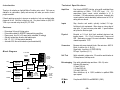
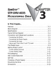
7/14/98
User's Manual
3540 M
Step Motor Driver
Applied Motion Products, Inc.
404 Westridge Drive • Watsonville, CA 95076
Tel (831) 761-6555
(800) 525-1609
Fax (831) 761-6544
motors • drives • controls
Technical Specifications
Introduction
Thank you for selecting an Applied Motion Products motor control. We hope our
dedication to performance, quality and economy will make your motion control
project successful.
If there's anything we can do to improve our products or help you use them better,
please call or fax. We'd like to hear from you. Our phone number is (800) 5251609 or you can reach us by fax at (831) 761-6544.
Amplifiers
Dual, bipolar MOSFET H-bridge, pulse width modulated three
state switching at 20kHz. 12-42 VDC input. 0.4 - 3.5
amps/phase output current, switch selectable in 0.1 A
increments. 122 watts maximum output power. Automatic idle
current reduction (switch selectable), reduces current to 50% of
setting after one second.
Inputs
Step, direction and enable, optically isolated, 5V logic.
5mA/signal, sink requirement. Motor steps on rising edge of
step input. 0.5 µsec minimum pulse width. 2 µsec minimum
set up time for direction signal.
Physical
Mounted on 1/4 inch thick black anodized aluminum heat
transfer chassis. 1.5 x 3.0 x 4.0 inches overall. Power on red
LED. See drawing on page 14 for more information. Maximum
chassis temperature: 70° C.
Connectors
European style screw terminal blocks. Max wire size: AWG 18.
Motor: 4 position (A+, A-, B+, B-)
Signal Input: 4 position (+5, STEP, DIR, EN)
DC Input: 2 position (V+, V-)
Self Test
Switch selectable, rotates motor 1/2 revolution each direction at
100 steps/second, half step mode.
Features
•
•
•
•
•
•
Drives sizes 14 through 34 step motors
Pulse width modulation, MOSFET 3 state switching amplifiers
Phase current from 0.4 to 3.5 amps (switch selectable, 32 settings)
Optically isolated step, direction and enable inputs
Half, 1/5, 1/10, 1/64 step (switch selectable)
Automatic 50% idle current reduction (can be switched off)
Block Diagram
12-42 VDC
self test
on/off
current
0.4 to 3.5
A/phase
5V
Reg
step
Optical
Isolator
Microstep
Sequencer
+5
direction
enable
Optical
Isolator
MOSFET
Amplifier
step
resolution
1/2, 1/5,
1/10 or 1/64
Optical
Isolator
A+
AB+
B-
to
motor
50% idle
current
reduction
on/off
Microstepping Four switch selectable step resolutions. With 1.8¡ motor:
Half step (400 steps/rev)
1/5 step (1000 s/r)
1/10 step (2000 s/r)
1/64 step (12,800 s/r)
Other resolutions, up to 12,800, available to qualified OEMs
upon request.
CE Mark
-2-
Complies with EN55011A and EN50082-1(1992).
-15-
Mechanical Outline
Getting Started
To use your Applied Motion Products motor control, you will need the following:
4x Ø.125
1.50"
0.125"
2.50"
2x Ø.125
3.70"
3.75"
4.00"
• a 12-42 volt DC power supply for the motor. Please read the section entitled
Choosing a Power Supply for help in choosing the right power supply.
• +5 volts DC, 15mA to activate the optoisolation circuits (if you don't use 5 volt
logic, see page 6.) This is provided by most indexers and PLCs.
• a source of step pulses capable of sinking at least 5 mA
• if your application calls for bidirectional rotation, you'll also need a
direction signal, capable of sinking 5 mA
• a compatible step motor
• a small flat blade screwdriver for tightening the connectors
The sketch below shows where to find the important connection and adjustment
points. Please examine it now.
0.25"
0.15"
3.00"
0.25"
power
connector
.875"
motor
connector
mounting
hole (1 of 6)
switches for
selecting current,
step resolution,
self test
-14-
logic
connector
(STEP, +5, DIR, EN)
-3-
Connecting the Power Supply
If you need information about choosing a power supply, please read Choosing a
Power Supply located on page 12 of this manual. The PS430 from Applied Motion
Products is a good supply for this drive.
Mounting the Drive
You can mount your drive on the wide or the narrow side of the chassis. If you
mount the drive on the wide side, use #4 screws through the four corner holes. For
narrow side mounting applications, you can use #4 screws in the two side holes.
If your power supply does not have a fuse on the output or some kind of short
circuit current limiting feature you need to put a 4 amp fast acting fuse between the
drive and power supply. Install the fuse on the + power supply lead.
smooth flat surface
Connect the motor power supply + terminal to the driver terminal labeled "+ VDC".
Connect power supply Ð to the drive terminal labeled "VDC Ð". Use no smaller
than 20 gauge wire. Be careful not to reverse the wires. Reverse connection
will destroy your driver, void your warranty and generally wreck your day.
fuse
+ VDC –
motor
+
supply
12-42 VDC –
wide side mount
Connecting the Motor
Warning: When connecting the motor to the driver, be sure that the
motor power supply is off. Secure any unused motor leads so that they
can't short out to anything. Never disconnect the motor while the drive
is powered up. Never connect motor leads to ground or to a power
supply!
You must now decide how to connect your
motor to the drive.
A+
Four lead motors can only be connected
one way. Please follow the sketch at the
right.
A–
Red
#4 screws
narrow side mount
The amplifiers in the drive generate heat. Unless you are running at 1 amp or
below, you may need a heat sink. To operate the drive continuously at maximum
power you must properly mount it on a heat sinking surface with a thermal constant
of no more than 4°C/watt. Applied Motion Products can provide a compatible heat
sink. Often, the metal enclosure of your system will make an effective heat sink.
Never use your drive in a space where there is no air flow or where other devices
cause the surrounding air to be more than 70 °C. Never put the drive where it can
get wet or where metal particles can get on it.
4
lead
motor
Blue
White
Yellow
Six lead motors can be connected in
B+
B–
series or center tap. In series mode, motors
produce more torque at low speeds, but
4 Leads
cannot run as fast as in the center tap configuration. In series operation, the motor
should be operated at 30% less than rated current to prevent overheating. Wiring
diagrams for both connection methods are shown on the next page. NC means not
connected to anything.
-4-
-13-
Choosing a Power Supply
Voltage
Chopper drives work by switching the voltage to the motor terminals on and off
while monitoring current to achieve a precise level of phase current. To do this
efficiently and silently, you'll want to have a power supply with a voltage rating at
least five times that of the motor. Depending on how fast you want to run the motor,
you may need even more voltage. More is better, the only upper limit being the
maximum voltage rating of the drive itself: 42 volts (including ripple).
If you choose an unregulated power supply, do not exceed 30 volts DC. This is
because unregulated supplies are rated at full load current. At lesser loads, like
when the motor is not moving, the actual voltage can be up to 1.4 times the voltage
list on the power supply label.
Current
The maximum supply current you will need is the sum of the two phase currents.
However, you will generally need a lot less than that, depending on the motor type,
voltage, speed and load conditions. That's because the 3540 M uses switching
amplifiers, converting a high voltage and low current into lower voltage and higher
current. The more the power supply voltage exceeds the motor voltage, the less
current you'll need from the power supply.
We recommend the following selection procedure:
1. If you plan to use only a few drives, get a power supply with at least twice the
rated phase current of the motor.
2. If you are designing for mass production and must minimize cost, get one
power supply with more than twice the rated current of the motor. Install the motor
in the application and monitor the current coming out of the power supply and into
the drive at various motor loads. This will tell you how much current you really
need so you can design in a lower cost power supply.
If you plan to use a regulated power supply you may encounter a problem with
current foldback. When you first power up your drive, the full current of both motor
phases will be drawn for a few milliseconds while the stator field is being
established. After that the amplifiers start chopping and much less current is drawn
from the power supply. If your power supply thinks this initial surge is a short
circuit it may "foldback" to a lower voltage. With many foldback schemes the
voltage returns to normal only after the first motor step and is fine thereafter. In that
sense, unregulated power supplies are better. They are also less expensive.
The PS430 from Applied Motion Products is a good supply to use with
the 3540 M.
-12-
Grn/Wht
A–
NC
A+
A–
6
lead
motor
White
Green
A+
NC
Red/
Wht
Red
B–
Black
NC
Grn/Wht
6
lead
motor
White
Green
Red/
Wht
Red
B–
B+
6 Leads Series Connected
Black
B+
NC
6 Leads Center Tap Connected
Eight lead motors can also be connected in two ways: series or parallel. As with
six lead motors, series operation gives you more torque at low speeds and less
torque at high speeds. In series operation, the motor should be operated at 30%
less than the rated current to prevent over heating. The wiring diagrams for eight
lead motors are shown below.
A+
Orange
Blk/Wht
Org/
Wht
A–
Black
Red
B+
Red/
Wht
Orange
Blk/Wht
8
lead
motor
Org/Wht
A–
A+
Yellow
Yel/
Wht B–
8
lead
motor
Black
Red
Yel/
B+ Wht
Yel
low
Red/Wht
B–
8 Leads Parallel Connected
8 Leads Series Connected
Connecting Logic
The 3540 M contains optical isolation circuitry to prevent the electrical noise
inherent in switching amplifiers from interfering with your circuits. Optical isolation
is accomplished by powering the motor driver from a different supply than your
circuits. There is no electrical connection between the two: signal communication
is achieved by infrared light. When your circuit is in the logic low state (near 0
volts), it is directing electrical current through an LED that is built into the drive.
The LED, in turn, produces infrared light which turns on a phototransistor that is
wired to the brains of the drive. When your circuit is in the logic high state, the LED
and phototransistor turn off.
-5-
Your drive is equipped with a feature that automatically reduces the motor current
by 50% anytime the motor is not moving. This reduces drive heating by about 50%
and lowers motor heating by 75%. This feature can be disabled if desired so that
full current is maintained at all times. This is useful when a high holding torque is
required. To minimize motor and drive heating we highly recommend that you
enable the idle current reduction feature unless your application strictly forbids it.
680
You must supply 5 volts DC to supply current to the LEDs on the input side of the
optoisolators. The maximum current draw is 15 mA total.
Your controlling logic must be capable of +5V
sinking at least 5 mA to control each drive
input. Most CMOS and open collector TTL
devices are directly compatible with this drive.
STEP
Logic low, or 0, for a given input occurs when
that input is pulled to less than 0.8 volts DC. DIR
In this state the LED is conducting current.
Logic high, or 1, occurs when the input is EN
Drive Input Circuit
greater than 4 volts or open.
680
Idle Current Reduction
680
A schematic diagram of the input circuit is shown below.
Idle current reduction is enabled by sliding switch #4 toward the 50% IDLE label,as
shown in the sketch below. Sliding the switch away from the 50% IDLE label
disables the reduction feature.
DIRECTION signals which way the motor should turn. See the step table on page 8
for details. The DIRECTION signal should be changed at least 2 microseconds
before a step pulse is sent. If you change the state of the direction input
and send a step pulse at the same instant the motor may take a step in
the wrong direction.
ENABLE allows the user to turn off the current to the motor by setting this signal to
logic 0. The logic circuitry continues to operate, so the drive "remembers" the step
position even when the amplifiers are disabled. However, the motor may move
slightly when the current is removed depending on the exact motor and load
characteristics. If you have no need to disable the amplifiers, you don't
need to connect anything to the ENABLE input.
Using Logic Voltages other than 5 volts DC
Self Test
The 3540 M includes a self test feature. This is used for trouble shooting. If you
are unsure about the motor or signal connections to the drive, or if the 3540 M isn't
responding to your step pulses, you can turn on the self test.
To activate the self test, slide switch #1 toward the TEST label. The drive will
slowly rotate the motor, 1/2 revolution forward, then 1/2 rev backward. The pattern
repeats until you slide the switch away from the TEST label. The 3540 M always
uses half step mode during the self test, no matter how you set switches 2 and 3.
The self test ignores the STEP and DIRECTION inputs while operating. The
ENABLE input continues to function normally.
TEST
TEST
Self Test ON
1
-6-
No Current Reduction
1
The 3540 M was designed to be used with 5 volt CMOS and TTL logic signals. To
prevent interference between the drive and the controlling logic, the input signals
are optically isolated. That means that your signals are powering LEDs within the
drive's optocoupler circuits. The LEDs require at least 5 milliamps of current to turn
on, but cannot stand more than 20 mA. Since the LEDs themselves only drop about
two volts, current limiting resistors must be used on each logic input.
Idle Current Reduction
Selected
4
STEP tells the driver when to move the motor one step. The drive steps on the
falling edge of the pulse. The minimum pulse width is 0.5 microseconds.
50% IDLE
4
50% IDLE
Self Test OFF
-11-
Microstepping
Most step motor drives offer a choice between full step and half step resolutions. In
most full step drives, both motor phases are used all the time. Half stepping divides
each step into two smaller steps by alternating between both phases on and one
phase on. Microstepping drives like the 3540 M precisely control the amount of
current in each phase at each step position as a means of electronically subdividing
the steps even further. The 3540 M offers a choice of half step and 3 microstep
resolutions. The highest setting divides each full step into 64 microsteps, providing
12,800 steps per revolution when using a 1.8˚ motor.
In addition to providing precise positioning and smooth motion, microstep drives
can be used to provide motion in convenient units. When the drive is set to 2000
steps/rev (1/10 step) and used with a 5 pitch lead screw, you get .0001 inches/step.
Please refer to the table below and set the switches for the resolution you want.
If your logic voltage is higher than five volts, you must add a resistor in series with
each signal that you use (STEP, DIR and EN). The recommended wiring diagram is
shown below. Table I lists the appropriate resistor value to use for a given power
supply voltage. 1/4 watt or larger resistors should be used.
Please take care not to reverse the wiring, as damage to the LEDs will
result rendering the drives inoperable. Check your wiring carefully
before turning on the power supply!
+V (12-42 volts DC)
R
INPUT SIGNALS
STEP
DIR
R
EN
R
STEP +5 DIR EN
Setting the step resolution is easy. Look at the dip switch on the 3540 M. Next to
switches 2 and 3, there are labels on the printed circuit board. Each switch has two
markings on each end. Switch 2 is marked 1/5, 1/10 at one end and 1/5, 1/64 at
the other. Switch 3 is labeled 1/2, 1/5 and 1/10, 1/64. To set the drive for a
resolution, push both switches toward the proper label. For example, if you want
1/10 step, push switch 2 toward the 1/10 label (to the left) and push switch 3 toward
1/10 (on the right).
We have included the proper resistor (680 ohms) within the drive for 5 volt
operation. Therefore, if your logic voltage is 5 volts, you do not need to add
resistors externally.
3540 M
drive
Note: DIR signal is only required for bidirectional motion.
EN signal is only required to shut off motor current.
Both inputs can be left open if not needed.
Table I: External Dropping Resistors
1/5
1/64
1/10
1/64
STEPS/REV
(1/10)
12800
STEPS/REV
(1/64)
-10-
1/2
1/10
1/5
1/2
1/2
1/10
1/5
1/2
1/5
1/64
1/10
1/64
2 3
1/2
1/10
1/5
1/2
2000
2 3
1000
STEPS/REV
(1/5)
1/5
1/64
1/10
1/64
2 3
STEPS/REV
(HALF)
1/2
1/10
1/5
1/2
2 3
400
1/5
1/64
1/10
1/64
Supply
Voltage
12
15
18
R
Ohms
1200
1800
2400
Supply
Voltage
21
24
27
-7-
R
Ohms
3000
3600
4200
Supply
Voltage
30
33
35
R
Ohms
4700
5100
5600
Current Setting Table
Step Table
(half stepping)
0.1
0.2
0.4
0.8
1.6
0.1
0.2
0.4
0.8
1.6
0.1
0.2
0.4
0.8
1.6
0.1
0.2
0.4
0.8
1.6
5 6 7 8 9
0.1
0.2
0.4
0.8
1.6
5 6 7 8 9
AMPS/
PHASE
0.1
0.2
0.4
0.8
1.6
5 6 7 8 9
5 6 7 8 9
3.0
5 6 7 8 9
0.1
0.2
0.4
0.8
1.6
AMPS/
PHASE
0.1
0.2
0.4
0.8
1.6
5 6 7 8 9
0.1
0.2
0.4
0.8
1.6
2.9
5 6 7 8 9
0.1
0.2
0.4
0.8
1.6
AMPS/
PHASE
0.1
0.2
0.4
0.8
1.6
5 6 7 8 9
0.1
0.2
0.4
0.8
1.6
2.8
5 6 7 8 9
0.1
0.2
0.4
0.8
1.6
5 6 7 8 9
AMPS/
PHASE
0.1
0.2
0.4
0.8
1.6
5 6 7 8 9
2.2
5 6 7 8 9
AMPS/
PHASE
0.1
0.2
0.4
0.8
1.6
5 6 7 8 9
0.1
0.2
0.4
0.8
1.6
2.1
5 6 7 8 9
0.1
0.2
0.4
0.8
1.6
AMPS/
PHASE
0.1
0.2
0.4
0.8
1.6
5 6 7 8 9
0.1
0.2
0.4
0.8
1.6
2.0
5 6 7 8 9
0.1
0.2
0.4
0.8
1.6
0.1
0.2
0.4
0.8
1.6
5 6 7 8 9
0.1
0.2
0.4
0.8
1.6
0.1
0.2
0.4
0.8
1.6
5 6 7 8 9
0.1
0.2
0.4
0.8
1.6
AMPS/
PHASE
0.1
0.2
0.4
0.8
1.6
5 6 7 8 9
0.1
0.2
0.4
0.8
1.6
1.4
5 6 7 8 9
0.1
0.2
0.4
0.8
1.6
AMPS/
PHASE
0.1
0.2
0.4
0.8
1.6
5 6 7 8 9
AMPS/
PHASE
0.1
0.2
0.4
0.8
1.6
1.3
5 6 7 8 9
0.6
AMPS/
PHASE
0.1
0.2
0.4
0.8
1.6
5 6 7 8 9
AMPS/
PHASE
0.1
0.2
0.4
0.8
1.6
1.2
5 6 7 8 9
0.5
5 6 7 8 9
DIR=0
ccw
5 6 7 8 9
AMPS/
PHASE
0.1
0.2
0.4
0.8
1.6
5 6 7 8 9
0.4
5 6 7 8 9
B–
–
open
+
+
+
open
–
–
5 6 7 8 9
B+
+
+
open
–
–
–
open
+
+
5 6 7 8 9
Aopen
–
–
–
open
+
+
+
open
5 6 7 8 9
A+
open
+
+
+
open
–
–
–
open
5 6 7 8 9
DIR=1
cw
Step
0
1
2
3
4
5
6
7
8
Step 0 is the Power Up State
Setting Phase Current
0.7
Before you turn on the power supply the first time, you need to set the driver for the
proper motor phase current. The rated current is usually printed on the motor label.
The 3540 M drive current is easy to set. If you wish, you can learn a simple formula
for setting current and never need the manual again. Or you can skip to the table on
the next page, find the current setting you want, and set the DIP switches according
to the picture.
AMPS/
PHASE
Current Setting Formula
Locate the bank of tiny switches near the motor connector. Four of the switches
have a value of current printed next to them, such as 0.4 and 0.8. Each switch
controls the amount of current, in amperes (A), that its label indicates. There is
always a base of current of 0.4 A. To add to that, slide the appropriate switches
toward their labels on the PC board. You may need your small screwdriver for this.
-8-
AMPS/
PHASE
0.9
AMPS/
PHASE
1.0
AMPS/
PHASE
0.1
0.2
0.4
0.8
1.6
5 6 7 8 9
Example
Suppose you want to set the driver for 2.2 amps per
phase. You need the 0.4 A base current plus another 1.6
and 0.2 A.
2.2 = 0.4 + 1.6 + 0.2
Slide the 1.6 and 0.2 A switches toward the labels as
shown in the figure.
0.8
1.1
AMPS/
PHASE
1.5
AMPS/
PHASE
1.6
AMPS/
PHASE
1.7
AMPS/
PHASE
1.8
AMPS/
PHASE
1.9
AMPS/
PHASE
-9-
2.3
AMPS/
PHASE
2.4
AMPS/
PHASE
2.5
AMPS/
PHASE
2.6
AMPS/
PHASE
2.7
AMPS/
PHASE
3.1
AMPS/
PHASE
3.2
AMPS/
PHASE
3.3
AMPS/
PHASE
3.4
AMPS/
PHASE
3.5
AMPS/
PHASE