1
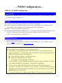
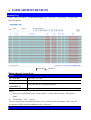
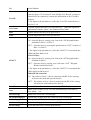
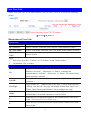
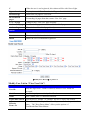
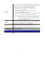
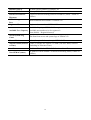
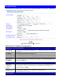
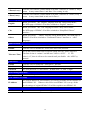
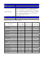
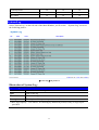
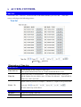
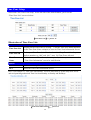
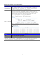
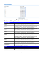
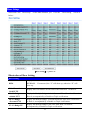
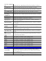
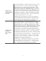
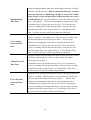
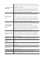
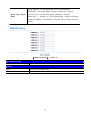
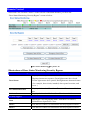
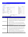
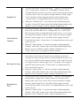
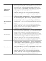
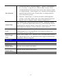
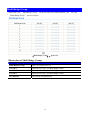
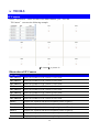
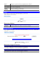
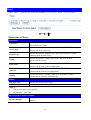
SEMAC-S2 WEB Configuration Manual For SEMAC item only: 0.10.00, Aug 24 2009(HW1.0) SEMAC Web Ver1.4 Build Date 08/18/2009 Revision History 2009/08/26 1. Newly added Administrator Password (P.13) 2. Newly added Event Type : 『Alarm』and『IP Camera』P31 3. Newly added E-mail Alart :『Mail from』、『SMTP Server』、『Mail to』、『Mail copy』 4. Newly added IP Camera:『PORT』 and『TYPE』 Reversion History Contents WEB CONFIGURATION ............................................................................................................................................... 1 LOGON WEB....................................................................................................................................................................... 1 PREMISE .............................................................................................................................................................................. 1 WEB IE BROWSER .............................................................................................................................................................. 1 MAIN WINDOW (TERMINAL STATUS)..................................................................................................................... 2 DOOR SETUP & BF-50 STATUS – MONITORING PANEL ...................................................................................................... 3 USER ADMINISTRATION............................................................................................................................................. 4 ACCESS LOG ........................................................................................................................................................................ 4 VIEW USER LIST .................................................................................................................................................................. 6 ADD USER ........................................................................................................................................................................... 9 TERMINAL .................................................................................................................................................................... 11 TERMINAL STATUS ............................................................................................................................................................. 11 TERMINAL SETUP .............................................................................................................................................................. 13 PASSWORD SETUP .............................................................................................................................................................. 15 SYSTEM LOG ..................................................................................................................................................................... 17 CLOCK SETUP .................................................................................................................................................................... 18 ACCESS CONTROL ..................................................................................................................................................... 19 TIME SET ........................................................................................................................................................................... 19 TIME ZONE SETUP ............................................................................................................................................................. 20 GROUP LIST ....................................................................................................................................................................... 22 HOLIDAY SETUP ................................................................................................................................................................ 24 DOOR SETUP...................................................................................................................................................................... 25 REMOTE CONTROL ............................................................................................................................................................ 32 EVENT HANDLE ................................................................................................................................................................. 34 MULTI BADGE GROUP ....................................................................................................................................................... 39 TOOLS ............................................................................................................................................................................ 40 IP CAMERA ........................................................................................................................................................................ 40 REBOOT ............................................................................................................................................................................. 41 UPGRADE FIRMWARE ........................................................................................................................................................ 41 RESET ................................................................................................................................................................................ 42 Copyright @ 2009. All Rights Reserved. Document Version: 1.0 All trademarks and trade names are the properties of their respective owners. Contents-1 -WEB Configuration- SEMAC-S2 WEB Configuration Logon WEB SEMAC-S2 is with built-in HTTP server for using WEB IE Browser to connect SEMAC-S2 and execute the settings of SEMAC-S2. Premise Please make sure the following points before your SEMAC-S2 settings: z Your PC computer may build up a physical connection with SEMAC-S2, meanwhile, both of your computer and the SEMAC-S2 are within the same Network Segment. z SEMAC-S2 has been installed and with power. z Should the default IP address of SEMAC-S2(192.168.0.66)has been occupied by other devices, you have to shut down all the other devices until the setting completed. Then a new IP address will be distributed to the SEMAC-S2. WEB IE Browser 1. Start the WEB IE Browser first. 2. Enter the http:// and the IP address of SEMAC-S2 in the address bar. default IP address of SEMAC-S2: http://192.168.0.66. For example, enter the Communication failure: When no feedback from the SEMAC-S2, please check as below: z Is the SEMAC-S2 installed properly, the local area network (LAN) connected well or the power connected fine? Try to use the “ping” command to test the communication status of SEMAC-S2 IP address by the following steps: Open a MS-DOS window, or a command window; Input your command: ping 192.168.0.66, For example : C:\user\tank>ping 192.168.0.66 If no any response, it means abnormal connection or the PC computer IP address in conflict or not match with SEMAC-S2 IP address(referring to next paragraph). z If a PC computer with a Static IP/Fixed IP, the IP range should be defined between 192.168.0.1~ 192.168.0.65 or 192.168.0.67~192.168.0.254. So the PC computer IP may be compatible with the default IP address of SEMAC-S2, 192.168.0.66. Moreover, the Subnet Mask should be as 255.255.255.0。 z To make sure both your PC computer and the SEMAC-S2 in the same Network Segment. 1 ¾ MAIN WINDOW (TERMINAL STATUS) When installation completed and well connected with SEMAC-S2, the “MAIN WINDOW” will will pop up. It will show after the following connection frequently as following illustration : 【Main Window】- picture 1 Illustration of Terminal Status: z Browse the Function Menu Bar at the left side of the Main Window by IE Browser. USER ADMINISTRATION Access Log View User List Add User Switch to the “Access Log” screen. Switch to the “User List" screen to Modify, Delete, Deactivate and Activate the data. Switch to the “User RECORD" screen and “Add New User". TERMINAL Terminal Status Switch to the “Terminal Status" screen ( Main Window) Terminal Setup Switch to the “Terminal Setup" screen. Password Setup Switch to the “WEB Logon Setting” and “Entrance Password” screen. System Log Switch to the “System Log” screen. Clock Setup Switch to the “SYSTEM CLOCK SETUP” screen. 2 ACCESS CONTROL Time Set Switch to the “Time Set” screen. Time Zone Setup Switch to the “Time Zone List” screen. Group List Switch to the “Group List” screen. Holiday Setup Switch to the “Holiday Setup” screen. Door Setup Switch to the “Door Setting” screen. Remote Control Switch to the “Door Status Monitoring” and “Security Bypass” screen. Event Handle Switch to the “Event Handle” screen. Multi Badge Group Switch to the “Multi Badge Group” screen. TOOLS IP Camera Switch to the “IP Camera Configuration“ screen. Reboot Switch to the “Reboot System“ screen. Upgrade Firmware Switch to the “Firmware Upgrade“ screen. Reset Switch to the “Reset“ screen. BUTTON Refresh Refresh the WEB Status. Door Setup & BF-50 STATUS – Monitoring Panel The Main Window will show you the monitored Real Time Door Setup and BF-50 status of SEMAC-S2 automatically , referring to the following: Illustration of Door Setup & BF-50 Status Steps 1. Click the “START" button on the panel to refresh the door and BF-50 status continually. 2. Indicators of the Door Status: Green Light : Door Closes Yellow Light: Door Opens Grey Light : No Response Red Light : Abnormal Status “X" : Not Available 3. BF-50 has two statuses as “V" and “X",“V"= BF-50 detected and otherwise “X 4. 5. Whenever you flash your card thru reader, the User ID, Date, Time, IN/OUT and Door Number will be showed on the right place of the panel. Click the “STOP” button again to stop the refresh action. 3 ¾ USER ADMINISTRATION Access Log Select"Access Control" on the Main Window, you'll see the “Access Log" screen as the following picture: 【Access Log】- picture 2 Illustration of Access Log: Query By “User ID” Enter the “User ID”. By “Card No.” Enter the “Card No.”. By ”From/To” ( MM/DD/YY) Select the date by “Drop Down Menu”. Click Start to search. button “GO” Steps : 1. Enter your requirements in the “blank textbox” or Select them from the “Drop Down Menu". 2. Click button “GO" to query. We are using the inter-searching formula to sieve out the queried information. Thus, only the records meet all the selected conditions will be listed out. Access Records Illustration by Columns 4 No. Serial Number User ID An ID registered for the User to get IN/OUT. Click the “User ID”to enter the page of “User Record” and “Modify User Record” (picture 4). Should it be not connected, it means the information of the User ID is deleted. * The figure in the parentheses ( ) after the “User ID” means the user’s level as 1~10. User Name A Name registered for the User to get IN/OUT. When the registered information without “Name”, this column will be blank. Date A Date allowed for the User to get IN/OUT. Time A Time allowed for the User to get IN/OUT. 2 Door/1 Way: IN:Open the door by sensing your Card at the “IN”Wiegand Reader installed for Door 1 or Door 2. OUT:Open the door by pressing the push button at “OUT” location of Door 1 or Door 2. * The figure in the parentheses ( ) after the “IN/OUT” record means the APB(Anti Pass Back) level. 1 Door/2 Way: IN:Open the door by sensing your Card at the “IN”Wiegand Reader IN/OUT installed for Door 1. OUT:Open the door by sensing your Card at the “OUT” Wiegand Reader installed for Door 1. * The figure in the parentheses ( ) after the “IN/OUT” record means the APB (Anti Pass Back) level. When BF-50 connected: IN:The readers of door 3~door 8 connected with BF-50 for entering will sense the cards and open the door(s). OUT:The readers of door 3~door 8 connected with BF-50 for exiting will sense the cards and open the door(s). Door No. It stands for the Door Number controlled by SEMAC-S2. Note Show up the relative IN/OUT records automatically as Anti-Duress, Fire Alarm......etc. the First Page Back to the 1st IN/OUT records page. the Former10 pages Forwarding 10 pages from the current IN/OUT records page. 1 2 3…N page Change to any IN/OUT records page assigned. the Latter 10 pages Backwards 10 pages from the current IN/OUT records page. the Last Page Fly to the last IN/OUT records page directly. 5 View User List Select”View User List” on the Main Window, you’ll see the “User List” screen as the following picture: 【User List】- picture 3 Illustration of User List: Search User By “User ID” Select “User ID”and Enter your “User ID”in the textbox to search. By “Card No.” Select “Card No.”and Enter your“Card No.”in the textbox to search. By “User Name” Select “User Name.”and Enter your“User Name”in the textbox to search. Click button “GO” Start to search. Steps : 1. Enter your “User ID”, “Card No.” or “User Name” in the “blank textbox”. 2. Click button “GO” to search. User List No. Serial Number. Tick the box before the “Serial Number” and Click the button of “Activate” , “Deactivate” or “Delete” to manage the authorization of “Activate” , “Deactivate” or “Delete” for selected users, multi-selection is allowed. User ID User’s ID. Click the “User ID” to enter the “Modify User Record” page (picture 4 ). User Type Types of the User. Whenever the “User Type” is set up in the screen of “Modify User Record”, this page will display Normal User, Super User, Visitor, Guard Touring and Defense Card according to the setup. Active Display the user’s authorization status. Green Light means the user’s authorization is Activated, otherwise it is not activated. F When the user’s Fingerprint registered, this column will be with Green Light. (This function is not available now.) P When the user’s Personal Password registered, this column will be with Green Light. 6 C When the user’s card registered, this column will be with Green Light. Bypass Level Display the user’s Time Zone level of Bypass from L1~L10. the First Page Back to the 1st page of “User List”. the Former10 pages Forwarding 10 pages from the current “User List” page. 1 2 3…N page Change to any “User List” page assigned. the Latter 10 pages Backwards 10 pages from the current “User List” page. the Last Page Fly to the last “User List” page directly. Button Activate Activate the User’s authorization. Deactivate Deactivate the User’s authorization. Delete Delete the User’s information registered. 【Modify User Record】- picture 4 Modify User List in “View User List”: User Record User ID Only the digit from 1~20000 is allowed, whenever over 20000 not accepted. Card No. It can be input by manual or by Card Reader. Name User’s Name, max. 31 characters allowed. Expire Date Check Tick the box of “Enable” or “Disable” the user’s expiry date control. Effective From ~To When “Enable” the “Expire Date Check”, you must enter the period of dates. The” Drop Down Menu” offers you the options of Year/Month/Date/Hour/Minute. 7 Status Tick the box of “Activate” or “Deactivate” for an authorization to the user. Card Types of the User. The “Drop Down Menu” will list out cards for Normal User , Super User, Visitor, Guard Touring and Defense Card as your choice. The Respective definitions are as below : Super User Card : Not constrained by the limitation of APB ( Anti Pass Back). User Type Visitor Card : You may manage the visitors easily by setting the Visitor Card’s Expiry Dates. Guard Touring: When the Guard Touring card senses the door, only the Logs will be kept but no door-open function. Defense Card: When the card sweeps the door, all the doors will activate Access Control at once. Any type of card cannot open the door until the Defense Card sweeps the door again to restore normal functions. Group Each user can be assigned to 4 different groups. All of the group names existed will be automatically listed out by the “Drop Down Menu” for your choice. “Free Time Group” is a “Default Group”. Bypass TZ Level The “Bypass Time Zone Level” of each user is from L1~L10. Whenever the user’s “Bypass Time Zone Level” is higher than or equal to the door’s level, the door’s “Bypass Time Zone”becomes invalid. Personal Password 4~8 digits are required. Personal Confirm Reconfirm Personal Password. Button previous Modify previous user record. save Save the modified user record. delete Delete existing user record. next Modify next user record. 8 Add User Select”Add User” on the Main Window, you’ll see the User Record ” screen for Add New User as the following picture: 【Add New User】- picture 5 Illustration of Add New User: User RECORD REG Single: Only one user can be registered each time. Continuous: It allows you to register 1~20000 users continually. You may input required q’ty in the textbox of Amount. However, only the serial number is accepted and supported. User ID Only the digit from 1~20000 is allowed, whenever over 20000 not accepted. Card No. It can be input by manual or by Card Reader. Name User’s Name, max. 31 characters allowed. Expire Date Check Tick the box of “Enable” or “Disable” the user’s expiry date control. Effective From ~To When “Enable” the “Expire Date Check”, you must enter the period of dates. The” Drop Down Menu” offers options of Year/Month/Date/Hour/Minute. Status Tick the box of “Activate” or “Deactivate” for an authorization to the user. 9 Card Types of the User. The “Drop Down Menu” will list out cards for Normal User, Super User, Visitor, Guard Touring and Defense Card as your choice. The Respective definitions are as below : Super User Card: Not constrained by the limitation of APB ( Anti Pass Back). User Type Visitor Card: You may manage the visitors easily by setting the Visitor Card’s Expiry Dates. Guard Touring: When the Guard Touring card senses the door, only the Logs will be kept but no door-open function. Defense Card: When the card sweeps the door, all the doors will activate Access Control at once. Any type of card cannot open the door until the Defense Card sweeps the door again to restore normal functions. Group Each user can be assigned to 4 different groups. All of the group names existed will be automatically listed out by the “Drop Down Menu” for your choice. “Free Time Group” is a “Default Group”. Bypass TZ Level The “Bypass Time Zone Level” of each user is from L1~L10. Whenever the user’s “Bypass Time Zone Level” is higher than or equal to the door’s level, the door’s “Bypass Time Zone”becomes invalid. Personal Password 4~8 digits are required. Personal Confirm Button Reconfirm Personal Password. save Save user records. 10 ¾ TERMINAL Terminal Status Select and Click”Terminal Status” on the left side of the Main Window, you’ll see the “Terminal Status” screen. This screen is the Main Window for Logon. It displays the current Terminal Status and relative information of WEB setup, referring to the following picture: 【Terminal Status】- picture 6 Illustration of TERMINAL STATUS: TERMINAL STATUS Product Name Model Number of SEMAC-S2 Serial No. Serial Number of SEMAC-S2 Firmware Version Firmware and Hardware Version of SEMAC-S2 System Time System Time of SEMAC-S2 Terminal ID (MAC Address) Terminal ID and MAC address of SEMAC-S2 IP Address IP address of SECMAC-S2 Subnet mask Subnet mask of SEMAC-S2 11 Default Gateway Default Gateway address of SEMAC-S2 Primary DNS Primary DNS address of SEMAC-S2 Listen Port/Software IP(status) Listen Port and Networking Software IP address ( status : Online or Offline) WEB Management Port WEB communication number of SEMAC-S2 Registered User Registered user number of SEMAC-S2 Available Capacity of SEMAC-S2 to register users; Available User Capacity Available user number(s) to be registered= Sum (20000)-Registered user(s) Access/System Log Count The Sum from access and system logs of SEMAC-S2 Control Mode 1 door(2 way) or 2 doors (1 way) of SEMAC-S2 Anti-Pass-Back(Toleran Enable or Disable the SEMAC-S2 APB (Anti Pass Back) function (including its Tolerance Time). ce Time) Anti-Duress Enable or Disable the SEMAC-S2 function of Anti Duress. Next SEMAC(status) IP Address of Next SEMAC-S2 and its networking status ( Online or Offline) 12 Terminal Setup Select and Click”Terminal Setup” on the left side of the Main Window, you’ll see the “TERMINAL CONFIGURATION”, referring to the following picture: 【Terminal Configuration】- picture 7 Illustration of Terminal Configuration: TERMINAL CONFIGURATION Terminal ID For setting the Terminal ID of SEMAC-S2. Default ID=1, max. 65535, no ID duplicated. IP Address For setting the IP Address of SEMAC-S2. Subnet Mask For setting the Subnet Mask of SEMAC-S2 Gateway For setting the Default Gateway of SEMAC-S2 DNS Server IP Address For setting the DNS Server IP Address of SEMAC-S2. Default DNS Server IP Address is 168.95.1.1. Software TCP Port ( Software Used) Software IP For setting the TCP Port of the Software to communicate with SEMAC-S2. Default TCP Port is 2000. For setting the Software IP to communicate with SEMAC-S2 Default Software IP is 0.0.0.0. Control Mode 13 2 Doors(1 way) Tick this circle and the Control Mode of SEMAC-S2will be as 2 Doors (1 way ) status. It may control Door 1 and Door 2 for coming in only. 1 Door(2 way) Tick this circle and the Control Mode of SEMAC-S2will be as 1 Door (2 way ) status. It may control both in and out for Door 1. Web Language English When you choose the” English” language from the “Drop Down Menu”, the WEB page of SEMAC-S2 will be switched to “English” interface . Chs When you choose the” Chs” language from the “Drop Down Menu”, the WEB page of SEMAC-S2 will be switched to “Simplified Chinese” interface . Others When you choose ” Others” from the “Drop Down Menu”, the WEB page of SEMAC-S2 will be switched to “Traditional Chinese” interface or other languages. Anti Pass Back Enable Tick this circle to enable the “APB”(Anti Pass Pack) function. Disable Tick this circle to disable the “APB”(Anti Pass Pack) function. Tolerance Time Set up the restored time back to original setting after the “APB” triggered. The unit of time is “minute” and the max. Value is “65535”. If the value is “0”, then it will never be restored until you disable the “APB” by manual. Anti Duress Enable Tick this circle to enable the “Anti Duress” function. Disable Tick this circle to disable the “Anti Duress”function. Password Set your password of “Anti Duress”, default value = 9, max. 3 digits. WEB Management Port Http Port Set your WEB port for SEMAC-S2, default value=80. Next SEMAC( for APB) IP Address Set your IP address for Next SEMAC-S2, but only available for the structure of multi SEMAC-S2. Whenever this IP for next SEMAC-S2 is set up, all the levels settings of original SEMAC-S2 will be copied to next SEMAC-S2. Button SAVE Save the Terminal configuration settings. 14 Password Setup Select ”Password Setup” on the left side of the Main Window, you’ll see the “WEB Logon Setting/Entrance Password”screen, referring to the following picture: 【WEB Logon Setting/Entrance Password】- picture 8 Illustration of WEB Logon Setting/Entrance Password: WEB Logon Setting Administrator WEB Logon User Name Input the required Administrator’s logon user name for WEB management, max. 47 characters, default value: “admin”. Administrator WEB Logon Password Input the required Administrator’s logon password for WEB management, max. 35 digits, default value: “admin”. Operator WEB Logon User Name Input the required Operator’s logon user name for WEB management, max. 47 characters, default value: “user”. Operator WEB Logon Password Input the required Operator’s logon password for WEB management, max. 35 digits, default value: “user”. User WEB Logon User Name Input the required User’s logon user name for WEB management, max. 47 characters, default value: “user0”. User WEB Logon Password Input the required User’s logon user name for WEB management, max. 35 digits, default value: “user0”. The Administrator, Operator and User have their respective authorizations, referring to the following “Authorization Table”. 15 Button Save all the WEB Logon Settings. SAVE Entrance Password Common Password Set your “Common Password” here. Meanwhile, you have to select “001 Any Time ”for “Common Password Time Zone “ simultaneously to support this setting ( for example: Door Setup ÆDoor SettingÆClick “Door1”Æ Door 1 SettingÆ Select “Common Password Time Zone “Æ Select “001 Any Time “from the “Drop Down Menu”). Default value: “1234”. Button Save the Password setting. SAVE Authorizations Table (“●” = Access Permission) WEB Function Administrator User Name: admin Password : admin Operator User Name: user Password : user User User Name: user0 Password Upgrade Firmware ● Password Setup ● Terminal Setup ● Door Setup ● Event Handle ● Reboot ● Clock Setup ● Reset ● Upgrade Firmware ● Password Setup ● Terminal Setup ● User Data ● ● Time Set ● ● Time Zone Setup ● ● Group List ● ● Holiday Setup ● ● Lift Setup ● ● Multi Badge Group ● ● Remote Control ● ● Access Log ● ● ● View User List ● ● ● 16 : user0 Terminal Status ● ● ● System Log ● ● ● IP Camera ● ● ● System Log Select”System Log” on the left side of the Main Window, you’ll see the “System Log ”screen as the following picture: 【System Log】- picture 9 Illustration of System Log: System Log No. Serial Number of the log Date Date of the log Time Time of the log Description Description of the system operation records * Max. logs capacity : 1536 entries, for checking by authorized person(s) only, no logs export provided. 17 Clock Setup Select and Click "Clock Setup" on the left side of the Main Window, you'll see the “SYSTEM CLOCK SETUP" screen, referring to the following picture: 【SYSTEM CLOCK SETUP】- picture 10 Illustration of System Clock Setup: Time Server Disable Tick this circle to shut up the Time Server network connection. Enable Tick this circle to start the Time Server network connection. Time Zone The “Drop Down Menu” offers you all the Time Zones available up to your option, default time zone : (GMT)England. “SAVE” button Save the Time Server Settings and adjust the time. When enable the “Time Server”, please key in the IP address or http:// of the “Time Server”. Then select the required Time Zone and Save it to connect the “Time Server” for a time adjustment. New Date New Time “SAVE” button The date of networked PC computer. You may adjust the date to your requirement as the format of “mm/dd/yyyy”. The date of networked PC computer. You may adjust the time to your requirement as the format of “hh:mm:ss”. Save the configuration of this page and upgrade the date/time for the networked PC computer. 18 ¾ ACCESS CONTROL Time Set Select and Click “ Time Set ” on the left side of the Main Window, you’ll see the “Time Set” screen, referring to the following picture: 【Time Set】- picture 11 Illustration of Time Set: Time Set List Time Set List It will display all the configured time set(s). The System Default Time sets are: 00:00~00:00 and 00:00~23:59. Time Set Select your time set serial number. The “Drop Down Menu” offers you all the options for your choice, max. 255 time sets allowed. System built-in values are “000” and “001”. Input a time set period, for example : 8:00am to 17:00pm as one period, then From ~ To It is the same way to the others. Button DELETE Delete an existing “Time Set”. SET Add a new “Time Set”. 19 Time Zone Setup Select and Click”Time Zone Setup” on the left side of the Main Window, you’ll see the “Time Zone List” screen as below: 【Time Zone List】- picture 12 Illustration of Time Zone List: Time Zone List Time Zone List Display all the Time Zone(s) existing. Click the Time Zone name(indicated as the Time Zone Name example) to enter its Time Zone Information Screen. Time Zone ID Select your Time Zone Serial Number from the “Drop Down Menu”, system built-in numbers as “000” and “001”, max. 120 Time Zones allowed. Time Zone Name Click the name of Time Zone ( for example : 2, as below picture) to enter the ”Time Zone Information” screen for modification. Button DELETE Delete an existing Time Zone. SET Enter the Time Zone Information screen. Here is an example of “Time Zone Information” screen to show how to set the daily door access and card punching authorized Time Set from Monday to Sunday and Holidays: 【Time Zone Information】- picture 13 20 Illustration of Time Zone Information Time Zone Information Settings Weekday (Day) The “Drop Down Menu ”offers options from Monday to Sunday and Holiday. Steps:“SET”the Time Set on Time Set” screenÆ Select a weekday ÆChoose your time set(s) of the time zones. Each day from Monday ~Sunday and Holiday is allowed 16 time sets. However, you have to make some Time Sets on the “Time Set” screen in advance for the options here, otherwise only 2 default Time sets for your choice, referring to the following illustration: Step 1 : “Time Set” screen to “SET” some time sets Time 1 ~ Time16 Step 2 : “Time Zone Information” screen for more options than original 2 default time sets Button Save Save the“Time Zone Information”. Cancel Cancel or Modify the “Time Zone Information”. When the “ Time Zone Setup “ completed, please click the “Time Zone Name ”to enter its “Time Zone Information”screen and see the list with all of its time sets as picture 13. 21 Group List Select”Group List” on the left side of the Main Window, you’ll see the “Group List” screen as below: 【Group List】- picture 14 Illustration of Group List: Group List Display all the Groups configured. Click the Group’s name to enter its “Group Information ”as below : (for example: click Group Name”4” as picture 14) Group List Select your “Group ID” by serial number, default values : 000、001. Group ID The ”Drop Down Menu ”offers you all the serial number of Group ID as options, max. 255 groups allowed. Button DELETE Delete a Group ID. SET Enter the “Group Information” screen. This is a screen to configure the door(s) of a Group ID, referring to the following picture: 22 【Group Information】- picture 15 Illustration of Group Information: Allowed Door Door 1 Tick the box of Door 1, then the user(s) of this Group can access Door 1 within the “Time Zone ID”, otherwise prohibited. Door 2 Tick the box of Door 2, then the user(s) of this Group can access Door 2 within the “Time Zone ID”, otherwise prohibited. Door 3 Tick the box of Door 3, then the user(s) of this Group can access Door 3 within the “Time Zone ID”, otherwise prohibited. Door 4 Tick the box of Door 4, then the user(s) of this Group can access Door 4 within the “Time Zone ID”, otherwise prohibited. Door 5 Tick the box of Door 5, then the user(s) of this Group can access Door 5 within the “Time Zone ID”, otherwise prohibited. Door 6 Tick the box of Door 6, then the user(s) of this Group can access Door 6 within the “Time Zone ID”, otherwise prohibited. Door 7 Tick the box of Door 7, then the user(s) of this Group can access Door 7 within the “Time Zone ID”, otherwise prohibited. Door 8 Tick the box of Door 8, then the user(s) of this Group can access Door 8 within the “Time Zone ID”, otherwise prohibited. Tim Zone ID The“Drop Down Menu”displays all the “Time Zones” configured in the “Time Zone Setup”for your choice. Button SAVE Save the “Group Information”. CANCEL Cancel or Modify the “Group Information” 23 Holiday Setup Select”Holiday Setup” on the left side of the Main Window, you’ll see the “Holiday setup” screen as below: 【Holiday Setup】- picture 16 Illustration of Holiday Setup Holiday Setup Month Select a month from the “Drop Down Menu". Date Select a date from the “Drop Down Menu". Button SET Add a new Holiday. DELETE Delete a Holiday. 24 Door Setup Select and Click"Door Setup" on the Main Window, you'll see the “Door setting" screen as below: 【Door Setting】- picture 17 Illustration of Door Setting Door Setting BF50 Display the connection status from Door 1~ Door 8 with BF50/ WEBPASS. If connected, the “V” will show up, otherwise “X” will show up. L10 : First Admin Card IN TZ Display the First Admin Card IN Time Zone from Door 1 to Door 8. L9: 2/3 Badge +Admin P TZ Display the Multiple Badge+ Admin Password Time Zone from Door 1 to Door 8, accompanied by a Double or Triple verifications. L8: 2/3 Badge +Personal P TZ Display the Multiple Badge +Personal Password Time Zone from Door 1 to Door 8, accompanied by a Double or Triple verifications. L7: 2/3 Badge TZ Display the Multiple Badge Time Zone from Door 1 to Door 8, accompanied by a Double or Triple verifications. 25 L6: Card + Admin P TZ Display the Card +Admin Password Time Zone from Door 1 to Door 8. L5: Admin P TZ Display the Admin Password Time Zone from Door 1 to Door 8. L4: Card + Personal TZ Display the Card +Personal Password Time Zone from Door 1 to Door 8. L3: Common P TZ Display the Common Password Time Zone from Door 1 to Door 8. L2: Card Only TZ Display the Card Only Time Zone from Door 1 to Door 8. L1: Card or Common TZ Display the Card or Common Password Time Zone from Door 1 to Door 8. Lock Release TZ Display the Lock Release Time Zone from Door 1 to Door 8. Exit Button TZ Display the Exit Button TZ from Door 1 to Door 8. APB IN/OUT Display the Anti Pass Back Level from Door 1 to Door 8, APB level : 0-255 for door IN/OUT. Dual Interlocking Display the Dual Interlocking function from Door 1 to Door 8, “Enabled” or “Disabled”. Remote Grant Needed Display the Remote Grant function from Door 1 to Door 8, “Enabled” or “Disabled”. Lock Release Time Display the Lock Release Time from Door 1 to Door 8, 1 – 65535 seconds allowed and 10 seconds = default. Open Delay Time Display the Door Open Delay Time from Door 1 to Door 8, 10 seconds = default. Log Recorded/Sensor Mode Display the Access Log to be Recorded or Ignored from Door 1 to Door 8, and the Door Sensor Mode. Door 1 Click “Door 1” to enter the “ Door 1 Setting” screen. Door 2 Click “Door 2” to enter the “ Door 2 Setting” screen. Door 3 Click “Door 3” to enter the “ Door 3 Setting” screen. Door 4 Click “Door 4” to enter the “ Door 4 Setting” screen. Door 5 Click “Door 5” to enter the “ Door 5 Setting” screen. Door 6 Click “Door 6” to enter the “ Door 6 Setting” screen. Door 7 Click “Door 7” to enter the “ Door 7 Setting” screen. Door 8 Click “Door 8” to enter the “ Door 8 Setting” screen. Button Search BF50 Click button “Search BF50” to detect each BF50 of Door 1~Door 8. Whenever BF50 connected and detected, the column of BF50 will show up “V” otherwise “X”. Save BF50 Click button “Search BF50” to save all the BF50 statuses. Set WEBPASS Click button “Set WEBPASS” to configure the WEB PASS IP address. 26 【Door 1 Setting】- picture 18 Illustrations of Door 1 Setting in Door Setup Door 1 Setting First Admin Card IN Time Zone Set up the time zone of First Administrator’s Card to open the door as the bypass time zone of Door 1 ( default– “000 Deactivate“). When this time zone is chosen, the user can only use the card of Administrator to scan/sweep the controller first and the other users may enter Door 1. Nobody may enter without using this First Admin Card to scan the controller of Door 1 in advance. * Should the user’s bypass time zone level is L10, he/she may access by scanning the card and enter the Door 1 directly; however when the bypass time zone setup of Door 1 is“ Lock Release Time Zone “, the user may access directly without any limitation. 27 Set up the Multiple Badge + Administrator Password time zone as the bypass time zone of Door 1 ( default– “000 Deactivate“). Before Multiple Badge +Admin Password Time Zone setting this time zone, you must choose the function of “ Multi Badge Group ”to come to the “Multi Badge Group ” screen and give the user ID in this time zone, max. 3 user IDs allowed; the user needs both 2 or 3 user ID cards and the Administrator’s password to enter the Door 1 successfully. No any order limitation for scanning the cards first or enter the password first. You may scan the cards first then enter the password, or in reverse order. * Should the user’s bypass time zone level is L9~L10, he/she may access by scanning the card and enter the Door 1 directly; however when the bypass time zone setup of Door 1 is“ Lock Release Time Zone “, the user may access directly without any limitation. Set up the Multiple Badge + Personal Password time zone as the bypass time zone of Door 1 ( default–000 Deactivate“). Before setting this time zone, you must choose the function of “Multi Badge Group"to come to the “Multi Badge Group" screen and Multiple Badge +Personal Password Time Zone give the user ID in this time zone, max. 3 user IDs allowed; the user needs both 2 or 3 user ID cards and the Personal password to enter the Door 1 successfully. No any order limitation for scanning the cards first or enter the password first. You may scan the cards first then enter the password, or in reverse order. However, the order of personal passwords will make differences. For example, there are two cards + passwords belonged to A and B. Should A card be scanned first, A has to enter his/her password first. Password B is not allowed to be entered before Password A. * Should the user's bypass time zone level is L8~L10, he/she may access by scanning the card and enter the Door 1 directly; however when the bypass time zone setup of Door 1 is“ Lock Release Time Zone “, the user may access directly without any limitation. 28 Set up the Multiple Badge time zone as the bypass time zone of Door 1 ( default–“ 000 Deactivate“). Before setting this time zone, you must Multiple Badge Time Zone choose the function of “Multi Badge Group”to come to the “Multi Badge Group” screen and give the user ID in this time zone, max. 3 user IDs allowed; the user needs both 2 or 3 user ID cards to enter the Door 1 successfully. No any order limitation for scanning the cards * Should the user’s bypass time zone level is L7~L10, he/she may access by scanning the card and enter the Door 1 directly; however when the bypass time zone setup of Door 1 is“ Lock Release Time Zone “, the user may access directly without any limitation. Card +Admin Password Time Zone Set up the Card + Admin Password time zone as the bypass time zone of Door 1 (default–“ 000 Deactivate“). The user has to scan the card and enter the Admin Password to access Door 1. No any order limitation for scanning the cards first or enter the password first. * Should the user’s bypass time zone level is L6~L10, he/she may access by scanning the card and enter the Door 1 directly; however when the bypass time zone setup of Door 1 is“ Lock Release Time Zone “, the user may access directly without any limitation. Admin Password Time Zone Set up the Admin Password time zone as the bypass time zone of Door 1 (default–“000 Deactivate“). The user has to enter the Admin Password to access Door 1. * Should the user’s bypass time zone level is L5~L10, he/she may access by scanning the card and enter Door 1 directly; however when the bypass time zone setup of Door 1 is“ Lock Release Time Zone “, the user may access directly without any limitation. Card +Personal Password Time Zone Set up the Card+ Personal Password time zone as the bypass time zone of Door 1 ( default–“ 000 Deactivate“). The user has to scan the card and enter the Personal Password to access Door 1. No any order limitation for scanning the cards first or enter the password first. * Should the user’s bypass time zone level is L4~L10, he/she may access by scanning the card and enter Door 1 directly; however when the bypass time zone setup of Door 1 is“ Lock Release Time Zone “, the user may access directly without any limitation. 29 Common Password Time Zone Set up the Common Password time zone as the bypass time zone of Door 1 (default–“000 Deactivate“). The user has to enter the Common Password to access Door 1. * Should the user’s bypass time zone level is L3~L10, he/she may access by scanning the card and enter Door 1 directly; however when the bypass time zone setup of Door 1 is“ Lock Release Time Zone “, the user may access directly without any limitation. Card Only Time Zone Set up the Card Only time zone as the bypass time zone of Door 1 ( default –“ 000 Deactivate“). The user has to scan the card to access Door 1. * Should the user’s bypass time zone level is L2~L10, he/she may access by scanning the card and enter Door 1 directly; however when the bypass time zone setup of Door 1 is“ Lock Release Time Zone “, the user may access directly without any limitation. Card or Common Password Time Zone Set up the Card or Common Password time zone as the bypass time zone of Door 1 ( default as “ 001 Any Time“). The user has to scan the card or enter the Common Password to access Door 1. * Should the user’s bypass time zone level is L1~L10, he/she may access by scanning the card and enter Door 1 directly; however when the bypass time zone setup of Door 1 is“ Lock Release Time Zone “, the user may access directly without any limitation. Lock Release Time Zone Set up the Lock Release time zone as the bypass time zone of Door 1 (default–“000 Deactivate“). The user needs no any verification to access Door 1; however, if the“First Card”setup is “Needed”, the use has to scan a “First Card”in advance to activate the “Lock Release Time Zone” function. Exit Button TZ Set up the Exit Button time zone as the bypass time zone of Door 1, supporting “OUT ”for Door 1 only (default as “ 001 Any Time“). Anti Pass Back Level Set up the Anti Pass Back Level of “IN” and “OUT” for Door 1, level 0~255. Dual Interlocking Disable or Enable the “Dual Interlocking” function. Upon this function enabled, the user enters Door 1 and cannot enter the other door until Door 1 close. Remote Grant Disable or Enable the “Remote Grant” access control function. Upon this function enabled, the Software will take a remote control over the door’s open or close. Lock Release Time Set up the “Lock Release Time”, default as 10 seconds. Door Open Delay Time Set up “Door Open Delay Time” , default as 10 seconds. 30 Set up “Ignored” or “Recorded”the Access Log (default as “Recorded”) / Set up the Mode of Sensor, options for “Normal Access Log / Sensor Open/Close” or “Circuit Short/Open” (default as “Normal Open/Close”). Should it is “Circuit Short/Open ” selected, the Door 1 Mode Setting will display “Circuit Short” when the door is in short circuit or broken. Remarks: Same setting ways for Door 2~Door 8, and so on. 【WEBPASS Setting】- picture 19 WEBPASS Setting WEBPASS 1~WEBPASS 8 Enter the linked WEBPASS IP address in the blank column. Button SET Save all the configurations. Cancel Quit from this window. 31 Remote Control Select and Click ”Remote Control” on the left side of the Main Window, you’ll see the “Door Status Monitoring /Security Bypass” screen as below: 【Door Status Monitoring】- picture 20 Illustrations of Door Status Monitoring/Security Bypass: Door Status Monitoring Door Status Display the most updated status from Door 1 to Door 8. No light Displayed means no response; Green light means door closed; Yellow light means door opened; Red light means abnormal status ( for example, short circuit, intruded, door opened overtime, and so on. ) Fire Alarm Detection Display whether the “ Fire Alarm Detection ”function enabled or not. Defense State Display whether the “ Defense State ”function enabled or not. Security Bypass State Display the “Security Bypass State” from Door 1 to Door 8, Normal/Force Open/Force Close. Door 1 Tick the box of Door 1 to monitor the Security Bypass of Door 1. Door 2 Tick the box of Door 2 to monitor the Security Bypass of Door 2. 32 Door 3 Tick the box of Door 3 to monitor the Security Bypass of Door 3. Door 4 Tick the box of Door 4 to monitor the Security Bypass of Door 4. Door 5 Tick the box of Door 5 to monitor the Security Bypass of Door 5. Door 6 Tick the box of Door 6 to monitor the Security Bypass of Door 6. Door 7 Tick the box of Door 7 to monitor the Security Bypass of Door 7. Door 8 Tick the box of Door 8 to monitor the Security Bypass of Door 8. Select All Click this button and tick all the boxes from Door 1 to Door 8. Cancel All Click this button and cancel all the ticks of the boxes before Door 1 ~ Door 8. Pulse Open Door Click this button to open the door(s) remotely for all the door(s) ticked. This function works when the Security Bypass state is normal. Force Close Click this button to make a force close on the door(s) remotely for all the door(s) ticked. Hence the state(s) of all the door(s) ticked will display “Force Close “. Even the RFID card scanned through the door(s), you may not access the door(s). Back to Normal Click this button to remotely restore all the door(s) ticked back to normal Security Bypass status. Force Open Click this button to make a force open on the door(s) remotely for all the door(s) ticked. Hence the state(s) of all the door(s) ticked will display “Force Open “ and the door(s) will stay at “Lock Release ” status. Emergency Open All Door Click this button to make a force open on all the door(s) remotely and the door(s) will stay at “Lock Release” status. Emergency Close All Door Click this button to make a force close on all the door(s) remotely and the door(s) cannot be accessed normally. Fire Alarm Detection ON Click this button to activate the “Fire Alarm Detection” function and the door(s) state will display “on”. Fire Alarm Detection OFF Click this button to deactivate the “Fire Alarm Detection” function and the door(s) state will display “off”. Alarm OFF Click this button to deactivate all the Alarms already triggered. 33 Event Handle Select ”Event Handle” on the left side of the Main Window, you’ll see the “Event Handle” screen as below: 【Event Handle】- picture 21 Illustration of Event Handle: Event Type 1. Unregistered User 2. 1. Deactivated User 2. It will be listed in the “Drop Down Menu”. When it’s selected and the user unregistered, one unregistered record will be shown on the “ Access Log ”screen (referring to the sample as below); if the event level equal to or higher than the “Alarm Trigger Level”, the Relay will be triggered and the E-mail will alert when “ E-mail Alerts ”is configured and one alert e-mail will be sent out. When the “Latched Time : 0”, the alert can only be lifted/stopped by clicking “ Alarm OFF ”button on the “Door Status Monitoring/Security Bypass” screen of “Remote Control” function, default level = 0, referring to the below picture : It will be listed in the “Drop Down Menu”. When it’s selected and the user deactivated, one “Deactivated” message will be recorded and shown on the “Access Log”screen (referring to the example as below); if the event level equal to or higher than the “Alarm Trigger Level”, the Relay will be triggered and the E-mail will alert when “E-mail Alerts”is configured and one alert e-mail will be sent out. When the “Latched Time : 0”, the alert can only be lifted/stopped by clicking “ Alarm OFF ”button on the “Door Status Monitoring/Security Bypass” screen of “Remote Control” function, default level = 0. 34 1. Not Allowed Door 2. It will be listed in the “Drop Down Menu”. When it’s selected and the user’s “Group” setting different from the Door Settings, one “DISALLOWED DOOR” message will be recorded and shown on the “ Access Log ”screen; if the event level equal to or higher than the “Alarm Trigger Level”, the Relay will be triggered and the E-mail will alert when “ E-mail Alerts ”is configured and one alert e-mail will be sent out. (referring to below examples of user’s Group setting and Door setting) ( steps : Access LogÆ Click the User IDÆ Enter the “User RECORD” screen to modify the configuration of “Group”) When the “Latched Time : 0”, the alert can only be lifted/stopped by clicking “ Alarm OFF ”button on the “Door Status Monitoring/Security Bypass” screen of “Remote Control” function, default level = 0. Multi-Badge Violation 1. It will be listed in the “Drop Down Menu”. When it’s selected and the “Multi-Badge “ verification failed, one “(1)DOUBLE REJ” message will be recorded and shown on the “ Access Log” screen (referring to the example as below); if the event level equal to or higher than the” Alarm Trigger Level”, the Relay will be triggered and the E-mail will alert when “ E-mail Alerts ”is configured and one alert e-mail will be sent out. 2. When the “Latched Time : 0”, the alert can only be lifted/stopped by clicking “ Alarm OFF ”button on the “Door Status Monitoring/Security Bypass” screen of “Remote Control” function, default level = 0. Time Zone Violation 1. It will be listed in the “Drop Down Menu”. When it’s selected and the user’s “Group” setting different from the Door Settings, one “(1)Open Time Error ”message will be recorded and shown on the Access Log ”screen (referring to the example as below); if the event level equal to or higher than the“ Alarm Trigger Level”, the Relay will be triggered and the E-mail will alert when “ E-mail Alerts ”is configured and one alert e-mail will be sent out. 2. When the “Latched Time : 0”, the alert can only be lifted/stopped by clicking “ Alarm OFF ”button on the “Door Status Monitoring/Security Bypass” screen of “Remote Control” function, default level = 0. 35 1. Expired User 2. It will be listed in the “Drop Down Menu”. When it’s selected and the user’s “Expiry Date” overdue, one “(1)EXPIRED ”message will be recorded and shown on the Access Log ”screen (referring to the example as below); if the event level equal to or higher than the“ Alarm Trigger Level”, the Relay will be triggered and the E-mail will alert when “ E-mail Alerts ”is configured and one alert e-mail will be sent out. When the “Latched Time : 0”, the alert can only be lifted/stopped by clicking “ Alarm OFF ”button on the “Door Status Monitoring/Security Bypass” screen of “Remote Control” function, default level = 0. 1. It will be listed in the “Drop Down Menu”. When it’s selected and the doors with “Anti Pass Back Level ”configuration, one “(1)ANTI_PB REJ ”message will be recorded and shown on the Access Log ”screen (referring to the example as below); if the event level equal to or higher than the“ Alarm Trigger Level”, the Relay will be triggered and the E-mail will alert when “ E-mail Alerts ”is configured and one alert e-mail will be sent out. 2. When the “Latched Time : 0”, the alert can only be lifted/stopped by clicking “ Alarm OFF ”button on the “Door Status Monitoring/Security Bypass” screen of “Remote Control” function, default level = 0. * Only 1 Door (2 way ) is supported with this function. 1. It will be listed in the “Drop Down Menu”. When it’s selected and the door closes over the time set after the user card being scanned, one “(O)Open too long ”message will be recorded and shown on the Access Log ”screen (referring to the example as below); if the event level equal to or higher than the“ Alarm Trigger Level”, the Relay will be triggered and the E-mail will alert when “ E-mail Alerts ”is configured and one alert e-mail will be sent out. When the “Latched Time : 0”, the alert can only be lifted/stopped by clicking “ Alarm OFF ”button on the “Door Status Monitoring/Security Bypass” screen of “Remote Control” function, default level = 0. Anti Pass Back Violation Door open too long 2. 1. Backup Power Used 2. It will be listed in the “Drop Down Menu”. When it’s selected and the backup battery is applied, one “Battery Power On ”message will be shown on the Access Log ”screen; if the event level equal to or higher than the“ Alarm Trigger Level”, the Relay will be triggered and the E-mail will alert when “ E-mail Alerts ”is configured and one alert e-mail will be sent out. When the “Latched Time : 0”, the alert can only be lifted/stopped by clicking “ Alarm OFF ”button on the “Door Status Monitoring/Security Bypass” screen of “Remote Control” function, default level = 0. 36 1. Tamper Switch Breakdown 2. It will be listed in the “Drop Down Menu”. When it’s selected and the device is opened forcibly, one “CASE OPENED” message will be shown on the Access Log ”screen (referring to the example as below); if the event level equal to or higher than the“ Alarm Trigger Level”, the Relay will be triggered and the E-mail will alert when “ E-mail Alerts ”is configured and one alert e-mail will be sent out. When the “Latched Time : 0”, the alert can only be lifted/stopped by clicking “ Alarm OFF ”button on the “Door Status Monitoring/Security Bypass” screen of “Remote Control” function, default level = 0. 1. It will be listed in the “Drop Down Menu”. When it’s selected and the BF-50 is disconnected, one “BF-50 OFFLINE ”message will be shown on the Access Log ”screen; if the event level equal to or higher than the“ Alarm Trigger Level”, the Relay will be triggered and the E-mail will alert when “ E-mail Alerts ”is configured and one alert e-mail will be sent out. 2. When the “Latched Time : 0”, the alert can only be lifted/stopped by clicking “ Alarm OFF ”button on the “Door Status Monitoring/Security Bypass” screen of “Remote Control” function, default level = 0. * SEMAC-S2 is not supported by this function. 1. It will be listed in the “Drop Down Menu”. When it’s selected and the door is accessed forcibly and abnormally, one “(O) DOOR INTRUDED ” message will be shown on the Access Log ”screen (referring to the example as below); if the event level equal to or higher than the “ Alarm Trigger Level”, the Relay will be triggered and the E-mail will alert when “ E-mail Alerts ”is configured and one alert e-mail will be sent out. When the “Latched Time : 0”, the alert can only be lifted/stopped by clicking “ Alarm OFF ”button on the “Door Status Monitoring/Security Bypass” screen of “Remote Control” function, default level = 4. BF-50 connection down Door Intruded 2. 1. Duress Alarm On 2. It will be listed in the “Drop Down Menu”. When it’s selected and the “Duress Alarm ”of a door is triggered by the user ( note : you have to key in the “Anti Duress Password” and press “ENT ”before scanning the user card), one “ANTI DURESS” message will be shown on the Access Log ”screen; if the event level equal to or higher than the “ Alarm Trigger Level”, the Relay will be triggered and the E-mail will alert when “ E-mail Alerts ”is configured and one alert e-mail will be sent out. When the “Latched Time : 0”, the alert can only be lifted/stopped by clicking “ Alarm OFF ”button on the “Door Status Monitoring/Security Bypass” screen of “Remote Control” function, default level = 4. 37 1. Fire Alarm On 2. It will be listed in the “Drop Down Menu”. When it’s selected and if the “Fire Alarm ”is triggered, one “FIRE ALARM” message will be recorded and shown on the Access Log ”screen; if the event level equal to or higher than the “ Alarm Trigger Level”, the Relay will be triggered and the E-mail will alert when “ E-mail Alerts ”is configured and one alert e-mail will be sent out. When the “Latched Time : 0”, the alert can only be lifted/stopped by clicking “ Alarm OFF ”button on the “Door Status Monitoring/Security Bypass” screen of “Remote Control” function, default level = 5. Latched Time The “Latched Time” can be set up to 65535 seconds. When the “Latched Time : 0”, it means the latched status will never be restored until the alert be lifted/stopped by manually clicking “ Alarm OFF ”button on the “Door Status Monitoring/Security Bypass” screen of “Remote Control” function. Level Set the “Event Type Level”. When the Event Level higher than or equal to the “Alarm Trigger Level”, the Alarm Relay will be triggered; otherwise the Alarm Relay will not be triggered. Alarm Trigger Level Set the “Alarm Trigger Level”. When the Event Level higher than or equal to the “Alarm Trigger Level”, the Alarm Relay will be triggered; otherwise the Alarm Relay will not be triggered. E-mail Alerts Location Enter the equipment name for alarming. SMTP Mail Server Enter the Mail Server address of sending Alarm E-mail. Alarm to 1st E-mail Address Enter the 1st one Alarm E-mail address. Alarm to 2nd E-mail Address Enter the 2nd one Alarm E-mail address. “Set”( button ) Save the configured information. 38 Multi Badge Group Select and Click "Multi Badge Group" on the left side of the Main Window, you'll see the “Multi Badge Group" screen as below: 【Multi Badge Group】- picture 22 Illustration of Multi Badge Group: Multi Badge Group Multi Badge Group Max. 10 Groups to be set. User ID 1 Enter the User ID 1 for Multi Badge Group. User ID 2 Enter the User ID 2 for Multi Badge Group. User ID 3 Enter the User ID 3 for Multi Badge Group. Set ( button) Save all the configurations. 39 ¾ TOOLS IP Camera Select "IP Camera" on the left side of the Main Window, you'll see the “IP Camera" screen as the following example: 【IP Camera】- picture 23 Illustration of IP Camera IP Camera IP Camera 1 Enter the IP address of IP Camera 1 to be lined. IP Camera 2 Enter the IP address of IP Camera 2 to be lined. IP Camera 3 Enter the IP address of IP Camera 3 to be lined. IP Camera 4 Enter the IP address of IP Camera 4 to be lined. IP Camera 5 Enter the IP address of IP Camera 5 to be lined. IP Camera 6 Enter the IP address of IP Camera 6 to be lined. IP Camera 7 Enter the IP address of IP Camera 7 to be lined. IP Camera 8 Enter the IP address of IP Camera 8 to be lined. Door 1 Display the captured and the most updated picture of Door 1. Door 2 Display the captured and the most updated picture of Door 2. Door 3 Display the captured and the most updated picture of Door 3. Door 4 Display the captured and the most updated picture of Door 4. Door 5 Display the captured and the most updated picture of Door 5. Door 6 Display the captured and the most updated picture of Door 6. 40 Door 7 Display the captured and the most updated picture of Door 7. Door 8 Display the captured and the most updated picture of Door 8. SET ( button) Save all the configurations. Refresh ( button) Refresh the WEB page of IP Camera. Reboot Select ”Reboot” on the left side of the Main Window, you’ll see the “Reboot System” screen as below: 【Reboot】- picture 24 Illustration of Reboot: Button REBOOT Reboot the SEMAC-S2, similar to warm boot a computer. Upgrade Firmware Select ”Upgrade FIRMWARE” on the left side of the Main Window, you’ll see the “FIRMWARE UPGRADE” screen as below: 【FIRMWARE UPGRADE】- picture 25 Illustration of Upgrade Firmware: Steps Press button “BROWSE” to search your firmware to be upgraded. Press button “UPGRADE” to execute the firmware upgrade action. Note Please upgrade the “System Code” first then upgrade “WEB code”. 41 Reset Select ”Reset ” on the left side of the Main Window, you’ll see the “Reset ” screen as below: 【Reset】- 圖26 Illustration of Reset: Data Reset User Data Tick the box before “User Data” and Click “DELETE” button to delete all the User Data. Access Log Tick the box before “Access Log” and Click “DELETE” button to delete all the Access Logs. System Logs Tick the box before “System Logs” and Click“DELETE” button to delete all the System Logs. Group Tick the box before “Group” and Click “DELETE” button to delete all the Groups. Time Zone Tick the box before “Time Zone” and Click “DELETE” button to delete all the Time Zone configurations. Time Set Tick the box before “Time Set” and Click “DELETE” button to delete all the Time Set configurations. Holiday Tick the box before “Holiday” and Click “DELETE” button to delete all the Holiday configurations. Button SELECT ALL Tick the box before above item. DELETE Steps: Delete above item(s) selected. 1. 2. Tick the item above to be deleted. Click button “DELETE". Reset System to Factory Default Factory Default Execute this command to restore the system back to the factory default. 42