1
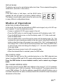
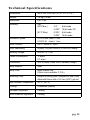
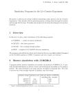
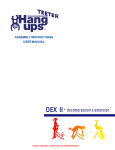
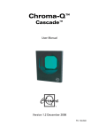
I-CUE
INTELLIGENT
MIRROR
Operations
Manual
Table of Contents
Product Overview
pg 1
Product Description
Operation
Drawings
I-Cue Mirror and Broadway scroller combined
I-Cue Mirror used without a color scroller
pg 2
pg 2
pg 3
pg 3
pg 4
pg 4
pg 6
pg 7
pg 9
pg 10
pg 12
pg 13
pg 15
pg 15
pg 15
I-Cue Intelligent Mirror Parts List
pg 16
Unpacking the unit
Control and power cables
Connections
Mounting the unit
Operating the unit
Modes of Operation
Summary of Control
Troubleshooting
Technical overview
Technical specifications
Product Overview
The I-Cue Mirror is designed to give years of trouble free use, providing that it is
regularly maintained and is used in accordance with the instructions detailed in this
manual. If you should experience any problems that fall outside of the scope of this
manual, please contact the selling dealer for further details.
If the selling dealer is unable to satisfy your servicing needs, please contact
the following, for full factory service:
ROTAD
1330 30th Street
Suite G
San Diego CA, 92154
Attn: Repair Department
800-468-0114 x25
pg 1
Product Description
The I-Cue Mirror is a motorized mirror attachment which mounts onto fixed position
spotlights to achieve many of the effects traditionally only available with high priced
intelligent moving lights The compact and stylish design is equally at home in a
theatre, exhibition centre, shopping mall, or car showroom.
The moving mirror accurately redirects a fixed position beam of light through a pan of
230˚ and a tilt of 57˚, making it a very cost-effective and space-saving option for
illuminating multiple locations using just a single spotlight. As well as being compatible
with most standard medium and narrow beam profile fixtures, the unit can also be
used with a color scroller to provide moving color and daisy chained to other lantern
accessories to combine moving light with dynamic color changing and gobo rotating
effects.
The I-Cue Mirror is designed to operate either on the USITT DMX512 (1990) protocol
or in stand-alone mode.
The DMX serial data system allows for the individual addressing of multiple units on
one data cabling system. The unit is addressed by using the three push button
switches and LED display. The unit equipped with a diagnostic section on the LED
display showing Power, DMX signal and level presence.
When operating in stand-alone mode, the I-Cue Mirror only requires a 24
VDC supply to operate.
Note: The quantity of I-Cue Mirrors used and the maximum cable length per power
supply output is dependent upon the size of PSU/splitter box used.
Operation
• Unpacking the Unit
• Control and power cables
• Connections
• Mounting the unit
• Operating the unit
• Modes of operation
• Troubleshooting
• Technical overview
• Technical specifications
pg 2
Unpacking the unit
The I-Cue Mirror package comes with the following items:
• I-Cue Mirror
• Safety wire (supplied fitted)
• User manual
The unit is shipped in a specially constructed shipping carton to provide protection to
the unit. Carefully open the carton and remove the unit by grasping the support arm
in the middle and lifting the unit vertically out of the carton. Next, carefully remove the
rubber restraint band used to stabilize the mirror unit during shipment.
Note: The packing material protects the fixture during shipment; always use it to
transport the fixture.
The front light shield had been designed so that it can act as a shipping support and
must be repositioned before using the unit. Loosen the two M4 wing screws on the
front of the unit and reposition the light shield by moving the shield downward to the
position necessary to prevent light leaks depending on the beam angle and focusing.
Control and power cables
The I-Cue Mirror utilizes an XLR 4-pin cable system.
In DMX mode, this is used to supply power and data transfer. Pins 1 and 4 are supply
24V DC power. Pins 2 and 3 supply USITT 1990 DMX512 control protocol, with a
ground/drain wire to the connector shell.
For use in ‘Stand-alone’mode, the unit requires a suitable 24V DC connected to Pins
1 and 4, with a ground/drain wire to the connector shell (not required, but suggested).
Damage will occur if power connections short to data or ground/shield connections.
When assembling XLR 4-pin cables, heat shrink should be used on each individual
pin to prevent short circuits. (See diagram on following page.)
Note: It is very important to ensure that the drain wire from the cable shield is
connected to both the XLR connector cases.
pg 3
Detail of connector wiring (typical)
The correct wiring between male and female connectors is ‘one to one’.
Pin #
Function
Minimum Cable size
1
2
3
4
Chassis
Ground (-ve)
Control data minus (-)
Control data plus (+)
24 VDC (+ve)
Cable shield/Drain wire
2.50mm_ (14 AWG)
0.35mm_ (22 AWG)
0.35mm_ (22 AWG)
2.50mm_ (14 AWG)
0.25mm_ (24 AWG)
(Note: Cable length should not exceed more than 75 M (250’) with return line)
Connections
Correct connection of the units to the power supply will decrease the chances of units
malfunctioning due to cabling problems. Please follow these basic rules:
a) Use the correct and gauge type of cable and connectors.
b) Keep cable runs as short as possible to reduce line loss.
c) Always use a return cable for each run.
This will ensure balanced DC power to all units that the line is correctly
terminated and that all units receive power if one link of the chain is faulty.
pg 4
Mounting the unit
For proper operation, the unit must be firmly attached to the light fixture it is mounted
on. To achieve this, the mounting plate of the unit has two flat springs at the outer
edge. The unit is designed to mount in the rear color frame slot of the ellipsoidal fixture.
The back plate should be inserted in the rear color slot and gently pushed down until
the unit is firmly seated in the bottom of the slot. The safety wire supplied with the
fixture should then be attached as a means of secondary fixing.
Input power and DMX should be brought to the unit by way of XLR-4 cable. If daisy
chaining is desired, a XLR-4 cable should be run from the output connector on the
unit to the next device in the chain.
When DMX is first applied to the unit, it will go through a homing sequence, which will
cause the mirror to momentarily move around.
Note: If the rear slot is not available for mounting of the unit because of the use of a
gel holder in this slot, the front slot may be used for mounting instead.
I-Cue Mirror mounted on a lighting fixture.
Ensure the safety wire is used as a means of secondary attachment.
pg 5
Operating the unit
All the unit functions are accessed using the LED display and the three push-button
switches on the left side panel.
3 digit Display
Red
Button
Control
RED button
BLACK button
BLUE button
3 digit display
Black
Button
Blue
Button
Function
Mode access and ‘Record’
Decrements the mode level, or value
Increments the mode level, or value
Displays modes, monitor, or blank display.
PUSH BUTTON OPERATION:
The RED button is used to scroll through the different modes of operation, and the
BLUE or BLACK buttons used to select the level, or value, in that mode. If any mode
or value is changed, the last digit of the display will flash until the RED button is
pushed to acknowledge (or record) the change.
DISPLAY OPERATION:
Power-up Display
On power-up, the display will show ‘ini’ during the initialization
sequence, and then show the DMX address.
MONITOR DISPLAY:
If left undisturbed for 5-7 seconds, the display will revert to ‘Monitor Mode’
• The first vertical bar indicates that
there is Power (24V DC) at the unit.
• The second vertical bar indicates that
there is Data (DMX) at the unit.
power
data
signal
level
• The horizontal bars indicate the data
Signal Level (DMX) at the unit.
(See also: ‘Troubleshooting’ section of this manual)
DISPLAY FLIP:
The display-viewing angle can be flipped through 180˚ by pressing and holding the
RED button, then pressing the BLACK button.
pg 6
DISPLAY BLANK:
The display can be set to auto-blackout after short time. This is selected through the
mode menu. (See later in this section)
RESET:
If the RED button is held down, and the BLUE button
pressed, the unit will reset to the factory default settings.
This feature is particularly useful when the units are use
in many different configurations/shows.
Modes of Operation
EFFECTIVE (STAND-ALONE) MODE
In this mode, the unit can be used without a DMX control signal; only a 24v DC supply is required. To use the stand-alone mode;
• Connect a suitable 24V DC power supply to the unit.
• Press the RED button to scroll through the menu until the display reads ‘At0’.
• Press the BLUE button once, so that the display reads ‘At1’ (Auto mode) and
press the RED button.
• Press the RED button to scroll through the menu until the display reads ‘Pn’. This
accesses the mirror panning movement in the auto mode. Using the BLUE/BLACK
buttons select the range of movement you require Pn0 – Pn7, continuous back &
forth sweep Pn8, or mirror held at the centre position Pn9. Press the RED button
to store the pan value and change the display to ‘tL’, the mirror tilting movement
in the auto mode.
• Repeat the above process to set a tilt movement value.
• When the desired effect is selected, press the RED button
DMX CONTROL MODE
In this mode, the unit can be fully controlled using two or four DMX channels (see
below). Acombined DMX and 24v DC supply cabling system is required in this system.
Press the RED button to move between modes, and to record any changes
made.
DMX CHANNELADDRESS MODE
This mode is used to set the DMX start address in the range of 1-511 (2 channels,
8-bit resolution) and 1-509 (4 channels, 16-bit resolution).The display shows the
current DMX address. (To alter the address, press BLUE or BLACK button once to
increment/ decrement the value; hold down the BLUE or BLACK for fast increments/
decrements of the value.
pg 7
PAN / TILT MOVEMENT MODES
These modes allow the user to reverse the direction of the pan, tilt, or pan and tilt
motion, when the configurations of the lighting fixture/mirror unit dictate. The display
shows either the pan movement or the tilt movement (‘Pn’ pan/ ‘tL’ tilt) and the current direction (‘0’= normal/ ‘1’ = reverse) of travel. (Press BLUE or BLACK button to
switch directions, and the RED button to change modes.)
DMX RESOLUTION
This mode is used to set the movement resolution, or accuracy, of the unit. The unit
operates either with two or four DMX control channels, or stand-alone mode (with no
DMX control). The display shows the current DMX mode (‘rn0’= 8-bit or ‘rn1’= 16-bit
resolution). (Press BLUE or BLACK to switch between modes.)
DISPLAY MODE
This mode is used to switch the display on or off. This feature can be used to blank
displays that may be an unwanted distraction. The display will re-activate when any
button is pressed. The display shows the current display mode (‘dP0’= display off or
‘dP1’= display on),(Press BLUE or BLACK to switch between on and off.)
DMX / AUTOMATIC MODE
This mode is used to select either DMX control or automatic (stand-alone) operation
of the unit. The display shows the current mode (‘At0’= DMX control, or ‘At1’=
automatic mode). (Press BLUE or BLACK to switch between modes.)
pg 8
Summary of control functions:
Note: - Press the RED button to move between modes, and to record any
changes made.
Mode
Description
Actions Required
Display
DMX channel
address mode
Sets the units DMX
address.
To alter the address,
press BLUE or BLACK
button once to increase
or decrease the value;
hold down the BLUE or
BLACK for fast incre ments/ decrements.
The display shows the current
DMX address.
In the range of 1-511
(2 channel, 8-bit resolution)
In the range of 1-509
(4 channel, 16-bit resolution).
Pan
movement
mode
This mode allows the
user to reverse the
direction of the pan
motion.
To alter the mode, press
BLUE or BLACK button
once to switch between
modes.
The display shows that the
PAN movement is set for
normal direction.
This mode allows the
user to reverse the
direction of the tilt
motion.
To alter the mode, press
BLUE or BLACK button
once to switch between
modes.
The display shows that the
TILT movement is set for
normal direction.
DMX
resolution
mode
Sets unit operating with
2or 4 DMX control
channels, with 8 or 16bit resolution.
To alter the mode, press
BLUE or BLACK button
once to switch between
modes.
The display shows the unit is
set for 8-bit resolution.
Display mode
This mode is used to
switch the display on or
off.
To alter the mode, press
BLUE or BLACK button
once to switch between
modes.
This shows that the display is
set for auto-blanking.
This mode allows the
user to select to
between DMX and
Automatic modes.
To alter the mode, press
BLUE or BLACK button
once to switch between
modes.
Tilt movement
mode
DMX/
Automatic
mode
The display shows that the
PAN movement is set for
reverse direction.
The display shows that the
TILT movement is set for
reverse direction.
The display shows the unit is
set for 16-bit resolution.
This shows that the display is
set to be permanently on.
The display shows that the unit
is set for DMX control.
The display shows that the unit
is set for automatic operation.
pg 9
DEFAULT SETTINGS:
‘Factory’default settings
If the unit is reset, using the RED button (held down), and
the BLUE button pressed for 2 Sec’s, the unit will revert
to the factory default settings.
The ‘Factory’ default settings put the unit in its normal operating mode.
DMX Address = 001
Pan/tilt direction = Normal
Resolution = 8-bit
Display = On
DMX/Auto = DMX
Display Flip = Normal
‘USER’ DEFAULT SETTINGS
Each time the RED record button is pressed, the unit will save that change and these
‘user defaults’ will take precedence on the next power cycle. These ‘User’ defaults
can be reset to the ‘factory’ defaults using the method detailed above.
Troubleshooting
The LED display aids in the troubleshooting of the system. These indicators are
located on the on the side panel of each unit.
power
data
signal
level
The first vertical bar indicates that there is power (24VDC) at the unit.
The second vertical bar indicates that there is data (DMX) at the unit.
The horizontal bars indicate the data (DMX) signal level at the unit.
Note: The signal level changes during normal operation of the unit, and is present
during stand-alone operation. 1st bar = 25%, 2nd bar = 50% and 3rd bar = 75%.
Note: A high percentage of problems are a direct result of poor cabling, corrupt
DMX control signals, and lack of suitable signal termination.
pg 10
SYMPTOM
POSSIBLE CAUSE
SOLUTION
Unit does not respond to
DMX control, but DMX
display indicator is on.
Unit set to wrong or different
DMX address.
Check DMX address
settings.
Unit does not respond to
DMX, DMX display indicator
is off.
Bad cable.
No DMX at splitter/PSU.
Check cable and DMX run
from the console.
Units run at different speeds.
Cable lengths are too long.
No cable return line.
Check the cable length and
configuration. Ensure there is a
cable return line in the system.
Units have dim display
indicators and run slowly.
Overloading of chain or
cable runs too long.
PSU overloaded.
Check voltage levels on last
unit. Should not be below
20VDC.
Display indicators appear OK
but unit does not move.
Mechanical (or electrical)
failure in the unit.
Turn unit on and off. Return
unit for repair.
The tilt doesn’t respond to
DMX.
16-bit mode setting when
8-bit control is intended, or
vice versa.
Check and reset.
Mirror panning/tilting in
opposite direction.
Pan/tilt reverse switch with
improper setting.
Check and reset.
The mirror vibrates in one
place when it is supposed to
move.
Broken motor cable
Popped out motor connector.
Contact distributor for service
Reconnect and check
pg 11
Technical overview
The electronics card consists of four key components: L298 Motor driver (x 2), 75176
Transceiver, and a processor. The 75176 transceiver operates in the receive configuration to convert serial protocol to a TTL level. All data relevant to the operation of
the unit is stored onboard in ‘flash’ memory. The majority of electronics problems are
usually created by external factors such as shorted cables, etc. The 75176 transceivers
are susceptible to damage if 24VDC is present on the DMX signal lines.
Troubleshooting is a process of elimination. First, rule out the other field factors (i.e.
faulty cables, power sources). If an electronics problem is suspected try replacing the
electronics card first. If accuracy problems should occur, check for obvious mechanical
problems. For technical advice and/ or parts, please contact your selling dealer or the
offices listed in this manual.
pg 12
Technical Specifications
Dimensions:
260 x 230 x 265 mm (10.25” x 9” x 10.5")
Weight:
1.6 Kg (3.5 lbs)
Resolution:
8 or 16 bit
Accuracy:
Pan
(230º Max.)
(57.3º Max.)
0.9º
0.028º
8-bit mode
16-bit mode Tilt
0.225º
0.028º
8-bit mode
16-bit mode
Movement Speed:
0-100% pan (max)= 2 sec
0-100% tilt (max)= 1 sec
DMX Protocol:
USITT DMX512 (1990)
DMX Addressing:
Digitally, via push buttons (3) and LED display
Working Voltage:
24 VDC (+/- 10%)
Power Consumption:
17 watts
0.7 amps
Connectors:
XLR-4 (male) in and XLR-4 (female) through
Body Material:
Steel
Body Color:
Black powder coat
(Other colors available, P.O.A.)
Mounting Plate:
Integral mounting plate, designed for use in any
ellipsoidal fixture with a 160 mm (6.25") gel slot.
Max. Ambient Temperature
40º C (104º F)
Cooling:
Convection (natural)
European Approvals:
Pending
North American Approvals:
Pending
pg 13
Specifications
pg 14
Drawings
I-Cue Mirror and Color Scroller combined.
I-Cue mirror used with a color scroller.
pg 15
I-Cue Intelligent Mirror Parts List
Part
IC-01 Mounting Plate Assembly
Number
205 81001 0000
IC-02 Broadway Mounting Bracket
205 81002 0000
IC-03 XLR Connector Assembly
205 81003 0000
IC-04 Stepper Motor Lead (each)
205 81004 0000
IC-05 Safety Chain Assembly
205 81005 0000
IC-06 Mirror/Mounting Bracket Assembly
205 81006 0000
IC-07 Digital Control Card
205 81007 0000
IC-08 Stepper Motor (each)
205 81008 0000
IC-09 Mirror Back Plate
205 81009 0000
IC-10 Front Light Shield Assembly
205 8101 00000
Please call Rosco or your local Rosco dealer for pricing and availability.
pg 16
Rosco Laboratories, Inc.
52 Harbor View Ave., Stamford, CT 06902
(203) 708-8900 1 (800) ROSCO NY FAX (203) 708-8919
1120 N. Citrus Ave., Hollywood, CA 90038
(323) 462-2233 1 (800) ROSCOLA FAX: (323) 462-3338
Rosco Laboratories, Ltd.
1241 Denison St. #44, Markham, Ontario, Canada L3R 4B4
(905) 475-1400 (888) ROSCO TO FAX: (905) 475-3351
Roscolab, Ltd.
Blanchard Works, Kangley Bridge Rd., Sydenham, London SE26 5AQ England
(208) 659-2300 FAX: (208) 659-3153
Rosco Iberica, S.A.
C/ Del Oro 76A, Pol. Industrial Sur, 28770 Colmenar Viejo, Madrid, Spain
(341) 846-3602 FAX: (341) 846-3634
Rosco do Brasil Ltda.
Rua Antonio De Barros, 827, São Paulo SP Brasil CEP 03401-000
Te l :( 0 11) 218-2865 FA X :( 0 11) 218-0193
Rosco Australia Pty Ltd.
42 Sawyer Lane, Artarmon 2064, New South Wales, Australia
(02) 9906-6262 FAX: (02) 9906-3430