1
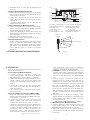
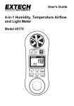
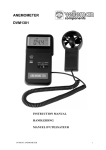
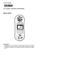
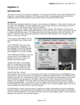
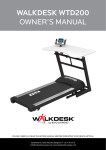
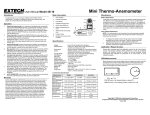
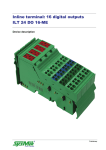
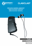
Fresh breeze
Strong breeze
Near gale
Gale
Strong gale
Storm
Violent storm
Hurricane
BEAUFORT SCALE AND PROBABLE WAVE HEIGHT
Wind Descriptions
Wave Height(m)
Wind Speed
Beaufort
Number
Wind
Wave
Knots
m/s
Probable
Maximum
Calm
–
–
–
<1 0-0.2
Light air
Ripples
1-3
0.3-1.5
0.1
0.1
Light breeze Small wavelets
4-6
1.6-3.3
0.2
0.3
Gentle breeze Large wavelets
7-10 3.4-5.4
0.6
1.0
Moderate breeze Small waves
11-16 5.5-7.9
1.0
1.5
2.0
2.5
Moderate waves
17-21 8.0-10.7
Large waves
22-27 10.8-13.8
3.0
4.0
Large waves
4.0
5.5
28-33 13.9-17.1
Moderately high waves 34-40 17.2-20.7
6.0
7.5
41-47 20.8-24.4
High waves
7.0
10.0
Very high waves
48-55 24.5-28.4
9.0
12.5
Exceptionally high waves 56-63 28.5-32.6
11.5
16.0
Exceptionally high waves 64-71 32.7-36.9
14.0
>16
0
1
2
3
4
5
6
7
8
9
10
11
12
MULTI FUNCTIONAL
ANEMOMETER
This Anemometer is small in size, light in
weight, easy to carry. Although complex
and advanced, it is convenient to use and
operate. Its ruggedness will allow many
years of use if proper operating
techniques are followed. Please read the
following instructions carefully and
always keep this manual within easy
reach.
11
DEL/MENU key. (Note: 'ArEA ' is initially
displayed but ignore this . And keep holding
the button till 'AUΓO ' is displayed.)
6.2 The previously set value will be displayed
on the LCD. Please use UP or DOWN key to
change the value to the correct time from 1 to
9 minutes as desired. To disable the function
of auto power off, just preset the time to 0.
That is, the meter can only be shut down
manually in such a case.
6.3 To quit the setting, just press any key except
the UP or DOWN key. This procedure can be
carried out whenever required as each time to
change the time of auto power off.
7.BATTERY REPLACEMENT
7.1 When battery voltage less than approx. 5v, it
is necessary to replace the batteries.
7.2 Install a the batteries 4x1.5v AAA (UM-4)
correctly into the case.
7.3 If the instrument is not to be used for any
extended period, remove batteries.
8. USEFUL EQUATIONS AND
CONVERSIONS
Area equation for rectangular or square ducts
Area =W x H
Operating
Max. 80% RH
Humidity
Power Supply 4x1.5AAA size
260g (0.57lb) including batteries
Weight
& probe
Main instrument: 156x67x28mm
Dimensions
( 6.1x2.6x1.1" )
Sensor Head: 72mm Diameter
Operational manual.. ......... ..1pcs
Standard
Carrying case .........................1pcs
Delivery
Sensor probe ..........................1pcs
Optional
Cable+Software for RS232C
Accessories
2.2 Range Specifications
Air Velocity
m/s (meters
per sec)
km/h (kilometers/hour)
ft/min (feet
per minute)
knots (nautical
MPH)
0.4-45.0
0.1 m/s
1.4-162.0
0.1 km/hr
80-8860
0.1 ft/min
0.8-88.0
0.1 knots
0-9999
0.001 to1
0-9999
0.001 to1
w
9
± (2%+
0.1m/s)
±(2% +
0.1km/hr)
±(2% +
1ft/min)
±(2% +
0.1 nots)
Air Flow
CMM (cubic
meters/min)
CFM (cubic
ft/min)
H
Resolution Accuracy
Range
2
±(2% +1
m³/min )
±(2% +1
ft³/min )
1.APPLICATION
Widely used in data collection for boiler,
r e f r i g e r a t i o n i n d u s t r y, v e n t i l a t i o n d u c t ,
environment monitor, navigation measurement,
weather forecast, collection of the weather
datum for outdoor busywork and fire department.
2. SPECIFICATIONS
R
Cubic equations
CFM (ft 3/min) = Air Velocity (ft/min) x Area (ft 2)
CMM (m 3/min) = Air Velocity (m/sec) x Area (m 2) x 60
2.1 General Specifications
Display
Area equation for circular ducts
Circular Duct
A=π R 2
( A= 3.14 x R x R)
0.5" (13 mm) 4-digit LCD
Air Velocity: m/s, km/h, ft/min,
knots
9.UNITS CONVERSION TABLE
m/s
ft/min
knot
km/hr mph
Air Flow: CMM (m³/ min) ;
Measurement
CFM (ft³/ min)
units
Beaufort Scale: Force
Wave Height: m
Temp: °C & °F
Maximum Value
Data hold
Data memorized 24 groups
Sampling rate reading per second approx.
Air velocity/flow sensor:
Sensors
Conventional angled vane arms
with low-friction ball bearing.
Temperature sensor:
Precision thermistor
Automatic
0-9 minutes set by users
Power off
Data Output
RS 232 C serial interface
Operating
32°F to 122°F (0°C to 50°C)
Temperature
10. BEAUFORT SCALE AND PROBABLE
WAVE HEIGHT
1
10
Resolution Accuracy
Range
Beaufort
Scale
Wave Height
Air
Temperature
0-12
0.1
±0.5
0-14
0.1
±0.1
32 - 140℉
0.1 ℉
0-60 ℃
0.1 ℃
0.9 ℉
0.5 ℃
3. METER DESCRIPTIONS
3-11
3-1
3-12
3-2
3-3
3-4
3-5
3-1 Display
3-2 Function key
3-3 Unit selection
3-4 Back light
3-5 Power button
3-6 Down/Read button
3-7 Up/Save button
3-6
3-7
3-8
3-9
3-10
1knot
0.5144
1km/hr 0.2778
1mph 0.4464
101.27
1
54.69
0.54
1.8519 1.1523
1
0.6222
87.89
0.8679
1.6071
1
5.1 When in ' M ' state, you can save the reading
together with measuring conditions to the
memory of the meter by pressing the
UP/SAVE key. Then the icon ' M ' changes to
'M' automatically
while the number of
memorized readings increases 1.
5.2 No matter in ' M ' state or 'M' state, the
memorized data can be browsed by depressing
the READ key. The browsing state is marked
in 'R' on display. When in 'R' state, all the
readings memorized can be recalled by
depressing the UP key or DOWN key.
5.3 To delete the memorized value in memory, just
enter the browsing state and locate the reading to
be deleted by the UP key or DOWN key, then
depress the DEL key and release it immediately.If
there is an "Err0" on the display, it indicates there
is no reading to delete any more.
6. HOW TO SET THE TIME OF AUTO
POWER OFF
Fig. 1
3-8 Delete/Menu button
3-9 Max. Value hold
3-10 External power
socket
3-11 RS232C socket
3-12 Vane probe
3
1
1m/s
196.87 1.944
3.6
2.24
1
1ft/min 0.00508
0.00987 0.01829 0.01138
The default setting for auto power off at the
factory is 5 minutes. That means the meter will
auto power off 5 minutes from the time of last
key operation. Users can change it to any value
between 1-9 minutes by following steps.
6.1 Just press and hold the DEL/MENU key long
enough till 'AUΓO ' showing on the
display then release it immediately . It
takes about 10 seconds from depressing the
8
c . Beaufort force or scale will be displayed on
the LCD.
4.4 Wave Height Measurements
a. Select Wave function using the FUNCTION
button. The LCD will display Wave when the
wave mode is selected.
b. Place the sensor in the air current with the
yellow dot side of the vane facing the air flow
(see Fig.3)
c. Probable Wave Height in the sea will be
displayed on the LCD.
4.5 Air temperature Measurements
a. Select Temp function using the FUNCTION
button. The LCD will display Temp. when the
temperature mode is selected.
b. Select the desired air Temp units using the
UNIT button. The LCD will reflect the current
unit selection (°F or °C ).
c. Place the sensor in the air current.
d. Temperature will be displayed on the LCD.
4.6 Data Hold Feature
While taking measurements, press the MAX
button to hold the Maximum reading. The
max indicator will appear on the LCD when
the display is in Maximum Data Hold mode.
Press HOLD again to return to normal
operation.
5.STORING AND RECALLING READINGS
7
4.OPERATION
Turn on the meter using the Power button before
taking measurements.
4.1 Air Velocity Measurements
a. Select velocity function using the
FUNCTION button. The LCD will display
Speed when the velocity mode is selected.
b. Select the desired air velocity units using the
UNIT button. The LCD will reflect the
current unit selection (ft/min, km/h, m/s or
knots).
c. Place the sensor in the air current with
the yellow dot side of the vane facing the air
flow (see Fig.3)
d. Air velocity will be displayed on the upper
line of the LCD.
4.2 Air Flow Measurements (CMM / CFM)
a. Select flow function using the FUNCTION
button. The LCD will display Flow when the
flow mode is selected.
b. Select the desired air flow units using the
UNIT button. The LCD will reflect the
current unit selection (m³/ min, ft³/min) .
c. Airflow is based on the specific dimensions
of the duct being measured. For the meter to
correctly measure CMM ( Cubic Meter per
minute m³/min) or CFM ( Cubic Feet per
minute ft³ / min), the user must input the
area of the duct. Failing to input the correct
5
3-13
3-18
3-14
3-19
3-15
3-20
3-21
3-22
3-23
3-16
3-17
Fig. 2
3-13 Max. value indicator
3-14 Parameter indicator
3-15 Temp. unit
3-16 B. Scale unit
3-17 Area unit
3-18 Speed & Flow unit
3-19 measurement reading
3-20 Browsing indicator
3-21 Number of reading
memorized
3-22 Low battery indicator
3-23 Memory indicator
Side view
of Vane
20°
Air direction
20°
Yellow Mark
Fig. 3
4
area dimensions will result in erroneous
readings. To input the area dimension,
c.1 just press and hold the DEL/MENU key long
enough until ' ArEA ' showing on the display,
then release it immediately . It takes about 8
seconds from depressing the DEL/MENU
key.
c.2 The previously stored area value will be
displayed on the LCD. Please use UP or
DOWN key to change the area value to the
correct area dimensions . The longer you press
the UP or DOWN key , the larger the
increment of the value changes . To quit , just
press any key except the UP or DOWN key .
This procedure can be carried out whenever
required as each time the area of the duct is
changed .
d. Place the vane in the air flow (Fig.3). Wait
approximately 2 seconds for a stabilized Air
Flow reading. The equation below is used to
calculate Air Flow:
AIR FLOW = (AIR VELOCITY) x (AREA)
4.3 Beaufort Scale Measurements
a. Select Beaufort scale function using the
FUNCTION button. The LCD will display
B.Scale when the flow mode is selected .
b. Place the sensor in the air current with the
yellow dot side of the vane facing the air flow
(see Fig.3)
6