1
INFRA-RED
FLAME
DETECTION
FlameVision
FV300 SERIES
IR ARRAY
FLAME
DETECTORS
USER MANUAL
FV300 USER MANUAL
INDEX
PAGE
INTRODUCION
1
PRINCIPLES OF OPERATION
3
APPLICATION
7
SYSTEM DESIGN INFORMATION
10
OPERATION
29
INSTALLATION
34
COMMISSIONING
43
MAINTENANCE
51
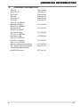
ORDERING INFORMATION
53
ANNEX A - MODBUS OVERVIEW
54
ANNEX B - CCTV DETAILS
58
DETECTOR INFORMATION
65
INTRODUCTION
1.
INTRODUCTION
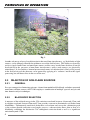
The FV300 FlameVision range is a new family of advanced, high technology infra-red array flame
detectors with reliable wide area flame detection and excellent false alarm immunity. The FV300
FlameVision detectors offer a major improvement in both flame detection capability and immunity
to false alarm sources over triple IR detectors. The detector can be supplied with an optional builtin colour video camera for connection to CCTV systems to display the field of view with an
overlay showing alarm location and status information. All FV300 models provide fire and fault
relays, 4-20mA output and a field network interface as standard for connecting to external
equipment.
The FV300 FlameVision detectors use an array of 256 sensitive infra-red sensors to view the
protected area. The IR array is combined with 2 other optical sensors to provide 3 highly sensitive
optical channels. Powerful algorithms running on a Digital Signal Processor (DSP) are tuned to the
characteristics of a fire and analyse the signals from these 3 channels to reliably identify fires. The
FV300 offers sensitive flame detection over a long range with a wide and consistent field of view.
It also has excellent immunity to false alarms.
One of the key advantages of using an array is that the detector can identify the location of the
flame within the field of view. The location information is used to overlay a marker on the live
camera image to highlight the fire. The user can quickly see the location of the fire and decide on
the appropriate action. The location information is also available on the field network interface.
The FV300 FlameVision range is highly configurable to provide flexible detectors for all
applications. The most common options are set using DIP switches with more advanced options
set using a PC tool. The detectors also include features designed to reduce maintenance, including
remote configuration, internal diagnostic logs and built-in alarm and window cleanliness tests. A
portable test tool, suitable for use in hazardous areas is available to operate the alarm and window
test facilities remotely.
The FV300 FlameVison detectors are housed in a rugged stainless steel enclosure suitable for harsh
environments. All detectors share the same detection circuitry, optics and mechanics and the
choice of two back box variants gives two basic flameproof (explosion proof) flame detector
models. The FV311S series features cable gland entries and integral cable termination
facility. The FV312S series features a sealed back box with cable for connection of field wiring
via an EExe junction box.
Each model is available in three variants depending whether the detector is fitted with an internal
CCTV camera and which type of camera is fitted. The range of variants includes:
FV311S
FV311SC
FV311SC-N
FV312S
FV312SC
FV312SC-N
Cable entries
Cable entries
Cable entries
Sealed back box
Sealed back box
Sealed back box
No CCTV camera
PAL CCTV camera
NTSC CCTV camera
No CCTV camera
PAL CCTV camera
NTSC CCTV camera
1
O
N
PE
EN
WH
AN
OSIVE GAS AT
MO
EXPL
SP
HE
RE
tyco
FlameVision
FV311SC-N
IS
PR
EN
ES
T
S/No.XXXXX
DO
NO
T
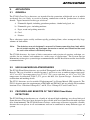
INTRODUCTION
PATENTED
ATEX
Baseefa07
ATEX0178X
FM
II 2 G D
APPROVED
IECEx
Ui = 30V
Pi = 10W
BAS07.00488X
Ex d IIC
Ex t D A21
o
T135 C
o
o
Ta: - 40 C to + 80 C
o
T100 C
o
o
Ta: - 40 C to + 70 C
o
o
Ta : - 40 C to + 80 C
CI I Div 1 Grp B,C,D
CI II Grp E,F,G CI III
SEAL
CONDUITS
WITHIN 18"
1180
IP66/67
243532
2079801
Ex d IIC T4/T5
DIP A21 IP66/67
T135°C/T100°C
Nm
TO
K
25 (10
R Q CA
TYCO TW16 5DB UK
a + FT
T
UE BLE
:
.
E
CO
TING LB
VER NTRIES: M20 CABLE RA ) TO 7
BOLT
-70
S (MIN. GRADE A4
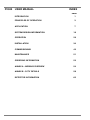
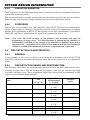
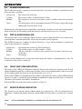
Fig. 1
)
FV300 Series Detector - General View
Summary of features:
Advanced array based detector
Powerful signal processing on DSP with algorithms to give reliable flame detection
Detection range:
Over 50m for 0.1m2 n-heptane pan fire
Field of view:
90° horizontal, 80° vertical with full range maintained
High immunity to false alarms
Solar blind
Built-in video camera (option):
View protected area with alarm location and status
overlay
Masking of areas in field of view
Self-test: Automatic Self-test of detector features
: Window test (automatic/manual/remote operation)
: Alarm test (automatic/manual/remote operation)
Electrical Interfaces (Standard on all models):
2
Fire and Fault relays (NO or NC contacts)
4 - 20 mA (Source or Sink)
Video twisted pair balanced line (NSTC/PAL)
Modbus (RS485) interface
Configuration port (RS485)
PRINCIPLES OF OPERATION
2.
PRINCIPLES OF OPERATION
2.1
GENERAL
In order to optimise the detection of flames from hydrocarbon, the FV300 detectors analyse radiant
infrared energy at the peak carbon dioxide emission wavelength around 4.5µm. In a separate guard
channel, the detectors also sense additional wavelengths between 4.8 and 5.8µm to determine
whether the spectral content received possesses the signature of a real flame. The signal received
is further analysed to determine whether its modulation frequency has the irregular and quasirandom characteristic of a flame within a pre-determined frequency band. A powerful Digital
Signal Processor (DSP) is continuously analysing the radiation signals to detect a fire.
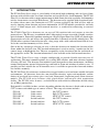
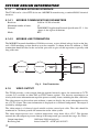
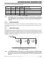
2.2
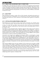
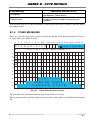
ARRAY-BASED FLAME DETECTION
The field of view of the detector is scanned by a 16 by 16 array of highly sensitive pyroelectric
sensors. A sapphire convergent lens collimates the infrared energy onto the surface of the array. A
precise narrow band interference filter centred at 4.5µm then eliminates unwanted wavelengths.
If the signal received is of sufficient intensity to form a detectable image on several elements on
the array, called a cluster, the DSP analyses their frequency characteristic as well as their
correlation and spectral ratio with the signal present on the guard channel. A value representing
the instant probability that a real fire is present, results from this calculation. This probability
value is then analysed over a period of time to confirm whether a flame has been detected.
SINGLE ACTIVE
ARRAY CLUSTER
Fig. 2
MULTIPLE ACTIVE
ARRAY CLUSTERS
Array Cluster
By using an array as the sensing component, the FV300 detectors are able to locate the angular
position of the fire within the field of view. The detectors use this information to provide
superimposed location information on a composite video output from an internal CCTV camera
and to signal the coordinates of this location on its field bus data output. The array, together with
its optical components and software intelligent interpolation gives the detector an angular
resolution of better than 0.5 degrees.
Array-based detection also enables the FV300 detectors to identify several separate radiation
sources within its field of view. For practical purposes, the number of separate detectable sources
that are reported has been limited to the four strongest, with information on these available on both
video and field bus outputs.
3
PRINCIPLES OF OPERATION
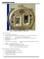
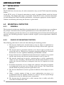
Fig. 3
Another advantage of array-based detection is that non-flame interferences, eg, black body or light
sources, can be uniquely identified to within an area of the field of view. This ability to separately
analyse signals from flame and non-flame sources enables array based flame detectors to not be
desensitised in the presence of non-flame interferences, unless such sources are physically
coincidental. It also enables a known but unwanted source of radiation that is likely to be present
in the field of view of the detectors, to be ignored by applying of a ‘software’ mask to the signal
processing but still detect fires in the rest of the area.
2.3
2.3.1
REJECTION OF NON-FLAME SOURCES
GENERAL
In a new concept for eliminating nuisance alarms from modulated blackbody and other unwanted
non-flame radiation sources, the FV300 employs a combination of multiple spectral analysis and
time domain analysis techniques.
2.3.2
BLACKBODY REJECTION
A measure of the radiated energy in the CO2 emission waveband, between 4.4µm and 4.7µm, and
in a higher waveband, between 5µm and 5.7µm, provides a means to discriminate real flames from
blackbodies. Unfortunately, most fuels do not have a clean burn and, except for a distinctive peak
at the carbon dioxide emission wavelength, possess a characteristic more akin to that of a
blackbody, exhibiting the distinctive CO2 atmospheric emission band as well as a significant
emission beyond 4.7µm.
4
PRINCIPLES OF OPERATION
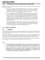
To ensure that flames from all potential fuels are detected whilst minimising the risk of nuisance
alarms, an optimum spectral signature of a flame, defined by its ratio at the two measuring
wavebands (A/B in Fig. 4) has been established experimentally by lighting characteristic fuels at
different distances. This was compared with a similarly obtained blackbody ratio (C/D in Fig. 5),
enabling an optimum flame decision threshold to be defined.
Energy
Petrol fire
at 20m
A
B
3
3.5
4
4.5
5
5.5
6
Wavelength (m)
Fig. 4
Measured Flame Spectral Characteristics
Energy
Black body
1200 K at 2m
C
3
3.5
4
4.5
D
5
5.5
6
Wavelength (m)
Fig. 5 Measured Blackbody Spectral Characteristics
In addition to the above spectral analysis, the modulated infrared energy seen by each activated
cluster of the array is further analysed for frequency irregularities over a period of time that would
be typical of that of a flame, but not a blackbody source. With this sophisticated level of signal
processing, the FV300 FlameVision range of detectors offers a high degree of immunity to all
blackbody sources likely to be present in the application.
5
PRINCIPLES OF OPERATION
2.3.3
IMMUNITY TO SOLAR RADIATION
Modulated radiation from direct or reflected sunlight as well as modulated radiation from strong
sources of artificial lighting can produce an unwanted response from infrared flame detectors. To
counter this possibility, the FV300 detector looks for the flame in a very narrow waveband where
most of the sun radiation is absorbed by CO2 gases in the atmosphere. Secondary re-radiation
effects from sun heated optical components is minimised by an additional long wave IR filter on
the guard channel and a special sun-block coating on the array lens.
To further eliminate the risk of unwanted alarms from modulated sun radiation or radiation from
sources of artificial lighting, the FV300 incorporates a third sensor looking specifically for
radiation in the visible and short wave infrared band. The output signal from this sensor is mixed
with that of the long wavelength infrared filter to operate as a spectral guard for modulated sunlight
or any other strong artificial lights.
2.4
DETECTION RANGE
The FV300 FlameVision detectors can detect a fully developed 0.1 m2 n-heptane or petrol
(gasoline) fire at 50m. The collimating optics and the ability of the detector to separately process
signals from individual sensing elements of the array enables the detector to correct signal losses
due to off-axis incident angles. This results in a ‘flatter’ response throughout the detector field of
view. Performance details are given in the System Design Information section.
2.5
MULTIPLE FIRES DETECTION
The FV300 sensor array, together with its associated digital signal processing, can identify more
than one fire event occurring at the same time within the detector field of view. At any one time,
up to four alarms from the strongest flames can be reported and signalled. Fires that are
sufficiently close or in the same line of sight will generate merged activity clusters on the sensor
array and can only be identified as a single fire event.
2.6
DETECTION OF FLAME IN THE PRESENCE OF BLACKBODY
The ability of the detector to identify and process multiple activity clusters within its field of view
allows radiation signals from fire sources and blackbody sources to be analysed separately for both
their spectral and time domain signature. Thus, in the presence of modulated blackbody sources,
the detector will not generally be desensitised when responding to a fire event. In some
applications, large blackbody sources may overshadow areas of the field of view where detection
is required. In these cases, care should be taken in the number and positioning of detectors that are
needed for achieving the degree of protection required.
6
APPLICATION
3.
APPLICATION
3.1
GENERAL
The FV300 FlameVision detectors are intended for the protection of high-risk areas in which
accidental fires are likely to result in flaming combustion with the production of carbon
dioxide. Typical materials in this type of risk are:
a) Flammable liquids, including petroleum products, alcohol and glycol, etc.
b) Flammable gases, including methane.
c) Paper, wood and packing materials.
d) Coal.
e) Plastics.
These substances ignite readily and burn rapidly, producing flame, often accompanied by large
volumes of dark smoke.
Note:
The detectors are not designed to respond to flames emanating from fuels which
do not contain carbon, eg, hydrogen, ammonia or metals, and should not be used
for such risks without satisfactory testing.
The FV300 detectors, by virtue of their construction and rejection of spurious radiation, are
suitable for use indoors and outdoors in a wide range of applications. The System Design
Information section gives system design recommendations and the Installation section, installation
recommendations.
3.2
USE IN HAZARDOUS ATMOSPHERES
The FV300 FlameVision detectors are certified 'Flameproof' to the ATEX directive and IECEx by
Baseefa. They are classified as suitable for zone 1 and 2 areas over an ambient temperature range
-40°C to +80°C for temperature class T135°C (T4) gasses and dust, or -40°C to +70°C for
temperature classification T100°C (T5) gasses and dust. See System Design - Section 4.9 for
certification and marking details.
The FV311 detectors are also certified ‘Explosionproof’ by Factory Mutual (FM) approvals. The
FV311 detectors meet the requirements of FM 3600 and FM 3615 and are suitable for hazardous
locations Class 1 Division1 Groups B, C and D, Class 2 Groups E, F and G and Class 3.
3.3
FEATURES AND BENEFITS OF THE FV300 FlameVision
DETECTORS
The FV300 Flamevision detectors are a family of advanced, high technology array based infra-red
flame detectors. They have been designed to give reliable wide area flame detection with excellent
false alarm immunity. The FV300 detectors also have a wide range of features to provide a flexible
detector that can operate in all environments and can be connected to many different types of
system.
7
APPLICATION
Summary of FV300 FlameVision features and benefits:
Detection:
The FV300 provides high sensitivity flame detection with high false alarm immunity,
undiminished throughout a wide field of view.
An infra-red array combined with 2 other optical sensors provides 3 sensitive optical
channels. Signals are analysed by powerful algorithms running on a DSP to give reliable
flame detection. The algorithms have been extensively proven with real fires.
Operational range 50m (0.1m2 heptane pan fire) with no reduction in range across the
90° horizontal and 80° vertical field of view.
Consistent detection of different sizes of flames from a wide range of hydrocarbon fuels
from alcohol to aviation fuel (JP4 and JP5).
Excellent false alarm immunity. Proven to be immune to common radiation sources
(continuous or modulated) such as halogen lamps, welding, heaters, etc.
Solar blind.
By using an array, the FV300 can locate the flame within the field of view and displays the
information on the video overlay to pinpoint the location of the fire enabling more effective
counter measures to be taken. The location information is also available on the network
interface for use in external systems.
Software Field of View Masking: The array can locate and track active known permanent
sources, such as a flare stack, within the field of view. The detector can be configured to
ignore such sources, including flames, in a certain area of the field of view. External,
physical blinkers and shutters are not required.
Interfaces:
Fire and fault relays, 4-20mA output and a field network (RS485) interface are standard
on all models to connect to monitoring equipment.
Modbus protocol is supported on the field network interface to connect to PLCs.
Internal wide angle CCTV camera (optional) covering detection field of view. With a video
output (balanced line) to connect to on-site video monitoring (CCTV) system. Detector
overlays identification information on the video image to show alarm location and details.
Functions:
Window heater standard on all models to reduce misting.
Flexible configuration: Primary options on DIP switches such as alarm delay timings, fire/
fault latching, etc. Advanced options set using PC configuration tool such as mask area,
network parameters etc.
Regular self-testing of critical electronic circuits and regular monitoring of the detector
window cleanliness and optical path monitoring (OPM) which reduces the frequency of
regular maintenance visits.
Integral flame simulation for verification of detection path enabling either easy walktesting of the installation or testing by remote control to ensure continued reliability of the
detector operation.
Diagnostic logs: The detector keeps a log of all events, alarms etc. This information can be
read remotely using the configuration tool for maintenance purposes.
Hand-held walk test tool available to initiate alarm and window tests and reset detector on
demand. Tool can activate detectors from up to 6m away so can be used without poles or
other access methods. Walk-test tool is ATEX approved by Baseefa and can be used in
hazardous areas.
8
APPLICATION
Mechanical:
Rugged two part stainless steel 316L housing sealed to IP66/IP67 for use in harsh
environments.
Choice of gland entry back box with terminal blocks for direct field wire termination or
sealed entry back box fitted with a flying lead to connect to an external EExe junction box.
Optional mounting bracket in 316L stainless steel allows 90° adjustment in both horizontal
and vertical plane and includes angular markings.
Detector ATEX and IECEx certified (‘Flameproof’) by Baseefa.
The FV300 FlameVision series are infrared flame detectors giving the FV300 major benefits over
detectors working in the visible or ultra-violet regions of the spectrum, such as UV detectors or
video flame detectors. These include:
Highly sensitive to flame, thus increasing probability of early detection of hydrocarbon
fires over a longer range.
Much less affected by window contamination from dirt and oil deposit, thus decreasing
maintenance requirements leading to operating cost reduction.
Able to see flames through smoke and through high densities of solvent vapours thus
increasing the probability of early detection of hydrocarbon fires, particularly from heavy
black smoke generating fuels.
3.4
POINTS TO NOTE WHEN USING FV300 FlameVision DETECTORS
OR S200 FLAME DETECTORS
The FV300 FlameVision series are a whole new range of flame detectors developed from the
knowledge and experience built up from previous detectors such as the S100 and S200 series.
However, the FV300 series is not a complete replacement for the existing detectors and the
following should be considered:
The FV300 will only be available in Flameproof versions. An IS version will not be
available due to the power consumed, especially by the camera. The S200 range should
continue to be used in these applications.
The FV300 consumes more power than the S200 and needs an external PSU.
The FV300 is smaller than the S200 and does not fit the S100/200 bracket. To replace an
S200 with an FV300 the FV300 bracket will have to be fitted.
FV300 has a discrete 4-20mA level for pre-alarm. It is not variable like the S200.
The FV300 has a consistent range over the field of view and automatically adjusts to the
distance and size of a fire. It does not need adjustable sensitivity as used on the S200.
The FV300 has a clear field of view, there are no blind spots.
The FV300 provides all electrical interfaces (relays, 4-20mA, etc.) on ALL models.
9
SYSTEM DESIGN INFORMATION
4.
SYSTEM DESIGN INFORMATION
* IT IS RECOMMENDED TO PROVIDE CABLES FOR
THIS PORT TO ENABLE REMOTE CONFIGURATION
AND DIAGNOSTICS
TO PC
REMOTE INDICATOR
(OPTION)
ACTIVATE:
ALARM TEST
RESET
WINDOW TEST
}
10
CONFIGURATION/DIAGNOSTICS PORT*
VIDEO (BALANCED PAIR)
NETWORK INTERFACE
4 - 20 mA OUTPUT
WALK TEST INPUT
IR
WALK TEST TOOL
POWER (18 - 30V dc)
FIRE RELAY
FAULT RELAY
}
TO CCTV SYSTEM
TO
MONITORING
SYSTEM
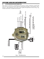
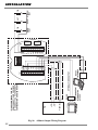
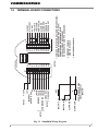
The electrical, mechanical, environmental characteristics and the performance of the FV300
FlameVision series detectors must be taken into account when designing a system which uses these
detectors. This information is given in this section, together with guidance on detector siting. Fig.
6 shows the interfaces available on the detectors.
Fig. 6
FV300 Interfaces
SYSTEM DESIGN INFORMATION
4.1 ELECTRICAL CHARACTERISTICS
4.1.1
GENERAL
Supply voltage:
20V to 30V dc
Power:
up to 10W (depending on model)
Quiescent current:
- no camera fitted:
158mA at 24V
- with camera:
196mA at 24V
Alarm current:
- no camera fitted:
166mA at 24V
- with camera:
205mA at 24V
Additional current when using 4 to 20 mA output in source mode
- Quiescent:
4.0mA at 24V
- Alarm:
11.5mA at 24V
Window heater additional current:
VSupply ÷ 270Ω (90mΑ at 24V)
Stabilisation time after power up:
5 - 20 minutes
Note:
4.1.2
For CSA compliance the detectors must be powered from a class 2 certified PSU.
RELAY CONTACT OUTPUTS
Fault relay:
Alarm relay:
Alarm relay coil monitoring:
Contact rating:
4.1.3
Selectable normally closed or open contact.
Selectable normally closed or open contact.
Supplied as standard.
2A at 30V dc
4 to 20 mA OUTPUT
Signalling currents:
General fault:
Window dirty:
Normal:
Pre-alarm:
Alarm:
Maximum current monitor resistance
in source mode:
Nominal
0mA
2mA
4.5mA
11.5mA
17mA
Range
(0.0 to 0.7mA)
(1 to 3mA)
(3.5 to 5.5mA)
(10 to 13mA)
(15 to 19mA)
130Ω
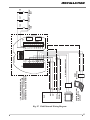
Output mode: Selectable current sink or current source output (SW2).
4-20mA SINK MODE
4-20mA SOURCE MODE
24V
R MONITOR
100R
4-20mA OUTPUT
7.7V
100R
4-20mA OUTPUT
DETECTOR
R MONITOR
7.7V
DETECTOR
R MONITOR 100R-120R
0V
R MONITOR 100R-390R
Fig. 7
4-20mA Current Sink/Source Wiring Diagrams
11
SYSTEM DESIGN INFORMATION
4.1.4
MODBUS NETWORK INTERFACE
The FV300 can be a slave RTU device on a MODBUS network using a standard RS485 electrical
interface.
4.1.4.1
MODBUS COMMUNICATIONS PARAMETERS
Baud rate:
Maximum number of units:
Protocol:
Mode:
4.1.4.2
9,600 or 19,200 selectable.
32
To MODBUS Application Protocol Specification V1.1 - See
‘Annex A for register definitions
RTU
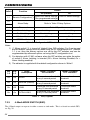
MODBUS LINE TERMINATION
The MODBUS network should have 390Ω bias resistors, to give defined voltage levels on the line,
and a 220Ω matching resistor fitted near to the controller, as shown below. In addition, a 220Ω
termination should be fitted at the end of the pair cable to give reliable operation, especially with
long cable runs.
+5V
390Ω
220Ω
DETECTOR
DETECTOR
TWISTED
PAIR
220Ω
MODBUS
CONTROLLER
390Ω
0V
Fig. 8
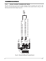
4.1.5
Line Termination
VIDEO OUTPUT
The FV300 provides a video output from the optional internal camera for connection to CCTV
systems. It is available in either PAL or NTSC format (option). The detector superimposes an
overlay with status information on top of the picture to notify alarms, including location, and faults.
The video output can be used on units without a camera to display the status information overlay
on a CCTV system. The status information is displayed on a coloured background. The output is
enabled by configuration.
The video output is a balanced signal suitable to drive twisted pair cable. The cable should be
terminated in a balun to provide the connection to the video system.
The video output operates over a reduced temperature range from -40 to +70°C. The detector
controls the video output to prevent damage if the temperature goes outside the range. See Table 1.
Output impedance:
Receiving end:
12
100Ω into 100Ω twisted pair.
Active balun NV - 652W (603.015.027).
SYSTEM DESIGN INFORMATION
A 24V supply is required - it must be isolated from detector supply if the RS485 interface option
is used. Leave the balun ground connection O/C.
From (º C)
To(º C)
+70
+50
-10
+80
+70
+50
-30
-40
-10
-30
Note:
4.1.6
Text
overlay
Off
On
On
Video
camera
Off
Off
On
Video output
No video signal
Overlay with blue background
Camera or blue background with
overlay
On
Off
Overlay with blue background
Off
Off
No video signal
Table. 1 Video Output
The detector monitors the internal temperature to decide when to switch the
video output mode. The temperatures in Table 1 are external temperatures and
vary depending on the environmental conditions and if the window heater is
enabled.
WINDOW HEATER
The FV300 has a heater to warm the sensing window and prevent misting. The heater is enabled
on the DIP switches. When enabled, the heater will turn off when the detector temperature rises
above +40º C.
4.1.7
WALK TEST INPUT
The walk test input provides a means to connect remote switches to the FV300 detector to activate
the alarm test and window test (OPM) functions or to reset the detector. The required operation is
selected by connecting the appropriate resistor value, see Fig 9, between the walk test input and
0V using a momentary switch. The switch should be opened once the function has been
activated. See Figs. 24, 25 and 26.
WALK TEST
INPUT
15k
WINDOW
TEST
4k7
RESET
1k8
ALARM
TEST
0V
Fig. 9 Walk Test Input
Note:
The FV300 detectors are approved for use in both gas and dust atmospheres but
the WT300 Test tool is only approved for gas atmospheres. Where FV300
detectors are installed in dust risk environments the walk-test wired input should
be used.
13
SYSTEM DESIGN INFORMATION
4.1.8
REMOTE LED
An external LED indicator can be connected to the detector. The output follows the indications of
the alarm LED. The connection is as follows:
+12V
REMOTE ALARM
LED OUTPUT
140R
R*
DETECTOR
0V
* OPTIONAL CURRENT LIMITING RESISTOR
Fig. 10 Remote LED Wiring Diagram
Note:
4.2
4.2.1
The external LED output should be used for visual indication only. It should not
be used for signalling alarms to other equipment
MECHANICAL CHARACTERISTICS
DIMENSIONS (SEE FIGURES 11 AND 12)
Height:
Width:
Depth:
Weight:
Mounting bracket
weight:
4.2.2
1.54 kg
MATERIALS
Enclosure:
Detection window:
Camera window:
Guard/label plate:
Mounting bracket:
Screws etc. Exposed
to the elements:
Electronic modules:
14
138.8 mm
152.8 mm
91.7 mm
3.96 kg
Stainless steel 316L, ANC4BFCLC to BS 3146: Part 2
Sapphire
Toughened glass
Stainless steel 316S16 to BS 1449: Part 2
Stainless steel 316S16 to BS 1449: Part 2
Stainless steel 316 A4
Fibreglass substrate
SYSTEM DESIGN INFORMATION
4.2.3
ELECTRICAL ACCESS
FV311 series detectors:
FV312 series detectors:
4.2.4
Standard M20 gland holes (two)
Multi twisted pair screened cable
IP RATING:
Enclosure protection:
Tested to IP66 and IP67*
139
155.5
* Cable gland entries must be suitably sealed to achieve the required IP rating (see Section 6.3.3).
FV311 RANGE : 2 x 20mm GLAND HOLES
98.5
94
FV312 RANGE : PRECABLED WITH
CONDUIT COUPLING
Fig. 11
FV300 Series - Overall Dimensions
15
SYSTEM DESIGN INFORMATION
122.4
124.2
181
THE BRACKET
MUST
BE MOUNTED
IN THIS ORIENTATION
92
Fig. 12
4.3
94.4
Adjustable Mounting Bracket and Surface Mounting Dimensions
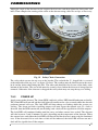
GENERAL CONSTRUCTION
Fig. 13 shows a general view of a complete detector with its mounting bracket.
The detector is of robust construction to allow its use in harsh environments.
The detector comprises a two-part stainless steel ‘spigot-type’ enclosure. Both halves of the
enclosure are guided into the correct position by an alignment pin. The front section of the
enclosure contains the detector optical and electronic sub-assemblies. Mating connectors at the
rear of the front section and on the terminal board mounted in the rear section of the enclosure
provide a means of electrical connection to the installation cables.
The rear enclosure of the FV311 series of detectors is provided with two M20 gland entry holes at
the bottom of the detector. Two 10-way terminal block arrangements are provided for termination
of installation cables.
The rear enclosure of the FV312 series of detectors is provided with a permanently attached cable
sealed in the enclosure. With these detectors, termination of installation cables is made in an
external EExe junction box.
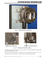
Both types of rear enclosure have a dedicated earthing point on the side of the casting (Fig. 14) to
connect an earth bonding wire from the nearest safety earthing point to the enclosure. Also, a
tagging loop is provided on the side of the rear enclosure to attach a suitable label to identify the
detector on site.
16
SYSTEM DESIGN INFORMATION
DO
N
HE
W
AN
OSIVE GAS AT
MO
EXPL
tyco
FlameVision
FV311SC-N
SP
HE
RE
IS
PR
T
EN
ES
NO
T
O
N
PE
S/No.12365
PATENTED
ATEX
Baseefa07
ATEX0178X
FM
II 2 G D
APPROVED
Ui = 30V
Pi = 10W
IECEx
BAS07.0048X
Ex d IIC
Ex t D A21
o
T135 C
o
o
Ta: - 40 C to + 80 C
o
T100 C
o
o
Ta: - 40 C to + 70 C
o
o
Ta : - 40 C to + 80 C
CI I Div 1 Grp B,C,D
CI II Grp E,F,G CI III
SEAL
CONDUITS
WITHIN 18"
1180
243532
2079801
Ex d IIC T4/T5
DIP A21 IP66/67
T135°C/T100°C
IP66/67
N
TO
5K 0
TYCO TW16 5DB UK
R Q CA
+ 2 (1
UE BLE
: Ta .FT
ING LB
CO ENTR
IES: M2 0 CABLE RAT ) TO 7
VER
0
7
BO LT
S (MIN. GRADE A4
Fig. 13
EARTH BONDING CONNECTION
Fig. 14
m
)
FV300 Detector - General View
TAGGING LOOP CONNECTION POINT
Earthing and Label Fixing Points
A hanging cord enables the two halves of the enclosure to remain attached when opening the
detector during maintenance work.
The front section of the enclosure is attached to the rear section by four captive screws. A seal
provided between the front and rear sections ensures protection to IP66 and IP67.
17
SYSTEM DESIGN INFORMATION
Fig. 15 FV311/FV312 Top Section
Fig. 16
18
FV312 Bottom Section
SYSTEM DESIGN INFORMATION
Fig. 17
FV311 Bottom Section
The front section of the enclosure is fitted with a window guard plate to protect the two detector
viewing windows. A locally formed section of this plate acts as a mirror for the Optical Path
Monitoring test. This plate also contains the mandatory markings required by the Flameproof and
Explosion Proof Regulatory standards (ATEX, IECEx and FM).
The detector may be fitted directly to a suitable surface or an optional adjustable mounting bracket
may be used. An optional weather hood is available for use where protection against extreme
environmental conditions such as hot sun or downpour is needed.
A weather hood is available for use in tropical climates where intense sunlight may occur (Fig. 18).
It also provides protection from rain falling on the window.
19
SYSTEM DESIGN INFORMATION
Fig. 18 FV300 Detector With Weather Hood Fitted
4.4
4.4.1
ENVIRONMENTAL CHARACTERISTICS
GENERAL
The design and construction of the FV300 series detectors are such that they may be used over a
wide range of environmental conditions. Relevant limits are given in Para 4.2.
4.4.2
TEMPERATURE AND HUMIDITY
FV311S/FV312S - models without camera
Operating temperature range:
Storage temperature range:
-40°C to +80°C
-40°C to +80°C
FV311SC(-N)/FV312SC(-N) - models with camera
Operating temperature range:
Storage temperature range:
-10°C to +50°C*
-20°C to +70°C
All models
Relative humidity:
Up to 99% (non-condensing)
Note:
20
* The detector will turn the camera off if the temperature goes outside this range
but fire detection capability is still present when the video is switched off.
SYSTEM DESIGN INFORMATION
4.4.3
VIBRATION AND SHOCK
The FV300 detectors have been designed and tested for vibration and shock and comply with the
requirements of:
EN 54-10, European standard for point flame detectors,
Lloyd’s Register of Shipping (LRS) Test Specification Number 1 (2002),
Det Norske Veritas (DNV) Certification Notes No 2.4 (April 2001) Class A,
Germanischer Lloyd (GL) Rules for Classification and Construction, Test Requirements for
Electrical, Electronic Equipment, Computers and Peripherals (April 2001),
Factory Mutual FMRA 3260, Approval Standard for Radiant Energy-Sensing Fire Detectors for
Automatic Fire Alarm Signalling.
The following maximum levels are applicable:
Operational vibration:
1.24 mm displacement (from 5 Hz to 14.2 Hz)
1.0 g (from 14.2 Hz to 150 Hz)
Operational shock/impact:
20.0ms2
4.4.4
ELECTROMAGNETIC COMPATIBILITY
The FV300 detector is insensitive to normal levels of radio frequency interference. It has been
designed and tested, and complies with the following requirements:
EN 50130-4, the European product family standard for components of fire and
security systems,
VdS 2504 1996-12 (01),
LRS Test Specification Number 1 (2002),
DNV Certification Notes No 2.4 (April 2001), Class A,
GL Rules for Classification and Construction, Test Requirements for Electrical, Electronic
Equipment, Computers and Peripherals (April 2001),
Factory Mutual FMRA 3260, Approval Standard for Radiant Energy-Sensing Fire
Detectors for Automatic Fire Alarm Signalling.
The following maximum levels of interference are applicable:
Radiated radio frequency:
Conducted radio frequency*:
Fast electrical transient burst:
Slow high-energy surge:
Electrostatic discharge:
10V/m (from 80MHz to 2GHz)
30V/m (from 415MHz to 466MHz)
30V/m (from 890MHz to 960MHz)
10V/m (from 150kHz to 100MHz)
± 2kV (applied for 5 minutes)
± 2.4kV
± 8kV (air discharge)
± 6 kV (contact discharge)
*Radio frequency coupled into signalling, d.c. power supply and screen/earthing wires.
The FV300 detector has also been tested for compliance with the radio frequency emission
requirements of EN 61000-6-3 and, hence, meets the European Union EMC Directive 89/336/
EEC. It also complies with the radio frequency emissions requirements of LRS, DNV and GL
Maritime Societies.
21
SYSTEM DESIGN INFORMATION
4.4.5
IONISATION RADIATION
The FV300 detector, like other infrared detectors, is insensitive to X-rays and gamma radiation as
used in non-destructive testing.
The detector will operate normally and will not false alarm when exposed to this type of radiation.
However, long-term exposure to high radiation levels may lead to permanent damage.
4.4.6
CORROSION
The use of a sealed stainless steel 316L enclosure allows the FV300 detector to withstand the
effects of most corrosive substances and gas. In particular, it meets the requirements for sulphur
dioxide (SO2) conditioning in EN 54-10 and exposure to salt mist concentration as specified in
LRS, DNV and GL test specifications for approval of equipment for marine use.
Note:
4.5
Over time, the outer surfaces of the detector may discolour and give an
appearance of being ‘rusty’. This discolouration is caused by the oxidation of
contaminants collected on the surface of the enclosure, especially areas with a
textured finish. It only affects the surface of the material and does not reduce the
thickness or affect the mechanical properties of the enclosure in any way.
FIRE DETECTION CHARACTERISTICS
4.5.1
GENERAL
A large number of fire tests have been carried during the development phase of the FV300
FlameVision detector to determine the response limits. The results of these tests are summarised
below.
4.5.2
FIRE DETECTION RANGE AND RESPONSE TIME
The following table shows the detection range and field of view for the FV300 detectors for a
selection of typical fuels. The FV300 dynamically adjusts to the fire size and does not need
selectable sensitivity levels. These performance figures have been tested and confirmed by FM
Approvals apart from the figure marked †.
Fuel
Size
m2 (ft x ft)
N-Heptane
0.1 (1 x 1)
Petrol
0.1 (1 x 1)
Aviation fuel (JP5)
0.4 (2 x 2)
Alcohol (Methylated spirits)
0.1 (1 x 1)
Diesel
0.1 (1 x 1)
Diesel
Diesel
Methane plume
0.1 (1 x 1)
0.1 (1 x 1)
30 inches
22
Field of View
H: Horizontal
V: Vertical
H: ±45°
V: ±40°
H: ±45°
V: ±35°
H: ±45°
V: ±40°
H: ±45°
V: ±40°
H: ±45°
V: ±30°
H: ±45°
V: ±30°
H: ±45°
V: ±40°
Distance
m (ft)
50 (165)
50 (165)
50 (165)
35 (115)
25 (82) †
24 (80)
15 (50)
20 (64)
SYSTEM DESIGN INFORMATION
The detector range is unaffected by the presence of hot objects (black bodies) within the field of
view.
The typical response time for the detector is less than 12 seconds. The following table shows the
response time for a selection of fuels measured on axis for fully developed fires. These
performance figures have been tested and confirmed by FM Approvals.
Size
m (ft x ft)
0.1 (1 x 1)
0.1 (1 x 1)
0.2 (1.5 x 1.5)
0.1 (1 x 1)
0.4 (2 x 2)
0.1 (1 x 1)
0.1 (1 x 1)
0.4 (2 x 2)
30 inches
Fuel
N-Heptane
N-Heptane
N-Heptane
Petrol
Aviation fuel (JP5)
Alcohol (Methylated spirits)
Diesel
Diesel
Methane plume
4.6
Distance
m (ft)
50 (165)
61 (200)
61 (200)
55 (180)
61 (200)
35 (115)
30 (100)
50 (165)
24 (80)
2
Response Time
Seconds
9
11
7
9
9
11
11
7
18
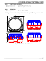
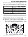
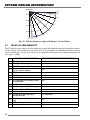
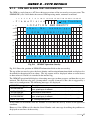
DIRECTIONAL SENSITIVITY
The FV300 FlameVision detector has been designed to achieve constant sensitivity across the field
of view. The relative variation of range with angle of incidence (polar diagrams) is shown in Figs.
19 and 20 for open-air tests using 0.1m2 pan petrol fires.
The continuous line indicates response of the detector within 30 seconds (as required by both
FMRC 3260 and EN 54-10), with the detector at the minimum alarm delay. The dotted line
indicates response of the detector within 12 seconds, for the minimum alarm delay.
Note:
When test fires are carried out outdoors, the response of the detector can be
significantly affected by wind as the flame may be blown horizontally outside its
field of view, at least during part of the test. In effect, the detector is seeing only
a portion of the total radiant energy from the fire during a given period. This effect
is accentuated, as the fire gets closer to the 45° position.
90
80
DETECTOR
o
90
o
80
o
o
0.20
70 o
70
o
0.40
60
o
60
o
0.60
50
45
o
50
0.80
o
45
o
o
1
40
o
Fig. 19
30
o
20
o
10
o
o
0
10
o
20
o
30
o
40
o
Relative Range vs Angle of Incidence - Horizontal Plane
23
SYSTEM DESIGN INFORMATION
DETECTOR
45
40
o
o
0.20
30
o
0.40
15
o
0.60
0
o
0.80
15
1
45
Fig. 20
4.7
o
40
o
30
o
o
Relative Range vs Angle of Incidence - Vertical Plane
FALSE ALARM IMMUNITY
The FV300 has been subjected to the following stimuli that might be considered potential sources
of false alarms. Unless otherwise specified, tests were performed at a minimum distance between
source and detector. Steady state sources were chopped at both regular and random frequencies in
the range 0 - 10Hz.
1
2
3
4
5
6
7
8
9
10
11
12
13
14
15
16
24
FALSE ALARM SOURCE
Sunlight
Sunlight with rain
150W tungsten filament lamp
Fluorescent lamp (bank of 4 x
32 W circular lamps)
70W sodium lamp
125W mercury vapour lamp
4.8kW IR radiant heater
2 x 500W quartz halogen lamps
(unshielded)
2 kW fan heater
Car headlights (60W halogen)
Car headlights (60W xenon)
Lighted cigarette
Grinding of ducting metal
(angle grinder)
Electric arc welding (2.5mm
rod)
MIG welding
Vibration
IMMUNITY DISTANCE RESPONSE (m)
No response
No response
1m
1m
1m
1m
1m
2m
1m
No response
4m
No response
No response
4m
1m
N/A
SYSTEM DESIGN INFORMATION
4.8
4.8.1
DESIGN OF SYSTEM
GENERAL
Using the information given in Sections 4.5 and 4.6, it is possible to design a flame detection
system having a predictable performance. Guidelines on the application of the above data, and on
siting of detectors, are given in the following paragraphs.
CAUTION:
THE GUIDELINES GIVEN HERE CANNOT CATER FOR ALL
EVENTUALITIES THAT MAY BE ENCOUNTERED ON A SITE.
4.8.2
USE OF FIRE TEST DATA
It has been explained in Sections 4.5 and 4.6 that the sensitivity of the detector is most easily
specified in terms of its response to well-defined test fires. Tests are conveniently carried out using
a 0.1m2 pan. Sensitivity to other pan areas is estimated from field trial results.
4.8.3
DETERMINING THE NUMBER OF DETECTORS
It will be clear that the number of detectors required for a particular risk will depend on the area
involved and the fire size at which detection is required. Large areas or small fires require large
numbers of detectors.
There are as yet no agreed ‘rules’ for the application of flame detectors and the overall system
sensitivity must, therefore, be agreed between the installer and the end user. Once this agreement
has been reached the system designer can determine the area covered by each detector using a
scaled plot based on Figs. 20 and 21 and the fire test data. This plot is best drawn to the same scale
as the site plan so that direct superposition can be used to determine detector coverage.
In carrying out the design, certain factors should be kept in mind:
a) Mounting the detectors on the perimeter of the area and pointing into the area will
give the best coverage for area rather than spot protection.
b) As the FV300 detectors are line of sight detectors any object within the detector’s
field of view will cause a ‘shadow’ in the protected area. Even small objects close
to the detector can cause large shadows.
c) The detector should not be mounted in such a position that water will collect on
the window.
d) The detectors are passive devices and will not react with one another. They may
therefore be positioned with their fields of view overlapping.
25
SYSTEM DESIGN INFORMATION
4.9
4.9.1
APPROVALS, COMPLIANCE WITH STANDARDS AND PATENTS
FLAMEPROOF CERTIFICATION
All models of the FV300 FlameVision detectors are flameproof and are certified to the ATEX
directive and IECEx by Baseefa.
The detectors are designed to comply with EN60079-0: 2006, EN60079-1: 2004, EN600797:2006, IEC61241-0: 2006 and IEC61241-1: 2004.
They are certified:
ATEX code:
II 2 G D
Certificate:
Baseefa07ATEX0178X
IECEx/Cenelec code: Ex d IIC T4 ExtD A21 IP66/67 T135°C (-40°C ≤ Ta ≤+80°C) or
Ex d IIC T5 ExtD A21 IP66/67 T100°C (-40°C ≤ Ta ≤+70°C)
Certificate:
BAS07.0048X
These detectors are designed and manufactured to protect against other hazards as defined in
paragraph 1.2.7 of Annex I1 of the ATEX directive 94/9/EC.
The one special condition of the certification is that, when using the fitted cable from the FV312
series detectors, this cable must be suitably terminated and protected from impact. See the
installation section for installation recommendations.
4.9.2
FM APPROVALS
The detectors are also designed to comply with the requirements of Factory Mutual FMRC 3600
and FMRC 3615 for use in hazardous area locations Class I, Div 1, Group B, C, D and Class II
Group E, F G and Class III.
The FV300 FlameVision detectors have been designed to and comply with requirements of Factory
Mutual FMRC 3260, the approval standard for Radiant Energy-Sensing Fire Detectors for
Automatic Fire Alarm Signalling.
4.9.3
CSA APPROVALS
The FV311S, FV311SC and FV311SC-N are approved by CSA for use in Canada in both gas and
dust environments. They are certified:
Ex d IIC T4 DIP A21 IP66/67 T135°C; -40°C ≤ Ta ≤ 80°C
Ex d IIC T5 DIP A21 IP66/67 T100°C; -40°C ≤ Ta ≤ 70°C
Certificate:
Note:
26
2079801
For CSA compliance the detectors must be powered from a class 2 certified PSU.
SYSTEM DESIGN INFORMATION
4.9.4
CONSTRUCTION PRODUCTS DIRECTIVE
The FV300 range of flame detectors comply with and are manufactured to the requirements of the
Construction Products Directive. The detectors carry the CE and CPD marks.
0786
Tyco Safety Products
Dunhams Lane
Letchworth SG6 1BE
UK
10
0786-CPD-20929
EN 54-10: 2002 + A1: 2005
FV311S
Class 1 IR point flame detector for use in fire detection and alarm systems
FV311SC-N
Class 1 IR point flame detector for use in fire detection and alarm systems
FV311SC
Class 1 IR point flame detector for use in fire detection and alarm systems
FV312S
Class 1 IR point flame detector for use in fire detection and alarm systems
FV312SC-N
Class 1 IR point flame detector for use in fire detection and alarm systems
FV312SC
Class 1 IR point flame detector for use in fire detection and alarm systems
Installation/Service Instructions:
120.415.886
Fig. 21
4.9.5
MARKING
All the markings required by the various approval bodies are on the front plate (see Fig. 22) with
the exception of:
a) The Year of Manufacture/Construction which is stated on a label affixed to the
rear of the front case assembly. This is only visible when the front case assembly
is unbolted from the base assembly.
b) The ‘WEE’ mark, VdS EN54-10 approval and CPD approval which are on a label
affixed to the backbox. This is only visible when the front case assembly is
unbolted from the base assembly.
27
O
N
PE
E
WH
N
NA
OSIVE GAS AT
MO
EXPL
SP
tyco
FlameVision
FV311SC-N
DO
IS
PR
T
S/No.XXXXX
HE
RE
EN
ES
NO
T
SYSTEM DESIGN INFORMATION
PATENTED
ATEX
Baseefa07
ATEX0178X
FM
II 2 G D
APPROVED
IECEx
Ui = 30V
Pi = 10W
BAS07.00488X
Ex d IIC
Ex t D A21
o
T135 C
o
o
Ta: - 40 C to + 80 C
o
T100 C
o
o
Ta: - 40 C to + 70 C
o
o
Ta : - 40 C to + 80 C
CI I Div 1 Grp B,C,D
CI II Grp E,F,G CI III
SEAL
CONDUITS
WITHIN 18"
1180
IP66/67
243532
2079801
Ex d IIC T4/T5
DIP A21 IP66/67
T135°C/T100°C
)
m
TO
K 0N
5
1
2
R Q CA
(
+
TYCO TW16 5DB UK
UE BLE
: Ta .FT
I NG 7 LB
ENT
CO
T
A
R
R
IES: M20 CABLE
VER
TO
BOLT
-70)
S (MIN. GRADE A4
Fig. 22
4.9.6
View of Detector Label with Regulatory Markings
PATENTS
The FV300 design and manufacture is covered by the following patents licensed from InfraRed
Integrated Systems Limited:
UK patents:
European patents:
US patents:
Hong Kong patent:
28
GB 2 353 856, GB 2 353 424 and GB 2 372 317
EU 1 079 349 and EP 1 233 386
US 6 528 788, US 6 476 859 and US 6 818 893
HK 1 050 951
OPERATION
5.
5.1
OPERATION
INDICATORS
The FV300 FlameVision detector has a red LED for reporting alarms and a yellow LED for
reporting faults. Both LEDs are located in the camera window, see Fig. 23. The alarm LED turns
on to report an alarm. The fault LED turns on to report hardware faults or is flashed to show an
OPM ‘dirty window’ fault.
The red LED will turn on briefly when an alarm test is performed.
WINDOW TEST
LAMPS UNDER
RELECTOR
IR RECEIVER
RED LED (ALARM)
YELLOW LED (FAULT)
SAPPHIRE
WINDOW
REINFORCED
GLASS
WINDOW
Fig. 23
5.2
LED Location
POWER UP AND INITIALISATION
On power up, the detector performs a complete self-test to check all functions. The alarm (red) and
fault (yellow) LEDs flash briefly as power is applied. The alarm LED then turns off and the fault
LED remains on for the duration of the self-tests. If a fault is detected the LED remains on and the
fault signalled as below.
With the self-tests complete, the array is now allowed to warm-up and settle. During this time the
fault LED will flash rapidly (about 3 times per second). When the array is ready, the fault LED will
turn off. This will take about 5-20 minutes. If the array does not settle within 30 minutes then a
fault will be indicated and signalled.
Note:
5.3
The detector cannot detect alarms, do OPM tests or alarm tests whilst the array
is settling.
ALARM AND PRE-ALARM INDICATION
The alarm (red) LED will illuminate when the detector is in alarm. It will remain illuminated until
the reason for the alarm has cleared (non-latching mode) when it will turn off. In latching mode
the detector will also need to be reset, see below.
The alarm (red) LED remains off when the detector enters the pre-alarm state.
The alarm LED is located in the camera window, see Fig. 23.
The remote LED output will be activated when the alarm LED is on to give an external alarm
indication.
29
OPERATION
5.4
ALARM SIGNALLING
The FV300 detector has a number of external interfaces. An alarm condition is signalled on all of
these interfaces as follows:
Alarm relay:
4-20mA:
Modbus:
Video:
The alarm relay will close.
The current (source or sink) becomes 17mA
The alarm bit is set in the status register and is available at the next read of the
unit.
An alarm banner will be superimposed on the CCTV image along with a target
showing the location of the alarm.
Each interface will remain activated until the reason for the alarm has cleared (non-latching mode)
when it will turn off. In latching mode the detector will also need to be reset, see below.
5.5
PRE-ALARM SIGNALLING
The detector enters a pre-alarm state when it detects a source within the field of view that has not
yet reached the alarm threshold. The source may be worthy of investigation.
The FV300 detector has a number of external interfaces. A pre-alarm condition is signalled on
some of these interfaces as follows:
Alarm relay:
4-20mA:
Modbus:
Video:
No change, the alarm relay will remain open.
The current (source or sink) becomes 11.5mA
The pre-alarm bit is set in the status register and is available at the next read
of the unit.
No change.
The pre-alarm condition will escalate into a full alarm if the source is determined to be a fire. Or
it will clear if the source is removed.
5.6
FAULT AND OPM INDICATION
The fault (yellow) LED will illuminate when the detector has detected a hardware fault. It will
remain illuminated until the reason for the fault has cleared (non-latching mode) when it will turn
off. In latching mode the detector will also need to be reset, see 5.9.
If the regular OPM test determines that the window is dirty then the fault (yellow) LED will flash
approx.(1 second, 1 second off). If the window is found to be completely obscured it is treated as
a hardware fault and the fault LED is illuminated.
The fault LED is located in the camera window, see Fig. 23.
5.7
SERVICE MODE INDICATION
The detector is put into the Service Mode when it is connected to a PC for configuration or
diagnostics. When in this mode, the fault (yellow) LED wil flash slowly (2 seconds on, 2 seconds
off).
Note:
30
In Service Mode the detector is disabled and will not detect a fire.
OPERATION
5.8
FAULT AND OPM SIGNALLING
The FV300 detector has a number of external interfaces. A fault condition is signalled on these
interfaces as follows:
Fault relay:
4-20mA:
Modbus:
Video:
The fault relay will open. (Hardware, window and OPM faults)
The current (source or sink) become 0mA for hardware and window
faults or 2mA for OPM faults.
The appropriate fault bit will be set in the status register and is available
at the next read of the unit. Hardware faults, window obscured and
window dirty are separately identified.
A fault banner will be superimposed on the CCTV image with an
information field to specify the fault type.
Each output will remain activated until the reason for the fault has cleared (non-latching mode)
when it will return to normal status. In latching mode the detector will also need to be reset, see
section 5.9.
5.9
DELAY TO ALARM
The FV300 processes the array and sensor signals to identify a potential alarm event twice a
second. The detector takes 9 cycles, 4.5 seconds, to confirm that there is an event to report. The
detector considers each report and will indicate and signal an alarm if several alarm event reports
are produced within a time window. The number of reports to consider is selectable and defines the
response time. The detector response time consists of the initial 4.5 seconds followed by the
selectable delay.
The FV300 detector provides 4 selectable alarm response times. These are set on the DIP switches,
see Section 7.2.2.
SW
1-2
SW
1-3
Delay
Description
0
1
SHORT
0
0
MEDIUM
(Default)
1
0
LONG
1
1
EXTRA LONG
Alarm / Prealarm
ON condition
1.5 seconds over threshold
in any 4 second period
4.5 seconds over threshold
in any 8 second period
9 seconds over threshold in
any 12 second period
12 seconds over threshold in
any 15 second period
Alarm / Prealarm
OFF condition
10 seconds under
threshold
10 seconds under
threshold
12 seconds under
threshold
15 seconds under
threshold
The default setting requires that in an 8 second window the event should be reported for at least 4.5
seconds to put the detector into alarm. This gives an overall response time of 9 seconds. The
minimum time from the presentation of a detectable fire to activation of the outputs is 6 seconds
(short delay). The alarm delay response times are also used for the pre-alarm response.
The selected response time also defines the alarm clearing time in non-latching mode. An alarm is
cleared when a number of reports of no alarm are produced. The default setting requires that 20
reports (10 seconds) are detected. Thus a detector will remain in alarm for at least 10 seconds.
31
OPERATION
5.10 RESETTING ALARM AND FAULT CONDITIONS
In latching mode, alarms and faults will continue to be indicated and signalled, even if the original
cause has been removed. The detector needs to be reset to clear the condition. The detector can be
reset by activating the wired input or remotely using the walk-test trigger tool. During the reset the
indicators and outputs will be turned off but if the alarm or fault is still present the condition will
be re-established. The detector will perform re-tests if necessary, such as an OPM test, to determine
if faults have cleared.
5.11 SELF-TEST
The FV300 detector performs a regular self-test of the electronics and monitors the interfaces in
the detector. This occurs automatically at pre-set timed intervals and does not disturb the normal
operation of the detector. If a fault is detected it will be indicated and signalled as described in
section 5.7.
5.12 OPTICAL PATH MONITORING (OPM) TEST
The FV300 detector can check the cleanliness of the window used by the array and other optical
sensors. The detector flashes a lamp that radiates IR at the same wavelength used for fire detection
for about 5 seconds. The lamp shines onto a mirror that reflects the energy back through the
window onto a specific section of the array. The detector analyses the reflected signal to assess if
the window is dirty.
The OPM test can be initiated manually, on demand, using the walk-test trigger tool, the walk-test
wired input or from the field bus interface. When the OPM test is activated manually, a single test
is performed and the result reported on the indicators and outputs. If the window is considered to
be dirty or obscured then an OPM fault is reported. The fault will be cleared when the window is
cleaned and the test re-run to give a clean result. Requests for a manual OPM test will be ignored
if the detector is in alarm, pre-alarm or performing an alarm test.
Alternatively, the detector can be configured to perform the OPM test automatically at regular
intervals by setting a DIP switch (OPM Man/Auto). The default is automatic OPM testing. The
time interval can be adjusted using the PC configuration tool. The default OPM test interval is
every 20 minutes. The first OPM test will be made 20 minutes (or the configured time) after powerup. The regular OPM test will be delayed if the detector is in alarm, pre-alarm or performing an
alarm test. A manual OPM test can be initiated at any time when the detector is in automatic OPM
mode and will produce an immediate test result reported on the indicators and outputs as described
above.
If the automatic OPM test detects the dirty condition (5-50%) for 20 successive tests then an OPM
fault is reported. If the window is considered to be obscured (<5%) then the OPM test interval
reduces to 5 minutes and if the window remains obscured for 5 further tests then an OPM fault is
reported. The obscured condition is thus detected and reported much faster. Either fault will be
cleared when the window is cleaned and the test re-run to give a clean result. The test can be
activated manually after cleaning rather than waiting for the next timed automatic test.
The detector is fitted with 2 lamps. These are used alternately to maximise their lifetime. If a lamp
should fail then the detector can continue using the one lamp without reporting a fault. The failure
of both lamps will be reported as a hardware fault.
32
OPERATION
5.13 WALK-TEST (ALARM TEST)
WARNING:
THE DETECTOR OUTPUTS WILL BE ACTIVATED DURING A
WALK-TEST. DISCONNECT ALL EXTINGUISHING SYSTEMS OR
EXTERNAL DEVICES THAT SHOULD NOT BE ACTIVATED DURING A TEST.
The FV300 detector has a built in alarm test facility. The lamps used for the OPM test are flashed
in a pattern to simulate a flame. The IR output from the lamps reflects off the mirror and onto the
array. The lamp signal is then processed using the same algorithms as used for external sources to
produce an alarm which is then indicated on the LED and signalled on all external interfaces. This
is a true test of the ability of the detector to detect a fire.
The alarm test can be triggered from the wired walk-test input or remotely using the walk-test
trigger tool.
When the test is started, a lamp will flash until an alarm is detected, typically after 10 seconds. The
lamp will then turn off. The detector will indicate the alarm on the LED and activate all outputs as
described above. The outputs will remain active for the duration of the alarm hold time set on the
DIP switches (10-15 seconds).
If the flashing lamps do not trigger an alarm then a hardware fault is reported and the lamps are
turned off.
Note:
The alarm test cannot be performed whilst the array is settling or whilst the
detector is in alarm, pre-alarm or performing an OPM test.
The alarm test may not generate an alarm if a strong black body source is in the field of view or
modulated sunlight falls onto the detector.
5.14 VIDEO DISPLAY
The FV300 can overlay alarm and fault information on top of the camera picture (CCTV output).
The overlay is normally enabled but can be disabled by configuration. If no camera is fitted then
the overlay can be viewed on a plain colour background. This is enabled by configuration.
If an alarm is detected, the overlay will flash an alarm message and display a box drawn around
the alarm source to show the location within the field of view.
Faults are individually identified on the display as shown in Annex B.
33
INSTALLATION
6.
INSTALLATION
6.1
GENERAL
The FV300 Series detectors may be surface mounted or may use the FV300 adjustable mounting
bracket.
On the FV311 series, all electrical connections are made via terminal blocks inside the detector
rear housing. Two 20mm cable entries are provided. On the FV312 series, electrical connections
are made through the FlameVision Exe junction box, selecting the appropriate circuits required.
Guidance on mounting and wiring the detectors is given below.
6.2
6.2.1
MOUNTING A DETECTOR
GENERAL
The location of each detector should have been determined at the system design stage according to
the principles detailed in the System Design Information section and marked on the site plan.
The actual mounting position must, however, be decided during the installation and in choosing the
position, the following principles together with the original system requirements should be
followed.
6.2.2
CHOICE OF MOUNTING POSITION
The following points must be observed when choosing the mounting position:
a) The detector should not be installed where it may be subject to mechanical or
thermal stresses or where it may be attacked by existing or foreseeable aggressive
substances.
b) The detector must be positioned such that a clear line of sight is provided to all
parts of the risk area. Roof trusses, pipework, supporting columns etc. in front of
the detector can cause significant shadowing and should be avoided.
c) If supervision of an area immediately below the detector is required, it is essential
that the angle between the detector and the horizontal is not less than 50°.
d) The detector should not be sited in a position where it will be continuously
subject to water drenching. The FlameVision Weather hood should be use to
protect the detector from heavy downpours that may be frequent in certain
climates.
e) In outdoor installations, in areas of high solar radiation, some form of sunshade
is recommended to prevent excess heating of the detector. The FlameVision
Weather hood can provide protection against direct sun.
f) The detector should not be sited in a position in which it will be subject to severe
icing.
g) Where a certain amount of icing or water condensation can occur, it is
recommended that the window de-mister be selected. See the System Deign
Information section for additional power requirement.
34
h) The detector must be mounted on a stable structure that is readily and safely
accessible for maintenance staff.
INSTALLATION
i) Preferably, the detector should be mounted such that the face is tilted downwards
to prevent water collection and lessen the settlement of particle deposits on the
window.
CENTRE OF DETECTOR
FIELD OF VIEW
INCORRECT METHOD
CEN
FIE TRE O
LD
OF F DET
ECT
VIE
W
OR
PREFERRED METHOD
Fig. 24
Detector Orientation Relative to Horizon
The detector mounting bracket must be secured to the mounting surface with four M8 Bolts, studs
or screws at the fixing centres shown in the orientation shown in Fig. 12. A drilling template is
provided to allow optimum selection of the fixing centres. The detector is to be secured to the
bracket using the three M6 studs with nuts and locking washers provided.
The FV300 Series may be operated in any position but the mounting point must obviously be
chosen to allow sufficient clearance for adjustment of the angle and must also allow space for the
cable assembly. A clearance of 200mm, in all directions, from the fixing point will normally be
sufficient to allow the full range of adjustment. (Fig. 24 refers).
Alternatively, the detector may be secured directly to the fixing surface with three M6 bolts, studs
or screws at the fixing centres shown in Fig. 11. The surface chosen for the mounting should be
flat over the area of the bracket to ensure a stable fixing.
35
INSTALLATION
6.2.3
MOUNTING THE FV312 SERIES DETECTOR WIRING
In addition to the installation recommendations given in 6.2, the following applies when installing
FV312 series detector:
a) The detector in-built cable should interface with the field cable via an EExe
junction box with EExe cable entry glands suitable for the size of cable used. The
FlameVision EExe has been designed to provide a ready-made solution to
interfacing with any of the inputs/outputs of the FV300 detector.
b) It is a requirement of the ATEX/IECEx approval that the cable between the
detector and the EExe junction is protected against mechanical damage. For this
purpose the FV312 has been designed to mate with a flexible metal conduit. It is
recommended that the Kopex Liquid Tight LT-H 316 stainless steel 20mm
conduit system is used (Kopex FSH04). This conduit uses a Type H flame
retardant covering to give a high resistance to oils and chemicals. A connector kit
(Kopex KSO/1005) is available to terminate the conduit and couple directly onto
the FV312 enclosure.
c) The selected mounting position for the detector must take into account the siting
of the EExe junction box. The detector is supplied with a maximum of 1m cable
and allows sufficient slack in the flexible conduit for adjusting the orientation of
the detector when using the adjustable mounting bracket.
6.3
DETECTOR WIRING
6.3.1
GENERAL
The wiring between the detectors and control equipment must provide the required degree of
mechanical protection but be sufficiently flexible to allow the detector alignment to be adjusted to
suit the area protected.
To meet the mandatory EMC requirements of EN 61000-6-3 for emissions and EN 50130-4 for
susceptibility, it is necessary to terminate the armouring / screening of the cable through 360° at
the detector cable gland and ensure that the detector is solidly bonded to a good local earth.
Fig. 25 through to Fig. 27 show wiring diagrams for the FV311 series of detectors. The FV312
series detectors are wired in the same way. The cores are listed in Table 5.
Notes:
1) If FV300 detectors are installed in dust risk environments then the walk-test wired
input should be used. The WT300 is not approved for dust risk environments.
2) It is recommended that the RS485 Configuration port from the FV300 is wired
back to a central point to support remote configuration and diagnostics. The
configuration port can be wired as a bus connecting up to 16 detectors. An
RS485 to PC interface (RS232 or USB) is required that can communicate at up
to 38,400 baud with direction controlled by the RTS line.
36
INSTALLATION
6.3.2
RECOMMENDED CABLE TYPE
6.3.2.1
CONVENTIONAL CIRCUITS
The cable selected for interconnection to the control equipment should meet the requirements of
any national codes (eg, BS5839) or relevant approval bodies. Cables should not normally have a
cross sectional area of less than 1mm2 for solid conductors or 0.5mm2 for stranded conductors.
Cable temperature rating must allow for an increase in the enclosure temperature of 25° above
ambient.
The following cables are generally recommended for use:
a) Shipwiring Cable to BS6883.
b) PVC insulated cable to BS6004, run in screwed steel conduit to BS4568 Part 1.
c) 16/0.2mm twin or multi-core cable to DEF Standard 61-12 (Part 5), run in
screwed steel conduit to BS4568 Part 1.
d) PVC insulated cable to BS6231, Type BK, run in screwed steel conduit to
BS4568 Part 1, or plastic conduit to BS4607, or trunking. (Conductors having a
cross-section of less than 1mm2 should not be drawn into conduit but can be run
in trunking).
e) Mineral insulated cable, twin or multi-core, to BS6207 Part 1, with all cable
terminations and fittings supplied by the manufacturer of the cable.
f) PVC insulated, PVC inner sheathed, steel wire armoured and PVC oversheathed
cable to BS6346.
g) Cabling and conduit for flameproof circuits must comply with BS EN6007914:2003.
h) For the FV312 series, the EExe junction box must be mounted within 0.6m of the
detector.
6.3.2.2
CABLE ROUTING
All interconnecting cables should be run in conduit or trunking which is reserved exclusively for
fire alarm circuits. Where such separation is not possible MICC cable should be used.
Particular care must be taken to ensure that detector wiring is not run close to a.c. power circuits.
6.3.3
CABLE ENTRY SEALING
CAUTION:
CABLE GLANDS AND STOPPING PLUGS MUST BE SUITABLY SEALED TO
PREVENT THE INGRESS OF MOISTURE.
Only cable glands incorporating an inner cable seal should be used. In exposed outdoor areas, it
is recommended that a shroud be fitted over the cable glands. Cable glands should also be sealed
to the detector housing by fitting a nylon washer between their flange and the housing.
In applications where the ambient temperature is expected to be 40oC or higher, cable glands with
a silicon inner seal must be used and, when fitted, the shroud must be made of CR rubber.
37
INSTALLATION
The use of stopping plugs with a mushroom head and integral ‘O’ ring is recommended.
The glands/stopping plugs should be hand-tightened with the addition of, at least, a further 1/4 turn
applied by spanner or other suitable tool.
Where it is not practicable to use a nylon gland washer or where an anti-seizing union is required,
the following alternative methods may be used:
a) The thread of cable glands/stopping plugs may be sealed using PTFE tape or
other jointing putty or mastic.
b) For Flameproof applications the threads of the flameproof glands/stopping plugs
may be sealed using any non-setting grease or putty as described in BS EN
60079-14 : 1997.
PBC BA 200 loaded mineral oil based grease is a suitable compound and is
available in 100g tubes (Stock Code No. 517.001.250).
38
Fig. 25
CONFIGURATION/
DIAGNOSTICS
ACCESS*
-VE
+VE
BALUN
10
24V
4 - 20
0v
0v
FB+
FBEXC+
EXCVID+
VID-
RS485
INTERFACE
OPTIONAL VIDEO OUTPUT
TB1
S300 RELAY / 4 - 20mA
FIELDBUS TERMINAL PCB
E
O
L
24V
WT
0V
FLT
FLTC
ALED
ALM
ALMC
SCRI
R SCRO
20
ALARM
TEST
RESET
4k7
NOTE: POWER DISIPATION OF
MONITORING CIRCUIT
NOT TO EXCEED 1W
TO
MONITOR
CIRCUIT
TB2
1k8
WINDOW
TEST
15k
6.3.4
CONTROL
EQUIPMENT
* IT IS RECOMMENDED THAT AN
RS485 CONNECTION IS PROVIDED
TO CONNECT TO A PC FOR REMOTE
CONFIGURATION AND DIAGNOSTICS
INSTALLATION
FLAMEPROOF WIRING
Cabling and conduit systems must comply with BS EN 60079-14 : 1997.
Relay Wiring Diagram
39
40
Fig. 26
4 - 20mA
-VE
+VE
PLC
4-20mA Output Wiring Diagram
TB1
10
24V
4 - 20
0v
0v
FB+
FBEXC+
EXCVID+
VID-
S300 RELAY / 4 - 20mA
FIELDBUS TERMINAL PCB
RS485
INTERFACE
OPTIONAL VIDEO OUTPUT
CONFIGURATION/
DIAGNOSTICS
ACCESS*
BALUN
* IT IS RECOMMENDED THAT AN
RS485 CONNECTION IS PROVIDED
TO CONNECT TO A PC FOR REMOTE
CONFIGURATION AND DIAGNOSTICS
24V
WT
0V
FLT
FLTC
ALED
ALM
ALMC
SCRI
SCRO
20
TB2
ALARM
TEST
1k8
RESET
4k7
WINDOW
TEST
15k
INSTALLATION
CONFIGURATION/
DIAGNOSTICS
ACCESS*
RS485RS485+
-VE
+VE
PLC
BALUN
TB1
10
24V
4 - 20
0v
0v
FB+
FBEXC+
EXCVID+
VID-
RS485
INTERFACE
OPTIONAL VIDEO OUTPUT
* IT IS RECOMMENDED THAT AN
RS485 CONNECTIONIS PROVIDED
TO CONNECT TO A PC FOR REMOTE
CONFIGURATION AND DIAGNOSTICS
S300 RELAY / 4 - 20mA
FIELDBUS TERMINAL PCB
24V
WT
0V
FLT
FLTC
ALED
ALM
ALMC
SCRI
SCRO
20
TB2
ALARM
TEST
1k8
RESET
4k7
WINDOW
TEST
15k
INSTALLATION
Fig. 27 Field Network Wiring Diagram
41
INSTALLATION
6.4
INITIAL WIRING CHECK
After installing the wiring as detailed above and before connecting any detectors or end-of-line
devices, the following tests should be carried out.
6.4.1
CONTINUITY TESTS
To check continuity proceed as follows:
a) Short-circuit + to + and - to - at each detector terminal block.
b) Short-circuit the pair at the end furthest from the control equipment.
c) Using an ohmmeter set to its lowest range, check the loop resistance at the control
equipment end.
d) If the reading obtained is less than 50 ohms record the reading obtained and
proceed to Para 6.4.2.
e) If the reading obtained is greater than 50 ohms locate and rectify continuity faults
by quartering the system.
6.4.2
INSULATION TESTS
To check the insulation proceed as follows:
a) Using an ohmmeter set to its highest range, check the resistance between the
circuit and earth.
b) If the reading obtained is greater than 1 megohm record the reading and proceed
to c), otherwise locate and rectify the earth fault.
c) Remove the short-circuit at the end furthest from the control equipment.
d) Measure the resistance between the zone conductors.
e) If the reading obtained is greater than 1 megohm record the reading, otherwise
locate and rectify the insulation fault.
On completion of all tests to ensure no moisture ingress to the detector during the time between
Installation and Commissioning, fit the weatherproof cover Fig. 28. Ensure that the ‘O’ ring
supplied is fitted to the cover. Securely tighten the four M6 x 20mm hex head screws to retain the
cover.
CAUTION
THE FITTING OF THIS TEMPORARY
WEATHERPROOF COVER DOES NOT CONSTITUTE
COMPLETION OF THE CERTIFIED ASSEMBLY
DO NOT CONNECT POWER
FlameVision
Fig. 28
42
Temporary Cover
COMMISSIONING
7.
COMMISSIONING
7.1
SYSTEM CHECKS
Before connecting the zone wiring to the control equipment or to the detectors, a general inspection
of the system should be carried out. In particular, the positions of the detectors should be checked
to ensure that the requirements given in the System Design and Installation sections are met.
When the system wiring has been successfully tested and the control equipment commissioned, the
detector electronic assemblies may be fitted. Set the Remote Configuration (Table 3), Delay
Options (Table 4), Alarm Latching (Table 5), Fault Latching (Table 6) and OPM Inhibit (Table
7). The selectins should be recorded in Annex C for future checking during service and
maintenance operations.
7.2
SWITCH AND HEADER SETTINGS
The FV300 FlameVision detectors are very flexible and can be configured for a wide range of
applications. For ease of installation the most common, primary, options are available on DIP
switches located on the back of the detector. Advanced options, such as masking, and entering
location information for the video display are set using the PC configuration tool.
SWITCH LOCATION
4-20mA
SINK
Fig. 29
7.2.2
1
ON
ON
4-20mA
SOURCE
4-20mA MODE
OFF
SW2
SW1
CONFIGURATION
7.2.1
Switch Location
CONFIGURATION DIP SWITCHES (SW1)
The primary configuration options can be set on DIP switches located on the back of the detector,
see Fig. 29. The switch settings are described in Table 2. The default, supplied, setting is all
switches off.
43
COMMISSIONING
Switch
1-1
Action
Function
Off (Default)
On
Ignore DIP switch settings Use DIP switch settings
Remote Configuration(*) (Use programmed settings)
1-2
Refer to Table 3 Delay Options
Alarm Delay
1-3
1-4
Reserved
1-5
Alarm Latching
Latching
Set in Off position
Non-Latching
1-6
Fault Latching
Non-Latching
Latching
1-7
Window Heater
Off
On
1-8
OPM Man/Auto
Automatic
Manual
Table. 2
Configuration DIP Switches
Notes:
1) (*) When switch 1-1 is turned off (default) then DIP switches 2 to 8 are ignored
and all detector settings must be made using the PC configuration tool. If switch
1-1 is on, then the primary options are set by the DIP switches and can be
supplemented by advanced options set using the PC configuration tool.
2) For detectors with V1.001 software, when the DIP switches are active the action
of switch 5, Alarm Latching, is inverted (Off = Alarm Latching Disabled, On =
Alarm latching enabled).
3) The detector is supplied with the default configuration shown in Table 2.
SW
1-2
SW
1-3
Delay
Description
Alarm / Prealarm
ON condition
Off
On
SHORT
1.5 seconds over threshold 10 seconds under
in any 4 second period
threshold
Off
Off
MEDIUM (Default)
4.5 seconds over threshold 10 seconds under
in any 8 second period
threshold
On
Off
LONG
9 seconds over threshold
in any 12 second period
On
On
EXTRA LONG
12 seconds over threshold 15 seconds under
in any 15 second period
threshold
Table. 3
7.2.3
Alarm / Prealarm
OFF condition
12 seconds under
threshold
Delay Options
4-20mA MODE SWITCH (SW2)
The 4-20mA output can operate in either a source or sink mode. This is selected on switch SW2,
see Fig. 29.
44
TB1
Fig. 30
10
24V
4 - 20
0v
0v
FB+
FBEXC+
EXCVID+
VID-
24V
WT
0V
FLT
FLTC
ALED
ALM
ALMC
SCRI
SCRO
20
TB2
TB2
ALARM
CONTACTS
CON4
CON3
FAULT
CONTACTS
(N/O)
THE LINKS MUST BE FITTED FOR THE OUTPUT TO OPERATE
17 & 18 CONNECTED IF DETECTOR NOT IN ALARM (N/C)
17 & 18 CONNECTED IF DETECTOR IN ALARM
(N/O)
14 & 15 CONNECTED IF DETECTOR OK
14 & 15 CONNECTED IF DETECTOR IN FAULT (N/C)
POSITIONS
NORMALLY
USED
7.2.4
S300 RELAY / 4 - 20mA
FIELDBUS TERMINAL PCB
COMMISSIONING
RELAY CONTACT HEADER SETTINGS
The fire and fault relays can be used as either normally closed or normally open contacts. The
contacts are selected by fitting links to CON3 and CON4 on the terminal board, see Fig. 30. The
links must be fitted for the output to operate.
Header Settings on Terminal Board
45
COMMISSIONING
7.2.5
ADVANCED CONFIGURATION OPTIONS
The advanced configuration options are set using the PC configuration tool which connects to the
detector using an RS485 link via an interface unit. The following options can be set using the tool:
•
•
•
•
•
•
•
Primary options: Options available on DIP switches can alternatively be set by
configuration tool (need to set a DIP switch to select this option).
OPM timing: Set time interval for regular OPM test.
Video output mode: Select what information is overlaid on camera image
Video information: Enter and edit detector location and identity information that
can be overlaid on camera image
Select logging options: Select which events and information are logged by the
detector
Field network parameters: Enter and edit network settings such as baud rate,
addresses, etc.
Alarm Mask: Define masked area in field of view and masking options
The configuration tool can also be used to view internal parameters and for diagnostics by
extracting and processing log data stored in the detector. Further details on the settings and how to
use the tool for diagnostics are covered in the PC300 help file.
46
NOTE 1
ALARM N/O
FAULT COM
FAULT N/C
R
EOL
POSSIBLE MONITORING
CIRCUIT FOR RELAY
VERSION
{
{
{
0V
0V
RS485+
MODBUS
RS485RS485+
COMMISSIONING
RS485VIDEO OUT +
NOTE 2
VIDEO OUT -
ALARM COM
{
24V IN
4 - 20mV
EXTERNAL
SUPPLY 15 - 30V
NOTE 3
TB1
10
NOTES:
24V
4 - 20
0v
0v
FB+
FBEXC+
EXCVID+
VID-
20
TB2
24V OUT
WALK TEST
0V OUT
FAULT N/C
FAULT COM
REMOTE LED
ALARM N/O
ALARM COM
SCREEN IN
SCREEN OUT
3. SHIELDED DATA CABLE.
2. CATEGORY 5 CABLE.
EXAMPLE, BT CABLE.
1. SHIELDED TWISTED PAIR, MAXIMUM DISTANCE 3000m.
MAXIMUM DISTANCE USING MICC IS 1200m.
EXAMPLES ARE BELDEN 9460 OR 9574.
ACTUAL DISTANCE IS DEPENDANT
ON BAUD RATE, CABLE TYPE AND GAUGE.
24V
WT
0V
FLT
FLTC
ALED
ALM
ALMC
SCRI
SCRO
7.3
S300 RELAY / 4 - 20mA
FIELDBUS TERMINAL PCB
COMMISSIONING
TERMINAL BOARD CONNECTIONS
Fig. 31 Simplified Wiring Diagram
47
COMMISSIONING
7.4
SEALED BACKBOX FLYING LEAD CONNECTIONS
Pair
1
2
3
4
5
6
7
8
9
Drain
Wire Identification
Colour Signal
Red
+24V
White
0V
Grey
Walk Test Input
White
0V
Green
Remote Alarm LED
White
0V
Blue
Configuration RS485+
White
Configuration RS485Brown
Camera Video Out+
White
Camera Video OutYellow
Field Network RS485+
White
Field Network RS485Orange 4 - 20mA Source/Sink
White
0V
Black
Fault Contact
White
Fault Contact Common
Violet
Alarm Contact
White
Alarm Contact Common
Chassis
Table. 4 Sealed Backbox Flying Lead Connections
7.5
7.5.1
CONNECTING AND COMMISSIONING THE DETECTOR
ASSEMBLING THE UNIT
Remove the temporary cover from the back box. Check that the wiring is correct and that all the
pins on CON1 and CON2 on the terminal PCB in the base of the back box are straight. If the relay
outputs are being used, check that links have been fitted to CON3 and CON4 to select the contacts
(see Fig. 30).
Check that the rubber seal is fitted snugly around the body of the top case assembly. Ensure that
the seal is clean and dry and before assembly. This seal is essential to provide a weather tight seal
for the enclosure. Check that four bolts are fitted to the top case retained with O-rings and that the
lanyard is firmly attached.
Bring top case up to the back-box and connect the safety chain (as a precaution) from the top
assembly to the bottom assembly as shown in Fig. 32.
Hold the top case in two hands, one on each side, and then hold the unit over the back-box.
Introduce alignment pin into barrel at top of back-box and slide top case into back box. Care should
be taken to ensure that the internal wiring is not trapped between the terminal blocks and the front
assembly. It is also important to ensure that no moisture is trapped inside the housing.
Push top case firmly into back box until it is fully in. The air inside the unit needs to escape and it
may be necessary to push the top case down in several stages to allow the air to escape. Screw up
the four socket cap retaining bolts until hand tight using an allen key. Then tighten with a torque
wrench set to a maximum force of 7lb.ft (10 Nm).
48
COMMISSIONING
Adjust the angle of the detector for the required field of view and then tighten the fixing nuts and
bolts. Then complete the routing of the cable to the detector using cable ties or clips as necessary.
TO
RQ C
5
+2
TYCO TW16 5DB UK
UE ABL
: Ta B.FT
CO E ENT
G
N
I
L
T
RIES: M
VER
20 CABLE RA ) TO 7
BOL
TS (MIN. GRADE A4-70
Fig. 32
Safety Chain Connection
The safety chain secures the top case to the bracket. The end with the ‘L’ shaped link, is screwed
to the underside of the top case, see figure 32 above. The washers must be fitted between the screw
head and the chain when fitting this link. The other end should be fixed to one of the bolts at the
bottom of the bracket. The screw link must be securely closed when the detector is being fitted or
removed. Otherwise if the detector is dropped the safety chain may not stop the top case falling.
7.5.2
POWER UP
Apply power to the detector. The alarm (RED) and fault (yellow) LED should both come on briefly.
The alarm LED will turn off and the fault light will remain on for a few seconds whilst the detector
performs internal self-tests. The fault LED will then change to flashing whilst the sensors are
settling. The alarm and fault signalling outputs will now report the normal state. If a fault is
detected, then the LED remains on (not flashing) and a fault will be signalled on all of the outputs.
The fault LED will continue flashing until the array and other sensors have settled. The detector
will take between 5 and 10 minutes to settle; depending on the temperature of the detector. When
the sensors have settled then the fault LED will turn off and the detector is now ready for functional
tests. If the detector fails to settle then a fault will be indicated, the fault LED will turn on and a
fault will be signalled on all the outputs.
49
COMMISSIONING
7.5.3
INITIAL FUNCTIONAL TESTS
When the detector has settled, the built-in window and alarm tests can be used to check the
detector.
Initiate a window test using the walk-test input or walk-test tool and confirm a fault is not reported.
This shows that the window is clean. It is recommended that the window is then blocked and the
window test repeated to generate a deliberate window fault. This will confirm that a fault condition
can be reported to the monitoring system. The fault can then be cleared by unblocking the window
and then repeating the window test or resetting the unit.
Then initiate an alarm test and confirm the detector reports an alarm on the LED and signalling
outputs and then clears. The detector is now ready for operation.
7.5.4
FIRE TESTING
When the detector has settled and the initial functional tests are completed, the FV300
FlameVision is ready for operation as a fire detector. If required, further functional tests can be
performed to confirm the field of view of the unit or just to confirm it can see fires within the
planned field of view.
Functional testing of detectors mounted in safe areas is most easily carried out using a small flame
such as a match or cigarette lighter. The flickering radiation from such a flame should produce an
alarm at a distance of 1 metre within 10 seconds (Dependent on the range and delay selected). The
red LED indicator in the detector should then light and the appropriate alarm response should be
obtained at the control equipment. In order to demonstrate the correct coverage of the system, it is
desirable to perform full-scale fire tests. These tests should use liquid fuel pan fires as described in
System Design Information section.
50
MAINTENANCE
8.
MAINTENANCE
8.1
GENERAL
The FV300 series detectors contain no replaceable or adjustable components within the housing,
which should not be opened once installed and commissioned.
Routine maintenance is, therefore, limited to cleaning and testing the detectors.
8.1.1
ROUTINE INSPECTION
At regular intervals of not more than 3 months, detectors should be visually inspected to confirm
that no physical damage has occurred and that the alignment of the detectors has not been
disturbed. The detector windows should be checked to confirm that they are not blocked and that
no physical obstructions have been placed between the detector and the protected area. Check that
switch settings are correct.
In addition, at intervals of not more than 1 year, each detector should be checked for correct
operation. Any excessive deposits of dirt, oil etc. should be removed from the detector housing as
described in 8.1.2.
Note:
The inspection frequency specified above should be considered as a minimum
requirement to be applied in the average environment. The inspection frequency
should be increased for dirtier environments or those which present a higher risk
of physical damage.
For flameproof detectors, the following periodic checks should be made:
a) The dimensions of gaps at flameproof joints should be checked to see that they
do not exceed the maximum figure specified in BS EN 50018 : 2000.
b) Spigot joints should be separated and the faces examined for possible defects
resulting from corrosion, erosion or other causes.
c) Check that all stopping plugs and bolts are in position and tight.
d) No attempt should be made to replace or repair windows except by complete
assembly replacement.
8.1.2
DETECTOR CLEANING
The FV300 series detectors are relatively tolerant of accumulations of dirt on the sensor window
or optical monitoring reflector (see Fig. 23). However, thick deposits of dirt and oil will cause a
loss of sensitivity and a subsequent fault indication.
It is recommended that detectors be cleaned using water or a detergent solution. A stiff bristle (not
wire) brush may be used to remove heavy deposits. Particular attention should be paid to the
reflector and sapphire window (Fig. 23). The detectors must not be cleaned without first removing
power or isolating the detector.
51
MAINTENANCE
8.1.3
FAULT FINDING
If the detector reports a fault, then the indicators along with the 4-20mA, video or network
interfaces can be used to diagnose the cause. Refer to Section 5 ‘Operation’ for more details and
Appendix B for information on video overlay messages.
The most likely fault is a dirty or obscured window. To clear the fault, clean the window and
manually activate the window test using the walk-test input or the walk-test tool. When the
window test has finished the fault should be cleared.
All other faults cannot be rectified on site and the detector needs to be replaced.
8.1.4
WALK TEST AND WINDOW TEST (OPM)
The FV300 FlameVision detectors have a built in alarm and window test facility. By flashing
lamps built into the detector that radiate IR, a simulated flame signal can be produced. This signal
is reflected back onto the array using an external mirror. The detector responds to the lamps and
will go into alarm. This is used as an alarm test to check the operation of the detector. It can be used
in any environment.
The same lamps are used to check the cleanliness of the window to monitor the optical path. In this
case the lamps are flashed in a regular pattern and the reflected signal level analysed by the array
to measure the cleanliness of the window. The window test can either operate automatically at a
regular timed interval (default 20 minutes) or can be activated at any time manually.
The alarm and window (OPM) test can be activated by using the walk-test tool, see below, the
walk-test input or by network command.
8.1.5
WT300 WALK TEST TOOL
The WT300 walk-test tool is a portable, hand-held tool that can be used in hazardous areas to
activate the alarm test, window test and reset the FV300 FlameVision detectors. It uses IR signals
to communicate with the detector to activate commands and has a range of 6m. This means the
walk-test tool can activate tests on the FV300 from the ground without needing poles or other
means to reach the detector. The WT300 is battery powered using AA cells.
52
ORDERING INFORMATION
9.
ORDERING INFORMATION
FV311S:
FV311SC-N:
FV311SC:
FV312S:
FV312SC-N:
FV312SC:
FlameVision MB300
Mounting Bracket:
FlameVision WH300
Weather Hood:
FlameVision JB300
Exe Junction Box:
FlameVision MK300
Field Spares Kit:
FlameVisionWT300
Walk Test Controller:
FlameVision CTI300
Off-line Configuration Tool Kit:
NV – 652W Active video balun:
ADAM4520 RS485/RS422
to RS232 Converter:
516.300.006
516.300.007
516.300.008
516.300.055
516.300.056
516.300.057
517.300.001
517.300.002
517.300.005
517.300.006
517.300.021
517.300.022
603.015.027
557.180.151
53
ANNEX A - MODBUS OVERVIEW
A 1. INTRODUCTION
The FV300 can connect to a MODBUS network as a slave device conforming to V1.1 protocol
specification. The detector provides a bank of 16 bit registers to provide comprehensive
information on the status of the detector.
A status register is available so that a MODBUS controller can request the alarm and fault status
from the detector. Full location information is available for an alarm. The detector also supports
commands to perform OPM and alarm tests, reset latched alarms and faults and to control masking.
A 1.1REFERENCES
MODBUS Application Protocol Specification V1.1, available from www.modbus.org
MODBUS over serial line specification and implementation guide V1.0, available from
www.modbus.org
A 1.2ELECTRICAL INTERFACE
The FV300 MODBUS interface operates on a 2-Wire serial bus in accordance with EIA/TIA-485
standard.
Note:
The Modbus serial bus must be fitted with a set of termination resistors at one
point only. See section 4.1.4.2 on page 12 of manual for details. When installing
on an existing bus check that the correct resistors have been fitted.
A 1.3FV300 MODBUS SERIAL LINE PARAMETERS
The FV300 meets the Basic Implementation Class for a Slave device. These options are
summarised in Table. 5.
Basic
Default Value
Node Addressing Configurable Address
from 1 to 247
Register Address
Offset
Broadcast
Accept broadcast,
(target address 0)
Baud Rate
9600 (19200
19200
recommended)
Parity
EVEN
EVEN
Mode
RTU
RTU
Electrical
RS-485 2W-cabling
RS-485
Interface
2W-cabling
Connector Type Screw Terminal
Table. 5
54
FV300
Configurations
1 to 247
0 to 0xFFFF
Yes
(non configurable)
19200, 9600
EVEN, ODD, NONE
RTU only
ANNEX A - MODBUS OVERVIEW
The Modbus parameters are configured on the Network tab of the PC300 configuration tool.
Note:
When Modbus is enabled or disabled or if the network parameters are changed
then the detector needs to be powered down and up or restarted from the
configuration tool to activate the new settings.
A1.4 SUPPORTED MODBUS FUNCTION CODES
The FV300 supports the following MODBUS Function Codes:
Code
03
04
06
16
A1.4.1
Function
Read Holding Registers
Read Input Registers
Write Single Register
Write Multiple Registers
FV300 REGISTERS
The FV300 has one block of 16 bit registers used for MODBUS access organised as
follows:
Offset
00
01
02
03
04
05
06
07
08
09
10
11
12
13
14
15
16
17
18
19
20
21
Register
Commands
Reserved
Reserved
Reserved
Reserved
Reserved
Reserved
Reserved
Overall Status
4-20mA level
Data
See 1.4.2
See 1.4.3
4-20mA level x 1000
e.g. Alarm=17mA,Value=17000
0
CS
1st Cluster state
X (0-255)
Y (0-255)
1st Cluster centre
SX (0-255)
SY (0-255)
1st Cluster size
nd Cluster state
0
CS
2
nd Cluster centre
X
(0-255)
Y
(0-255)
2
SX (0-255)
SY (0-255)
2nd Cluster size
rd Cluster state
0
CS
3
X (0-255)
Y (0-255)
3rd Cluster centre
SX (0-255)
SY (0-255)
3rd Cluster size
0
CS
4th Cluster state
X (0-255)
Y (0-255)
4th Cluster centre
SX (0-255)
SY (0-255)
4th Cluster size
Table. 6
Read/Write (R/W)
R/W
R
R
R
R
R
R
R
R
R
R
R
R
R
R
55
ANNEX A - MODBUS OVERVIEW
The cluster state (CS) reports the current status as follows:
0
1
3
5
-
Inactive
Active
Pre-alarm
Alarm
The field of view is considered to be a 256 x 256 square space with the origin in the top right hand
corner as you look out from the detector. The position of the centre of the alarm is reported by X,Y
coordinate values. The site of the alarm SX,SY is reported using the same coordinates to define a
box around the outside of the detected signal.
The base address for the register block is set in the PC configuration tool. The default is 00.
A1.4.2
THE FV300 COMMAND REGISTER
The command register allows the PLC to activate functions within the detector.
LSB
Command
Request Bit
MSB
Command Code
Command Codes
1
2
3
4
5
6
=
=
=
=
=
=
Note:
A1.4.3
Initiate alarm test
Initiate manual OPM test
Reset latched alarm or faults
Mask OFF
Mask ON (inside mask area)
Mask ON (outside mask area)
Mask ON / OFF setting is maintained following a power cycle. The mask area is
defined using the PC configuration tool
THE FV300 OVERALL STATUS REGISTER
The status register is a collection of flags that report the current state of the detector.
The Watchdog Heartbeat toggles from 0 to 1 or from 1 to 0 every 16 seconds.
56
Command
Done
Watchdog
Heartbeat
Alarm Test
Active
OPM Test
Active
Mask
Enabled
Reserved
Reserved
Hardware
Fault
Window
Obscured
Window
Dirty
Reserved
Reserved
Pre-Alarm
Alarm
LSB
Reserved
Reserved
MSB
ANNEX A - MODBUS OVERVIEW
A 1.5Command Transfer from PLC to FV300
1) The PLC will examine the Command Done bit in the FV300 overall status register and wait until it is cleared by the FV300.
2) The PLC will set the Command Code in the Command Register.
3) The PLC will set the Command Request bit in the Command Register.
4) The FV300 will detect the change in Command Request bit and will action the
command code.
5) When completed, the FV300 sets the Command Done in the Overall Status
register.
6) The PLC will detect that the Command Done bit has been set showing that the
command has been completed.
7) The PLC will clear the Command Request bit in the Command Register.
8) The FV300 detects the change in Command Request bit and clears the Command
Done bit.
57
ANNEX B - CCTV DETAILS
B 1. VIDEO TEXT OVERLAY DETAILS
The FV300 FlameVision detectors can be supplied with a built in colour video camera which looks
out over the same field of view as seen by the IR array and other flame sensors. The camera
provides a balanced output video signal on twisted pair connections suitable to feed into a CCTV
system. (An active balun may be required to connect to some systems.)
The detector superimposes a text overlay (12 lines of 24 characters) onto the live video output to
provide identity and status information. The content of the overlay changes depending on the state
of the detector and is described below.
Detectors without cameras can be configured to show identity and status information on the video
output. In this mode the text overlay is displayed on a plain blue background. The content and
layout of the overlay is the same with or without the camera.
The following describes the overlay configured in standard mode. The fields are shown enclosed
in ‘< >’.
Identity and Location Information:
Each detector can be configured with a user defined text string up to 24 characters long. This is
normally used to identify the detector and its location. This information is programmed using the
PC configuration tool. The identity and location will be displayed on the overlay if an event occurs
but can be permanently shown if required.
In addition to the upper (ABC…) and lower (abc…) case alphabet and numbers (0123…), the
following characters may be used in the identity and location string:
! ” # % & ’ ( ) * + , - . / : ; < = > ? [ ] _ | ~ and {will be display as ((with } as ))
Characters that cannot be displayed on the overlay will be shown as a “?”.
58
ANNEX B - CCTV DETAILS
B 1.1QUIESCENT STATE
In quiescent, normal, operation, the text overlay displays basic identity, location and status
information. The default layout of the overlay is shown below.
1
1
2
2
3
4
5
6
7
8
9
10 11 12 13 14 15 16 17 18 19 20 21 22 23 24
F l a m e V i s i o n
<
L O C A T I O N
AND IDENTITY
>
3 <D>
4<O>
5 <W>
6<M>
7
8
9
10
11
12
Fig. B-1
Quiescent State Overlay
Fig. B-1 shows the positions of data fields on the quiescent state text overlay.
The top of the overlay gives the basic identity and location information, with option flags down the
left hand edge. The displayed fields can be turned on/off in the PC configuration tool.
Overlay Field
‘FlameVision’
LOCATION
AND IDENTITY
Description
Name of detector range, permanently displayed.
A user defined location and identity message up to 24 characters.
Set by the configuration tool.
59
ANNEX B - CCTV DETAILS
The top left hand corner of the overlay gives status information about configurable options and the
delay settings as follows:
Overlay Field
D
O
W
M
B 1.2
Description
This field shows the selected alarm delay setting:
S – Short delay
M – Medium delay (default)
L – Long delay
X – Extra long delay
Shows the mode of the OPM test:
<D> for manual (on Demand) or <A> for automatic. (Timed)
Shows the window heater status:
<-> window heater disabled, <W> window heater enabled
Shows the alarm mask status:
<->mask is disabled, <M> mask is enabled.
ALARM STATE
If the detector enters the alarm state then the overlay will change to report the event and highlight
the location of the fire within the field of view. The alarm will be identified by a box shown on the
overlay which encloses the fire with “ALARM” flashing at the top. The box will adjust in size
according to the size of the fire. The log counter will be displayed to show where the event is
recorded in the detectors internal log.
Fig. B-2 Alarm State Overlay
Fig. B-2 Shows the alarm location box and information fields on the text overlay.
The identity fields are now displayed next to the box on the text overlay. If the location and identity
field is empty then, the serial number will be displayed instead. These fields will move according
to the size and position of the alarm box so that the information can be seen on the overlay. Their
position will depend on where the alarm is within the field of view and how big it is. The fields
showing the status of options are not displayed.
60
ANNEX B - CCTV DETAILS
B 1.3
OPM AND ALARM TEST INFORMATION
The OPM test and alarm test (AT) have their own sections of the text overlay to report status. The
OPMMODE (<O>) field shows the current OPM operating mode, automatic or manual.
1
1
2
3
4
5
6
7
8
9
10 11 12 13 14 15 16 17 18 19 20 21 22 23 24
F l a m e V i s i o n
Log Counter>
3 <D>
L O C A T I O N AND IDENTITY
< S e r . N o . n n n n n / y y >
4<O>
<
2
<
<
O P M :
>
C O N D I T I O N >
5 <W>
6<M>
7
8
9
10
11
< O P M / AT
O P E R AT I O N >
12
Fig. B-3
OPM/AT Operation Overlay
Fig. B-3 Shows the position of OPM/AT information fields on the text overlay.
The top of the text overlay gives the basic identity and location information which are displayed as
described for the quiescent state above. The log counter will be displayed when an event occurs
to show where it is held it is recorded in the internal log.
The OPM/AT operation field displays alternating messages to show progress and how the test was
initiated. This field can also give a prompt when a regular alarm test is due; this is triggered by a
timer set by configuration. The following messages are displayed:
OPM/AT Message
“MANUAL OPM TEST” /
“IN PROGRESS”
“AUTO OPM TEST” /
“IN PROGRESS”
“ALARM TEST” /
“IN PROGRESS”
WALK TEST DUE
Description
An OPM test is in progress; initiated manually using the walk-test
tool, wired input or network.
An OPM test is in progress; initiated automatically at the configured regular time interval.
An alarm test is in progress; initiated manually using the walk-test
tool, wired input or network.
A reminder that the regular alarm test should be performed. This
is a configurable option.
If the OPM test determines that the window is clean then the overlay returns to the quiescent
condition.
However, if the OPMtest fails then the Serial Number and a message describing the problem are
displayed on two lines of the overlay.
61
ANNEX B - CCTV DETAILS
The OPM condition field reports the result of the test whether initiated manually or automatically.
This is in addition to the fault being indicated on the fault LED and signalled on the outputs as
described in Section 5.
OPM Condition Messages
Description and How to fix it
The sensing window is dirty and must be
cleaned soon.
The sensing window is completely blocked and
must be cleaned immediately.
Both lamps have failed and the detector cannot
perform an OPM test.
DIRTY
BLOCKED
LAMP FAULT
B 1.4
HARDWARE FAULT STATE
If a hardware fault is found in the detector then it will be reported by a message displayed in the
middle section of the text overlay. This is in addition to the fault being indicated on the fault LED
and signalled on the outputs as described in Section 5.6 and 5.7.
1
1
2
3
4
5
6
7
8
9
10 11 12 13 14 15 16 17 18 19 20 21 22 23 24
F l a m e V i s i o n
Log Counter>
3 <D>
L O C A T I O N
< S e r . N o .
4<O>
< F A U L T
M E S S A G E
>
5 <W>
< F A U L T
M E S S A G E
>
2
<
<
6 <M>
<
O P M :
AND IDENTITY
n n n n n / y y >
>
C O N D I T I O N >
7
8
9
10
11
12
Fig. B-4
Hardware Fault Overlay
Fig. B-4 shows the position of data fields on the hardware fault text overlay.
The top of the fault state overlay gives the basic identity and location information which are
displayed as described for the quiescent state. The log counter will be displayed when an event
occurs to show where it is recorded in the internal log.
The next line displays the device serial number. This is the serial number as etched on the front
plate of the detector and is entered during manufacture, it cannot be changed. This is followed by
one or two lines describing the fault.
62
ANNEX B - CCTV DETAILS
Fault Message
Description and How to fix it
A fault has been detected on the circuit from
the detector. Check wiring.
The detector has an internal fault. Record the
model and serial number and contact your
supplier.
Wiring fault
Detector fault
If the detector also has an OPM condition or fault to report then this will move to the line below
the hardware fault.
B 1.5
OTHER MESSAGES
There are a few messages that can appear towards the bottom of the quiescent mode text overlay
to report other states of the detector.
1
1
2
2
3
4
5
6
7
8
9
10 11 12 13 14 15 16 17 18 19 20 21 22 23 24
F l a m e V i s i o n
<
L O C A T I O N
<
Log Counter>
AND IDENTITY
>
3 <D>
4<O>
5 <W
>
6<M>
7
8
9
10
<
11
12
<
< S E T T L E >
S E R V I C E S TAT E
C A M E R A
Fig. B-5
S T A T E
>
>
Other Detector States Overlay
Fig. B-5 shows the position of other message fields on the text overlay.
The log counter will be displayed when an event occurs to show where it is recorded in the internal
log.
63
ANNEX B - CCTV DETAILS
Message
Field
SETTLE
SERVICE
STATE
CAMERA
STATE
64
Description
“SETTLE” is displayed in this field whilst the detector is settling after power up. Once
the detector has settled this field will be blank.
“OUT OF SERVICE” is displayed in this field when the detector is in service mode for
configuration or diagnostics. In normal operation this field is blank.
The following messages will be displayed on a blue background as the camera signal
is not available:
CAMERA LOST - The camera signal has been lost.
CAMERA OFF: TOO HOT - The camera temperature is too hot and it has been turned
off.
CAMERA OFF: TOO COLD - The camera temperature is too cold and it has been
turned off.
DETECTOR INFORMATION
tyco
FlameVision
Detector Serial No.: ................................................
Detector Location: ............................................................................................................
............................................................................................................
Dip Switch Settings (see Tables 2 and 3 Page 44):
Switch
Function
1-1
1-2
Remote Configuration*
1-3
Configured
Alarm Delay
1-4
Reserved
1-5
Alarm Latching
1-6
Fault Latching
1-7
Window Heater
1-8
OPM Man/Auto
Set in Off position
65
NOTICE
All rights reserved. Reproduction of any part of this manual in any
form whatsoever without Thorn Security’s express written permission
is forbidden.
The contents of this manual are subject to change without notice.
All effort has been made to ensure the accuracy of this manual.
However, should any errors be detected, Thorn Security would greatly
appreciate being informed of them.
The above not withstanding, Thorn Security can assume no responsibility
for any errors in this manual or their consequences.
Tyco Safety Products
Dunhams Lane
Letchworth
Hertfordshire
SG6 1BE
Tel: +44 (0) 1462 667 700
Fax: +44 (0) 1462 667 777
© Thorn Security Limited 2010
UM35
Issue 4
120-415-886
Issue 4
The right is reserved to modify or withdraw any product or service without notice.