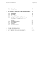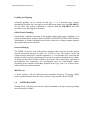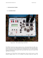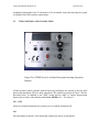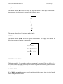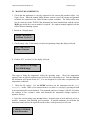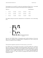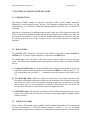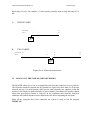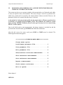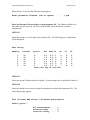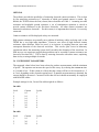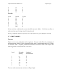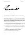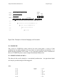
1
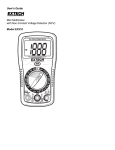
CAMPUS IN TERNATIONAL
PRODUCTS LTD
GEOPULSE TIGRE RESISTIVITY METER
USER’S MANUAL
CAMPUS INTERNATIONAL PRODUCTS LTD
CONCEPT HOUSE
8, THE TOWNSEND CENTRE
BLACKBURN ROAD
DUNSTABLE.
BEDFORDSHIRE
ENGLAND
LU5 5BQ
TEL: (44) 1 582 606 999
Campus International Products Ltd.
Geopulse Tigre
FAX: (44) 1 582 606 991
WARRANTY
1.
Campus International Products Ltd products are fully tested in our workshop both during construction
and after completion and are dispatched in full working condition. Instruments are guaranteed for 12
months from the date of dispatch from the factory, liability being limited in accordance with clause 9 of
the General Conditions for the Supply of Plant and Machinery for Export (UN Economic Commission
for Europe, Geneva, 1953).
2.
When unpacking, please check the contents against the packing list and inspect for damage and
malfunction of any kind. In the case of any defect, inform the carrier immediately and report in full to
Campus or their local agent the extent of the damage. Await their reply before taking any further action,
except in exceptional circumstances.
3.
Should a fault be identified that cannot be remedied on site within the guaranteed period, consult with
Campus. Normal procedure will be to return the unit (or complete system if necessary), carriage paid, to
Campus for inspection and repair or replacement free of charge, provided the fault has not been due to
misuse.
4.
As far as possible use original case and packaging material for return of the instrument. Equipment is on
occasions subject to very rough handling during transit and Campus cannot be liable for damage due to
faulty packing.
5.
It is the responsibility of the customer to notify Campus or their agent of defect or damage to the
equipment within a reasonable time of receipt. We would recommend that any defect or omission should
be notified verbally but with written confirmation no more than 72 hours after receipt of the product.
6.
Campus International Products Ltd will take all necessary steps to rectify any failure, which is deemed
the responsibility of the manufacturer, as quickly as possible.
7.
No liability against consequential loss can be excepted under any conditions.
Thank you for purchasing the Geopulse Tigre Resistivity Meter.
Campus International Products Ltd. Service and Sales Centre
Campus International Products Ltd.
Concept House
8, The Townsend Centre
Blackburn Road
Dunstable
Bedfordshire
England
Tel: +44 (0) 1582 606 999
Fax: +44 (0) 1582 606 991
Attn: Matthew Stares
Attn: David Smale
Attn: Norman Bell
(Technical enquiries)
(Geophysical enquiries)
(Sales enquiries)
Campus International Products Ltd.
Geopulse Tigre
Campus International Products Ltd.
Copyright © 1999 Campus International Products Ltd.
All rights reserved including the right of reproduction
in whole or in part in any form.
Published by Campus International Products Ltd.
Concept House
8, The Townsend Centre
Balckburn Road
Dunstable.
Bedfordshire
England
LU5 5BQ
Printed in Great Britain
Campus, Geopulse and Tigre are registered trademarks of Campus International Products Ltd.
Geopulse Tigre
Campus International Products Ltd.
Geopulse Tigre
INTRODUCTION
THE CAMPUS TIGRE RESISTIVITY METER
The CAMPUS TIGRE is a high quality earth resistance meter capable of accurate
measurements over a wide range of conditions. To enhance its capabilities it is provided with
an optional computer link enabling control to be transferred to a PC notebook computer. The
TIGRE can also incorporate banks of relays, which will allow computer-controlled sounding
and imaging.
Campus International Products Ltd.
Geopulse Tigre
CONTENTS
WARRANTY
2
INTRODUCTION
4
CONTENTS
5-6
1.
GENERAL DESCRIPTION OF THE
TIGRE RESISTIVITY SYSTEM
1.1
1.2
1.3
1.4
2.
The TIGRE
Computer Control
The Survey Systems
1.3.1 Profile and Mapping
1.3.2 Offset Wenner Sounding
1.3.3 Electrical Imaging
1.3.4 MRT Surveys
Power Booster
THE TIGRE INSTRUMENT
2.1
2.2
2.3
2.4
2.5
7
7
7
7
8
8
8
8
8
9
Construction
The Controls and Connections
9
10
2.2.1 ON – Off Switch
2.2.2 Go button
2.2.3 mA (current) button
2.2.4 MODE button
2.2.5 Number of Cycles
2.2.6 Sample Time
2.2.7 Alpha-Numeric Display
2.2.8 External Power Supply
2.2.9 Computer Control
2.2.10 Manual Control
2.2.11 External System Connection
10
10
11
11
11
11
12
12
13
13
13
Making Measurements
The Signal
Power Supply
14
16
17
Campus International Products Ltd.
2.6
3.
Battery Charger
Geopulse Tigre
17
ELECTRICAL IMAGING WITH IMAGER CABLES
18
3.1
3.2
3.3
3.4
3.5
18
18
18
19
3.6
3.7
3.8
3.9
Introduction
The system
Choice of Cable
Laying Out the Cables and Electrodes
Designing and Carrying Out a Survey with
TIGREPRM and TIGRECOM Control
Software
Instrument Parameters
Survey Modes
Problems
Presentation of Data
20
23
24
26
26
4.
TIGRE SPECIFICATIONS
27
5.
EC CERTIFICATES OF CONFORMITY
28 - 29
Campus International Products Ltd.
Geopulse Tigre
1. GENERAL DESCRIPTION OF THE SYSTEM
1.1.
THE TIGRE
The TIGRE is a high quality earth resistance meter capable of accurate measurement over
a wide range of conditions.
It has a maximum power output of 18 watts, manual selection of current in steps up to
100mA, a choice of sample time / signal length averaged and three frequency settings. The
receiver incorporates automatic gain steps, which provide a range of measurements from
0.00001Ω το 2000kΩ.
The instrument is powered by a large capacity rechargeable battery providing several days
of use without recharging in average terrain conditions. The TIGRE is housed in an
impact-0resistant steel case.
1.2.
COMPUTER CONTROL
Though the TIGRE can be used as a stand-alone system to carry out electrical profiling or
vertical soundings with any type of electrode array, it has been designed with a view to
integrating it with a number of resistivity survey systems developed by Campus
International Products. To make this possible, control of the instrument is transferred to a
portable notebook computer (IBM compatible). The computer automatically switches in
the correct electrodes for each particular measurement through a bank of relays housed in
the meter.
Computer control also has the advantage of making possible a much wider range of
instrument parameters than would otherwise be practicable. The square wave reversal
periodicity and the current-on to current-off ratio can both be modified in order to optimise
measurement quality. All data are logged and are immediately available for interpretation.
Self-potential readings can also be monitored and there are a number of check routines.
Basic software for operating the computer is provided on a 3.5" floppy disc supplied with
the manual.
1.3.
THE SURVEY SYSTEM
The construction of the TIGRE, with its own switching capabilities makes it easy to
operate with a variety of survey systems. These can only be operated when the instrument
is functioning under computer control.
Campus International Products Ltd.
Geopulse Tigre
Profiling and Mapping
Automatic profiling can be carried out with any 2, 3 or 4 electrode array. Campus
International Products Ltd. can supply a special half-meter square array (the SQUARE-4),
for use where only shallow penetration is required. With the SQUARE-4 and other
electrode arrays, data logging is automatic.
Offset Wenner Sounding
Electronically controlled switching in the module enables high quality soundings to be
measured automatically using the patent OFFSET SOUNDING SYSTEM. Offset Wenner,
Schlumberger or Wenner soundings may be easily carried out. A laptop computer operates
the program and processes the data.
Electrical Imaging
The TIGRE can also be used with multicore imaging cables with any electrode spacing
Normal operational spacings are either 1m, 2,m 5m or 10m. The software carries out
repeated sweeps along with a constant separation 2-,3- or 4-electrode array, increasing the
spacing at each sweep, thus producing an electrical cross section (pseudosection) or image
of the ground that can be further refined by processing. This is particularly applicable to
environmental and engineering site investigations and for archaeological studies.
Depending on the amount of switching included in the Tigre, from 1 to 8 cables can be
connected directly to the instrument.
MRT Surveys
A direct interface with the Microprocessor-controlled Resistivity Traversing (MRT)
system (a patented smart electrode survey system) is also possible with the TIGRE.
1.4.
POWER BOOSTER
Starting in July 1999 the power booster is fitted as standard to all Tigre systems providing
current capacity to 200mA.
Campus International Products Ltd.
Geopulse Tigre
2. THE GEOPULSE TIGRE
2.1 CONSTRUCTION
Figure One – The Geopulse Tigre Front Panel
The TIGRE is housed in an impact-resistant steel case with removable lid and is fully waterresistant. The various units are mounted below the front panel and the whole instrument can be
removed from the case by unscrewing the plate. The transmitter/receiver controls and display
occupy the left hand half of the panel, while client-selected cable sockets are located on the
right hand half of the panel.
The design of the TIGRE allows for the construction of a basic resistivity meter or a multi
electrode imaging system, up to 256 electrodes. The design concept also allows for
Campus International Products Ltd.
Geopulse Tigre
straightforward upgrade from 32 electrodes to 256, in modular steps, thus allowing the system
to expand in line with customer requirements.
2.2
THE CONTROLS AND CONNECTORS
Figure Two TIGRE Lower Left-Hand front panel showing Operation
Buttons
All the external controls, together with the liquid crystal display are situated on the top front
panel of the instrument. They are fully waterproof. The controls are shown in Figure 2 and are
described below. In addition to the “ON” switch and the “GO” or initiate measurement
button, there are three other buttons marked mA, MODE and ~ See Figure 3.
ON – OFF
Select to switch the instrument for operation or to switch the instrument off.
GO
Press this button to initiate / Start measuring with the previously set parameters.
Campus International Products Ltd.
Geopulse Tigre
mA (Current)
The button marked mA is used to select the desired current in milli-amps. The current is
increased each time the button is pressed in the following steps:
0.5
1
2
5
10
20
50
100
The current value selected is indicated on the display.
MODE
The button marked MODE selects the type of measurement. The display will indicate the
following sequence of options as appropriate.
Resistance
Self potential
Battery Volts
NUMBER OF CYCLES
~
The button marked
selects the number of readings to be averaged. This can be from 1 to
16. Details of how the signal is processed to obtain a single measurement of ground resistance
are given in Section 2.4. of this manual.
SAMPLE TIME
If the MODE and mA buttons are pressed simultaneously the sample time (or signal length)
can be changed as shown below:
Campus International Products Ltd.
Geopulse Tigre
0.8s
1.2s
2.4s
APLHA-NUMERIC DISPLAY
The 80-character (4x20) liquid crystal display indicates the parameters selected and the
measurement details as the survey progresses. See Figure Three. The display can be backlit by
pressing MODE and ~ simultaneously. The light automatically switches of after one minute if
no activity is sensed during this time.
Figure Three TIGRE Display and Electrode Terminals
EXTERNAL POWER SUPPLY
An external 12V-power supply may be connected through the socket situated immediately
below the RS232 socket. See Figure Five. A connecting lead is supplied for this purpose. It is
important to remember the correct polarity when connecting to an external supply.
WARNING: DO NOT CONNECT TO A CAR BATTERY WHILE IT IS
BEING CHARGED!
Campus International Products Ltd.
Geopulse Tigre
COMPUTER CONTROL
To operate under computer control, connect any IBM compatible notebook computer to the
resistivity meter via the RS232 port. See Figure Five. A connecting lead is supplied. The
correct connections to the instrument are shown below (Figure Four).
4
1
3
2
Ground
1
Rx
Tx
Figure Four RS232-port connections
MANUAL CONTROL
The red and black coloured current and potential terminals marked P1, P2, C1, C2, are
situated on the front panel – See Figure Three. Single core cables may be connected to these
terminals for measuring earth resistance.
EXTERNAL SYSTEM CONNECTION
The connector marked MOD allows connection of the Campus Square-4 or other profilling
systems. See Figure Five.
Figure Five TIGRE Display and Electrode Terminals
Campus International Products Ltd.
Geopulse Tigre
2.3 MAKING MEASUREMENTS
1. Check that the instrument is correctly connected to the current and potential cables. See
Figure Seven. When the manual Offset Wenner system is used, the current and potential
terminals are connected to the Offset Wenner system switchbox. The Offset cables may
also be connected to the TIGRE if the instrument has been manufactured with the correct
MOD port and in this case no module is required. See separate manual supplied with the
Offset Wenner Sounding System.
2. Switch on. Display shows
MODE: Resistance
1=0.5mA Cycles=2
3. Check battery volts. If the battery is below the operating voltage the display will read
BATTERY LOW
Reduce Current
4. If above 50°C or below 0°C the display will read
INT TEMP OVER 50degC
Or UNDER 0degC
Take steps to bring the temperature within the operating range. Check the temperature
regularly since in tropical sunshine it may well rise above the danger level. Note that although
the instrument will operate below 0°C, it is not designed for work under exceptionally low
temperature conditions.
5. Check the SP voltage. Use the MODE switch to put the instrument into the Self
Potential mode. Make a few measurements to see how it is varying by pressing the GO
switch and noting the results obtained. The amplitude and rate of change of the SP will affect
the readings at low resistance values and determine the instrument settings required to
optimise accuracy.
6. Select the current setting using the mA button. Normally start at 2mA and keep as low as
possible, consistent with obtaining good repetition. If ground conditions are such that the
instrument cannot deliver the required current or there is an open circuit it will read
CURRENT ERROR
Check Electrodes
Campus International Products Ltd.
Geopulse Tigre
Decrease the current and/or water the electrodes to improve ground contact.
Experience shows that when operating multicore cable systems, accurate measurements are
obtained with contact resistances below 2000Ω.
~
7. Select the number of readings to be averaged using the
button. This will depend to a
great extent on ground noise. Start with 4 readings and increase or decrease depending on the
consistency of the readings obtained.
8. Select Resistance and press the GO button. The display will initially indicate the
voltage gain being used in the measurement.
…Setting Gain
G=5 I=2mA n-3
indicates the amplifier gain setting. These are x5, x0.5, x0.05 and x0.005. In a noisy
environment, high and varying SP values may cause the amplifier to saturate during the
averaging. The display will show
GAIN ERROR
Change Current
In this case, reduce the current to bring the signal within the operating range.
The display will then indicate the successive averages of the resistance, bleeping each time
during the process. At the standard setting the instrument takes 2.1s to complete a set of 4
readings. A three-figure resistance will show with the decimal point approximately placed,
followed by Ω or mΩ. If the potential and current connections have been incorrectly
connected a negative sign will precede the digits. This can also be due to ground conditions.
9. If the switching circuits operated by the current or mode buttons on the top panel are faulty
the display will read MODE ERROR.
2.4 THE SIGNAL
Campus International Products Ltd.
Geopulse Tigre
The transmitter uses reversed DC to produce the signal shown in Figure Six (a). An internal
three-position switch on the microprocessor board provides three sampling rates.
These are: -
Repetition time
1.
1.0s on
0.4s off,
1.0s on,
0.4s off.
2.8sec.
2.
1.5s on
0.6s off
1.5s on
0.6s off
4.2sec.
3.
3.0s on
1.2s off
3.0s on
1.2s off
8.4sec.
The standard setting with which the instrument leaves our laboratories is the second setting
above.
mA
(a)
Volts
(b)
A
B
C
Seconds
Figure Six. The TIGRE SIGNAL (a) Transmitted signal (variable Periodicity), (b) Received
signal. Here the attenuated and modified signal is superimposed on slowly varying earth
currents. It is sampled over times A, B and C.
The on period is sampled for only the last 4/5 of the on time e.g. 0.6s in 0.75s.
An example of the received signal in the presence of electrical ground noise is shown in
Figure 3b. This figure also illustrates the processing technique used to extract a value of the
required potential difference from the received signal, here shown superimposed on a slowly
varying earth current. The signal is digitally sampled over times A, B and C and the amplitude
calculated as (Va+Vc–2Vb)/4). The on/off ratio is 2.5:1 and the sample/unsampled ratio
during any on period is 4:1. This is to allow any coupling and IP affects to die away before
sampling takes place.
Campus International Products Ltd.
Geopulse Tigre
When a number of cycles are averaged the microprocessor calculates the potential difference
from successive sets of three “on” periods, ABC, BCD, CDE, giving values (Va+Vc–2Vb)/4,
(Vb+Vd–2Vc)/4, etc.
When conditions are adverse, e.g. a low signal/ground noise ratio, apparent as a lack of
consistency in the readings, use higher current settings that do not cause a “GAIN ERROR”
and average over 16 cycles. Gain errors are usually due to sudden increases in ground noise
saturating the system. If the area is generally very noisy it may be necessary to operate at the
longest cycling time. In extreme conditions, i.e. measuring very low resistances against a
background of large amplitude and varying SP, highly inconsistent readings may be obtained.
In this case it is necessary to put the instrument into the computer command mode and vary
the sampling parameters until satisfactory results are obtained. See Section 3.
2.5 POWER SUPPLY
The Tigre uses sealed lead-acid batteries (7 Amph at 12v). Under average working conditions
(e.g. 10 offset soundings per day at 5mA) recharging every 2 working days would be safe
practice. Electrical imaging uses more drain on the batteries and so the instrument should be
charged overnight during survey operations.
Should it be necessary to be away from a mains power source for more than a few days the
instrument can be operated using an external supply. A 12V-car battery which can recharged
from a vehicle can be used in an emergency. A separate lead and plug is supplied which is
plugged into the battery charger socket and the lead connected to the battery. Be sure to check
the polarity before connecting to the instrument.
WARNING: Do not run the vehicle engine while the instrument is connected to
the battery as transients from the alternator can damage the transmitter
circuitry.
2.6
BATTERY CHARGER
This operates from 240v or 115vac. The maximum current output is such that batteries can be
left on indefinitely without suffering and damage. Charging time from full discharge is 16
hours.
NOTE:
IF THE METER IS OPERATED WHILE THE BATTERY IS BEING
CHARGED, THE CHARGER IS AUTOMATICALLY DISCONNECTED.
Campus International Products Ltd.
Geopulse Tigre
3 ELECTRICAL IMAGING WITH THE TIGRE
3.1 INTRODUCTION
The campus TIGRE contains an optional switching module, which enables automatic
addressing of multi-electrode survey systems. The minimum configuration allows for the
switching of up to 32 electrodes. Additional onboard modules will allow for 64, 128 and 256
electrodes.
Each survey electrode may be addressed and set up as either one of the current electrodes C1
or C2, or one of the potential electrodes, P1 or P2. An electrode may be addressed to take two
roles so that, for example, it can act as both C1 and P1. Additionally far electrodes may also
be connected directly to the Tigre resistance meter. The system therefore has complete
versatility.
3.2 THE SYSTEM
The IMAGER cables should be connected to the TIGRE at the sockets marked CABLE 1,
CABLE 2 etc. A portable Laptop computer is connected to the RS232 port.
The relationships of the electrodes to the relays in the control module are shown in Figure
Seven. The following description assumes that standard 32-takeout cables are employed in the
surveys.
A. A single IMAGER cable. If a single IMAGER cable is being used it should be connected
to the left connector on the front panel, socket marked CABLE 1. In this case relays 1 – 32
will correspond to the electrodes 1 – 32 numbered from the connector (See Figure Seven
A).
B. Two IMAGER cables. When two cables are connected to the control instrument, the
electrodes will normally be numbered from one end of the line of 64 electrodes to the other
end. In this case relay 32 will correspond to electrode 1 and relay 1 to electrode 32. On the
second cable, relay 33 will correspond to electrode 33 and so on to relay 64 which will
correspond to electrode 64. Full details are shown in Figure Seven B.
C. X IMAGER cables. The versatile construction of the TIGRE presently allows for up to 8
cables to be connected or 256 electrodes. The above configuration applies regardless of the
number of cables.
3.3
CHOICE OF CABLE
Select a cable with electrode spacing suitable for the problem being studied. If measurements
are made with multiples, n, of the unit electrode spacing, a, from n = 1 to n = 8, the depth
range covered is approximately from a/3 to 6a although the greatest response will be from the
Campus International Products Ltd.
Geopulse Tigre
depth range a/2 to 4a. For example, a 1 meter spacing would be used to study the range 0.5 to
4m.
A.
SINGLE CABLE
ELECTRODE
1
32
RELAY
1
32
Tigre
B.
TWO CABLES
ELECTRODE
32
1
33
64
RELAY
1
32
33
64
Tigre
Figure Seven Electrode connections.
3.4
LAYING OUT THE CABLES AND ELECTRODES
The IMAGER cables are set out in a straight line and electrodes connected to every takeout.
The electrodes should be inserted into the ground to a depth of no more than 5% of the unit
electrode spacing. For small spacing cables special small electrodes are supplied so that the
operator is not tempted to plant electrodes to greater depths. Nevertheless the operator should
ensure that good ground contact is achieved. In dry conditions each electrode should be
withdrawn and a small amount of water added to the hole before replanting the electrode.
When all the electrodes have been connected, the system is ready to run the program
TIGRECON.
Campus International Products Ltd.
3.5
Geopulse Tigre
DESIGNING AND CARRYING OUT A SURVEY WITH TIGREPRM AND
TIGRECON CONTROL SOFTWARE.
The system may be set up to operate routinely with any particular set of electrodes and cables
to carry out specific survey measurements. The survey design is stored in a parameter file,
which once created can be accessed by the control software whenever needed. However, the
parameter file has to be created when the survey is first run.
A fast method of setting up parameter files for the measurement of Wenner pseudosections
is included as a separate program PRM64_2.EXE. The parameter file should be created
before running TIGIMG. Parameter files for other types of survey are best created using
EXCEL or other software.
Once in the field ready to start measurements, the laptop computer is switched on and the
system booted. Insert the disk, type TIGIMG and follow the instructions.
After the title screen, the correct serial port (COM1 or COM2) must be selected. The
following main menu then appears.
**************TIGRECON MAIN MENU************
Please enter option
Load/Create parameter file.................1
View parameter file........................2
Edit parameter file........................3
Take/continue resistance measurement.......4
Show resistance measurements...............5
Save resistance measurements...............6
Repeat a measurement.......................7
Check contact resistance...................8
Exit to system.............................9
Select Option 1
OPTION 1
Campus International Products Ltd.
Geopulse Tigre
When Option 1 is selected the following menu appears.
Enter parameter filename (use no spaces)
-
*.prm
Enter the filename of the previously created parameter file. The filename should be no
more than 8 characters long. The file extension .PRM is provided by the computer
automatically.
OPTION 2
Select this option to view the data in the parameter file. The following type of information
will be displayed.
Test Survey
Reading
1
2
3
4
5
6
Current
10
10
10
10
10
10
Cycles
Ton
Toff P1
P2
C1
C2
2
1.0
0.5 1
2
2
1.0
0.5 2
3
2
1.0
0.5 3
4
2
1.0
0.5 4
5
2
1.0
0.5 5
6
2
1.0
0.5 6
7
Press any key to continue
3
4
5
6
7
8
4
5
6
7
8
9
OPTION 3
Select this option if further editing is required. Screen messages are as described in Option 1.
OPTION 4
Select this option to start a survey using the parameters described in the parameter file. The
following message appears.
File filename.PRM allows 6 different measurements
Select option:All measurements.......1
Selected range.........2
Continue survey........3
Campus International Products Ltd.
Geopulse Tigre
If only a selected range is required the program will ask for:
Number of first measurement?
Number of last measurement?
Sub-option 3 above can be used after a set of resistance measurements has been interrupted
(where the user has had to return to the main menu to edit a parameter file for example).
The computer then prints a message instructing the operator to
SWITCH
SWITCH
SWITCH
SWITCH
SWITCH
SWITCH
ON
ON
ON
ON
ON
ON
METER
METER
METER
METER
METER
METER
The computer then completes a set of resistance measurements displaying the results as they
are obtained.
OPTION 5
The resistances may be examined using this option. If it is necessary to repeat a measurement,
the operator should proceed to Option 7.
OPTION 6
Select this option to store data on disk. A filename for data storage has to be supplied.
OPTION 7
To repeat a measurement, the number of the measurement as it appears in the parameter file
has to be entered.
Campus International Products Ltd.
Geopulse Tigre
OPTION 8
The software provides the possibility of estimating electrode contact resistances. This is done
by first measuring resistances at 3 electrodes at which good ground contact is certain. By
default, the TIGRE selects the first (closest) three electrodes on Cable 1. Assuming no cable
resistance and negligible ground resistance, a set of simultaneous equations is solved to
provide contact resistances at the first three electrodes. All other contact resistances are
measured in relation to electrode 1. For this reason, it is important that electrode 1 is correctly
connected.
Contact resistances will be displayed as they are measured.
High contact resistances are generally not a problem if multicore cables are being used, as the
TIGRE has a very high input impedance. However, one effect of high electrode contact
resistance when multicore cables are used, is an increase in coupling between cores and
consequent distortion of the observed waveform. This can be quite severe in laboratory
experiments where the measuring system itself can add to the distortion of the waveform. In
field surveys our experience suggests that good data can be recorded if contact resistances are
lowered to less than 200Ω. This is done by watering electrodes with saline water, emplacing
them in clay or using multiple electrodes.
3.6 INSTRUMENT PARAMETERS
The suggested values below have been selected to produce measurements with the minimum
of power. The operator can increase the speed of the survey by reducing the current on time
to 1 second or less. If this is done it is likely that the current will have to be increased to 1, 2
or 5 mA, depending on the electrode spacing used. If unstable measurements are obtained, the
current should be increased. Currents of more than 100 mA should not normally be employed
with IMAGER cables.
Example settings for 1m, 2m and 5m cables might be as follows:
1m cable
Level
1
2
3
4
5
6
7
Current
0.5
1.0
1.0
1.0
1.0
2.0
2.0
Cycles
3
3
3
4
4
4
4
Current
1.0
2.0
2.0
Cycles
3
3
4
2m cable
Level
1
2
3
Campus International Products Ltd.
Geopulse Tigre
4
5
6
7
5m cable
2.0
2.0
5.0
5.0
4
4
4
4
Level
1
2
3
4
5
6
7
Current
2.0
5.0
5.0
5.0
5.0
10.0
10.0
Cycles
4
4
4
4
4
4
4
In low resistivity conditions the current should be increased further. Check the waveform to
make sure that a good voltage signal is being detected.
In noisy conditions either the current on time or the number of cycles should be increased.
3.7 SURVEY MODES
Traverse
There are two survey modes that can be employed. Traverse mode allows the completion of
all measurements with n=1 before commencing with the n=2 measurements and so on. With a
25 electrode cable a complete pseudosection measured in traverse mode will comprise the
following number of measurements at each level.
Level
Electrode
Spacing
Number of
measurements
1
2
3
4
5
6
7
a
2a
3a
4a
5a
6a
7a
22
19
16
13
10
7
4
Traverse mode measurements are shown in Figure Eight.
Campus International Products Ltd.
Station 4
Geopulse Tigre
C1 P1 P2 C2
Resistance
meter with
Control
module
Station 3 C 1 P 1 P 2 C 2
Laptop
computer
Station 2 C 1 P 1 P 2 C 2
Station 1
25 electrodes
C1 P1 P2 C2
a
n=1
n=2
n=3
n=4
n=5
a
a
l
1
l
2
l
3
l
l
4
l
l
l
l
l
l
l
l
l
l
l
l
l
l
l
l
l
l
l
l
l
l
l
l
l
l
l
l
l
l
l
l
l
l
l
l
l
l
l
1
l
l
l
l
l
l
l
l
l
l
l
l
Figure Eight Principle of electrical imaging with a multicore cable in traverse mode
Roll-on
Roll-on mode takes measurements for n=1, 2, 3, 4, 5 and 6 for station 1 before continuing in
the same way for station 2 (Figure Nine). This type of survey should be used if the survey line
is likely to extend to more than 25 electrodes. The operator can stipulate the number of
measurements which are made before the cable is moved and the process repeated. There are
many ways such a survey can be carried out but the following technique will provide
continuous cover at Level 7 quickly and efficiently.
1. The cable is set out and measurements are made in Roll-on mode for 7 stations. The table
above shows that this is the maximum number of measurements possible at Level 6 with
25 electrodes deployed. Be sure to record the data before progressing .
2. The cable is disconnected and moved along the line until takeout 1 arrives at electrode 8.
The 7 used electrodes are moved to the forward end of the line so that 25 electrodes are
again connected.
3. The TIGRECON survey program is continued in Roll-on mode for a further 7 stations.
The measured data are appended to the end of the data file created in step 1.
4. The process is repeated until the final cable position is reached.
5. At the end of each roll-on stage a message is displayed.
Campus International Products Ltd.
Station 3
C1
P1
P2
C1
Station 1
C1 P1 P2 C2
a
n=1
n=2
P2
P1
Station 2
a
a
l
1
l
Laptop
computer
C2
l
l
l
l
l
3
n=3
Resistance
meter with
Control
module
C2
25 electrodes
l
l
2
Geopulse Tigre
l
l
l
l
l
l
l
l
l
l
l
l
l
l
l
l
l
l
l
l
l
l
l
l
l
l
l
l
l
l
l
l
l
l
l
1
l
4
n=4
l
l
l
5
n=5
l
l
l
l
l
l
l
l
Figure Nine Principle of electrical imaging in roll-on mode.
3.8 PROBLEMS
This version of TIGRECON control software has been tested under a variety of field
conditions but inevitably problems will occur when it is used in different environments. It is
hoped that these problems will be minor. If you experience problems or have comments on
the use of TIGRECON please contact Campus International Products Ltd..
3.9 PRESENTATION OF DATA
The observed data can be plotted as a conventional pseudosection. An approximate depth
scale may be provided using the following guide.
when
n=1
n=2
n=3
n=4
n=5
n=6
depth
=a/2
=a
= 3a / 2
= 2a
= 5a / 2
= 3a
Campus International Products Ltd.
Geopulse Tigre
The pseudosection can be contoured and viewed as an approximate image of the subsurface.
An automatic inversion program – RES2DINV – is available and enables coloured images of
the ground to be produced automatically. Alternatively it can be modelled using a forward
modelling program such as RESIXIP2D also available from Campus.
4
TIGRE SPECIFICATIONS
TRANSMITTER
Maximum power output:
Current range :
Square wave repetition:
Number of readings averaged:
18W
0.5mA to 100mA
8.4s, 4.2s. 2.8s.
1 to 16.
RECEIVER
Input voltage range:
Input impedance:
0 –180V with auto gain averaging.
22MΩ.
Measurement range:
Low pass filter
360KΩ – 0.001Ω.
Display:
Power supply:
80 character alphanumeric liquid crystal
Rechargeable sealed lead acid.
7 Amp/h @ 12v
GENERAL
Weight:
Electrode capacity
6kg
32 to 256 (optional)
Link to portable IBM compatible PC provides:1.
2.
3.
4.
Wide choice of waveform and frequency
Choice of sampling interval
Display of received waveform
Data logging
Campus International Products Ltd.
Geopulse Tigre
CERTIFICATE OF CONFORMITY
Product:
charger for GEOPULSE TIGRE earth resistance meter
Serial No.
SN0010
Date of Shipment:
JULY 2000
EMC 89/336/EEC Generic EN50081/1 Light Industrial Emissions,
EN50082/1 Light Industrial Immunity
Tests Applied
BSEN 55011 Class B Conducted Emissions
BSEN 55011 Class B Radiated Emissions
BSEN 61000-4-4 Fast Burst Transients to Level 2 Light Industrial
BSEN 61000-4-2 Static Discharge to Level 2 Light Industrial
Category 1 PASS
Low Voltage Directive 73/23/EEC: N/A below 50V AC.
Machinery Directive 98/37/EEC: N/A – no moving parts.
We, on behalf of Campus International Products Ltd., confirm the Product described
above meets the requirement in all respects.
Signed……………………….. Authorised Signatory………………………..
Campus International Products Ltd.
Concept House
Blackburn Road
Dunstable
Bedfordshire
England
LU5 5BQ
Tel: +44 (0) 1582 606 999
Fax: +44 (0) 1582 606 991
Campus International Products Ltd.
Geopulse Tigre
CERTIFICATE OF CONFORMITY
Product:
GEOPULSE TIGRE earth resistance meter
Serial No.
SN0010
Date of Shipment:
JULY 2000
EMC 89/336/EEC Generic EN50081/1 Light Industrial Emissions,
EN50082/1 Light Industrial Immunity
Tests Applied
BSEN 55011 Class B Radiated Emissions
BSEN 61000-4-4 Fast Burst Transients to Level 2 Light Industrial
BSEN 61000-4-2 Static Discharge to Level 2 Light Industrial
Category 3 PASS
BSEN 55011 Class B Conducted Emissions: N/A – battery only
Low Voltage Directive 73/23/EEC: N/A below 50V AC.
Machinery Directive 98/37/EEC: N/A – no moving parts.
We, on behalf of Campus International Products Ltd., confirm the Product described
above meets the requirement in all respects.
Signed……………………….. Authorised Signatory………………………..
Campus International Products Ltd.
Geopulse Tigre
Campus International Products Ltd.
USER MANUAL COMMENTS SHEET
Please note on a copy of this form any suggestions for improvement or any errors
found in this manual. Please return the form to:-
David Smale
Campus International Products Ltd.
Concept House
Blackburn Road
Dunstable
Bedfordshire
LU5 5BQ
ENGLAND
Manual Title
Rev Number
Comments