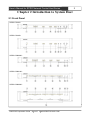
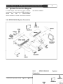
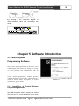
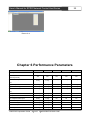
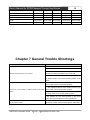
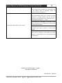
1
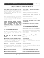
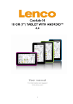
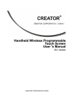
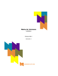
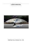
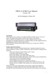
CREATOR CORPORATION(CHINA)
User ’s Manual for
SPRO Network Control
Host Series
V1.0
CREATOR Corporation China
Meaning of the symbols
■ Safety Instruction
Symbols are used in the Manual and devices, referring to the possible risk to users or others , as well as the
damage to property, for helping you to safely and properly use the devices. The instruction and the implications
are as follows. Please make sure your correct understanding of these instructions before using the Manual.
Warning
Caution
To remind user to conduct according to the attached
operation and maintenance instructions. If ignore
these information, death or injury could possibly
happen.
To remind the user that the risky uninsulated voltage
in the device could caused electric shock to human.
Caution: To avoid electric shock, please don't open
the case, nor put the useless parts in it. Please
contact with qualified service staff.
CE authentication indicates the product is in line
with the EU safety regulation, and for assurance of
safety use.
SGS Authentication indicates the product has
reached the QC standard of the global-biggest Swiss
universe surveyor.
This product has acquired the ISO9001 International
Quality Authentication (Authentication authority:
Germany Rheinland TUV)
■
General Information Instruction
List the situation of causing unsuccessful operation
or setup, and relevant information needed to notice.
Lead to the page with detailed information on
relevant topic.
Important Notices
Caution
To ensure the device in reliable use and personal
safety, please abide by the following items when in
installation, use and maintenance:
Notice in installation
◆ Please DO NOT use the product in following
places: the places with dust, oily smoke, electrical
conductive dust, corrosive gas, inflammable gas; the
places with high temperature, due, rain and wind
exposures; the places endangered by shock and
vibration. Electric shock, fire and incorrect operation
could also cause damage and deterioration to the
product.
◆
When conducting screw drilling and wiring
process, DO NOT let metal irons and wire lead drop
into the controller and air vent, which could possibly
cause fire, failure and accidental operation.
◆ After finishing the installation, it is necessary to
ensure there is no foreign matter including the
packing material like contact paper on the ventilation
surface, otherwise, it could cause poor heat
dissipation while running, as well as fire, failure and
accidental operation.
◆ Avoid conducting wiring and plugging in/out
cable socket with electricity, otherwise, electric shock,
circuit damage could easily happen.
◆ Installation and wiring should be firm and reliable.
Poor contact could cause malfunction.
◆ With regard to the application situations with
strong interference, shielded cable should be used for
the input and output of HF signal, to improve the
anti-interference performance of the system.
Note in Wiring
◆ Installation and wiring shouldn't be conducted
until external electric power is cut off, otherwise,
electric shock or device damage could happen.
◆ The product is grounded by the earth lead of the
power cable. To avoid electric shock, the earth lead is
necessary to be connected with the ground. Before
making connection with the output end or input end
of the product, please ensure it is correctly grounding.
◆ Upon finish wiring, remove the sundries. Please
cover up the terminal plate for avoiding electric
shock.
Note for Operation and Maintenance
◆ Please DO NOT touch the terminal when with
electricity, otherwise, electric shock could happen.
◆
Don't clean up and screw the terminal tight
before power is off. Such operation could cause
electric shock when with electricity.
◆ Please turn off the power before connecting or
disconnecting the communication signal cable,
peripheral modules or control units, otherwise, device
could be damaged and accidental operation could
happen.
◆ Please DO NOT disassemble the device, so as to
avoid internal electric components damage.
◆ It is necessary to read through the Manual and
fully ensure the safety, before altering the program,
trial running, starting and stopping operation.
◆ Button battery shouldn't be replaced before the
power is off. If it has to be replaced when the device
is running, it should be conducted by professional
electric technician wearing insulated gloves.
Note for declaration of the worthless.
When declaring of worthless, please note
◆ Explosion of electrolytic capacitor on the circuit
board could happen when burning it.
◆ Please classify and dispose it. Don't dispose it into
household garbage.
◆ Please deal it as industrial waste, or in accordance
with local environmental protection regulation.
Forward
User’s Manual for SPRO Network Control Host Series mainly introduces the operation manner, primary
parameters and trouble shootings of SPRO-CAV801 、 SPRO-CAV802 、 SPRO-CON9000 、
SPRO-CON9100、and SPRO-CON9200 network control hosts
The Manual serves as user's operation instruction only, rather than for maintenance service purpose. Since the
date of release, any function or relevant parameter alteration will be provided in supplement instruction. Please
refer to the manufacturer or dealers for inquiry.
CREATOR Electronics own the copyright of the Manual. Without permission, any unit or person shall not take
part or total of the Manual for business purpose.
The copyright of the Manual is protected by Copyright Law of People’s Republic of China and other Intellectual
Property Law. Without written permission, any copy or distribution is prohibited.
Index
Chapter 1 General Introduction.............................................................................................................................1
1.1
Functions and Features.......................................................................................................................... 1
1.2
Components of the Product................................................................................................................... 1
1.3
Accessory and Compatiable Products................................................................................................. 1
1.4
Device Installation....................................................................................................................................2
Chapter 2 Introduction to the Host........................................................................................................................3
2.1
Front Panel................................................................................................................................................3
2.2
Rear Panel................................................................................................................................................ 5
2.3
Introduction to Part of Ports in the Host............................................................................................... 7
2.3.1 COM Port Function.................................................................................................................... 7
2.3.2 CR-NET Connection.................................................................................................................. 7
2.3.3 USB Port Connection.................................................................................................................7
2.3.4 Audio Port Connection...............................................................................................................7
2.4
System Connection Diagram................................................................................................................. 8
2.4.1 SPRO-CAV802 System Connection....................................................................................... 8
2.4.2 SPRO-CON9200 System Connection.................................................................................... 9
2.4.3 Connection between SPRO Series Host and Wireless(RF)Touch Screen................. 9
2.4.4 Connection between SPRO Series Host and Wireless(WiFi)Touch Screen............ 10
2.4.5 Connection between SPRO Series Host and Wired(CR-NET)Touch Screen..........10
2.4.6 Connection between SPRO Series Host and Wired Ethernet Touch Screen................ 11
Chapter 3 Receiver............................................................................................................................................... 12
3.1
CR-WF10 Wireless AP (Acess Point)................................................................................................ 12
3.1.1 CR-WF10 Configuration..........................................................................................................12
3.1.2 Connection................................................................................................................................ 15
3.2
Wireless One-way Receiver CR-RFA................................................................................................ 15
3.2.1 Use Guide..................................................................................................................................15
3.3
Wireless Two-way Receiver CR-TRA................................................................................................ 16
3.3.1 Use Guide..................................................................................................................................16
Chapter 4
Introduction to Infrared Transmission Stick ...............................................................................17
4.1
Functions and Features........................................................................................................................17
4.2
Connection..............................................................................................................................................17
Chapter 5 Software Introduction......................................................................................................................... 18
5.1
Control System Programming Software............................................................................................ 18
5.1.1 Installation of Control System Programming Software......................................................18
5.1.2 Monitor Manager Software..................................................................................................... 18
5.1.3 User’s Project Download .......................................................................................................19
5.2
IR Manager- Infrared Code Management Software........................................................................ 20
5.3
Touch Panel- Application of Touch Screen Programming Software............................................. 20
5.3.1 User’s Project Download.........................................................................................................20
Chapter 6 Performance Parameters.................................................................................................................. 22
Chapter 7 General Trouble Shootings............................................................................................................... 23
User’s Manual for SPRO Network Control Host Series
1
Chapter 1 General Introduction
SPRO Network Control Host Series is the new
generation network communication control host
released by CREATOR, adopting 210MHz 32-bit
imbedded processor, ARM7 CPU, 32M memory
and 2M Flash memory.
SPRO Network Control Host Series provides
CR-NET and Ethernet with multiple control ports
including IR (Infrared), I/O (digit input/output),
Relay and COM ports.
Adopting advanced integrated technology,
providing high-speed and accurate centralized
control
environment,
with
open
user’s
programming interface, for completing the
programming of a variety of complicated control
interfaces.
1.1 Functions and Features
◆ Adopting European and US design in smooth
lines, incorporated with fashionable and
innovative idea.
◆
ARM7 CUP , 32M memory , 2M Flash
memory.
◆ Two types of network communication :
CR-NET、Ethernet;
◆ USB2.0 programming communication port
◆ Built-in infrared learner,
fine-tuning and maintenance.
convenient
for
◆ Support local and remote control ways
◆ Universal wide-adaptive
(AC100~240V),
power
design
It is suitable for use in any country and region.
1.2 Components of the Product
SPRO Network Control Host Series includes 5
hosts. They are SPRO-CAV801, SPRO-CAV802,
SPRO-CON9000,
SPRO-CON9100
and
SPRO-CON9200
1.3 Accessory or Compatible
Products
◆ Adopt 210M GHz 32-BIT imbedded processor
◆ 4/8-way independent programmable infrared
transmission port, supporting the control of
multiple same or different infrared devices.
◆ Touch Screen
CR-Wifi G4/G5/G6/G7/G8
4.3、5.7、6.4、7.0、8.4 inch wireless(WIFI)touch
screen
◆3/4/8-way
independent
programmable
RE-232/422/485 control ports. User may program
and configure a variety of control protocols and
codes.
CR-LAN G10/G12/G15
10.2、12.1、15.1 inch wired(Ethernet)two-way
touch screen
◆ 4/8-way light-current relay ports
ST-7600C
7.0 inch wireless (RF) one-way touch screen
◆ 4/8-way digital input/output ports
MT430/LT-5100BW/6500C/7000C/1200C/1300C
CREATOR Corporation China
2010-05
WWW.CREATOR1997.COM
User’s Manual for SPRO Network Control Host Series
4.3、5.7、6.4、12.1 inch wired(CR-NET) two-way
touch screen
DTX-7900C
7.0 inch wireless (TR) two-way touch screen
◆ Remote Controller
CR-Wifi G3
Wireless (WiFi) Two-way Controller
◆ On-wall Panel
CR-WM8/16
8/16 keys on-wall panel connects to the host in
wired (CR-NET) mode.
Other CR-NET BUS Devices
CR-PWR-4/8
4/8-way heavy-current relay
CR-LITE-4A/B 4-way light modulator
CR-VOL
Volume controller
◆ Wireless Transmission Device
CR-WF10
Wireless AP is used along with CREATOR
wireless (WiFi) two-way touch screen.
CR-RFA
Wireless one-way receiver is used along with
CREATOR wireless (RF) one-way touch screen.
CR-TRA
Wireless two-way receiver is used along with
CREATOR wireless (TR) two-way touch screen.
1.4 Devices Installation
SPRO Network Control Host Series can be
installed in a standard 19-inch cabinet, with
accessory of a pair of installation stands. See the
following assembling manner:
CREATOR Corporation China
2010-05
WWW.CREATOR1997.COM
2
User’s Manual for SPRO Network Control Host Series
3
Chapter 2 Introduction to System Host
2.1 Front Panel
SPRO-CAV801:
SPRO-CAV802:
SPRO-CON9000:
SPRO-CON9100:
SPRO-CON9200:
1) POWER—— Power indicator
ACTIVE—— Signal status indicator
2) RS-232/422/485——COM
CREATOR Corporation China
2010-05
WWW.CREATOR1997.COM
data
User’s Manual for SPRO Network Control Host Series
transmission indicator
Supports 3/4/8-way COM port signal
indication (subject to specific model), when data
is being exchanged through COM port,
corresponding indicator will be on. TX is signal
transmission indicator, RX is signal receive
indicator.
3) IR OUT—— Infrared signal indicator
Supports 4/8-way infrared signal indication
(subject to specific model), when the host is
transmitting infrared signal to the device in control,
corresponding indicator will be on.
4) RELAY OUT——Relay
status indicator
power
on/off
Support 4/8-way light-current relay power on/off
indication (subject to specific model), when the
light-current relay is with current, corresponding
indicator will be on, otherwise it will be off
(flashing when triggered by pulse signal, constant
lighting when triggered by high-level signal.)
Specific operation manner: turn off host power,
and press RESET key to charge the host (Do not
release RESET key), then the host will be making
di-di sound. When the sound lasts for 7 to 8 times,
release the key, then the illegal user application
will be fully cleared up from the host. The host will
resume normal.
7) SENSOR——Infrared receiving window
SPRO Network Control Host Series all provide
built-in infrared learner. SENSOR is for receiving
signal in infrared learning.
8) MIC—— MIC port
SPRO-CAV801/802 provides two MIC ports,
supporting capacitance and dynamic microphone
connection.
9 )
SLOT1~SLOT4—— Expansion car
indicator
Front panel of the expansion card and 4 rows
of indicator pillars on the expansion card.
Here the light-current relay concerned refers to
the host postpositional low-voltage relay only.
Indicator is not for indicating the power status of
the host-extended heavy-current relay.
5) DIGITAL I/O——I/O( Digital signal input/
output)indicator
Support 4/8-way I/O (digital signal input/output)
indication (subject specific model), when I/O is
triggered by external signal or transmits control
signal to external device, the corresponding
indicator will be constantly on or flashing.
6) RESET——Reset key
If illegal user application (e.g. closed loop) has
been downloaded in the host, the host could be in
abnormal status, please press RESET to clear up
user application.
CREATOR Corporation China
2010-05
4
WWW.CREATOR1997.COM
User’s Manual for SPRO Network Control Host Series
SPRO-CAV801:
SPRO-CAV802:
SPRO-CON9000:
SPRO-CON9100:
2.2
Rear Panel
SPRO-CON9200:
CREATOR Corporation China
2010-05
WWW.CREATOR1997.COM
5
User’s Manual for SPRO Network Control Host Series
1) COM port
Including 3/4/8-way programmable two-way
serial communication ports (subject to specific
model), DB9 (male) port type, supporting
RS-232/422/485 communication format.
Page 7 Instruction to COM port
2 ) CR-LINK——CREATOR high-speed BUS
port for expanding use.
3) CR-NET BUS
CREATOR internal communication port (similar
with RS-485 protocol) in the type of 4-pin phoenix
port, is for connecting with all external network
devices of CREATOR, like power controller, light
modulator, volume controller, wireless receiver
and wired touch screen etc.
Page 7
network port
Introduction to CR-NET 4-bit
4) IR OUT—— Infrared control port
Including 4/8-way independent programmable
infrared control port (38KHE) carrier (subject to
specific model) for the control of a variety of same
or different devices, like the playback, pause, stop
and exit of DVD, VCR and MD.
2-core phoenix port type, is necessary to use
along with infrared transmission stick. Place the
stick at the infrared control port, and the
transmission end should be in front of the infrared
receiving window of the device in controlled
(distance less than 15CM)
Page 16 Introduction to Infrared
transmission stick
6
Provide constantly-open ports for 4/8-way relay
(subject to specific model), for driving the load
under AC 0.3A/125V or DC 0.3A/110V and
DC1A/30V, capable for the control of the switch of
all relevant electric appliances in above load
range , realizing the driving of the large-current
and high-voltage appliances by the small-current
and low-current.
6) DIGITAL I/O——I/O(input / output)port
Provide 4/8-way ports under the control of
programmable I/O control (subject to specific
model), capable for providing 5V/10mA output, or
receiving 0-5V (10mA load current) signal input.
7) ETHERNET——Ethernet port
For connection with external network, realizing
the communication with wireless (WIFI) touch
screen or the remote control of Ethernet.
8) USB——USB2.0 communication port
Connect to the USB port of the computer to finish
all operations, like user application download,
system diagnosis and infrared learning etc.
Page 7 USB connection Instruction
9) AC 100V~240V—— System Power
System power input, self-adapting to switch
power supply of AC100V~240V 50/60Hz
10) CV——Composite video signal input port
Support 3/4-way CV composite video signal
input port (subject specific model), capable of
connecting to the devices with CV composite
video signal source .
11) VGA——Computer signal input port
Support 2/4-way VGA video signal input port
(subject to specific model), capable of connecting
to the devices with VGA video signal source
5) RELAY OUT—— Light-current relay port
12) VGA、DVI video signal output port
CREATOR Corporation China
2010-05
WWW.CREATOR1997.COM
User’s Manual for SPRO Network Control Host Series
SPRO-CAV801 supports 1-way VGA video and
1-way DVI output port. SPRO-CAV802 supports
3-way VGA video and 1-way DVI output port,
capable of connecting to the terminal devices with
VGA or DVI video signal, like projector, HD
screen etc.
13 ) AUDIO INPUTS——Audio signal input
port
Support 5/8-way balanced or unbalanced audio
input port (subject to specific model), capable of
connecting to DVD and VCD etc.
Page 7 Audio port instruction
14) AUDIO OUTPUTS——Audio signal output
port
Support 2/4-way balanced or unbalanced audio
output port (subject to specific model), capable of
connecting to amplifier and recording devices etc.
2
RXD
3
TXD
4
TXD+
5
GND
6
RXD+
7
RTS
8
CTS
9
TXD
7
Used for RS-232 protocol , receive
data
Used for RS-232 protocol,transmit
data
Used
for
RS-485
protocol,
connecting with pin 6 as RS-485“+”
Ground
Used
for
RS-485
protocol,
connecting with pin 4 as RS-485“+”
Used for RS-232 protocol, request to
send
Used for RS-232 protocol, clear to
send.
Used
for
RS-485
protocol,
connecting with pin 1 as RS-485“-”
2.3.2 CR-NET Connection
Flexible external devices (CR-NET) connection
manner supports series and parallel connections.
Please note the one-one corresponding
connecting within 24, Y, Z and G.
15 ) CARDFRAME#—— Expansion card ID
setup
16) SLOT1~SLOT4——Expansion slot
Insert expansion card to finish corresponding
function.
2.3 Introduction to part of ports
in the host
2.3. COM pin definition
In installation and use, plugging network
devices with electricity should be avoided as much
as possible, in case of electric shock, which could
cause communication failure between network
devices and the host.
2.3.3 USB Port Connection
Pin
Signal
1
RXD
Definition
Used
for
RS-485
protocol,
connecting with pin 9 as RS-485“-”
CREATOR Corporation China
2010-05
USE port is for the communication between
the computer and the host when debugging the
program.
CAV801,
CAV802,
CON9000,
CON9100 and CON9200 share the same
WWW.CREATOR1997.COM
User’s Manual for SPRO Network Control Host Series
connection manner. Taking CON9000 as example,
the connection diagram is as follows:
8
(SLEEVE), - to black line (RING), + pin to red line
(TIP), illustrated as the following picture:
USB
Con9000 Host
Computer
2.3.4 Audio Port Instruction
Audio connection cable:
With regard to audio connection manner, there
are unbalanced and unbalanced connections.
The so-called balanced connection is a manner of
using two signal cables to transmit a pair of
balanced signal, as two cables are under the
same interference but opposite phase, as a result,
the interference is offset. As audio is in low
frequency range, it is easily to be interfered in
long-distance transmission. Therefore, as a
manner with strong anti-interference feature,
balanced connection is most common in audio
connection within profession devices. In the
wiring within household appliances, two-cord
shielded line is also used as audio cable, but it
transmits the left and right channels, which are
carrying two signals, so it doesn’t belong to the
category of balanced connection.
Unbalanced connection is a manner using one
signal cable to transmit signal. As easily to be
interfered, generally it is used in household
appliances or some conditions with low
requirement.
Above picture is the connection diagram of 5-pin
3.81 audio cable
Generally, the specific requirement of the port
determines what connection manner to use. Try
to use balanced connection as much as possible.
Please read the relevant instructions and
requirements in the Manual before connection. In
some cases, the device could be with one end in
balanced connection, but the other end is
unbalanced. If required not very strictly, balanced
connection is only required at the balanced end,
while unbalanced connection is only required at
the unbalanced end. Just make sure the pins are
corresponded. If required very strictly, switching
circuit is needed for switching the balanced to
unbalanced, or unbalanced to balanced.
Taking audio signal cable as example to illustrate
the specific connection:
1. Unbalanced connection: G pin to shield
(SLEEVE); + pin red line (TIP), - pin to G pin
2.
Balanced
connection:
G
CREATOR Corporation China
pin
to
2010-05
shield
WWW.CREATOR1997.COM
User’s Manual for SPRO Network Control Host Series
3
2.4 System Connection Diagram
In SPRO series,
connections. The
similar
with
SPRO-CON9000
there are two types of classic
connection of SPRO-CAV801 is
that
of
SPRO-CAV802.
is similar with SPRO-CON9100
and SPRO-CON9200.
2.4.1 SPRO-CAV802 System Connection
2.4.2
SPRO-CON9200 Connection Diagram
2.4.2
SPRO-CON9200
Connection
CREATOR Corporation China
2010-05
WWW.CREATOR1997.COM
System
User’s Manual for SPRO Network Control Host Series
9
2.4.3 Connection between SPRO Series Host and Wireless(RF)Touch Screen
2.4.4
Connection between SPRO Series Host and Wireless(WiFi)Touch Screen
Manner 1:
CREATOR Corporation China
方式二:
2010-05
WWW.CREATOR1997.COM
User’s Manual for SPRO Network Control Host Series
2.4.5
8
Connection between SPRO Series Host and Wired(CR-NET)Touch Screen
2.4.6 Connection between SPRO Series Host and Wired Ethernet Touch Screen
Manner 1:
Manner 2:
Chapter 3 Receiver
3.1 CR-WF10 Wireless AP
CR-WF10 Wireless (WiFi) AP is a brand new
wireless access point, intermedia resolving the
communication between CREATOR wireless
(WiFi) two-way touch screen and control host.
With
tiny
and
concise
outlook,
CREATOR Corporation China
supporting
2010-05
IEEE802.11b/g standard, with maximum transfer
rate of 54Mbps, supporting computer high-speed
wireless network connection, capable of providing
stead wireless connection for an area of 40m2,
supporting cascade connection, wireless access
point, wireless access point / relay and bridge
connection modes
Functions and Features
WWW.CREATOR1997.COM
User’s Manual for SPRO Network Control Host Series
13
◆ The flexible and reliable WAP supports any
model of touch screen works in an extensive area
and region.
CR-WF10 wireless (WiFi) AP with PC.
◆ Supported by multiple VLAN (visual local area
network), capable of using single WAP to create
independent and safe network, and for individual
operation.
4、 Input user name: admin, password: admin
(default) in the pop-up window, as picture 3-2
2、 Connect with power and restart.
3、 Open Explorer, and input 192.168.1.254
(default)as picture 3-1.
◆ With 3 configuration modes: wireless access point
mode, wireless access point / relay mode and bridge
connection mode.
Picture 3-1
◆ Support computer high-speed wireless internet
connection
◆ Support IEEE 802.11b/g international standard.
◆ Support long-distance remote control as far as
indoor 40m (non-obstacle) and outdoor 305m
(non-obstacle).
Picture 3-2
◆ Support maximum transfer rate of 54Mbps
5、Then access into module configuration screen, user
may configure some network information of the
module here.
Ports Introduction
Status indicates the current configuration
information of the device, as follow picture:
1
POWER: power indicator
② RESET:Reset key for reset and restore factory
default. Slightly press it to reset, press and hold it for
10 second to restore factory default.
③
4
ETHERNET:Ethernet port
Power port: self-adapting to DC 12V power
3.1.1 CR-WF10 Configuration
1、 Use a standard network cable to connect
CREATOR Corporation China
2010-05
WWW.CREATOR1997.COM
User’s Manual for SPRO Network Control Host Series
14
Picture 3-3
Network Configuration
Network Setting displays network configurations,
such as IP address, gateway and DHCP etc (as
picture 3-4)
Picture 3-6
Picture 3-4
Safety Configuration
Configure Working Mode
Wireless Setting displays working mode
configuration screen, for you to make necessary
setting, as picture 3-5.
Security displays safety setting screen, for
configuring the network encryption information of
the module, as picture 3-7.
There are 3 connection modes with wireless
AP. You may choose one of it. Default setting is
visiting access point, gateway and client.
Picture 3-5
Picture 3-7
Wireless Serial Configuration
Other Configuration
Others display other configurations as follows:
Serial Setting display wireless serial configuration
screen, for you to make necessary setting, as
picture 3-6.
CREATOR Corporation China
2010-05
A:Code Configuration
Region settings display a code setting screen, for
making relevant options, as picture 3-8.
WWW.CREATOR1997.COM
User’s Manual for SPRO Network Control Host Series
15
Picture 3-11
Picture 3-8
B:Configure Management Password
Password displays management password setup
screen, for making relevant management
password configuration, as picture 3-9.
E:Restore Factory Default
Factory Default displays the option screen of
restoring to factory default setting.
When the router is restored to factory default
setting, all of user’s configurations will be deleted.
If necessary, please use back up configuration
function to preserve the current router
configuration. After restoring to factory default
setting, you may access to http://192.168.1.254 to
re-configure the router with admin as both
username and password.
Picture 3-9
C:Label Setup
Log displays label setup screen, as picture 3-10
Picture 3-12
F:Reboot router
Picture 3-10
D:Firmware Upgrade
Upgrade displays firmware upgrading screen, as
picture 3-11. Please DO NOT cut off power while
in the progress of upgrade. Otherwise, the
upgrade can’t be finished. The upgrade process
takes about 2 minutes. Upon finishing the
upgrade, the system will automatically return to
the home page. Please be patient to wait.
CREATOR Corporation China
2010-05
Reboot displays the option screen of restarting
the router, as picture 3-13.
Network will be suspended for a short while
when rebooting the router.
WWW.CREATOR1997.COM
User’s Manual for SPRO Network Control Host Series
16
3.2 Wireless One-way Receiver
CR-RFA
CR-RFA wireless (RF) one-way receiver is an
intermedia resolving the communication between
CREATOR wireless (RF) one-way touch screen
and control host, with 433MHz working frequency,
one-way transfer, for receiving the wireless
control signal transmitted from touch screen.
Picture 3-13
6. Connect to power, open the wireless
connection in the computer, and double click the
position as indicated in picture 3-14 to finish
network connection.
The ID CODE in the receiver has to be the
same as the NET ID configured by CR-TRA in
the programming host. Otherwise, the
receiver cannot communicate with the host.
Ports illustration:
Picture 3-14
1) POWER——Power indicator,it will be on
When connecting to power.
3.1.2 Connection
2) ID——ID indicator
When CR-RFA is connected with the
programming host, the indicator will be on if the
network ID of CR-RFA is the same as the NET ID
of the programming host.
3) SIGNAL——Communication indicator
The indicator will be on when the CR-RFA has
received the control signal from the wireless
touch screen
4) RS-232——Serial port
Reserved for CR-RFA extended function.
CREATOR Corporation China
2010-05
WWW.CREATOR1997.COM
User’s Manual for SPRO Network Control Host Series
17
two-way transfer, only for receiving the wireless
control signal from the touch screen.
5) NET——4-bit network port
For connecting to the CR-NET port in the
programming
host,
it
is
the
network
communication port between CR-RFA and the
programming host.
6) ID CODE——Network ID
For configuring the network ID of the CR-RFA,
please be aware that the network ID has to be the
same as the ID of CR-RFA configured by the
Control System software.
7) ANTENNA——Port for spiral antenna
3.2.1 Use Guide
1. The ID CODE in the receiver has to be the
same as the NET ID configured by CR-TRA in
the programming host. Otherwise, the
receiver cannot communicate with the host.
2. The RF CH wireless channel in the
receiver has to be the same as that in the
parameters configuration in the touch screen.
Otherwise, the receiver cannot communicate
with the touch screen.
Ports illustration:
Generally the single device is applied when the
device is within close control distance (generally
indoor).
Besides
using
remote
control,
specially-made PC software can also be
constantly sending RF signal through serial port
in the PC.
2
1
4
Connection Manner:
1)
3
5
ID CODE——Network ID
For configuring the network ID of CR-TRA, please
be aware that the network ID has to be the same
as that of CR-TRA configured by Control System
Software.
3.3 Wireless Two-way Receiver
2) RF CH——Wireless channel
For configuring the wireless channel of the
CR-TRA, please be aware that the wireless
channel has to be the same as that configured in
touch screen parameters.
CR-TRA
3) ANTENNA——Port for spiral antenna
CR-TRA wireless (TR) two-way receiver is an
intermedia resolving the communication between
CREATOR wireless (TR) two-way touch screen
and control host, with 433MHz working frequency,
CREATOR Corporation China
2010-05
4) RS-232——Serial port
Reserved for CR-TRA extended function.
WWW.CREATOR1997.COM
User’s Manual for SPRO Network Control Host Series
18
5) NET——4-bit network port
For connecting to the CR-NET port in the
programmable host, it is the network
communication port between CR-TRA and
programmable host.
3.3.1 Use Guide
Chapter 4 Introduction to Infrared
Transmission Stick
files of most brand and models in current
market).
4.1 Functions and Features
Infrared transmission stick is mainly applied in
assisting the host to control the device to be
controlled (such as DVD and VCR etc). It is an
infrared transmission tube installed in a black
plastic case, with positive and negative poles. If in
the installation, the infrared control length has to
be extended, the pins should be accurately
connected according to the principle of breaking
through in forward direction, suspending in
reverse direction. The users of CREATOR control
system could acquire the infrared code files
needed in two ways:
2. Use the built-in infrared learner in the host,
and IR manger infrared code management
software to generate it
4.2 Connection
Connect one end of the infrared transmission
stick to the infrared transmission window in the
control host, with another end fixed with the
infrared receiving window in the device to be
controlled, or in less than 45° to the vertical line of
the infrared receiving window of the device to be
controlled, and in the distance less than 20cm.
1. Search in the User IR Module in the Control
System Builder (which including infrared code
CREATOR Corporation China
2010-05
WWW.CREATOR1997.COM
User’s Manual for SPRO Network Control Host Series
the following is the connection diagram of
SPRO-CON9000. Other host connections are
similar:
CASSETTE
PA
DVD
VCD
红 外发 射棒
红 外发 射棒
红 外发 射棒
红 外发 射棒
Chapter 5 Software Introduction
as follows:
5.1 Control System
Programming Software
All of the control ports and modes in network control
host provide open programming environment. Users
could configure each control port, setting up a variety
of control protocols and communication with all
devices to be controlled.
Control System programming software provides
visual programming environment, which contains a
variety of relevant orders. It programs the control
system host in graphic mode.
5.1.1 Installation of Control System
Programming Software
Use USB connection cable to connect the control
host with the PC, a pop-up window will be seen
CREATOR Corporation China
2010-05
WWW.CREATOR1997.COM
Picture 5-1
18
User’s Manual for SPRO Network Control Host Series
19
Down System Program: Download the
system program to the host.
Down User Program : Download the user
program to the host.
Stop Send: Stop sending the program。
Search Plug-in:Inquiry the model and port of
the host extended card.
Search Devices On Net: Inquiry
device name and ID
network
Display System Information:Display system
BIOS version and host model etc.
Picture5-2
The accessory Control System CD or Touch
Panel software CD includes USB driver. Find
relevant files and click next to follow the prompts
to finish installation, as above picture:
Display User Information : Display user
program version and program name.
5.1.2 Monitor Manager Software
PGM System Hard Restart : Restore initial
status of the system
Monitor Manager Software provides the control
system host with information display and inquiry
function, transferring the user’s program and system
program in the system host.
Software Restart:Restart the user program
with software
Update PGM System Time: The time
displayed in the control system host and
computer stay the same.
Introduction to the Menu:
Display PGM System Time:Read the time of
the current host of control system.
Open
Display
Speed:
Display
the
communication speed between peripheral device
and control host
Close Display Speed : Stop displaying the
communication speed between peripheral device
and control host
5.1.3 User’s Project Download
Run the Control System programming software,
prompting the following pop-up window:
Picture 5-3
CREATOR Corporation China
2010-05
WWW.CREATOR1997.COM
User’s Manual for SPRO Network Control Host Series
20
Picture 5-6
After confirming the file needed, the system will
prompt whether it is necessary to save the user
project to the memory, as following picture 5-7. If
necessary, click YES, otherwise click NO.
Note: If the downloaded user project is not saved
into the memory, it could be used after the
download is finished, but when the system is
powered off and restarted, this user project
doesn’t exist anymore.
Picture 5-4
Directly click shortcut key
or the “Control” in
the menu bar to select “Down User Program F2”
(as picture 5-5), confirm it and a pop-up window
will appear, select the file needed to download
from the window. Click “open” to confirm it (as
picture 5-6).
Picture 5-7
After finishing the selection, the system will start
the download program. Download process data
will appear in the blank area of the screen (as
picture 5-8). When the sentence of “Save User
Program to Flash”appears, and the process data
stops (as picture 5-9). Download is finished.
Picture 5-5
Picture 5-8
CREATOR Corporation China
2010-05
WWW.CREATOR1997.COM
User’s Manual for SPRO Network Control Host Series
21
infrared remote controller in alignment with
the infrared receiving “Sensor” window of the
programming central control host, press the
infrared remote control key to be recorded.
2. Other infrared key learning is likewise.
Picture 5-9
5.2 IR Manager- Infrared Code
Management Software
IR Manager is a tool software for infrared code
management, capable for being imbedded into
programming software in the central control host,
or use separately.
IR Manager provides the management function
relevant to infrared code, including acquiring
(learning), saving and managing the infrared code,
and saving it in file format.
Picture 5-10
5.3
Touch Panel-Application of
Touch Screen Programming
Software
Infrared code file could be called by Control
System Programming Software, in the manner of
using the key of “Rebuilt User IR Database”in
the toolbar of the programming software.
Touch Panel--Touch Screen programming
software shares the same installation way as the
Control System programming software. Please
see 5.1.1 for details.
Infrared learning steps:
5.3.1 User’s Project Download
Run infrared learning software IR manager
Establish an infrared file, fill in the information
like model, name and model of the device, click
on
key, add the key name for infrared
recording.
1. Click on infrared learning key
,access to
infrared learning window, with prompt of
“Waiting for IR data … ”. Then place the
CREATOR Corporation China
2010-05
After successfully installing the touch screen
driver,
run
touch
screen
programming
software—Touch Panel, as picture 5-11; Open
touch screen user project, click on “project” to
select “compile F5”, confirm it and select “Upload
Project F6”, download pop-up window can be
seen, press “Download” key to download the
user program onto the touch screen.
WWW.CREATOR1997.COM
User’s Manual for SPRO Network Control Host Series
22
Picture 5-11
Chapter 6 Performance Parameters
Function
CAV801
CAV802
CON9000
CON9100
CON9200
8M SDRAM,2M FLASH,256K SRAM
Memory
CR-NET,CR-LINK
and
Yes
Yes
Yes
Yes
Yes
4-way
4-way
4-way
8-way
8-way
Digital I/O port
4-way
4-way
4-way
8-way
8-way
Light-current relay port
4-way
4-way
4-way
8-way
8-way
RS-232/422/485 communication serial
3-way
3-way
4-way
8-way
8-way
MIC port
2-way
2-way
No
No
No
USB port
1-way
1-way
1-way
1-way
1-way
CV composite video input
3-way
4-way
No
No
No
VGA video input
2-way
4-way
No
No
No
VGA video output
1-way
3-way
No
No
No
DVI video output
1-way
1-way
No
No
No
Audio input
5-way
8-way
No
No
No
Ethernet(TCP/IP)
Infrared
independent
transmission
port
port
CREATOR Corporation China
2010-05
WWW.CREATOR1997.COM
User’s Manual for SPRO Network Control Host Series
Audio output
38
2-way
4-way
No
No
No
Extension port
No
No
No
No
Yes
Ground hole
Yes
Yes
Yes
Yes
Yes
Case dimension
1U
2U
1U
1U
2U
About 2KG
About 3.5KG
About 3KG
About 3KG
About 4.5KG
Yes
Yes
Yes
Yes
Yes
Weight
AC100—240V self-adapting power
Chapter 7 General Trouble Shootings
Trouble
Solution
● Whether control key has taken infrared learning
● Whether infrared learning is successful
●
Infrared control device is out of control
Whether infrared transmission stick is connected with
the relevant infrared transmission port of the host
●
Whether infrared transmission stick is connected with
the relevant device, and on the receiving window of the
device.
● See whether the RF ID code in the touch screen is the
same as that of the Control System program.
●
See whether the NET ID of the wireless receiver is the
All keys on touch screen or panel cannot control the
same as that of the Control System program
device
● See whether the NET ID of other network devices are
the same as that of the Control System program.
● See whether the user control program in the control
system has been transferred to control system host.
Part of keys on touch screen or panel cannot control a
● Poor contact in the network communication cable
certain network device
connecting a certain network device with the control host.
CREATOR Corporation China
2010-05
WWW.CREATOR1997.COM
User’s Manual for SPRO Network Control Host Series
38
● Monitor Manager software in the host cannot find a
certain network device. Possibly the communication port
of
the
network
device
is
damaged.
Please
ask
professional staff for maintenance.
●
See whether the communicating connection pins in the
serial communication device to be control are correctly
connected (In RS-232 protocol, RX end should be
connected to TX transmitting end; In RS-485 protocol, “+”
end should be connected to “-”end)
● See whether the configurations of baud rate, stop bit,
parity of the device to be controlled are the same as those
Serial communication device is out of control
of Control system program.
● See whether the control code in the device to be
controlled is the same as those in Control System
program.
● Checking by computer, to find there is no control code
output from the serial port of the system host. Please
change the communication port or ask professional staff
for maintenance.
CREATOR CORPORATION(CHINA)
Copyright by CREATOR
Last Revision:08/2010
CREATOR Corporation China
2010-05
WWW.CREATOR1997.COM