1
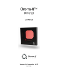
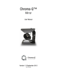
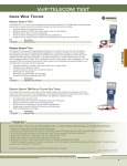
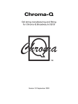
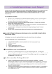
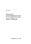
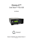
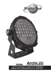
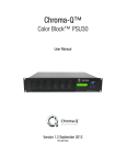
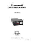
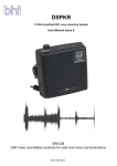
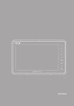
Chroma-Q™
Plus™
User Manual
Version 1.1 January 2006
PN: 103-0078
Disclaimer
The information contained herein is offered in good faith and is believed to be accurate.
However, because conditions and methods of use of our products are beyond our control, this
information should not be used in substitution for customer's tests to ensure that Chroma-Q
products are safe, effective, and fully satisfactory for the intended end use. Suggestions of use
shall not be taken as inducements to infringe any patent. Chroma-Q sole warranty is that the
product will meet the sales specifications in effect at the time of shipment. Your exclusive
remedy for breach of such warranty is limited to refund of purchase price or replacement of any
product shown to be other than as warranted.
Chroma-Q reserves the right to change or make alteration to devices and their functionality
without notice due to our on going research and development.
The Chroma-Q Plus has been designed specifically for the professional entertainment lighting
industry. Regular maintenance should be performed to ensure that the products perform well in
the entertainment environment.
If you experience any difficulties with any Chroma-Q products please contact your selling
dealer. If your selling dealer is unable to help please contact [email protected]. If the
selling dealer is unable to satisfy your servicing needs, please contact the following, for full
factory service:
Outside North America:
Tel: +44 (0)1494 446000
Fax: +44 (0)1494 461024
[email protected]
North America:
Tel: 416-255-9494
Fax: 416-255-3514
[email protected]
For further information please visit the Chroma-Q website at www.chroma-q.com.
Chroma-Q is a trademark, for more information on this visit www.chroma-q.com/trademarks.
The rights and ownership of all trademarks are recognised.
Plus User Manual
1
V1.1 January 2006
Table of Contents
1.
Product Overview ……………………..………………………….………................ 3
2.
Operation ……………...…………………………………………………….………… 4
2.1
Control and power cables ……………………………..……………………. 4
2.2
Gel loading and replacing ……………………………..……………………. 5
2.3
Operating the unit ………………………………………..………………….. 7
2.4
Mounting the unit …….…………………………………..………………… 12
2.5
Safety wire …………………………………………………………………… 12
2.6
Troubleshooting …………………………………………………………….. 12
2.7
Technical overview …………………………………………………………. 13
2.8
Technical specifications ……………………………………………………. 14
3.
Maintenance and storage …………………………………………………………. 15
4.
Drawings ……………………………………………………………………………… 16
4.1
Outside dimensions ………………….……………………………………... 16
4.2
Gel string schematic ………………………………………………………… 17
4.3
Mounting bracket positions ……………………………………………….. 18
Plus User Manual
2
V1.1 January 2006
1.
Product overview
The Chroma-Q Plus takes colour changer technology to a new level. The Chroma-Q Plus is
designed to give years of trouble free use, providing that it is regularly maintained and is used
in accordance with the instructions detailed in this manual. The Chroma-Q Plus is fully
compatible with the Chroma-Q Original.
Note: This manual describes functionality available from version 1.0 of the Chroma-Q Plus
software. For the latest software updates, documentation, and other information about all
Chroma-Q products, please visit the Chroma-Q website at www.chroma-q.com.
The Chroma-Q Plus is designed to operate on the ANSI E1.11 USITT DMX 512-A protocol. This
multiplexed serial data system allows for the individual addressing of multiple units on one data
cabling system. The unit utilises one or two DMX channels depending on the mode of
operation.
The unit is addressed by using the three embossed push button switches and LED display
found on the user interface panel located on the bottom of the body. These switches are also
used to select cooling fan speed, ‘gel saving’ mode, scrolling speed, display lighting, remote
operation, and reset.
Another feature of the user interface panel is a diagnostic section on the LED display showing
Power, DMX signal and signal strength.
•
The first vertical bar indicates that there is Power (24V DC) at the unit.
•
The second vertical bar indicates that there is Data (DMX) at the unit.
•
The horizontal bars indicate the data Signal Level (DMX) at the unit.
- 1st bar = 25-49%
- 2nd bar = 50-74%
- 3rd bar = 75-100%
User Interface Panel
The Chroma-Q Plus is supplied power and control signals by means of two 4-pin XLR style
connectors on the rear panel, allowing multiple units to be ‘daisy-chained’ into the same line of
cabling. Patching the output from the last unit back into the power supply will terminate the
DMX for each chain line and ensure even power voltage across all colour changers in that
chain.
Note: The quantity of Chroma-Q Plus colour changers, and maximum cable length per power
supply output is dependant upon the size of PSU / Splitter box used. (See later in this manual
for details.)
The rear of the unit is designed to accept four point mounting brackets for fixture colour frame
sizes 158mm/6¼” to 254mm/10”. An option with this unit is the innovative Universal Mounting
Bracket which is one bracket that can be adjusted to fixture sizes 158mm/6¼” to 254mm/10”.
Chroma-Q Plus safety information
Warning: This product is for professional use only. It is not for household use.
Read this manual before powering or installing the colour changer, follow the safety
precautions listed below and observe all warnings in this manual and printed on the accessory.
Plus User Manual
3
V1.1 January 2006
If you have question about how to operate the colour changer safely, please contact your
Chroma-Q dealer or e-mail [email protected].
Protection from electric shock
•
Do not expose the colour changer to rain or moisture
•
Refer and service operation not described in this manual to a qualified technician
Protection from burns and fire
•
Keep flammable materials well away from the colour changer
•
Provide a minimum clearance of 0.1m (4 inches) around air vents
•
Do not modify fixture accessory or install other than genuine Chroma-Q parts
Protection from injury due to falls
•
When mounting the colour changer, verify that the fixture frame can hold the weight of
the device
•
Verify that all external covers and rigging hardware are securely fastened and use the
supplied means of secondary attachment, the safety cable.
•
Block access below the work area whenever installing or removing the colour changer.
2.
2.1
2.2
2.3
2.4
2.5
2.6
2.7
2.8
Operation
Control and power cables
Gel loading and replacing
Operating the unit
Mounting the unit
Safety wire
Troubleshooting
Technical overview
Technical specifications
2.1 Control and power cables
The Chroma-Q Plus utilises an XLR 4-pin cable system. This is used for power and data transfer.
Pins 2 and 3 are for ANSI E1.11 USITT DMX 512-A data. Pins 1(-) and 4(+) are for 24VDC power.
Damage will occur if power connections short to data or ground/shield connections. When
assembling XLR 4-pin cables, heat shrink should be used on each individual pin to prevent short
circuits (Tourflex Ultra Datasafe P&D cable recommended). See diagram below.
Note: It is very important to ensure that the drain wire from the cable shield is connected to
both XLR connector cases.
Detail of connector wiring (typical)
Pin #
1
2
3
4
Chassis
Pin #
Ground (-ve)
Control data minus (-)
Control data plus (+)
24V DC (+ve)
Cable shield/drain wire
Minimum Cable size
2.50mm² (14 AWG)
0.35mm² (22 AWG)
0.35mm² (22 AWG)
2.50mm² (14 AWG)
0.25mm² (24 AWG)
Note: Cable length should not exceed 60m/200ft with return line
Plus User Manual
4
V1.1 January 2006
Connections
Correct cabling procedure and connection of the units to the power supply will increase signal
strength and prevent malfunction. Please follow these basic rules.
a)
Use the correct type and gauge of cable and connectors. (Tourflex Ultra Datasafe P&D
cable recommended).
b)
Keep cable runs as short as possible to reduce line loss.
c)
It is recommended to use a return cable for each run. This will ensure balanced DC power
to all units, where the line is correctly terminated, and all units receive power if one link of
the chain is faulty.
Note: Standard signal input is a male XLR chassis connector and output is a female XLR chassis
connector.
Warning: Always ensure that safety wire is connected before final inspection.
2.2 Gel loading and replacing
Introduction
Changing the gel strings is easy, but it may take some time and practice to accomplish, if the
user is not familiar with these types of colour changers.
There are two methods of loading gel strings on the Chroma-Q Plus, manually or using the
power assisted loading method (‘PAL Load’).
Note: It is suggested that new users of this product load the gel strings by the manual method
until they become familiar with the units.
Gel description
The standard gel string consists of a head, gel frames and a tail. Pro Color HT+, Rosco Supergel
and GAMcolor are the recommended media. The head and tail are taped to metal gel tabs
which are then attached to the plastic hooks on the centre of the Take-up Reels (TUR).
Gel string dimensions and assembly
To join a leader, tail and gel together, a high temperature, clear gel tape is recommended.
To join leader and tail to reels, metal gel tabs are required.
Position the gel tab at the end of the gel string. Tape the gel tab to the gel string
both vertically and horizontally
Fold back the gel tab and cut out a notch from the gel string
Plus User Manual
5
V1.1 January 2006
Click the gel tab on the hook of the take up reel
The completed string should look like this:
Note: A range of completed custom gel strings are available upon request. Contact the selling
dealer for details. When ordering gel strings please state the Chroma-Q model the gel string will
be built for.
Warning: Because of the gel saver mode the Chroma-Q Plus the gel strings have a longer
frame. A GL gel string should be used to maximise the effect of this mode. An original gel
string will fit and operate also, but the performance will be compromised.
Manual Loading
1.
Remove Take-up Reel (TUR) by opening lid and pulling out both TUR.
2.
Make hole in gel string at V-notch on tail end and hook tail end of gel string to the black
fixed TUR.
3.
Wind the gel string onto the black TUR.
4.
Hook head end of gel string to the gray Spring Loaded TUR.
5.
Insert both TUR on color changer shafts and DO NOT engage them to the hubs.
6.
Hold black TUR and turn grey TUR 3 full turns to engage spring tension.
7.
Press both TUR down, locking them onto the hub with out releasing the spring tension.
The TURs may need to be rotated a little to locate the hub pins.
8.
Plug in the colour changer, and check that it goes through the initialisation sequence
correctly. Check that the gel runs smoothly and does not bind up on the TUR’s.
9.
Run a test sequence to allow the gel string to ‘bed’ in. The unit does not have to be
attached to a lighting fixture to perform this operation. It is recommended that this
sequence is run for a few minutes (or 3 to 4 times, end-to-end).
Important Notes:
•
For normal operation, the start of the gel string is on the left-side TUR and the end of the
string on the right-side TUR, when viewed from the front of the unit.
•
Do not power lights without powering up the colour changer first. The fan must be
running in order to protect gels from premature failure.
•
High fan speed is recommended on all lighting fixtures of 750 Watts and above.
•
Poorly optimised light bulbs in some fixtures may result in premature gel failure.
Plus User Manual
6
V1.1 January 2006
Power Assisted Loading (‘PAL-Load’)
See also: ‘Operating the unit’ and drawing sections of this manual.
‘PAL-Load’ controls the direction of the Take-up Reels (TUR) with the UP and DOWN button. In
this mode the user can wind and unwind the gel string using the color changer motor. With
practice this will allow for speedier loading and unload of gel strings.
1.
Open lid and remove Take-Up Rollers (TUR) and old gel string if necessary.
2.
Hook tail end of gel string to the black Fixed TUR.
3.
Insert and lock black TUR and gel string into color changer. The TUR may need to be
rotated a little to locate the hub pins.
4.
Apply power to the unit while holding down the MENU button.
The display will show the legend PAL.
5.
Press and hold DOWN until gel string is wound onto black TUR.
6.
Insert grey TUR on color changer shafts and DO NOT engage it to the hub.
7.
Hold black TUR and turn gray TUR 3 full turns to engage spring tension.
8.
Press grey TUR down, locking it into the hub with out releasing the spring tension. The
TUR may need to be rotated a little to locate the hub pins.
9.
Allow the unit to self-calibrate by pressing the UP and DOWN buttons simultaneously, or
by unplugging and re-plugging the colour changer.
10. Run a test sequence to allow the gel string to ‘bed’ in. The unit does not have to be
attached to a lighting fixture to perform this operation. It is recommended that this
sequence is run for a few minutes (or 3 to 4 times, end-to-end).
2.3 Operating the unit
All the unit functions are accessed using the LED display and the three push-button switches on
the bottom panel.
Control
MENU Button
UP Button
DOWN Button
3 digit display
Function
Mode access, record and escape
Decrements (-) the mode level or value
Increments (+) the mode level or value
Displays mode, monitor or blank display
Control description
The MENU button is used to scroll through the different modes of operation, and the UP or
DOWN buttons used to select the level, or value, in that mode.
If any mode or value is changed the display will begin flashing;
•
To restore the previous value, press and release the MENU
•
To record the change depress and hold the MENU button for 2 seconds or until last
character stops flashing
Display operation
Power-up display
On power-up, the unit will go through its self-calibration mode and the
display will show the units software version. (i.e. 1.0.0)
Plus User Manual
7
V1.1 January 2006
After the self-calibration finishes, the display will show the DMX address
mode. (i.e. 0.0.1)
Monitor Display
If left undisturbed for 5-7 seconds, the display will revert to ‘Monitor Mode’
•
•
•
The first vertical bar indicates that there is Power (24V DC) at the unit.
The second vertical bar indicates that there is good Data (DMX) at the unit.
The horizontal bars indicate the data Signal Level (DMX) at the unit.
- 1st bar = 25-49%
- 2nd bar = 50-74%
- 3rd bar = 75-100%
See also: ‘Troubleshooting’ section of this manual.
Display Flip
The display-viewing angle can be flipped through 180º by pressing the MENU and DOWN
button simultaneously.
Display Mode
The display can be set to auto-blackout after 12 seconds. This is selected through the mode
menu under ‘dP’, where dP0 is OFF and dP1 is ON.
Reset
If the MENU and the UP button are pressed and held for 1 second, the unit
will reset to the factory default settings. This feature is particularly useful
when the units are used in many different configurations or shows.
The reset function is also available through ‘Remote Operation’
Modes of operation
Important Notes:
• The MENU button is used to scroll through the different modes of operation, and the UP or
DOWN buttons used to select the level or value, in that mode.
• If any mode or value is changed, the display will flash until the MENU button is pushed and
held for 2 seconds to record the change.
• When the MENU button is held for 2 seconds, the unit will save the change(s) and these
‘user defaults’ will take precedence immediately.
• If MENU button is not held for 2 seconds to previous value will be displayed
• The unit will not save any change(s) made by remote control after the next power cycle.
DMX addressing mode
This mode is used to set DMX data address of the unit. The unit uses one or two DMX channels
depending which mode it is operating.
The display shows the current DMX address (between 1 and 512).
To alter the address, press UP or DOWN button once to increment or decrement the value; hold
down the UP or DOWN for fast increments and decrements of the value.
See also: ‘Remote Operation’ later in this section.
Plus User Manual
8
V1.1 January 2006
Fan speed mode (Fn)
This mode is used to set the gel cooling-fan speed of the unit. This feature can be used in
environments where a lower noise level is required, although this may decrease gel string life.
The display shows the current gel cooling fan speed. There are four fan speeds, 1 is the slowest
and 4 is the fastest.
Press UP or DOWN once to increment or decrement the value.
See also: ‘Remote Operation’ later in this section.
Gel saver mode (GL)
Gel-saver mode is used to switch the gel-saving mode on or off. This feature slowly moves the
chosen gel frame back and forward slightly so that the heat build-up is dissipated over a larger
area, extending the life of the gel string. Press the UP or DOWN buttons once to switch between
On (1) and Off (0) (the default is Off). Press hold MENU for 2 seconds to save the new setting.
This feature is also available via DMX (see "Remote operation" section of this manual).
A Chroma-Q Plus gel string should be installed to maximise the effect of this mode.
Speed mode (SP)
This mode is used to set the scrolling speed of the unit. This feature allows the gel string to
move at a higher speed, for more rapid changes. Use of this high speed will generate more
noise from the unit. Press the UP or DOWN buttons once to switch between Standard (1) and
Fast (2) (the default is Standard). Press and hold MENU for 2 seconds to save the new setting.
This feature is also available via DMX (see "Remote operation" section of this manual).
Display mode (dP)
This mode is a two step feature set with the UP and DOWN button, on (1) and off (0). Default is
off (0). When set to dP1 the display will change to diagnostic mode after 6 seconds. When set to
dP0 the display will change to the diagnostic mode in 6 seconds, then clear in another 6
seconds, making 12 seconds till auto-blackout. The display will return to diagnostic mode with
the first button press and will do the action of the second press.
Remote Operation mode (ro)
This mode is used to switch between the different remote operation modes in the unit. The use
of these different modes greatly enhances the versatility of the unit by giving the user remote
control of some functions.
There are three remote operation modes:
Mode 1 = Single-channel DMX operation. The channel controls the colour selection.
Mode 2 = Dual-channel DMX operation. The 1st channel controls the colour
selection. The 2nd channel controls the fan speed;
0-24%= Fn 4(fast), 25-49% = Fn3, 50-74% = Fn2, 75-100% = Fn1 (slow).
Mode 3 = Dual-channel DMX operation. The 1st channel controls the colour
selection. The 2nd channel controls the units other functions.
These functions
Ch. 2 Level
Feature
initialise two
0-5%
= No feature
seconds after
6-15%
= Fan off
the channel level
16-25%
= Fan speed 1 (slowest)
is entered.
26-35%
= Fan speed 2
36-45%
= Fan speed 3
46-55%
= Fan speed 4 (fastest)
56-65%
= Gel Saver off
66-75%
= Gel Saver on
76-85%
= Motor speed normal, see Speed mode (SP)
86-95%
= Motor speed fast, see Speed mode (SP)
96-99%
= Reset (reset to user defaults)
The display shows the current Remote Operation mode of the unit.
Press UP or DOWN to increment or decrement the mode setting.
Plus User Manual
9
V1.1 January 2006
Default Settings
‘Factory’ default settings
If the MENU and the UP button are pressed and held for 1 second, the unit
will reset to the factory default settings. This feature is particularly useful
when the units are used in many different configurations or shows.
The reset function is also available through ‘Remote Operation’
The ‘Factory’ default settings put the unit in the manufacturer
operating mode.
Fan Speed =4 (fast)
Gel Saver =0 (Off)
Gel Speed =1 (slow)
Display =1 (On)
Rmt.1 (normal)
Operation = standard
Display Flip =
‘User’ default settings
Each time the MENU button is pressed and held for 2 seconds, the unit will save that change
and these ‘user defaults’ will take precedence immediately.
These ‘User’ defaults can be reset to the ‘factory’ defaults using the method detailed above.
Summary of control functions
Operation or Description
Mode
Power-Up
Software version
shown on the unit(s)
at power-up.
reSet
This will reset the
unit to the default
settings.
Power
Used to load a gelAssisted
string into the unit.
Loading
(‘PAL-Load’)
Actions required
Display
This shows the software version while the
unit is self-calibrating, before displaying the
‘Monitor Mode’.
While holding down MENU and DOWN
button for 1 second.
Hold down the MENU button during powerup. Pressing the UP button will advance the
fixed TUR. Pressing the DOWN button will
advance the spring TUR. Press both DOWN
& UP buttons, or cycle the power, to recalibrate.
See also, gel loading instructions
Modes (Use the MENU button to scroll through these modes)
DMX
Used to set the units The display shows DMX address (1-512).
addressing DMX data address
Press DOWN or UP once to increment or
Mode
decrement the value, hold down the DOWN
or UP for fast increment or decrement.
See also, DMX addressing instructions
Fan speed
Used to set the fan The display shows the current gel cooling
Mode
speed of the unit. fan speed. There are four fan speeds, 1 is
the slowest and 4 is the fastest.
Press UP or DOWN once to increment or
decrement the value,
See also, fan speed instructions
Plus User Manual
10
V1.1 January 2006
‘Gel Saver’
Mode
Switches on/off the
gel saving mode.
The display shows the current gel saver
mode.
Press UP or DOWN once to switch between
on (1) and off (0).
See also, gel saver mode instructions
‘speed’
Used to set the
The display shows the current gel scrolling
Mode
scrolling speed of the speed. There are two scrolling speeds. 1 is
unit.
the slowest, 2 is the fastest.
Press UP or DOWN once to increment or
decrement the value,
See also, gel scroll speed instructions
‘disPlay’
Switches on/off the Switches the display on or off. Display will
Mode
display
re-activate when any button is pressed.
Press UP or DOWN to switch between on(1)
and off(0).
See also, display mode instructions
‘remoteMode1 =single DMX The display shows the current DMX mode
operation’
channel operation.
of the unit. There are three DMX modes
Mode 2 = Dual DMX Press UP or DOWN button to increment or
channel operation
decrement the mode setting,
(Colour/Fan speed)
Mode 3 = Dual DMX
channel operation
(Colour/Function)
2.4 Mounting the unit
The Chroma-Q Plus is designed to mount in a variety positions but with the base of the unit
below the fixture. Do not mount in an inverted position with the base of the unit above the
fixture, as the rising heat from the fixture may cause the gel string damage.
The rear of the unit has four re-enforced mounting stands with an M4 sleeved thread inserted.
The spacing of these stands are set to accommodate standard mounting brackets for fixture
colour frame sizes of 158mm/6¼”, 190mm/7½”, 215mm/8 ½”, and 254mm/10”.
Also available is the Universal Mounting Bracket shown below. This is one bracket that can be
adjusted to fixture sizes from 158mm/6¼” to 254mm/10”, Chroma-Q part number 110-0109.
Anchor Point
158mm/6¼”
Plus User Manual
190mm/7½”
11
254mm/10”
V1.1 January 2006
This Universal Bracket has two pairs of threaded holes for each leaf, and each leaf has two slots
and two alignment holes. Four frame sizes are achievable;
•
To set the frame size to 158mm (6 ¼”) use the inner threaded holes on the bracket and
align the outer hole on the leaf with the inner hole on the bracket.
•
To set the frame size to 190mm (7 ½”) use the outer threaded holes to secure the leaf and
align the outer hole on the leaf with the outer hole on the bracket.
•
To set the frame size to 254mm (10”) remove the leafs.
The leaves and bracket have holes which align to 158mm (6¼”), 190mm (7½”), and 215mm
(8½”). The leaves can be removed to give a 254mm (10”) mounting frame.
See section 5 for all possible frame connections
2.5 Safety wire
The Chroma-Q Plus should always be used with the safety wire provided.
2.6 Troubleshooting
The LED display aids in the troubleshooting of the Chroma-Q Plus system. These indicators are
located on the bottom of each unit.
•
•
•
The first vertical bar indicates that there is Power (24V DC) at the unit.
The second vertical bar indicates that there is Data (DMX) at the unit.
The horizontal bars indicate the data Signal Level (DMX) at the unit.
- 1st bar = 25-49%
- 2nd bar = 50-74%
- 3rd bar = 75-100%
Note: The signal level changes during normal operation of the unit.
Symptom
Unit does not respond to
DMX control, but DMX
display indicator is on.
Unit does not respond to
DMX, DMX display indicator
is off.
Units run at different speeds.
Chroma-Q Plus units have dim
display indicators and run
slowly.
DMX display indicator is off
on one unit.
Plus User Manual
Possible Cause
Unit set to wrong DMX
address.
Solution
Check DMX address settings.
Bad Cable.
No DMX at Splitter/ PSU.
Check cable and DMX run
from console.
Colour changer speed
settings may be different.
Cable lengths are too long.
No cable return line.
Check all colour changer
speed settings.
Check the cable length and
configuration.
Ensure there is a cable return
line in the system.
Check voltage levels on last
unit. Should not be below
20VDC.
Check cable
Cable runs too long.
Too many units on one chain
overloading PSU.
Colour changer not
connected.
Bad cable.
Damaged transceiver IC in the
colour changer.
12
Send unit back for repair.
V1.1 January 2006
Display Indicators appear OK
but gel string does not move.
Gel burns too quickly.
Mechanical (or electrical)
failure in the unit.
Fans have failed or are too
slow.
Poorly optimised lamp focus
in fixture.
IR filter medium not fitted.
Turn unit on and off.
Return unit for repair.
Check fans are operating.
Optimise bulb focus.
Replace gel strings and install
IR filter.
Note: A high percentage of problems are a direct result of poor cable and corrupt DMX control
signals.
2.7 Technical overview
The colour transport system employs an opto-electronic system for accurate positioning of the
gel string. When the unit initially receives power it will go through a calibration sequence. The
purpose of the initial calibration sequence during power up is to determine the total length of
the gel string and therefore the position of the different gels.
Note: Over time the gel string may warp slightly. This may alter the positions of the gels relative
to their pre-programmed DMX values and therefore some ‘fine-tuning’ may be required.
The motor has an optical encoder feedback system. The purpose of this is to convert motor
revolutions in to electronic pulses, and also to determine which direction the motor is turning.
The electronic cards consist of three key components: L6225 motor driver, 75176 transceiver
and a processor. The L6225 is a true digital device receiving two PWM signals to operate speed
and direction. The 75176 transceiver operates in the receive configuration to convert serial
protocol to a TTL level. All data relevant to the operation of the unit is stored onboard in ‘flash’
memory.
The majority of electronics problems are usually created by external factors such as shorted
cables, etc. The 75176 transceivers are susceptible to damage if 24VDC is present on the DMX
signal lines.
Routine maintenance can prevent most mechanically based problems. The motor mounting
plate can be adjusted to control tension on the belt. Excessive belt tension is often the cause of
noise and poor performance. Conversely, loose motor belts can cause accuracy problems.
Troubleshooting is a process of elimination. First, rule out the other field factors (i.e. faulty
cables, power sources). If an electronics problem is suspected inside the unit replace the
electronics card first. If accuracy problems should occur and mechanical problems have been
ruled out, replace optical sensors. For technical advice and or parts, please contact your selling
dealer or the offices listed in this manual.
2.8
Technical specifications
Dimensions:
286mm (w) X 297mm(h) X 92mm(d)
11.25” (w) X 11.69” (h) X 3.61 ” (d)
Weight:
2.04kg / 4.5 lb (without mounting frame)
Aperture:
171mm / 6.75”
Colour media:
Pro Color HT+, Rosco and GAMcolor recommended
Gel capacity:
2-20 frames
Cooling:
Forced air
Cooling speed:
4 speeds
Addressing:
Digitally, via push buttons (3) and LED display
Plus User Manual
13
V1.1 January 2006
Working Voltage:
24 VDC (+/- 10%)
Power consumption:
1 Power Unit (PU) (see note below)
DMX protocol:
ANSI E1.11 USITT DMX 512-A
Body material:
UL94 V0 rated reinforced PBT compound
Body color:
Black (white option)
Mounting plate:
Optional fixed or universal mounting system fits 160-254mm/
6¼”-10” fixtures
Connectors:
European approvals:
XLR-4 (male) in and XLR-4 (female) through
Complies with EU directives: EMC89/336/EECClass A.
Harmonised standards applied in order to verify compliance with
directives: EN 56022:1994, EN50082-1: 1992 & EN 60950
Radiated Emissions: Complies with FCC part 15 subpart B, class
A for unintentional radiators. Low Voltage Directive: Complies
with CSA 22.2 950, UL 1950
North American approvals:
Note: We use the Power Unit (PU) to simplify the load calculation on any given Chroma-Q
power supply. For example a PSU12 will supply up to 12 PU. So you can plug-in 12 Chroma-Q
Plus, 8 Chroma-Q Universal, or a combination of 8 Chroma-Q Plus and 4 Chroma-Q Universal
on one PSU08.
3.
Maintenance and storage
The Chroma-Q Plus should be stored in a dry and cool environment, safely secured to prevent
from falling on a hard surface.
The unit may be exposed to dirty environments containing many air particles. This can lead to
dust and dirt build-up in the vents and fan area. The unit should be vacuumed to remove dust
and dirt. This can be done with a painters brush and vacuum. Simply brush the dust out of the
vents and fan into a vacuum cleaner. DO NOT use compressed air to blow dust and dirt into the
unit.
If there is any oily residue on the body of the unit or the gel string wipe off with a damp cloth
ensuring that no water enters the fan or vent area affecting the electronics.
The gel string should be inspected for wrinkling and cracking. If there are signs of wear a new
gel sting should be installed.
Plus User Manual
14
V1.1 January 2006
4.
4.1
Drawings
Outside dimensions of the unit
Plus User Manual
15
V1.1 January 2006
4.2 Gel string schematic
Plus User Manual
16
V1.1 January 2006
4.3
Mounting bracket positions
MP3/6¼”
MP2/7½”
MP1/10”
MPU 158mm/6¼”
MPU 190mm/7½”
MPU 215 (8½”)
MPU 254mm/10”
Plus User Manual
17
V1.1 January 2006