1
Current Source/
Measure Module
52956
User’s Manual
Version 1.1
June 2007
Legal Notices
The information in this document is subject to change without notice.
Chroma ATE INC. makes no warranty of any kind with regard to this manual,
including, but not limited to, the implied warranties of merchantability and
fitness for a particular purpose. Chroma ATE INC. shall not be held liable for
errors contained herein or direct, indirect, special, incidental or consequential
damages in connection with the furnishing, performance, or use of this
material.
CHROMA ATE INC.
No. 66 Haw-Ya 1st Rd, Hwa-Ya Technical Park, Kuei-Shan Hsiang, Taoyuan
Hsien 333, Taiwan
Copyright Notices. Copyright 2006- 2007 Chroma ATE INC., all rights
reserved. Reproduction, adaptation, or translation of this document without
prior written permission is prohibited, except as allowed under the copyright
laws.
Trademarks
LabVIEW®, LabWindows/CVI® 6.0, MAX®, IVI® and VISA® are trademarks
of National Instruments Corporation.
Microsoft® Visual C++® 6.0 and Microsoft Visual Basic® 6.0 are trademarks of
Microsoft Corporation.
Borland® C++ are trademarks of Borland Corporation.
Product and Company names are trademarks or trade names of their respective
companies.
ii
Warranty
All Chroma instruments are warranted against defects in material and
workmanship for a period of one year after date of shipment. Chroma agrees
to repair or replace any assembly or component found to be defective, under
normal use during this period. Chroma's obligation under this warranty is
limited solely to repairing any such instrument, which in Chroma's sole opinion
proves to be defective within the scope of the warranty when returned to the
factory or to an authorized service center. Transportation to the factory or
service center is to be prepaid by purchaser. Shipment should not be made
without prior authorization by Chroma.
This warranty does not apply to any products repaired or altered by persons not
authorized by Chroma, or not in accordance with instructions furnished by
Chroma. If the instrument is defective as a result of misuse, improper repair,
or abnormal conditions or operations, repairs will be billed at cost.
Chroma assumes no responsibility for its product being used in a hazardous or
dangerous manner either alone or in conjunction with other equipment. High
voltage used in some instruments may be dangerous if misused. Special
disclaimers apply to these instruments. Chroma assumes no liability for
secondary charges or consequential damages and in any event, Chroma's
liability for breach of warranty under any contract or otherwise, shall not
exceed the purchase price of the specific instrument shipped and against which
a claim is made.
Any recommendations made by Chroma for use of its products are based upon
tests believed to be reliable, but Chroma makes no warranty of the results to be
obtained. This warranty is in lieu of all other warranties, expressed or implied,
and no representative or person is authorized to represent or assume for
Chroma any liability in connection with the sale of our products other than set
forth herein.
CHROMA ATE INC.
No. 66 Haw-Ya 1st Rd, Hwa-Ya Technical Park,
Kuei-Shan Hsiang, Taoyuan Hsien 333, Taiwan
Tel: 886 -3-327-9999
Fax: 886-3-327-3990
http://www.chromaate.com
iii
Material Contents Declaration
A regulatory requirement of The People’s Republic of China defined by
specification SJ/T 11364-2006 mandates that manufacturers provide material
contents declaration of electronic products, and for Chroma products are as
below:
Hazardous Substances
Lead
Mercury
Cadmium
Hexavalent
Polybrominated Polybromodiphenyl
Part Name
Chromium
Biphenyls
Ethers
Pb
Hg
Cd
Cr6+
PBB
PBDE
PCBA
O
O
O
O
O
CHASSIS
O
O
O
O
O
ACCESSORY
O
O
O
O
O
PACKAGE O
O
O
O
O
O
“O” indicates that the level of the specified chemical substance is less than the
threshold level specified in the standards of SJ/T-11363-2006 and EU
2005/618/EC.
“ ” indicates that the level of the specified chemical substance exceeds the
threshold level specified in the standards of SJ/T-11363-2006 and EU
2005/618/EC.
1.
2.
Chroma is not fully transitioned to lead-free solder assembly at this
moment; however, most of the components used are RoHS compliant.
The environment-friendly usage period of the product is assumed under the
operating environment specified in each product’s specification.
Disposal
Do not dispose of electrical appliances as unsorted municipal waste, use
separate collection facilities. Contact your local government for information
regarding the collection systems available. If electrical appliances are disposed
of in landfills or dumps, hazardous substances can leak into the groundwater
and get into the food chain, damaging your health and well-being. When
replacing old appliances with new one, the retailer is legally obligated to take
back your old appliances for disposal at least for free of charge.
iv
Revision History
The following lists the additions, deletions and modifications in this manual at
each revision.
Date
Version Revised Sections
Nov. 2006 1.0
Complete this manual.
June 2007 1.1
Add “Material Contents Declaration”.
Modify related contents to comply with the new functions.
v
Current Source/Measure Module 52956 User’s Manual
Table of Contents
1. Introduction ...................................................................................................1-1
1.1
1.2
1.3
Product Description...........................................................................1-1
Opening the Package and Checklist ..................................................1-1
1.2.1
1.2.2
Opening the Package.............................................................................. 1-1
Checklist ................................................................................................ 1-2
Features .............................................................................................1-2
2. Drivers Installation........................................................................................2-1
2.1
2.2
2.3
2.4
Driver CD..........................................................................................2-1
Installing the Software.......................................................................2-1
Installing the Hardware .....................................................................2-1
2.3.1
2.3.2
Device Driver Installation on Windows 2000 ........................................ 2-2
Device Driver Installation on Windows XP ........................................... 2-2
Hardware Verification .......................................................................2-2
3. Application .....................................................................................................3-1
3.1
3.2
3.3
3.4
3.5
3.6
The Demand for Laser Diodes ..........................................................3-1
Overview of Laser Diode Testing......................................................3-1
Understanding Laser Diode LIV Testing...........................................3-2
Test Setup ..........................................................................................3-5
3.4.1
3.4.2
3.4.3
Laser Diode Current Source................................................................... 3-5
Optical Power Meter .............................................................................. 3-6
Temperature Controller .......................................................................... 3-6
Dealing with Tunable Laser Diodes ..................................................3-7
Multi-Head Test.................................................................................3-8
4. Software..........................................................................................................4-1
4.1
4.2
Block Diagrams.................................................................................4-1
User Programs ...................................................................................4-1
5. Basic Operation..............................................................................................5-1
5.1
5.2
5.3
5.4
Block Diagrams.................................................................................5-1
Manual Mode ....................................................................................5-2
5.2.1
How to Use Soft Front Panel (SFP) ....................................................... 5-2
5.4.1
5.4.2
5.4.3
5.4.4
5.4.5
Overview...............................................................................................5-11
Data Table Creation and Upload .......................................................... 5-13
Running a Sequence............................................................................. 5-15
Downloading the Results Data Table ................................................... 5-16
Types of Sequence................................................................................ 5-17
Computer Controlled – Simple Automation ....................................5-10
Sequence Mode ...............................................................................5-10
vii
Current Source/Measure Module 52956 User’s Manual
5.4.6
Data Formats on the Sequencer............................................................ 5-19
6. DLL Calls and Example Programs ..............................................................6-1
6.1
6.2
6.3
DLL Calls ..........................................................................................6-1
6.1.1
6.1.2
6.1.3
6.1.4
6.1.5
6.1.6
6.1.7
6.1.8
6.1.9
6.1.10
6.1.11
6.1.12
6.1.13
6.1.14
6.1.15
6.1.16
6.1.17
6.1.18
6.1.19
6.1.20
6.1.21
6.1.22
6.1.23
6.1.24
6.1.25
6.1.26
6.1.27
6.1.28
6.1.29
6.1.30
6.1.31
6.1.32
6.1.33
6.1.34
6.1.35
6.1.36
6.1.37
chr52956_init ......................................................................................... 6-1
chr52956_InitWithOptions..................................................................... 6-3
chr52956_close ...................................................................................... 6-6
chr52956_SetComplianceVoltage .......................................................... 6-7
chr52956_SetCurrent ............................................................................. 6-8
chr52956_SetWireMode ........................................................................ 6-9
chr52956_SetOutputRange .................................................................. 6-10
chr52956_ConnectOutput .....................................................................6-11
chr52956_DisonnectOutput ................................................................. 6-12
chr52956_SetMeasureAverage............................................................. 6-13
chr52956_SetTriggerSetup................................................................... 6-14
chr52956_SetMasterMode ................................................................... 6-15
chr52956_SetLocalRelay ..................................................................... 6-16
chr52956_SetHWTriggerMode............................................................ 6-17
chr52956_SetMaximumCurrent........................................................... 6-18
chr52956_ReadMaximumCurrent........................................................ 6-19
chr52956_GetRelayThresholds ............................................................ 6-20
chr52956_SetRelayThresholds............................................................. 6-22
chr52956_UpdateRelayInfoToEEPROM ............................................. 6-24
chr52956_ReadVoltage ........................................................................ 6-25
chr52956_SequenceRunMaster............................................................ 6-26
chr52956_SequenceRunSlave .............................................................. 6-27
chr52956_SequenceReset..................................................................... 6-28
chr52956_SequenceWriteHeaderBlock................................................ 6-29
chr52956_SequenceReadHeaderBlock ................................................ 6-30
chr52956_SequenceWriteBlockHeader................................................ 6-31
chr52956_SequenceReadBlockHeader ................................................ 6-32
chr52956_SequenceWriteBlockData.................................................... 6-33
chr52956_SequenceReadBlockData .................................................... 6-34
chr52956_SequenceWriteBlockDataArray .......................................... 6-35
chr52956_SequenceReadBlockDataArray ........................................... 6-36
chr52956_SetSequenceRunLoopMultiplier ......................................... 6-37
chr52956_SequenceStatus.................................................................... 6-38
chr52956_reset ..................................................................................... 6-39
chr52956_error_message ..................................................................... 6-40
chr52956_ReadRangeLimit ................................................................. 6-41
Other Driver Functions ........................................................................ 6-42
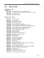
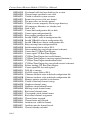
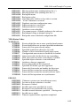
Error Code.......................................................................................6-43
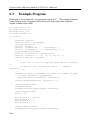
Example Program............................................................................6-48
7. Hardware Overview ......................................................................................7-1
7.1
viii
Hardware Block Diagram..................................................................7-1
Current Source/Measure Module 52956 User’s Manual
7.2
7.3
7.4
7.5
7.6
Hardware ...........................................................................................7-2
7.2.1
7.2.2
7.2.3
Backplane Bus Section........................................................................... 7-2
Sequence Engine Section ....................................................................... 7-3
Analogue Section ................................................................................... 7-5
7.3.1
Hardware Overview ............................................................................... 7-6
7.6.1
7.6.2
Stimulus & Measurement..................................................................... 7-10
Measurement Only................................................................................7-11
High Speed Instrument Sequencer (HSIS) Overview .......................7-6
7.7
7.8
7.9
7.10
Trigger Bus Interface.........................................................................7-7
Local Bus Interface ...........................................................................7-8
Synchronization.................................................................................7-9
Data Table Format ...........................................................................7-12
Front Panel Connectivity.................................................................7-13
Wire Mode.......................................................................................7-15
Configuration ..................................................................................7-16
8. Hardware Specification.................................................................................8-1
ix
Introduction
1.
Introduction
1.1
Product Description
Chroma 52956 Current Source/Measure Module is primarily designed for Laser
Diode Test applications. However, it is a versatile instrument and can be used in
many other applications. It allows the user to provide an accurate and constant
current stimulus required by Laser Diodes and measure the resultant forward
voltage drop of the Laser Diode during automated test sequence or manual testing.
The user can generate a table of different stimulus values and step rapidly through
these using the High Speed Instrument Sequencer (HSIS) functionality of the
52956 module. At each step, the resultant potential can be read back into a table,
which can be uploaded from the module to the test systems database. A
compliance voltage is programmable on the source to prevent voltage excursions
outside programmed limits.
The unit is intended to provide the drive current for a Laser Diode during test or
characterization of the device. Multiple units will be required to work in
combination when testing / characterizing tunable Laser Diodes.
Compliant to PXI and cPCI Standards
The 52956 Current Source/Measure Module is complying with the latest PXI
Revision 2.0 specifications of the PXI System Alliance (PXISA) as well as the
CompactPCI specifications as defined by the PCI Industrial Computer
Manufacturing Group (PICMG). Both cards are fully compliant with these
specifications and as such can be used in either PXI or CompactPCI chassis.
1.2
Opening the Package and Checklist
1.2.1
Opening the Package
Open the 52956 Current Source/Measure Module package carefully and inspect if
all hardware are in good condition without any damages and if the Compact Disc
is broken or unreadable. If any damage is found and caused the hardware or
software application unable to execute, return the product in its original package
and contact us.
1-1
Current Source/Measure Module 52956 User’s Manual
1.2.2
Checklist
The 52956 kit contains the following items:
A PXI 52956 Current Source/Measure Module
A CD containing test software and drivers, and user’s manual
1.3
Features
1-slot, 3U PXI card
PXI 1.0 compliant with PXI trigger bus and local bus support
CompactPCI R PICMG 2.1-R1.0 Hot Swap ready compliant
Integrate on a master slave basis with other 52956’s or other Chroma
Photonics Cards
High Speed Real Time Sequence Engine 5000 current steps
Fully floating output allowing star ground connections for multiple units
2MB on board memory for data storage and sequence instructions
Voltage measurement with Kelvin connection
16-bit stimulus and measure
Compliance voltage programmable from 0V to 8V
Small footprint / PXI Modular Architecture
Calibration data stored in on-board NV Ram
Instrument drivers are based on NI-VISA and NI-IVI
Instrument drivers support NI LabVIEW, NI LabWindows/CVI, Microsoft
Visual C++, Microsoft Visual Basic and Borland C++ Builder
Soft front panel and example program for Windows 2000/XP
1-2
Drivers Installation
2.
Drivers Installation
2.1
Driver CD
The driver CD contains the following programs and files:
Windows 2000, Window XP device drivers
52956 soft front panel and program examples
The instrument drivers and libraries are supported as listed below:
- NI LabVIEW® Ver. 6.1, 7.0, 7.1 & 8.01
- NI LabWindows/CVI® Ver. 6.0
- Microsoft Visual C++® Ver. 6.0
- Microsoft Visual Basic® Ver. 6.0
- Borland C++ Builder® Ver. 5.0
2.2
Installing the Software
The 52956 instrument drivers are based on National Instruments VISA and IVI.
Please install NI-VISA 3.1 and NI-ICP 2.0 (or newer version) before installing
52956 instrument drivers.
Select Start and choose RUN. Click Browse and locate the file
"X:\SETUP.exe" (where 'X' is the drive the CD is in), then execute it. The
default installation directory is C:\Program Files\Chroma\pxi\52956. It is
recommended to use this path as installation directory. Please follow the
prompts to complete the installation procedure.
Note: To install the device driver on Windows 2000 or Windows XP, you should
log on as the “administrator”.
2.3
Installing the Hardware
Step 1.
Step 2.
Make sure the chassis is powered off.
Select a slot in the chassis and install the 52956 Current
Source/Measure Module carefully, then secure it with the screws on
the panel.
Step 3. Power the chassis up and boot Windows.
2-1
Current Source/Measure Module 52956 User’s Manual
2.3.1
Device Driver Installation on Windows 2000
Step 4.
“Found New Hardware Wizard” will show up after Windows 2000
booting. Click Next >.
Choose “Search for a suitable driver for my device (recommended)”.
Click Next >.
Unselect all “Optional Search locations”. Click Next >.
The wizard found “52956 Current Source/Measure Module”. Click
Next >.
Click Finish to finish device driver installation on Windows 2000.
Step 5.
Step 6.
Step 7.
Step 8.
2.3.2
Step 4.
Step 5.
Step 6.
Step 7.
Step 8.
2.4
Device Driver Installation on Windows XP
“Found New Hardware Wizard” will show up after Windows XP
booting. Click Next >.
Choose “Search for a suitable driver for my device (recommended)”.
Click Next >.
Unselect all “Optional Search locations”. Click Next >.
The wizard found “52956 Current Source/Measure Module”. Click
Next >.
Click Finish to finish device driver installation on Windows XP.
Hardware Verification
Follow the description below to verify if the 52956 is properly installed and
working.
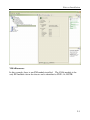
National Instruments VISA Interactive Control (MAX)
The National Instruments software application, VISA Interactive Control, can
be used for verification. This is a program to identify the installed VISA
resources including PXI resources as shown below.
2-2
Drivers Installation
VISA Resources
In this example, there is one PXI module installed. The 52956 module is the
only PXI module slot in the chassis and is identified as PXI2::14::INSTR.
2-3
Application
3.
Application
Chroma 52956 Current Source/Measure Module can be used in many different
applications where multiple stimuli and or measurements are required to be
taken over a short period of time. As with any process, the shorter the time
taken, the more efficient the process is. One application for this product is
testing & characterization of Laser Diodes & Tunable Laser Diodes. This
application section is prepared by Dr Gerald Farrell.
3.1
The Demand for Laser Diodes
In the last few years the demand for more and more bandwidth in
telecommunications networks has lead to an ever increasing demand for multi
channel Dense Wavelength Division Multiplexed (DWDM) systems. At
present vendors are offering systems that can provide more than 100 channels,
with the promise of even higher channel counts in the near future. Each
channel uses a laser diode as a source and thus a consequence of the increased
demand for bandwidth is that the volume of laser diodes being produced for
telecommunications applications is increasing faster than ever before. In turn
this means that manufacturers of laser diodes not only need economic and
accurate laser diode testing, but this testing must take place at high speed.
This article provides an overview of laser diode testing at manufacturer,
highlighting the tests that need to be carried out and also describing a typical
ATE based laser diode test setup.
3.2
Overview of Laser Diode Testing
A completed Laser Diode Module (LDM) will typically contain several other
components, such as a back-facet power monitor photodiode and possibly a
thermoelectric cooler. As a result the completed module is complex and
requires testing at several stages during assembly. Coupled to the increasing
demand for laser diodes the need for multiple testing stages means that speed of
testing, while retaining accuracy, is now a critical issue.
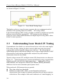
Laser diode testing takes place from the raw laser chip stage to the completed
module stage. The typical testing stages for a telecommunications laser diode
3-1
Current Source/Measure Module 52956 User’s Manual
are shown in Figure 3-1 below.
Figure 3-1
Laser Diode Testing Stages
The higher up the test stage the more expensive the test equipment involved
and the cost of rejecting faulty laser diodes. DC testing, called
Light-Current-Voltage (LIV) testing, provides an initial test which can typically
measure several key laser parameters. LIV testing can also eliminate
below-par lasers which could ultimately fail higher up the testing chain, where
failure is more expensive.
3.3
Understanding Laser Diode LIV Testing
Semiconductor laser diodes are current driven devices and as the name implies
LIV testing involves altering the drive current while measuring the optical
output power and the forward voltage across the laser. By measuring the
optical output power and forward voltage over a range of input currents an LIV
characteristic can be built up which when analyzed can yield valuable
information about the laser diode.
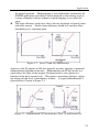
Typical voltage-current (VI) and light-current (LI) characteristics are shown in
Figure 3-2. Optical output power can measured directly using an optical fiber
aligned precisely with the laser diode output facet. Additionally all laser
diode modules also incorporate a Back-Facet Monitor (BFM) photodiode,
which can also be used to monitor optical power levels.
When analyzed a LI characteristic can provide:
The value of the laser threshold.
Evidence of undesirable “kinks” or non-linearities in the laser
characteristic that can point to inherent problems that will mean rejection
of the device. For example a kink can be indicative of “mode hopping” in
3-2
Application
the optical spectrum. Mode hopping is very undesirable, particularly for
DWDM applications and while it can be detected at after testing stages it
is more economic to detect evidence of mode hopping at an earlier test
stage.
The slope efficiency of the laser, that is the rate of change of optical power
with drive current. Ideally slope efficiency should be a constant above
threshold up to a saturation point.
Figure 3-2
Laser VI and LI Characteristics
Analysis of the LI portion of LIV data typically involves applying a numerical
differentiation algorithm to the data. Differentiating the LI data results in a
graph where the slope of the original LI characteristic is now plotted as a
function of the drive current level. This process accentuates changes, such as
the change in light level at threshold or at kinks. A typical differentiated LI
characteristic is shown in Figure 3-3.
Figure 3-3 - Differentiated LI Characteristics (First (a) and Second (b))
3-3
Current Source/Measure Module 52956 User’s Manual
In Figure 3-3(a) the original LI data and the first differential of the LI data are
shown. By analyzing this data the slope efficiencies above threshold can be
found in mW/mA. A typical minimum value for a laser used within a DWDM
transceiver is about 0.07 mA/mW. The kink is also more obvious, showing up
as a small spike.
Taking the second differential of the LI data results in the graphs in Figure
3-3(b), with the original LI data again shown for reference. The threshold
current is clearly indicated and can be estimated accurately. The location of
the kink is also obvious as is the start of the change in the slope efficiency that
also occurs.
The LIV characteristics may be measured at several temperatures and at
temperature extremes to ensure compliance with specified temperature
performance. Laser diodes are very sensitive to temperature changes. The
laser threshold increases with temperature, while the slope efficiency decreases.
A laser threshold that rises excessively with increasing temperature may point
to a sub-standard device or assembly. Measuring the LIV characteristic at
several temperatures, results in a substantial amount of data, when a numerical
differentiation algorithm is applied to each LI data set. From this data the
temperature coefficient of the threshold current (mA/°C) and of the slope
efficiency (mW/mA/°C) can be found and compared to maximum permitted
values.
The BFM photodiode itself may also be characterized during LIV testing to
investigate its IV characteristic and the linearity of its output current as a
function of the optical power level, as well as other parameters such as dark
current. Higher than normal dark currents could point to defects within the
photodiode or a surface leakage problem. The dark current level for a typical
DWDM laser module is about 200 nA.
Finally many manufacturers of laser diodes for DWDM applications are
offering more complex ‘tunable’ devices. A number of different designs exist
which offer tunability, either over a relatively narrow range of about 5 nm or in
the case of some of the newer offerings, over the whole 'C' band. All of the
'tunable' designs to date are multi-section laser diodes and are in effect multiple
'current controlled' devices. As a result the LIV testing requirements are
expanded exponentially due the interdependence of one section on the next.
3-4
Application
3.4
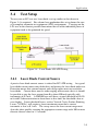
Test Setup
To carry out an LIV test on a laser diode a set up similar to that shown in
Figure 3-4 is required. For volume laser production this set up forms the core
of a complete automatic test equipment (ATE) environment. Carrying out the
LIV tests in the shortest possible time means that all of the individual pieces of
equipment need to be optimized for speed.
Figure 3-4
3.4.1
Laser Diode LIV ATE Testing
Laser Diode Current Source
A precise laser diode current source is critical for LIV ATE testing. Any good
laser diode current source must both drive and protect the laser diode under test.
Protection means that external current and voltage spikes must not reach the
laser diode. Current drive must be wide ranging and accurate, that is it should
be possible to step the laser current from 0 to about 500 mA typically with
increments of 0.5 mA. A DWDM laser will have a typical threshold of 10-30
mA with LI characterization to about three to five times the threshold value or
even higher. Lower threshold lasers, such as Vertical Cavity Surface Emitting
Lasers (VCSELs), will require a lower maximum current but a current
increment as low as 0.1 mA. The sweep across the laser current range must
also take place quickly covering the appropriate current range with 100 or more
discrete current values in 1-2 seconds.
3-5
Current Source/Measure Module 52956 User’s Manual
The current source must also be capable of measuring the forward voltage on
the laser accurately with milli-volt resolution, at a speed fast enough to track
source current changes.
3.4.2
Optical Power Meter
An optical power meter is needed to measure optical power levels. It may
also be used to facilitate the automatic alignment of a test fiber with the laser
diode output facet. Typically the power meter will need a wide dynamic range
from –70 dBm to +3 dBm or higher. A high speed LIV ATE setup demands
power meters capable of at least matching the incremental speed of the current
source typically taking measurements at intervals of 1 ms or less.
It is worth noting that in setting up an LIV ATE test any instrument induced
non-linearities may be misinterpreted as kinks, leading to false rejections of
lasers. For example many power meters utilize auto ranging, which is a useful
way of achieving a large dynamic range. However auto-ranging can lead to
small power steps at the range switch points which can be misinterpreted as
kinks. One approach is to force the power meter to remain on a fixed range if
possible, however this may not be possible where the power range exceeds two
decades.
3.4.3
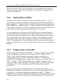
Temperature Controller
Precise temperature control is also needed. Lasers are temperature controlled
using a combination of a Peltier cooler element (a TEC, “Thermoelectric
Cooler”) and a feedback temperature monitor such as a thermistor or
semiconductor device. Control to within at least 0.05 °C is needed and
depending on the application the temperature test range may be from –10 °C to
+50 °C or wider. While absolute temperature stability is important, with
long-term stability values of ±0.01°C or better available, it is the overall speed
of response that is of most significance for LIV testing of laser diode at
manufacture.
Ideally a temperature controller should be able to bring a laser diode to a set
temperature as rapidly as possible but with a very fast settling time once the set
temperature is reached and this requires sophisticated control. The most
common form of control is a PID loop which derives is name from the presence
of Proportional Gain (P), Integration (I) and Differentiation (D), in the control
3-6
Application
loop. Typically the PID loop is implemented digitally to allow for ease of
programming. Programming allows the dynamic response of the controller to
be optimized by independently setting the gain, integration time and the
differential time constant.
PID control is superior form of control by comparison with a simple PI loop
control. This is because introducing the derivative term reduces the settling
time after a step change in temperature and thus reduces the overall
measurement time. PI based laser diode temperature controllers are only
adequate for applications where overall temperature response speed is not a
critical factor.
BFM Photodiode Measurements
An LIV ATE setup may also incorporate a means of measuring the BFM
photodiode voltage and output current. The current range required will
depend on the measurements to be carried out, but measurement up to 10 mA
or higher may be required. Measuring dark current on the other hand will
require sub-nA grade current measurement. It should also be remembered that
BFM photodiode dark current is strongly influenced by temperature, so that
such measurements may need to be repeated at several temperatures.
Given the wide dynamic range required for BFM photodiode current
measurement typically this is best carried out using an optical power meter
which allows for direct connection of the BFM. The reason for this is that
optical power meter front ends are designed from the outset to cater for very
low current levels in the pA range. Most conventional multi-meters are not
designed for this, with lowest ranges in the A region.
3.5
Dealing with Tunable Laser Diodes
The multi-section nature of these devices calls for an LIV ATE setup that
incorporates multiple current sources and can provide precise synchronization
between these sources. In these cases by definition the LIV scans are both
lengthy and complex. A four sections laser diode module may require many
10,000's of individual measurements in comparison to a few hundred for a
single section laser. Therefore a tunable laser LIV ATE setup should be able
to run at least 100K tests with precise timing between the various elements and
with storage for all the results in ‘Real Time’. It should also be capable of
transferring these results to the controlling computer in either single or block
form without causing the test process to slow.
3-7
Current Source/Measure Module 52956 User’s Manual
3.6
Multi-Head Test
As laser diode manufacturers seek to improve efficiency, the modern LIV ATE
structure should be easy to expand from a single laser test station to one that
can, for example, deal with four laser diodes at one time. Thus the LIV ATE
design needs to be scalable to suit present and future requirements. The
existing infrastructure should have enough capacity to house the additional
resources. It goes without saying that a 'single head' LIV ATE should occupy
very little space but also that the expansion to multiple heads should demand as
little extra space as possible. Space is always at a premium in these cases.
The Complete System
All of the elements above must be combined to function in a complete ATE
environment, which controls, retrieves and stores the data as quickly as
possible. PX Instrument Technology is developing a complete range of modules
for ATE based laser LIV testing based on the PXI standard. This range will
compliment the company’s existing broadband PXI-based optical switching
products.
PXI is a very beneficial platform for characterizing lasers as it offers high speed
and excellent synchronization facilities that allow all of the elements of an LIV
system to optimally function together.
3-8
Software
4.
Software
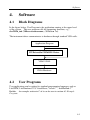
4.1
Block Diagrams
In the figure below, User Program is the application running at the upper level
of the system. The user program calls for supporting functions, e.g.…
chr52956_init (ViResc resourcename,..,ViSession *vi).
The instrument driver communicates to hardware through standard VISA calls.
Application Program
IVI Driver/chr52956.DLL Driver
VISA32.DLL
52956 Hardware
4.2
User Programs
User applications can be written by standard programming languages such as
LabVIEW, LabWindows/CVI, Visual Basic, Visual C++, and Borland C++
Builder. An example written in C of it can be seen in section 6.3 Example
Program.
4-1
Basic Operation
5.
Basic Operation
Chroma 52956 Current Source/Measure Module can be used as a simple device
for providing a current stimulus and/or voltage measurement, which is either
program controlled or manually controlled. It can also be used as a more
complex device, which automatically sequences through a range of stimuli or
measure or combined stimuli and measurement steps.
Once the module(s) is/are correctly installed, the user should have access to
functions which allow them to use the module(s).
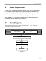
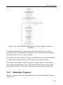
5.1
Block Diagrams
The following figure shows the device operation flow.
programs to control the instrument.
Application
Programming
Users need to use
GUI
Instrument Drivers
VISA
Device Drivers
Instrument
Figure 5-1
5-1
Current Source/Measure Module 52956 User’s Manual
5.2
Manual Mode
A Soft Front Panel program is provided which allows the user to manually
control all of Chroma 52956 modules which are installed in their system. The
SFP52956.exe is located in the directory specified during the installation
process (usually in C:\Program Files\Chroma\PXI\52956\ SFP52956.EXE).
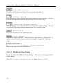
5.2.1
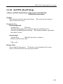
How to Use Soft Front Panel (SFP)
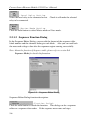
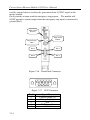
SFP will show the dialog to select a 52956 as follows.
Figure 5-2
Configuration Dialog
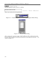
Choose a module as you need and click Open to enter main panel.
Instrument Resource
Descriptor
Menu Bar
Compliance Indicator
(Visible when compliance
occurs)
Output Range
indicator
Wire Mode
indicator
Output indicator
Current setting
indicator
Voltage meter
Current Limit
setting indicator
Voltage setting
indicator
Output Range
control
Compliance
voltage control
Reset button
Current control
Output button
Wire Mode
control
Figure 5-3
5-2
Status / Error
indicator
Main Panel
Basic Operation
Main Panel function description:
- Instrument Resource Descriptor
Indicate which instrument is currently be used.
- Menu Bar
Open module setting and sequence function dialog.
/
- Output indicator
The symbol
means output ON, and
means output OFF.
- Current setting indicator
Indicate the actual current value that has been set.
- Voltage meter
The voltage measurement value of the UUT.
- Current Limit setting indicator
Indicate the current limit setting value. Current Limit can be set in the
Module Setting dialog.
- Voltage setting indicator
Indicate the compliance voltage setting value.
- Wire Mode indicator
Indicate the wire mode setting.
is 2 wire mode, and
is 4 wire mode.
- Output Range indicator
Indicate currently range select.
is 0 ~ 500mA, and
is 0 ~ 50mA.
- Compliance Indicator
Indicate if the compliance condition is occurred.
Note: The symbol is visible only if the compliance condition is occurred, or it is
invisible.
- Output Range control
Click the radio button can change the output range immediately.
Note: The Output Range Control will be disabled when the output is ON.
5-3
Current Source/Measure Module 52956 User’s Manual
- Wire Mode control
Click the radio button can change the wire mode immediately.
- Current control
Edit the current value and click Enter can change the current setting.
can click the increment and decrement button to set current value.
Or you
- Compliance voltage control
Edit the voltage value and click Enter can change the voltage setting.
can click the increment and decrement button to set voltage value.
Or you
- Reset button
Reset the instrument to the initialized state.
- Output button
Control the output ON/OFF. When the label of the button is “Output ON”, it
means you can click the button to make the module “output ON”, and vice
versa.
- Status / Error Indicator
Show error code and its description here.
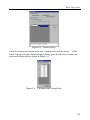
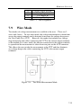
5.2.1.1 Module Setting Dialog
Figure 5-4 shows the Module Setting Dialog.
on this dialog.
You can set several parameters
Note: Every setting is changed only when the Apply button is clicked.
5-4
Basic Operation
Figure 5-4
Module Setting Dialog
Module Setting Dialog function description:
- Current Limit setting
Modify the current limit value. After clicking Apply, the range of the current
value you can set in the main panel cannot exceed this value.
- Enable Hardware Trigger
Check it to make hardware trigger enabled. Uncheck it to make hardware
trigger disabled.
Select the trigger setup.
- Trigger Setup Selection
Possible selections are listed below:
Setup
TRIG None
TRIG0 IN
TRIG1 IN
TRIG2 IN
TRIG7 IN
TRIG0 OUT
TRIG1 OUT
TRIG2 OUT
TRIG7 OUT
Purpose
None
For Slave
For Master
- Measure Average Setting
Select the measure average times that the instrument used in every voltage
measurement. It can only be 1, 2, 4, 8, 16, 32, 64 or 128. For example, if 32
has been chosen, the instrument will take 32 measurements then return the
averaged value.
5-5
Current Source/Measure Module 52956 User’s Manual
- Local Relay Setting
Select the local relay to be connected or not.
relay to be connected.
Check it will make the selected
- Master Mode Setting
Click the radio button to select Master mode or Slave mode.
5.2.1.2 Sequence Function Dialog
In the Sequence Editor Dialog, you can edit the format of the sequence table,
block number and the elements belong to each block. Also you can read back
the measured voltage value after the sequence engine running successfully.
Note: About the function of Sequence table, please refer to section 5.4
Sequence Mode for detailed information.
Figure 5-5
Sequence Editor Dialog
Sequence Editor Dialog function description:
- Function Switch
Click the radio button to switch the function. This dialog can be a sequence
editor or a sequence data reader. If the sequence never runs and stops
5-6
Basic Operation
successfully since this program starts, the Retrieve Data option will be
disabled.
- The Number of Blocks
Change the number of blocks in the sequence table. You can enter the block
number then click “Enter”, or just click the increment or decrement arrows to
change the number. Once the number is changed, the grid will increase or
decrease its size. You can key-in the element count, source delay time and
measure delay time of each block.
- Sequence Behavior Selection
The sequence has three behavior types. Source only, measure only and both.
Check the behaviors you want here.
- Sequence Control and Status
Click Run Master (Run Slave) button to start the sequence engine. The
status of sequence engine will be shown here. The status description listed
below:
1.
2.
3.
– It means the sequence engine is completed.
– It means the sequence engine is running.
– It means the sequence engine is stopped with
some error occurred.
- The Grid Editor
Each row represents a block and possesses columns to key-in block information.
As shown in Figure 5-6, when clicking the right mouse button in the row, a
popup menu will be shown. Select Edit block will open an element edit
dialog. The Element Editor Dialog is shown in Figure 5-7.
- Apply Button
After finishing edit sequence table, you can click Apply button to write it into
instrument, and the Run Master (Run Slave) button will be enabled.
- Close Button
Click close button will close the sequence editor dialog. Everything will be
stored until the program is closed. So you still can continuously edit the
sequence table when the sequence edit dialog is opened again.
5-7
Current Source/Measure Module 52956 User’s Manual
- Stop Button
Stop the sequence engine when it is running.
Show error code and its description here.
Figure 5-6
- Status / Error Indicator
Click the Right Mouse Button in the Sequence Editor Dialog
Figure 5-7
Element Editor Dialog
After running the sequence engine, click the Retrieve Data radio button in the
Function Switch group can turn the edit grid into read sequence data grid. It is
shown in Figure 5-8.
5-8
Basic Operation
Figure 5-8
Retrieve Data
Click the right mouse button in the row, a popup menu will be shown. Select
Show Voltage will open Element Editor dialog again, but this time it shows the
measured voltage data as shown in Figure 5-9.
Figure 5-9
The Measured Voltage Data
5-9
Current Source/Measure Module 52956 User’s Manual
5.3
Computer Controlled – Simple
Automation
It is possible for the user to develop applications to provide simple automation
to the Chroma 52956 module(s). Using this method, commands are sent from
the system PC controller via the PCI bus to the target module and which are
instantly executed by the target module. Using this method, the user can
enable the output, change output settings such as current range, value, etc.
However, timing is computer and bus dependent and timing between output
settings is difficult to guarantee.
5.4
Sequence Mode
In Sequence Mode, the user loads the memory of Chroma 52956 module with a
pre-defined table containing a series of output setting values and configuration
settings. When the sequencer is run, it steps through each element of the table
and performs an action depending on the configuration setting of the FORMAT
byte. The FORMAT byte is the fourth byte of the table and sets up the
module as a measure module only, a source module only or a combined source
/measure module.
The operation of the sequence while running is totally independent of the
system controller and therefore timing restrictions of the PCI bus and System
controller are not applicable.
Once the sequence has completed, the contents of the table in the module
memory can be uploaded to a file on the System PC and its contents analyzed.
One or more modules using the sequencer functionality may run synchronously.
Section 4 of this manual explains some of the theory of the operation of the
sequencer. However, there are some setup considerations which must be
taken into account before implementing this.
When two or more modules are used as part of a sequence group, they
must be immediately adjacent to each other. There can be NO empty
slots between modules in the same sequence group.
One of the modules must be designated to run in master mode and the
remainder to run in slave mode.
5-10
Basic Operation
If the group of modules span over two or more PCI bus segments, the
trigger bus bridge must be switched on to drive the trigger bus signal in
the correct direction.
Each module in the group must use the same trigger bus line.
The group must be linked together using the left & right Local Bus relays
as appropriate.
If more than one sequence group is used on a system bus, different trigger
bus lines must be used for each sequence group.
If the different sequence groups are immediately adjacent to each other,
the local bus relays between the adjacent modules in the two groups must
be disconnected.
5.4.1
Overview
Sequencing on the Chroma Photonic range of modules which support HSIS
functionality consists of a number of PXI modules, all linked via PXI
synchronization lines, one module operating as a master with all other modules
operating as slaves
Some modules may operate as single or dual source instruments, some may
operate as single or dual measure instruments and some may operate as a
combination of both.
Each sequence step will usually consist of a source function or a measure
function, however it is possible for some modules to perform a source and a
measure function or even two measure functions within a single sequence step.
The functionality of a module is defined using the FORMAT byte parameter,
which is stored in the sequence header block. While a module may be able to
perform both source and measure functions, the format parameter defines
which are used during the sequence.
Because all the sequence modules are synchronized at step level, the number of
functions performed during a sequence step should be identical throughout all
modules. For example, if one module is performing two measurements per
step, and one module is only performing one source per step, the module
performing the source function should include an additional function, usually a
NULL function. This will aid debug, and clarify the memory data.
Although it would be typical to run a number of modules in a sequence group, a
single module can also perform a sequence. In this instance, the module
5-11
Current Source/Measure Module 52956 User’s Manual
would be configured as the master and would not require the use of the
synchronizing signals.
The complete sequence table loaded into a modules memory is broken down
into a number of blocks, each with its own timing characteristics, and each able
to have up to 216 steps.
Each block would be used to hold similar sequence steps, all having a common
timing requirement, therefore a typical sequence might require one block for
executing six sequence steps of 1mS, one block for executing a single step of
10mS, followed by an additional block of 1mS steps
This single step block in this example would allow a discharge or settle to be
introduced.
The RAM is accessed in a sequential manner using only the commands
sequence reset and sequence read and write which auto increment the address
counter. Therefore the address counter on each module MUST BE reset prior to
the upload of data, the running of a sequence or the download of data
Sequencing on Chroma 52956 is achieved by executing a pre-defined number
of “blocks” contained within the on board RAM. Each “block” contains
group timing information and depending on the module function, a number of
source or measurement data, each referred to as an element.
The requirement for individual delays will ultimately determine the number of
blocks required. It is only when a delay changes that a new block is required.
The option exists of course to break up output patterns into smaller manageable
chunks
A typical example is one where three different data patterns are required, each
one being spaced by a single element block, which ensures that the current
settles to a stable value before the next ramp starts. The individual ramps can
have any number of steps, and providing all require the same timing, can be
placed in the same block.
5-12
Basic Operation
Block #
1
2
3
4
5
6
7
8
Element #
1
250
1
1000
1
20000
20000
1
Table 5-1
Function
Set output to 5mA
Set a Pattern-1 250 values
Set an O/P of 0mA
Set a Pattern-2 250 values
Set an O/P of 0mA
Set a Pattern-3 20000 values
Set a Pattern-4 20000 values
Set an O/P of 0mA
Timing per step
10mS
1mS
5mS
50uS
5mS
1mS
2mS
10mS
Example of Data Table Block Overview
The output from the data given in the above table would be as follows:
10mS at 5mA, 250mS of Pattern-1, 5mS at 0mA, 50mS of Pattern-2, 5mS at
0mA, 20 seconds of Pattern-3, 40 seconds of Pattern-4, and finally 10mS of
0mA.
A sequence is therefore performed by:
1. Uploading some data
2. Configuring the module
3. Running the sequence
4. Waiting for sequence completion
5. Downloading the data
5.4.2
Data Table Creation and Upload
The data table that is loaded into the module(s) memory can be created from a
user program or extracted from a file. Method of data table creation is left up
to the user. One method is to create a CONFIG.DAT file, which initializes
the system and configures all modules. Before any data may be written, the
sequence must be reset using the call:
chr52956_SequenceReset()
5.4.2.1 The Block Header
The block header defines how many elements exist within the block, what
timing is used for both the source and the measure cycle, and a specific control
word unique to each module.
5-13
Current Source/Measure Module 52956 User’s Manual
The block header is read and written using the calls:
ViStatus _VI_FUNC chr52956_SequenceWriteBlockHeader (ViSession vi,
ViUInt16 count, ViUInt16 sourceDelay, ViUInt16 measureDelay);
ViStatus _VI_FUNC chr52956_SequenceReadBlockHeader (ViSession vi,
ViUInt16 *count, ViUInt16 *sourceDelay, ViUInt16 *measureDelay);
5.4.2.2 The Block Data
The block data consists of the individual sequence elements, each of which is
defined by the data format word. i.e. if the format specifies both source and
measure functionality, the single element will consist of both a source value
and a measure value. If the format specifies only a source function, the single
element will consist of only a single source value
The actual data stored in the block is in the form of signed 16 bit integers
suitable for the on board DACs, and ADC’s, however data is passed as either
ViReal64 “double” format or ViUInt16 “unsigned integer” format.
The block data is read and written using the calls:
ViStatus _VI_FUNC chr52956_SequenceWriteBlockData (ViSession vi,
ViUInt16 count, chr52956SequenceData *sequenceData, ViUInt16 format);
ViStatus _VI_FUNC chr52956_SequenceReadBlockData (ViSession vi,
ViUInt16 count, chr52956SequenceData *sequenceData, ViUInt16 format);
Data is passed to and from the functions as a group of arrays of either
ViReal64’s or ViUInt16’s. A specific data structure of the type
chr52956SequenceData is used for this data transfer and consists of four
pointers, source1, source2, measure1, and measure2.
Either an array of values can be created, with this array address being assigned
to the relevant pointer, or a heap block can be directly allocated to the pointer.
Any unused pointers must be set to NULL or 0, to declare them as unused.
These arrays along with the data format bytes are used by the two functions for
data transfer. It is important that the format byte used in the header block
function matches that of the format byte used by the block data function.
5-14
Basic Operation
Figure 5-10
Block Diagram Showing Typical Steps Required to Load a
Sequence
It should be noted that due to the way in which the sequencer runs, the first
item of measure is performed before the first item is sourced, thereby causing a
NULL measure item at the start of a block.
In a similar way, the last item of source is performed after the last measurement
has taken place, thereby causing a NULL source at the end of a block.
This source can be used by either the previous source value or a zero value, or
the next blocks initial source value. The initial NULL measure value of the
next block will in fact use the final NULL source value of the previous block.
5.4.3
Running a Sequence
Before a sequence can be run, the module must be configured and the sequence
engine reset.
5-15
Current Source/Measure Module 52956 User’s Manual
Configuration would consist of setting either 2 wire mode or 4 wire mode,
enabling current outputs, as well as connecting the synchronizing signals
(Local and Trigger bus) between adjacent boards and setting up the module for
external IO (via AUX connector) or internal IO triggered.
The sequence is started using the chr52956_SequenceRunSlave() and
chr52956_SequencRunMaster() calls. The ‘Run Slave’ call should always be
sent to all slave modules in a group before the ‘Run Master’ call is used. If
there is only one module in a group, the ‘Run Slave’ call is not required.
Once the Run Master command is sent, the sequence will commence. Only
the synchronizing lines are able to externally control the master, hence why the
slaves are started first.
If the inter-module links (Local bus and Trigger bus routing) are not made,
nothing will externally stop the master module, and it will promptly finish its
sequence without regard for any other boards. The sequencer is executed
using the calls:
ViStatus _VI_FUNC chr52956_SequenceRunMaster (ViSession vi);
ViStatus _VI_FUNC chr52956_SequenceRunSlave (ViSession vi);
There is no status signal sent to the system controller from the modules to let it
know if the sequence is completed, however once the sequence has completed
one of two bits will be set in the status register. One is for sequence done, one
for sequence error.
By polling this bit, the user can find out if the sequence has completed
successfully or if an error has occurred. If all the modules were set up
correctly, every module in the sequence will enable its complete bit, otherwise
there is an error within the sequence data or module setup.
5.4.4
Downloading the Results Data Table
Before any data can be downloaded from the modules, the sequence must be
reset using the call chr52956_SequenceReset().
The data stored in the block is in the form of signed 16 bit integers suitable for
the on board ADC’s, and is passed as either ViReal64 “double” format or
ViUInt16 “unsigned integer” format.
5-16
Basic Operation
The block data is read using the calls:
ViStatus _VI_FUNC chr52956_SequenceReadBlockData (ViSession vi,
ViUInt16 count, chr52956SequenceData *sequenceData, ViUInt16 format);
Figure 5-11
5.4.5
Block Diagram Showing Typical Download Steps
Types of Sequence
Although the sequence scans through a single table containing blocks of data
on a module, it is possible to use the sequence to perform specific functions.
5.4.5.1 Single Sweep
This is used where a module or modules each run through a single sequence of
outputting to function. This is the simplest way to use the modules.
5-17
Current Source/Measure Module 52956 User’s Manual
5.4.5.2 Raster Scan
Used primarily for driving tunable laser diodes, each current source pattern is
driven inside of another current source pattern, effectively forming a nested
loop.
For example the inner loop might be stepped through a sequence of 10 currents,
whereby the next inner loop would be indexed, and once again another 10
currents would be performed.
MODULE1
BLOCK1 ELEMENT
1
2
3
4
5
6
7
8
9
10
BLOCK2 ELEMENT
1
2
3
4
5
6
7
8
9
10
BLOCK3 ELEMENT
1
2
3
4
5
6
7
8
9
10
Table 5-2
DATA
1.005
1.010
1.015
1.020
1.025
1.030
1.035
1.040
1.045
1.050
DATA
1.005
1.010
1.015
1.020
1.025
1.030
1.035
1.040
1.045
1.050
DATA
1.005
1.010
1.015
1.020
1.025
1.030
1.035
1.040
1.045
1.050
MODULE2
BLOCK1 ELEMENT
1
2
3
4
5
6
7
8
9
10
BLOCK2 ELEMENT
1
2
3
4
5
6
7
8
9
10
BLOCK3 ELEMENT
1
2
3
4
5
6
7
8
9
10
DATA
1.005
1.005
1.005
1.005
1.005
1.005
1.005
1.005
1.005
1.005
DATA
1.010
1.010
1.010
1.010
1.010
1.010
1.010
1.010
1.010
1.010
DATA
1.015
1.015
1.015
1.015
1.015
1.015
1.015
1.015
1.015
1.015
Example Showing Three Blocks of a 10 Blocks Raster Scan Table
This type of sequence may require many delay blocks to be inserted after each
loop, to allow the current to settle. This will depend on the application.
5-18
Basic Operation
5.4.6
Data Formats on the Sequencer
The High Speed Instrument Sequencer (HSIS) is designed to be adaptable for
use with various instrument configurations, and is suitable for using with a
range of Chroma’s instrument modules with HSIS functionality.
For each step of the sequencer, compatible PXI modules can perform one or
two source operations, one or two measure operations, one source and one
measure operation, or one or two NULL operations. The NULL is this case
meaning perform no operation. NULL operations are provided for instances
where users are using multiple PXI HSIS modules and a module or module
channel may be required not to do anything while other modules are
performing.
Before running a sequence, each module must have its mode of operation
configured. This is achieved by setting bits in a control mode FORMAT byte.
Each bit represents a mode of operation and if set, the module will perform the
mode of I/O operation if it is capable of it. The FORMAT byte is the fourth
byte of the sequence table.
Although the FORMAT byte has 6 settable bits, only the first three bits are
used with Chroma 52956 modules. Only a maximum of two bits should be set
at any time. The other bits should be set to zero.
Figure 5-12
Sequence Table Showing Format Byte
5-19
Current Source/Measure Module 52956 User’s Manual
Each bit set will reserve two bytes memory allocation for each sequence step.
Each module in the same sequence group with HSIS functionality must use the
same number of bytes as the sequence tables loaded into each module must be
identical in element positioning. If there is a mismatch between modules of
the same group, the sequence will not run correctly and cause un-expected
results or an exception error.
Figure 5-13
FORMAT Byte
Example:
An application requires one Chroma 52956 Current Source/Measure Module to
supply current. No measurements are required. A second PXI module is
connected which has two types of function. Therefore, although Chroma
52956 does not require four bytes in each element, it must use four bytes so that
its table matches the table structure in the other module. The binary word
00000101 or Hex 0x05 would be written to the FORMAT byte of the module’s
table.
Figure 5-14
5-20
FORMAT Byte Used in above Example
DLL Calls and Example Programs
6.
DLL Calls and Example
Programs
6.1
DLL Calls
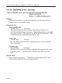
6.1.1
chr52956_init
ViStatus chr52956_init (ViRsrc resourceName,
ViBoolean IDQuery,
ViBoolean resetDevice,
ViPSession instrumentHandle);
Purpose
This function performs the following initialization actions:
- Creates a new IVI instrument driver session.
- Opens a session to the specified device using the interface and address
you specify for the Resource Name parameter.
- If the ID Query parameter is set to VI_TRUE, this function queries the
instrument ID and checks that it is valid for this instrument driver.
- If the Reset parameter is set to VI_TRUE, this function resets the
instrument to a known state.
- Sends initialization commands to set the instrument to the state necessary
for the operation of the instrument driver.
- Returns a ViSession handle that you use to identify the instrument in all
subsequent instrument driver function calls.
Note: This function creates a new session each time you invoke it.
Although you can open more than one IVI session for the same
resource, it is best not to do so. You can use the same session in
multiple program threads. You can use the chr52956_LockSession
and chr52956_UnlockSession functions to protect sections of code
that require exclusive access to the resource.
Parameter List
resourceName
Variable Type
ViRsrc
Pass the resource name of the device to initialize.
6-1
Current Source/Measure Module 52956 User’s Manual
You can also pass the name of a virtual instrument or logical name that
you configure with the IVI Configuration utility. The virtual instrument
identifies a specific device and specifies the initial settings for the session.
A logical Name identifies a particular virtual instrument.
IDQuery
Variable Type
ViBoolean
Specify whether you want the instrument driver to perform Cn ID Query.
Valid Range:
VI_TRUE (1) - Perform ID Query (Default Value)
VI_FALSE (0) - Skip ID Query
resetDevice
Variable Type
ViBoolean
Specify whether you want to reset the instrument during the initialization
procedure.
Valid Range:
VI_TRUE (1) - Reset Device (Default Value)
VI_FALSE (0) - Don't Reset
instrumentHandle
Variable Type
ViSession (passed by reference)
Returns a ViSession handle that you use to identify the instrument in all
subsequent instrument driver function calls.
Notes:
(1) This function creates a new session each time you invoke it. This is
useful if you have multiple physical instances of the same type of
instrument.
(2) Avoid creating multiple concurrent sessions to the same physical
instrument. Although you can create more than one IVI session for
the same resource, it is best not to do so. A better approach is to use
the same IVI session in multiple execution threads. You can use
functions chr52956_LockSession and chr52956_UnlockSession to
protect sections of code that require exclusive access to the resource.
Return Value
Status code 0 is for success. To obtain a text description of the status
code, call the chr52956_error_message function.
6-2
DLL Calls and Example Programs
6.1.2
chr52956_InitWithOptions
ViStatus chr52956_InitWithOptions (ViRsrc resourceName,
ViBoolean IDQuery,
ViBoolean resetDevice,
ViString optionString,
ViPSession instrumentHandle);
Purpose
This function performs the following initialization actions:
- Creates a new IVI instrument driver and optionally sets the initial state of
the following session attributes:
CHR52956_ATTR_RANGE_CHECK
CHR52956_ATTR_QUERY_INSTR_STATUS
CHR52956_ATTR_CACHE
CHR52956_ATTR_SIMULATE
CHR52956_ATTR_RECORD_COERCIONS
- Opens a session to the specified device using the interface and address you
specify for the Resource Name parameter.
- If the ID Query parameter set to VI_TRUE, this function queries the
instrument ID and checks that it is valid for this instrument driver.
- If the Reset parameter set to VI_TRUE, this function resets the instrument
to a known state.
- Sends initialization commands to set the instrument to the state necessary
for the operation of the instrument driver.
- Returns a ViSession handle that you use to identify the instrument in all
subsequent instrument driver function calls.
Note: This function creates a new session each time you invoke it.
Although you can open more than one IVI session for the same
resource, it is best not to do so. You can use the same session in
multiple program threads. You can use the chr52956_LockSession
and chr52956_UnlockSession functions to protect sections of code that
require exclusive access to the resource.
Parameter List
resourceName
Variable Type
ViRsrc
Pass the resource name of the device to initialize.
You can also pass the name of a virtual instrument or logical name that
you configure with the IVI Configuration utility. The virtual instrument
identifies a specific device and specifies the initial settings for the session.
A logical Name identifies a particular virtual instrument.
6-3
Current Source/Measure Module 52956 User’s Manual
IDQuery
Variable Type
ViBoolean
Specify whether you want the instrument driver to perform ID Query.
Valid Range:
VI_TRUE (1) - Perform ID Query (Default Value)
VI_FALSE (0) - Skip ID Query
resetDevice
Variable Type
ViBoolean
Specify whether you want the to reset the instrument during the
initialization procedure.
Valid Range:
VI_TRUE (1) - Reset Device (Default Value)
VI_FALSE (0) - Don't Reset
optionString
Variable Type
ViString
You can use this control to set the initial value of certain attributes for the
session. The following table lists the attributes and the name you use in
this parameter to identify the attribute.
Name
--------------------RangeCheck
QueryInstrStatus
Cache
Simulate
RecordCoercions
Attribute Defined Constant
-------------------------------------------------------CHR52956_ATTR_RANGE_CHECK
CHR52956_ATTR_QUERY_INSTR_STATUS
CHR52956_ATTR_CACHE
CHR52956_ATTR_SIMULATE
CHR52956_ATTR_RECORD_COERCIONS
The format of this string is, "AttributeName=Value" where AttributeName
is the name of the attribute and Value is the value to which the attribute
will be set. To set multiple attributes, separate their assignments with a
comma.
If you pass NULL or an empty string for this parameter and a VISA
resource descriptor for the Resource Name parameter, the session uses the
default values for the attributes. The default values for the attributes are
shown below:
6-4
DLL Calls and Example Programs
Attribute Name
------------------RangeCheck
QueryInstrStatus
Cache
Simulate
RecordCoercions
Default Value
----------------VI_TRUE
VI_TRUE
VI_TRUE
VI_FALSE
VI_FALSE
You can override the values of the attributes by assigning a value explicitly
in a string you pass for this parameter. You do not have to specify all of the
attributes and may leave any of them out. If you do not specify one of the
attributes, its default value or the value that you configure with the IVI
Configuration utility will be used.
The following are the valid values for ViBoolean attributes:
True:
1, TRUE, or VI_TRUE
False:
0, False, or VI_FALSE
Default Value:
"Simulate=0,RangeCheck=1,QueryInstrStatus=1,Cache=1"
instrumentHandle
Variable Type
ViSession (passed by reference)
Returns a ViSession handle that you use to identify the instrument in all
subsequent instrument driver function calls.
Notes:
(1) This function creates a new session each time you invoke it. This is
useful if you have multiple physical instances of the same type of
instrument.
(2) Avoid creating multiple concurrent sessions to the same physical
instrument. Although you can create more than one IVI session for
the same resource, it is best not to do so. A better approach is to use
the same IVI session in multiple execution threads. You can use
functions chr52956_LockSession and chr52956_UnlockSession to
protect sections of code that require exclusive access to the resource.
Return Value
Status code 0 is for success. To obtain a text description of the status
code, call the chr52956_error_message function.
6-5
Current Source/Measure Module 52956 User’s Manual
6.1.3
chr52956_close
ViStatus chr52956_close (ViSession instrumentHandle);
Purpose
This function performs the following operations:
- Closes the instrument I/O session.
- Destroys the instrument driver session and all of its attributes.
- Deallocates any memory resources the driver uses.
Notes:
(1) You must unlock the session before calling chr52956_close.
(2) After calling chr52956_close, you cannot use the instrument driver
again until you call chr52956_init or chr52956_InitWithOptions.
Parameter List
instrumentHandle
Variable Type
ViSession
The ViSession handle that you obtain from the chr52956_init or
chr52956_InitWithOptions function. The handle identifies a particular
instrument session.
Return Value
Status code 0 is for success. To obtain a text description of the status
code, call the chr52956_error_message function.
6-6
DLL Calls and Example Programs
6.1.4
chr52956_SetComplianceVoltage
ViStatus chr52956_SetComplianceVoltage (ViSession instrumentHandle,
ViReal64 voltage);
Purpose
This function sets the compliance voltage value in volts.
Parameter List
instrumentHandle
Variable Type
ViSession
The ViSession handle that you obtain from the chr52956_init or
chr52956_InitWithOptions function. The handle identifies a particular
instrument session.
voltage
Variable Type
ViReal64
The voltage value in volts.
Unit : Volt
Valid Value: 0V to 8V.
Return Value
Status code 0 is for success. To obtain a text description of the status
code, call the chr52956_error_message function.
6-7
Current Source/Measure Module 52956 User’s Manual
6.1.5
chr52956_SetCurrent
ViStatus chr52956_SetCurrent (ViSession instrumentHandle,
ViReal64 current);
Purpose
This function sets the output current value of the module.
Parameter List
instrumentHandle
Variable Type
ViSession
The ViSession handle that you obtain from the chr52956_init or
chr52956_InitWithOptions function. The handle identifies a particular
instrument session.
current
Variable Type
ViReal64
The output current of the module. According to different output range,
the output current is range from 0mA to 500mA.
Unit : mA
Valid Value : 0 to 50mA (0 to 50mA current range)
0 to 500mA (0 to 500mA current range)
Return Value
Status code 0 is for success. To obtain a text description of the status
code, call the chr52956_error_message function.
6-8
DLL Calls and Example Programs
6.1.6
chr52956_SetWireMode
ViStatus chr52956_SetWireMode (ViSession instrumentHandle,
ViUInt16 wireMode);
Purpose
This function determines whether the voltage reading is internal (2 wire),
or external (4 wire). 2 wire is used for measuring the source voltage on
the current output. 4 wire is used for measuring the actual voltage on the
current source or another voltage source.
Parameter List
instrumentHandle
Variable Type
ViSession
The ViSession handle that you obtain from the chr52956_init or
chr52956_InitWithOptions function. The handle identifies a particular
instrument session.
wireMode
Variable Type
ViUInt16
The wire mode is to set the instrument.
Valid Value : 2-wire (0) CHR52956_VAL_2W - Default value
4-wire (1) CHR52956_VAL_4W
Return Value
Status code 0 is for success. To obtain a text description of the status
code, call the chr52956_error_message function.
6-9
Current Source/Measure Module 52956 User’s Manual
6.1.7
chr52956_SetOutputRange
ViStatus chr52956_SetOutputRange (ViSession instrumentHandle,
ViUInt16 range);
Purpose
This function configures the current output range. By default a 0 to
500mA range is provided. However a 0 to 50mA range can be selected
giving finer current resolution.
Parameter List
instrumentHandle
Variable Type
ViSession
The ViSession handle that you obtain from the chr52956_init or
chr52956_InitWithOptions function. The handle identifies a particular
instrument session.
range
Variable Type
ViUInt16
The current output range.
Valid Value : (0) CHR52956_VAL_500mA - Default value
(1) CHR52956_VAL_50mA
Return Value
Status code 0 is for success. To obtain a text description of the status
code, call the chr52956_error_message function.
6-10
DLL Calls and Example Programs
6.1.8
chr52956_ConnectOutput
ViStatus chr52956_ConnectOutput (ViSession instrumentHandle);
Purpose
This function enables the output relay to make the current source module
start to generate output. It will let current be zero. Then connect output
relay.
Parameter List
instrumentHandle
Variable Type
ViSession
The ViSession handle that you obtain from the chr52956_init or
chr52956_InitWithOptions function. The handle identifies a particular
instrument session.
Return Value
Status code 0 is for success. To obtain a text description of the status
code, call the chr52956_error_message function.
6-11
Current Source/Measure Module 52956 User’s Manual
6.1.9
chr52956_DisonnectOutput
ViStatus chr52956_DisonnectOutput (ViSession instrumentHandle);
Purpose
This function disables the output relay preventing the current source
module from driving current. It will let current be zero. Then disconnect
output relay.
Parameter List
instrumentHandle
Variable Type
ViSession
The ViSession handle that you obtain from the chr52956_init or
chr52956_InitWithOptions function. The handle identifies a particular
instrument session.
Return Value
Status code 0 is for success. To obtain a text description of the status
code, call the chr52956_error_message function.
6-12
DLL Calls and Example Programs
6.1.10 chr52956_SetMeasureAverage
ViStatus chr52956_SetMeasureAverage (ViSession instrumentHandle,
ViUInt16 measureAverage);
Purpose
This function sets the measure average.
Parameter List
instrumentHandle
Variable Type
ViSession
The ViSession handle that you obtain from the chr52956_init or
chr52956_InitWithOptions function. The handle identifies a particular
instrument session.
measureAverage
Variable Type
ViUInt16
The measure average. It should be power of 2.
Valid Value: 0, 1, 2, 4, 8, 16, 32, 64, 128
Return Value
Status code 0 is for success. To obtain a text description of the status
code, call the chr52956_error_message function.
6-13
Current Source/Measure Module 52956 User’s Manual
6.1.11 chr52956_SetTriggerSetup
ViStatus chr52956_SetTriggerSetup (ViSession instrumentHandle,
ViUInt16 trigger);
Purpose
This function enables the specific trigger bus channel(s) which the
sequencing engine can use.
Parameter List
instrumentHandle
Variable Type
ViSession
The ViSession handle that you obtain from the chr52956_init or
chr52956_InitWithOptions function. The handle identifies a particular
instrument session.
trigger
Variable Type
ViUInt16
The trigger to be set.
Valid Value: (0x00) CHR52956_VAL_TRIG_NONE
(0x01) CHR52956_VAL_TRIG0_IN
(0x02) CHR52956_VAL_TRIG1_IN
(0x04) CHR52956_VAL_TRIG2_IN
(0x08) CHR52956_VAL_TRIG7_IN
(0x10) CHR52956_VAL_TRIG0_OUT
(0x20) CHR52956_VAL_TRIG1_OUT
(0x40) CHR52956_VAL_TRIG2_OUT
(0x80) CHR52956_VAL_TRIG7_OUT
Return Value
Status code 0 is for success. To obtain a text description of the status
code, call the chr52956_error_message function.
6-14
DLL Calls and Example Programs
6.1.12 chr52956_SetMasterMode
ViStatus chr52956_SetMasterMode (ViSession instrumentHandle,
ViUInt16 mode);
Purpose
This function enables the sequencing engine to drive I_SYNC rather than
receive it, and therefore control other slave boards.
Parameter List
instrumentHandle
Variable Type
ViSession
The ViSession handle that you obtain from the chr52956_init or
chr52956_InitWithOptions function. The handle identifies a particular
instrument session.
mode
Variable Type
ViUInt16
The mode of the instrument. The Master mode means the instrument is
capable to generate I_SYNC while the Slave mode means the instrument
is capable to receive I_SYNC.
Valid Value: (0) CHR52956_VAL_SLAVE - Default value
(1) CHR52956_VAL_MASTER
Return Value
Status code 0 is for success. To obtain a text description of the status
code, call the chr52956_error_message function.
6-15
Current Source/Measure Module 52956 User’s Manual
6.1.13 chr52956_SetLocalRelay
ViStatus chr52956_SetLocalRelay (ViSession instrumentHandle,
ViUInt16 relay);
Purpose
This function controls the local relays used to connect the adjacent left and
right modules. Both S_RDY and M_RDY are connected.
Parameter List
instrumentHandle
Variable Type
ViSession
The ViSession handle that you obtain from the chr52956_init or
chr52956_InitWithOptions function. The handle identifies a particular
instrument session.
relay
Variable Type
ViUInt16
The relay is connected or disconnected.
Valid Value: (0) Both relay OFF
- Default value
(1) CHR52956_VAL_LEFT_RELAY
(2) CHR52956_VAL_RIGHT_RELAY
(3) Both relay ON
Return Value
Status code 0 is for success. To obtain a text description of the status
code, call the chr52956_error_message function.
6-16
DLL Calls and Example Programs
6.1.14 chr52956_SetHWTriggerMode
ViStatus chr52956_SetHWTriggerMode (ViSession instrumentHandle,
ViBoolean enabled);
Purpose
This function allows the sequencing engine to use external triggers such as
the I/O stage ready signals, and external user triggers. It also allows the
hardware stabilization duration to be set, which controls when the H/W
trigger is used by the sequencing engine.
Parameter List
instrumentHandle
Variable Type
ViSession
The ViSession handle that you obtain from the chr52956_init or
chr52956_InitWithOptions function. The handle identifies a particular
instrument session.
enabled
Variable Type
ViBoolean
Enable hardware trigger or not.
Valid Value : VI_TRUE Enabled
VI_FALSE Disabled
Return Value
Status code 0 is for success. To obtain a text description of the status
code, call the chr52956_error_message function.
6-17
Current Source/Measure Module 52956 User’s Manual
6.1.15 chr52956_SetMaximumCurrent
ViStatus chr52956_SetMaximumCurrent (ViSession instrumentHandle,
ViReal32 maxCurrent);
Purpose
This function sets the maximum current of the instrument. The maximum
current is used to limit the maximum current value that user can set.
Parameter List
instrumentHandle
Variable Type
ViSession
The ViSession handle that you obtain from the chr52956_init or
chr52956_InitWithOptions function. The handle identifies a particular
instrument session.
maxCurrent
Variable Type
ViReal32
The maximum current value to be set.
Unit : mA
Valid Value : 0 to 50mA (0 to 50mA output range)
0 to 500mA (0 to 500mA output range)
Return Value
Status code 0 is for success. To obtain a text description of the status
code, call the chr52956_error_message function.
6-18
DLL Calls and Example Programs
6.1.16 chr52956_ReadMaximumCurrent
ViStatus chr52956_ReadMaximumCurrent (ViSession instrumentHandle,
ViPReal32 value);
Purpose
This function reads the maximum current from the instrument. The
maximum current is used to limit the maximum current value that user can
set.
Parameter List
instrumentHandle
Variable Type
ViSession
The ViSession handle that you obtain from the chr52956_init or
chr52956_InitWithOptions function. The handle identifies a particular
instrument session.
value
Variable Type
ViReal32 (passed by reference)
The maximum current value read from the instrument.
Unit: mA
Return Value
Status code 0 is for success. To obtain a text description of the status
code, call the chr52956_error_message function.
6-19
Current Source/Measure Module 52956 User’s Manual
6.1.17 chr52956_GetRelayThresholds
ViStatus chr52956_GetRelayThresholds (ViSession instrumentHandle,
ViPUInt32 relayONOFFThreshold,
ViPUInt32
wireModeRelayThreshold,
ViPUInt32 rangeRelayThreshold,
ViPUInt32 localLeftRelayThreshold,
ViPUInt32
localRightRelayThreshold);
Purpose
This function reads the threshold value of relay.
Parameter List
instrumentHandle
Variable Type
ViSession
The ViSession handle that you obtain from the chr52956_init or
chr52956_InitWithOptions function. The handle identifies a particular
instrument session.
relayONOFFThreshold
Variable Type
ViUInt32 (passed by reference)
The threshold value of ON/OFF relay.
wireModeRelayThreshold
Variable Type
ViUInt32 (passed by reference)
The threshold value of wire mode relay.
rangeRelayThreshold
Variable Type
ViUInt32 (passed by reference)
The threshold value of range relay.
localLeftRelayThreshold
Variable Type
ViUInt32 (passed by reference)
The threshold value of local left relay.
localRightRelayThreshold
Variable Type
ViUInt32 (passed by reference)
The threshold value of local right relay.
6-20
DLL Calls and Example Programs
Return Value
Status code 0 is for success. To obtain a text description of the status code, call
the chr52956_error_message function.
6-21
Current Source/Measure Module 52956 User’s Manual
6.1.18 chr52956_SetRelayThresholds
ViStatus chr52956_SetRelayThresholds (ViSession instrumentHandle,
ViUInt32 relayONOFFThreshold,
ViUInt32 wireModeRelayThreshold,
ViUInt32 rangeRelayThreshold,
ViUInt32 localLeftRelayThreshold,
ViUInt32
localRightRelayThreshold);
Purpose
This function sets the threshold value of relay.
Parameter List
instrumentHandle
Variable Type
ViSession
The ViSession handle that you obtain from the chr52956_init or
chr52956_InitWithOptions function. The handle identifies a particular
instrument session.
relayONOFFThreshold
Variable Type
ViUInt32
The threshold value of ON/OFF relay.
wireModeRelayThreshold
Variable Type
ViUInt32
The threshold value of wire mode relay.
rangeRelayThreshold
Variable Type
ViUInt32
The threshold value of range relay.
localLeftRelayThreshold
Variable Type
ViUInt32
The threshold value of local left relay.
localRightRelayThreshold
Variable Type
ViUInt32
The threshold value of local right relay.
6-22
DLL Calls and Example Programs
Return Value
Status code 0 is for success. To obtain a text description of the status code, call
the chr52956_error_message function.
6-23
Current Source/Measure Module 52956 User’s Manual
6.1.19 chr52956_UpdateRelayInfoToEEPROM
ViStatus chr52956_UpdateRelayInfoToEEPROM (ViSession instrumentHandle,
ViPUInt16 relayStatus);
Purpose
This function writes the relay information to EEPROM.
Parameter List
instrumentHandle
Variable Type
ViSession
The ViSession handle that you obtain from the chr52956_init or
chr52956_InitWithOptions function. The handle identifies a particular
instrument session.
relayStatus
Variable Type
The status of relay.
threshold.
ViUInt16 (passed by reference)
It indicates which relay is over the relay count
bit 0 : ON/OF Relay
bit 1 : Wire Mode Relay
bit 2 : Range Relay
bit 3 : Local Left Relay
bit 4 : Local Right Relay
Return Value
Status code 0 is for success. To obtain a text description of the status
code, call the chr52956_error_message function.
6-24
DLL Calls and Example Programs
6.1.20 chr52956_ReadVoltage
ViStatus chr52956_ReadVoltage (ViSession instrumentHandle,
ViPReal64 measurement);
Purpose
This function reads the measured voltage.
either internal or external.
The source of the voltage is
Parameter List
instrumentHandle
Variable Type
ViSession
The ViSession handle that you obtain from the chr52956_init or
chr52956_InitWithOptions function. The handle identifies a particular
instrument session.
measurement
Variable Type
ViReal64 (passed by reference)
Returns the measured value.
Units: volts
Return Value
Status code 0 is for success. To obtain a text description of the status
code, call the chr52956_error_message function.
6-25
Current Source/Measure Module 52956 User’s Manual
6.1.21 chr52956_SequenceRunMaster
ViStatus chr52956_SequenceRunMaster (ViSession instrumentHandle);
Purpose
This function makes the instrument to run master mode in a sequence
group.
Note: Before call this function, you must call chr52956_SequenceReset
first.
Parameter List
instrumentHandle
Variable Type
ViSession
The ViSession handle that you obtain from the chr52956_init or
chr52956_InitWithOptions function. The handle identifies a particular
instrument session.
Return Value
Status code 0 is for success. To obtain a text description of the status
code, call the chr52956_error_message function.
6-26
DLL Calls and Example Programs
6.1.22 chr52956_SequenceRunSlave
ViStatus chr52956_SequenceRunSlave (ViSession instrumentHandle);
Purpose
This function makes the instrument to run slave mode in a sequence group.
Note: Before calling this function, you must call chr52956_SequenceReset
first.
Parameter List
instrumentHandle
Variable Type
ViSession
The ViSession handle that you obtain from the chr52956_init or
chr52956_InitWithOptions function. The handle identifies a particular
instrument session.
Return Value
Status code 0 is for success. To obtain a text description of the status
code, call the chr52956_error_message function.
6-27
Current Source/Measure Module 52956 User’s Manual
6.1.23 chr52956_SequenceReset
ViStatus chr52956_SequenceReset (ViSession instrumentHandle);
Purpose
This function resets the sequence pointer in the instrument.
Parameter List
instrumentHandle
Variable Type
ViSession
The ViSession handle that you obtain from the chr52956_init or
chr52956_InitWithOptions function. The handle identifies a particular
instrument session.
Return Value
Status code 0 is for success. To obtain a text description of the status
code, call the chr52956_error_message function.
6-28
DLL Calls and Example Programs
6.1.24 chr52956_SequenceWriteHeaderBlock
ViStatus chr52956_SequenceWriteHeaderBlock (ViSession instrumentHandle,
ViUInt32 block_count,
ViUInt16 format);
Purpose
This function configures the header of the sequence table.
Note: Before calling this function, you must call chr52956_SequenceReset
first.
Parameter List
instrumentHandle
Variable Type
ViSession
The ViSession handle that you obtain from the chr52956_init or
chr52956_InitWithOptions function. The handle identifies a particular
instrument session.
block_count
Variable Type
ViUInt32
The block counts in the sequence table.
format
Variable Type
ViUInt16
The format of the sequence table.
Valid Value: (1) - Source Only
(2) - Measure Only
(3) - Source and Measure
Return Value
Status code 0 is for success. To obtain a text description of the status
code, call the chr52956_error_message function.
6-29
Current Source/Measure Module 52956 User’s Manual
6.1.25 chr52956_SequenceReadHeaderBlock
ViStatus chr52956_SequenceReadHeaderBlock (ViSession instrumentHandle,
ViPUInt32 block_count,
ViPUInt16 format);
Purpose
This function reads the maximum current from instrument. The
maximum current is used to limit the maximum current value that user can
set.
Parameter List
instrumentHandle
Variable Type
ViSession
The ViSession handle that you obtain from the chr52956_init or
chr52956_InitWithOptions function. The handle identifies a particular
instrument session.
block_count
Variable Type
ViUInt32 (passed by reference)
The block counts in the sequence table.
format
Variable Type
ViUInt16 (passed by reference)
The format of the sequence table.
Valid Value: (1) - Source Only
(2) - Measure Only
(3) - Source and Measure
Return Value
Status code 0 is for success. To obtain a text description of the status
code, call the chr52956_error_message function.
6-30
DLL Calls and Example Programs
6.1.26 chr52956_SequenceWriteBlockHeader
ViStatus chr52956_SequenceWriteBlockHeader (ViSession instrumentHandle,
ViUInt16 count,
ViUInt16 sourceDelay,
ViUInt16 measureDelay);
Purpose
This function sets the header information of the block, including element
count, source delay and measure delay.
Parameter List
instrumentHandle
Variable Type
ViSession
The ViSession handle that you obtain from the chr52956_init or
chr52956_InitWithOptions function. The handle identifies a particular
instrument session.
count
Variable Type
ViUInt16
The element count of the block.
sourceDelay
Variable Type
ViUInt16
The source delay of this block.
measureDelay
Variable Type
ViUInt16
The measure delay of this block.
Return Value
Status code 0 is for success. To obtain a text description of the status
code, call the chr52956_error_message function.
6-31
Current Source/Measure Module 52956 User’s Manual
6.1.27
chr52956_SequenceReadBlockHeader
ViStatus chr52956_SequenceReadBlockHeader (ViSession instrumentHandle,
ViPUInt16 count,
ViPUInt16 sourceDelay,
ViPUInt16 measureDelay);
Purpose
This function reads the header information of the block, including element
count, source delay and measure delay.
Parameter List
instrumentHandle
Variable Type
ViSession
The ViSession handle that you obtain from the chr52956_init or
chr52956_InitWithOptions function. The handle identifies a particular
instrument session.
count
Variable Type
ViUInt16 (passed by reference)
The element count of the block.
sourceDelay
Variable Type
ViUInt16 (passed by reference)
The source delay of this block.
measureDelay
Variable Type
ViUInt16 (passed by reference)
The measure delay of this block.
Return Value
Status code 0 is for success. To obtain a text description of the status
code, call the chr52956_error_message function.
6-32
DLL Calls and Example Programs
6.1.28 chr52956_SequenceWriteBlockData
ViStatus chr52956_SequenceWriteBlockData (ViSession
instrumentHandle,
ViUInt16 count,
chr52956SequenceData*sequenceData,
ViUInt16 format);
Purpose
This function sets the block data of the sequence table.
Parameter List
instrumentHandle
Variable Type
ViSession
The ViSession handle that you obtain from the chr52956_init or
chr52956_InitWithOptions function. The handle identifies a particular
instrument session.
count
Variable Type
ViUInt16
The element count of the block.
sequenceData
Variable Type
chr52956SequenceData*
The pointer of sequencer data belongs to this block.
format
Variable Type
ViUInt16
The format of the sequence table.
Valid Value: (1) - Source Only
(2) - Measure Only
(3) - Source and Measure
Return Value
Status code 0 is for success. To obtain a text description of the status
code, call the chr52956_error_message function.
6-33
Current Source/Measure Module 52956 User’s Manual
6.1.29 chr52956_SequenceReadBlockData
ViStatus chr52956_SequenceReadBlockData (ViSession instrumentHandle,
ViUInt16 count,
chr52956SequenceData *sequenceData,
ViUInt16 format);
Purpose
This function reads the block data of the sequence table.
Parameter List
instrumentHandle
Variable Type
ViSession
The ViSession handle that you obtain from the chr52956_init or
chr52956_InitWithOptions function. The handle identifies a particular
instrument session.
count
Variable Type
ViUInt16
The element count of the block.
sequenceData
Variable Type
chr52956SequenceData (passed by reference)
The pointer of sequencer data belongs to this block.
format
Variable Type
ViUInt16
The format of the sequence table.
Valid Value: (1) - Source Only
(2) - Measure Only
(3) - Source and Measure
Return Value
Status code 0 is for success. To obtain a text description of the status
code, call the chr52956_error_message function.
6-34
DLL Calls and Example Programs
6.1.30 chr52956_SequenceWriteBlockDataArray
ViStatus chr52956_SequenceWriteBlockDataArray (ViSession instrumentHandle,
ViUInt16 count,
ViReal64 *source,
ViReal64 *measure,
ViUInt16 format);
Purpose
This function sets the block data of the sequence table. The parameter
uses array instead of structure. It is convenient for VB 6.0.
Parameter List
instrumentHandle
Variable Type
ViSession
The ViSession handle that you obtain from the chr52956_init or
chr52956_InitWithOptions function. The handle identifies a particular
instrument session.
count
Variable Type
ViUInt16
The element count of the block.
source
Variable Type
ViReal64 (passed by reference)
The array of source data.
measure
Variable Type
ViReal64 (passed by reference)
The array of measure data.
format
Variable Type
ViUInt16
The format of the sequence table.
Valid Value: (1) - Source Only
(2) - Measure Only
(3) - Source and Measure
Return Value
Status code 0 is for success. To obtain a text description of the status
code, call the chr52956_error_message function.
6-35
Current Source/Measure Module 52956 User’s Manual
6.1.31 chr52956_SequenceReadBlockDataArray
ViStatus chr52956_SequenceReadBlockDataArray (ViSession instrumentHandle,
ViUInt16 count,
ViReal64 *source,
ViReal64 *measure,
ViUInt16 format);
Purpose
This function reads the block data of the sequence table. The parameter
uses array instead of structure. It is convenient for VB 6.0.
Parameter List
instrumentHandle
Variable Type
ViSession
The ViSession handle that you obtain from the chr52956_init or
chr52956_InitWithOptions function. The handle identifies a particular
instrument session.
count
Variable Type
ViUInt16
The element count of the block.
source
Variable Type
ViReal64 (passed by reference)
The returned array of source data.
measure
Variable Type
ViReal64 (passed by reference)
The returned array of measured data.
format
Variable Type
ViUInt16
The format of the sequence table.
Valid Value: (1) - Source Only
(2) - Measure Only
(3) - Source and Measure
Return Value
Status code 0 is for success. To obtain a text description of the status code,
call the chr52956_error_message function.
6-36
DLL Calls and Example Programs
6.1.32 chr52956_SetSequenceRunLoopMultiplier
ViStatus chr52956_SetSequenceRunLoopMultiplier (ViSession instrumentHandle,
ViInt32 loopMultiplier);
Purpose
This function sets the loop delay count, for example if source delay is set
to 100, (100 * 100uS) = 10000uS or 10mS, a loop count of 20 will
generate delays of 20 * 10mS = 300mS delays up to 256 * 255 * 100uS are
available = 6.528 seconds.
Parameter List
instrumentHandle
Variable Type
ViSession
The ViSession handle that you obtain from the chr52956_init or
chr52956_InitWithOptions function. The handle identifies a particular
instrument session.
loopMultiplier
Variable Type
ViInt32
The sequence runs loop multiplier.
Return Value
Status code 0 is for success. To obtain a text description of the status
code, call the chr52956_error_message function.
6-37
Current Source/Measure Module 52956 User’s Manual
6.1.33 chr52956_SequenceStatus
ViStatus chr52956_SequenceStatus (ViSession instrumentHandle,
ViPUInt16 status);
Purpose
This function returns the status of the sequence engine. It indicates if the
sequence engine is completed and if there is an error occurred.
Note: This function is valid only after sequence is started.
Parameter List
instrumentHandle
Variable Type
ViSession
The ViSession handle that you obtain from the chr52956_init or
chr52956_InitWithOptions function. The handle identifies a particular
instrument session.
status
Variable Type
ViUInt16 (passed by reference)
Indicates the status of the sequencer engine.
Possible value:
0 - running
1 - sequence error
2 - sequence done
3 - sequence error and done
Return Value
Status code 0 is for success. To obtain a text description of the status
code, call the chr52956_error_message function.
6-38
DLL Calls and Example Programs
6.1.34 chr52956_reset
ViStatus chr52956_reset (ViSession instrumentHandle);
Purpose
This function resets the instrument to a known state and sends initialization
commands to the instrument. This function also clears the sequencer
table in the instrument. The initialization commands set instrument
settings such as Headers Off, Short Command form, and Data Transfer
Binary to the state necessary for the operation of the instrument driver.
Parameter List
instrumentHandle
Variable Type
ViSession
The ViSession handle that you obtain from the chr52956_init or
chr52956_InitWithOptions function. The handle identifies a particular
instrument session.
Return Value
Status code 0 is for success. To obtain a text description of the status
code, call the chr52956_error_message function.
6-39
Current Source/Measure Module 52956 User’s Manual
6.1.35 chr52956_error_message
ViStatus chr52956_error_message (ViSession instrumentHandle,
ViStatus errorCode,
ViChar _VI_FAR errorMessage[]);
Purpose
This function converts a status code returned by an instrument driver
function into a user-readable string.
Parameter List
instrumentHandle
Variable Type
ViSession
The ViSession handle that you obtain from the chr52956_init or
chr52956_InitWithOptions function. The handle identifies a particular
instrument session. You can pass VI_NULL for this parameter. This
is useful when one of the initialize functions fail.
errorCode
Variable Type
ViStatus
Pass the Status parameter that is returned from any of the instrument
driver functions.
errorMessage
Variable Type
ViChar[]
Returns the user-readable message string that corresponds to the status
code you specify. You must pass a ViChar array with at least 256
bytes.
Return Value
Status code 0 is for success. To obtain a text description of the status
code, call the chr52956_error_message function.
6-40
DLL Calls and Example Programs
6.1.36 chr52956_ReadRangeLimit
ViStatus chr52956_ReadRangeLimit (ViSession instrumentHandle,
ViPReal32 HighRange, ViPReal32
LowRange);
Purpose
Using this function to get the current range value of the device.
Parameter List
instrumentHandle
Variable Type
ViSession
The ViSession handle that you obtain from the chr52956_init or
chr52956_InitWithOptions function. The handle identifies a particular
instrument session. You can pass VI_NULL for this parameter. This
is useful when one of the initialize functions fail.
HighRange
Variable Type
ViReal32 (passed by reference)
Return the high current range value of the device.
LowRange
Variable Type
ViReal32 (passed by reference)
Return the low current range value of the device.
Return Value
Status code 0 is for success. To obtain a text description of the status code,
call the chr52956_error_message function.
6-41
Current Source/Measure Module 52956 User’s Manual
6.1.37 Other Driver Functions
Please refer the file of chr52956.HLP for detail description of each driver
function.
6-42
DLL Calls and Example Programs
6.2
Error Code
52956 Status Codes:
ERRORS:
BFFA4001 The Sequence engine is currently running.
BFFA4002 Can't change the wire mode when the output is enabled.
BFFA4062 Read packet error.
BFFA4063 Write packet error.
IviPower Status Codes:
BFFA0001
BFFA0002
BFFA0003
BFFA0004
BFFA0005
BFFA0006
BFFA0007
BFFA0008
BFFA0009
BFFA000A
BFFA000B
BFFA000C
BFFA000D
BFFA000E
BFFA000F
BFFA0010
BFFA0011
BFFA0012
BFFA0013
BFFA0014
BFFA0015
BFFA0016
BFFA0017
BFFA0018
BFFA0019
BFFA001A
BFFA001B
BFFA001C
BFFA001D
BFFA001E
Instrument error.
Cannot open file.
Error reading from file.
Error writing to file.
Driver module file not found.
Cannot open driver module file for reading.
Driver module has invalid file format or invalid data.
Driver module contains undefined references.
Cannot find function in driver module.
Failure loading driver module.
Invalid path name.
Invalid attribute.
IVI attribute is unable to write.
IVI attribute is not readable.
Invalid parameter.
Invalid value.
Function not supported.
Attribute not supported.
Value not supported.
Invalid type.
Types do not match.
Attribute already has a value waiting to be updated.
Specified item already exists.
Not a valid configuration.
Requested item does not exist or value not available.
Requested attribute value not known.
No range table.
Range table is invalid.
Object or item is not initialized.
Non-interchangeable behavior.
6-43
Current Source/Measure Module 52956 User’s Manual
BFFA001F
BFFA0020
BFFA0021
BFFA0022
BFFA0023
BFFA0024
BFFA0025
BFFA0026
BFFA0027
BFFA0028
BFFA0029
BFFA002A
BFFA002B
BFFA002C
BFFA002D
BFFA002E
BFFA002F
BFFA0030
BFFA0031
BFFA0032
BFFA0033
BFFA0034
BFFA0035
BFFA0036
BFFA0037
BFFA0038
BFFA0039
BFFA003A
BFFA003B
BFFA003C
BFFA003D
BFFA003E
BFFA003F
BFFA0040
BFFA0041
BFFA0042
BFFA0043
BFFA0044
BFFA0045
BFFA0046
BFFA0047
BFFA0048
6-44
No channel table has been built for the session.
Channel name specified is not valid.
Unable to allocate system resource.
Permission to access file was denied.
Too many files are already opened.
Unable to create temporary file in target directory.
All temporary filenames are already used.
Disk is full.
Cannot find configuration file on disk.
Cannot open configuration file.
Error reading configuration file.
Invalid ViInt32 value in configuration file.
Invalid ViReal64 value in configuration file.
Invalid ViBoolean value in configuration file.
Entry missing from configuration file.
Initialization failed in driver DLL.
Driver module has unresolved external reference.
Cannot find CVI Run-Time Engine.
Cannot open CVI Run-Time Engine.
CVI Run-Time Engine has invalid format.
CVI Run-Time Engine is missing required function(s).
CVI Run-Time Engine initialization failed.
CVI Run-Time Engine has unresolved external reference.
Failure loading CVI Run-Time Engine.
Cannot open DLL for read exports.
DLL file is corrupt.
No DLL export table in DLL.
Unknown attribute name in default configuration file.
Unknown attribute value in default configuration file.
Memory pointer specified is not known.
Unable to find any channel strings.
Duplicate channel string.
Duplicate virtual channel name.
Missing virtual channel name.
Bad virtual channel name.
Unassigned virtual channel name.
Bad virtual channel assignment.
Channel name required.
Channel name not allowed.
Attribute not valid for channel.
Attribute must be channel based.
Channel already excluded.
DLL Calls and Example Programs
BFFA0049
BFFA004A
BFFA004B
BFFA004C
BFFA004D
BFFA004E
BFFA004F
BFFA0050
BFFA0051
BFFA0052
BFFA0053
BFFA0054
BFFA0055
Missing option name (nothing before the '=').
Missing option value (nothing after the '=').
Bad option name.
Bad option value.
Operation only valid on a class driver session.
"ivi.ini" filename is reserved.
Duplicate run-time configuration entry.
Index parameter is one-based.
Index parameter is too high.
Attribute is not cacheable.
You cannot export a ViAddr attribute to the end-user.
Bad channel string in channel string list.
Bad prefix name in default configuration file.
VISA Status Codes:
WARNINGS:
3FFF0002 Event enabled for one or more specified mechanisms.
3FFF0003 Event disabled for one or more specified mechanisms.
3FFF0004 Successful, but queue already empty.
3FFF0005 Specified termination character was read.
3FFF0006 Number of bytes transferred equals input count.
3FFF0077 Configuration non-existent or could not be loaded.
3FFF007D Open successful, but the device not responding.
3FFF0080 Wait successful, but more event objects available.
3FFF0082 Specified object reference is not initialized.
3FFF0084 Attribute value not supported.
3FFF0085 Status code could not be interpreted.
3FFF0088 Specified I/O buffer type not supported.
3FFF0098 Successful, but invoke no handler for this event.
3FFF0099 Successful but session has nested shared locks.
3FFF009A Successful but session has nested exclusive locks.
3FFF009B Successful but operation not asynchronous.
ERRORS:
BFFF0000
BFFF000E
BFFF000F
BFFF0010
BFFF0011
BFFF0012
BFFF0013
BFFF0015
Unknown system error (miscellaneous error).
Session or object reference is invalid.
Resource is locked.
Invalid expression specified for search.
Resource is not presented in the system.
Invalid resource reference specified. Parsing error.
Invalid access mode.
Timeout expired before operation completed.
6-45
Current Source/Measure Module 52956 User’s Manual
BFFF0016
BFFF001B
BFFF001C
BFFF001D
BFFF001E
BFFF001F
BFFF0020
BFFF0021
BFFF0026
BFFF0027
BFFF0028
BFFF0029
BFFF002A
BFFF002D
BFFF002F
BFFF0030
BFFF0034
BFFF0035
BFFF0036
BFFF0037
BFFF0038
BFFF0039
BFFF003A
BFFF003B
BFFF003C
BFFF003D
BFFF003E
BFFF003F
BFFF0041
BFFF0042
BFFF004A
BFFF004E
BFFF0051
BFFF0052
BFFF0054
BFFF0055
BFFF0057
BFFF0059
BFFF005F
BFFF0060
BFFF0061
BFFF0067
6-46
Unable to deallocate session data structures.
Specified degree is invalid.
Specified job identifier is invalid.
Attribute does not support by the referenced object.
Attribute state does not support by the referenced object.
Specified attribute is read-only.
Lock type not supported by this resource.
Invalid access key.
Specified event type not supported by the resource.
Invalid mechanism specified.
A handler was not installed.
Handler reference either invalid or was not installed.
Specified event context invalid.
Event queue for specified type has overflowed.
Event type must be enabled in order to receive.
User aborts during transfer.
Violation of raw write protocol during transfer.
Violation of raw read protocol during transfer.
Device reported output protocol error during transfer.
Device reported input protocol error during transfer.
Bus error during transfer.
Unable to queue asynchronous operation.
Unable to start operation because setup is invalid.
Unable to queue the asynchronous operation.
Insufficient resources to perform memory allocation.
Invalid buffer mask specified.
I/O error.
Format specifier invalid.
Format specifier not supported.
Trigger line is currently in use.
Service request not received for the session.
Invalid address space specified.
Invalid offset specified.
Invalid access width specified.
Offset not accessible from this hardware.
Source and destination widths are different.
Session not currently mapped.
Previous response still pending.
No listener condition detected.
Interface not currently the controller in charge.
Interface is not the system controller.
Session does not support this operation.
DLL Calls and Example Programs
BFFF006A
BFFF006B
BFFF006C
BFFF0070
BFFF0071
BFFF0072
BFFF0076
BFFF0078
BFFF0079
BFFF007B
BFFF0080
BFFF0081
BFFF0083
BFFF0091
BFFF009C
BFFF009D
BFFF009E
A parity error occurred during transfer.
A framing error occurred during transfer.
An overrun error occurred during transfer.
Offset not properly aligned for operation access width.
Specified user buffer not valid.
Resource valid, but VISA cannot access it.
Width does not support by this hardware.
Invalid parameter value, parameter unknown.
Invalid protocol.
Invalid window size.
Session currently contains a mapped window.
Operation is not implemented.
Invalid length.
Invalid mode.
Session did not have a lock on the resource.
The device does not export any memory.
VISA-required code library not located or not loaded.
VXIPnP Driver Status Codes:
WARNINGS:
3FFC0101 Instrument does not have ID Query capability.
3FFC0102 Instrument does not have Reset capability.
3FFC0103 Instrument does not have Self-Test capability.
3FFC0104 Instrument does not have Error Query capability.
3FFC0105 Instrument does not have Revision Query capability.
ERRORS:
BFFC0001
BFFC0002
BFFC0003
BFFC0004
BFFC0005
BFFC0006
BFFC0007
BFFC0008
BFFC0011
BFFC0012
Parameter 1 out of range, or error trying to set it.
Parameter 2 out of range, or error trying to set it.
Parameter 3 out of range, or error trying to set it.
Parameter 4 out of range, or error trying to set it.
Parameter 5 out of range, or error trying to set it.
Parameter 6 out of range, or error trying to set it.
Parameter 7 out of range, or error trying to set it.
Parameter 8 out of range, or error trying to set it.
Instrument failed the ID Query.
Invalid response from instrument.
6-47
Current Source/Measure Module 52956 User’s Manual
6.3
Example Program
Following is an example of a test program written in C. This sample program
shows how to write a sequence table and read voltage data after sequence
engine is done successfully.
#include
#include
#include
#include
<userint.h>
<utility.h>
<ansi_c.h>
"chr52956.h"
void main()
{
ViSession chr52956;
ViStatus error = VI_SUCCESS;
ViUInt32 blockCount = 0;
ViUInt16 format = 0;
ViUInt16 elementCount = 0, controlWord = 0;
ViUInt16 sourceDelay = 100, measureDelay = 100;
chr52956SequenceData data;
ViUInt32 blockCounter, elementCounter;
ViReal64 current[10] = {11, 12, 13, 14, 15, 0};
ViBoolean bStatus = VI_FALSE;
/*
If you want to run this sample program and the instrument
is
not present, set the Simulate flag to 1. (Example:
"Simulate
= 1")
*/
checkErr( chr52956_InitWithOptions ("PXI1::14::INSTR", VI_TRUE,
VI_TRUE, "Simulate=0,RangeCheck=1,
QueryInstrStatus=1,Cache=1", &chr52956));
chr52956_SetMaximumCurrent (chr52956, 50);
//Write Sequence Data
//Sequence Reset
checkErr(chr52956_SequenceReset(chr52956));
//Write Sequence Data
format = 3;
data.source1.f = current;
data.source2.f = 0;
data.measure1.f = 0;
data.measure2.f = 0;
//Reset addres counter
checkErr(chr52956_SequenceReset(chr52956));
6-48
DLL Calls and Example Programs
//Write sequence header
checkErr(chr52956_SequenceWriteHeaderBlock(chr52956, 1,
format));
//Write header of Block 1
checkErr(chr52956_SequenceWriteBlockHeader(chr52956, 6,
sourceDelay, measureDelay));
checkErr(chr52956_SequenceWriteBlockData(chr52956, 6,
&data, format));
//Connect the output
checkErr(chr52956_ConnectOutput(chr52956));
//Set initial current and compliance voltage
checkErr(chr52956_SetCurrent(chr52956, 10));
checkErr(chr52956_SetComplianceVoltage(chr52956, 2));
//Reset addres counter
checkErr(chr52956_SequenceReset(chr52956));
//Run master
checkErr(chr52956_SequenceRunMaster(chr52956));
//Wait for sequence to completion
Delay(1);
//Check sequence engine status
checkErr(chr52956_SequenceStatus(chr52956, &bStatus));
if (bStatus != 0x02) {
MessagePopup("Warning", "Sequence engine occurred
error!");
goto Error;
}
//Read Sequence Data
//Reset address count
checkErr(chr52956_SequenceReset(chr52956));
checkErr(chr52956_SequenceReadHeaderBlock(chr52956,
&blockCount, &format));
printf("Block count = %d, Format = 0x%X\n", blockCount, format);
for (blockCounter=0; blockCounter<blockCount; blockCounter++) {
printf("Block [%d]\n", blockCounter);
data.source1.f = 0;
data.measure1.f = 0;
data.source2.f = 0;
data.measure2.f = 0;
checkErr(chr52956_SequenceReadBlockHeader(chr52956,
&elementCount, &sourceDelay, &measureDelay));
printf("elementCount = %d\n", elementCount);
6-49
Current Source/Measure Module 52956 User’s Manual
printf("sourcedelay = %d\n", sourceDelay);
printf("measuredelay = %d\n", measureDelay);
//Allocate memory
if (format & 0x01) {
data.source1.f =
(ViReal64*)malloc(sizeof(ViReal64) *
elementCount);
}
if (format & 0x02) {
data.measure1.f =
(ViReal64*)malloc(sizeof(ViReal64) *
elementCount);
}
checkErr(chr52956_SequenceReadBlockData(chr52956,
elementCount, &data, format));
for (elementCounter=0; elementCounter<elementCount;
elementCounter++) {
if (format & 0x01) {
printf("source1[%d] = %f\n", elementCounter,
data.source1.f[elementCounter]);
}
if (format & 0x02) {
printf("measure1[%d] = %f\n", elementCounter,
data.measure1.f[elementCounter]);
}
}
//Release memory
if (data.source1.f != NULL)
free (data.source1.f);
if (data.measure1.f != NULL)
free (data.measure1.f);
}
//Disconnect output
checkErr(chr52956_DisconnectOutput(chr52956));
//Reset
checkErr(chr52956_reset(chr52956));
Error:
if (error != VI_SUCCESS)
{
ViChar errStr[2048];
chr52956_error_message (chr52956, error, errStr);
MessagePopup ("Error!", errStr);
}
if (chr52956)
chr52956_close (chr52956);
}
6-50
DLL Calls and Example Programs
This sample program shows how to force current without sequence table.
#include
#include
#include
#include
<userint.h>
<utility.h>
<ansi_c.h>
"chr52956.h"
void main()
{
ViSession chr52956;
ViStatus error = VI_SUCCESS;
ViUInt32 blockCount = 0;
ViUInt16 format = 0;
ViUInt16 elementCount = 0, controlWord = 0;
ViUInt16 sourceDelay = 100, measureDelay = 100;
chr52956SequenceData data;
ViUInt32 blockCounter, elementCounter;
ViReal64 current[10] = {11, 12, 13, 14, 15, 0};
ViBoolean bStatus = VI_FALSE;
ViReal32 hi,lo;
//status = chr52956_InitWithOptions("PXI1::14::INSTR", VI_TRUE,
VI_TRUE, "Simulate=0", &vi);
/*
If you want to run this sample program and the instrument
is not
present, set the Simulate flag to 1. (Example: "Simulate
= 1")
*/
checkErr( chr52956_InitWithOptions ("PXI2::13::INSTR", VI_TRUE,
VI_TRUE,"Simulate=0,RangeCheck=1,QueryInstrStatus=1,Cache=1",
&chr52956));
checkErr(chr52956_SetOutputRange(chr52956,CHR52956_VAL_RANGE_
500mA));
checkErr(chr52956_SetComplianceVoltage(chr52956, 2));
//Connect the output
checkErr(chr52956_ConnectOutput(chr52956));
checkErr(chr52956_SetCurrent(chr52956, 50));
// void or Measure...........
checkErr(chr52956_SetCurrent(chr52956, 0));
//Disconnect output
checkErr(chr52956_DisconnectOutput(chr52956));
//Reset
checkErr(chr52956_reset(chr52956));
Error:
if (error != VI_SUCCESS)
{
6-51
Current Source/Measure Module 52956 User’s Manual
ViChar
errStr[2048];
chr52956_error_message (chr52956, error, errStr);
MessagePopup ("Error!", errStr);
}
if (chr52956)
chr52956_close (chr52956);
}
6-52
Hardware Overview
7.
Hardware Overview
The Chroma 52956 Current Source/Measure Module is a complex instrument
which allows test engineers to rapidly provide current stimuli values from a
table and store resultant voltage measurements back into the table during a
sequence process which is independent of the host controller of the PXI system.
These data tables may be downloaded to the module in preparation for a
sequence stimuli run, or uploaded from the module into other applications such
as spreadsheets for data analysis.
7.1
Hardware Block Diagram
Figure 7-1 is the block diagram of Chroma 52956 Current Source/Measure
Module.
Figure 7-1
Hardware Architecture
7-1
Current Source/Measure Module 52956 User’s Manual
7.2
Hardware
The current source is required to drive the constant current through the load.
The following characteristics are required:
The range of currents required is from 0mA to +500mA. It is possible to
change the current output from one value to any other in the range without
a glitch in the output voltage or current.
The current source is driven by a 16-bit serial DAC.
The voltage compliance is programmable over the range 0 to +8V. This
will prevent the output voltage from exceeding the programmed limit.
The module can be divided into three main sections. These are the System
Backplane Bus interface section (PXI and PCI), the sequence section and the
analogue section.
7.2.1
Backplane Bus Section
The backplane bus connectors on the module (J1 and J2) provide connectivity
the PCI system bus and the PXI bus segments. The PCI Bus interface handles
the plug and play protocols for assigning the Chroma 52956 module to the
backplane of the chassis. This PCI Bus interface is compliant to the PCI Bus
Interface specification 2.1. It has a 32 bit interface for using with
PXI/CompactPCI systems. It supports 8 bit local data bus bit transfers, local 4
bit address decoding and also has 4 local control lines (RD, WR, CS and RST)
via a PLX9052 PCI interface I/C.
Figure 7-2
7-2
PCI and PXI Bus Connectivity
Hardware Overview
It supports both memory mapped burst accesses from the PCI bus to the local
bus. The PCI interface contains a Serial EEPROM interface, which is used to
load configuration information. This loads the information that is unique to
Chroma 52956 such as model ID code and sub-ID code. The base address and
range of each local address space are independently programmable from the
EEPROM. Connectivity to the PXI bus is provided via the J2 connector on
the module. This allows connections via bus drivers to four of the eight
Trigger Bus lines. These are PXI_TRIG0, PXI_TRIG1, PXI_TRIG2 and
PXI_TRIG7. One of these four can be selected by the user for using with
their application.
Connections are also provided to the left and right local busses to connect each
module to the module immediately adjacent to it. When more than one
module is used in a group, the user can use relays and jumpers to connect the
module to one or both of its local busses.
Figure 7-3
Local Bus Relay Circuit
Three of each of the local bus lines are used. These are PXI_LBL0 and
PXI_LBR0 for the SRDY signal, PXI_LBL1 and PXI_LBR1 for the MRDY
signal and PXI_LBL2 and PXI_LBR2 for the global emergency stop. The
emergency stop loop is selected on the board by user selectable jumpers.
7.2.2
Sequence Engine Section
The sequence engine allows the current source to be stepped through a
predefined sequence of settings. The board can be set either as a master or
slave. The sequence engine is broken down into many subsections.
7-3
Current Source/Measure Module 52956 User’s Manual
A memory array is provided to store the sequence of current settings and/or
voltage measurements. This provides enough memory byte allocations to
provide up to 500,000 32-bit sequence steps.
A PIC micro-controller is provided for sequence control. The PIC
microcontroller is used to convert the block structure of the memory array into
a format suitable for the output DAC and also take data from the Input ADC
and convert it into the memory block structure. The PIC micro-controller is
also used to time the programmed step time delays.
Figure 7-4
Block Diagram of Sequence Engine
A PLD (PLD1) is used to perform a number of functions. Its primary function
is to control and run the Ram address generator. It controls the address index
pointers auto increment, step increment and reset functions. It provides
decoding between the PIC micro-controller and the local bus and also provides
status registers and controls to monitor the status of the module, mode of
operation (master / slave) and control the relays which are used to switch in the
local busses and also provide control of the analogue section relays used for
output, range, mode and calibration. An external trigger signal is provided to
allow the sequence engine be stepped from an external source.
7-4
Hardware Overview
7.2.3
Analogue Section
The unit is capable of providing an accurate current stimulus output in the
range of 0 to 500mA. The analogue section is isolated from the digital section
by optical isolators to prevent spurious digital noise from affecting the stability
of the output and to allow flexible external connections. Data is sent via a
Serial Protocol Interface (SPI) port between the PIC micro-controller and the
ADC and DAC circuits.
Figure 7-5
Figure 7-6
Analogue Section Block Diagram
Current Source and Volt Meter Relay Switch
A second PLD provides logic decoding and status registers for the analogue
section. Relays are used for output switching, range, mode and calibration.
These are operated via a latched relay driver. The module is capable of
measuring the voltage drop across its own current output as well as an
independent voltage input.
7-5
Current Source/Measure Module 52956 User’s Manual
7.3
High Speed Instrument Sequencer
(HSIS) Overview
The purpose of the HI SPEED INSTRUMENT SEQUENCER is to provide
hardware and software platform on which to build an Automatic Test System
(ATS) which reduces test times in applications where a multitude of stimuli are
required, followed by sampling of the data to provide a profile of the UUT
(Unit Under Test).
7.3.1
Hardware Overview
Chroma 52956 Current Source/Measure Module incorporated the HI SPEED
INSTRUMENT SEQUENCER (HSIS) functionality, can operate as a stand
alone module or operate as part of a group of modules on a host system under a
master/slave relationship with other modules which also have HSIS
functionality. The master module will use one bit of the PXI Trigger Bus to
provide a synchronization signal, known as I_SYNC (Instrument Sync) which
each slave module will use to coordinate activities with the master. Each
module will provide connectivity to two bits of the PXI Local Bus, which will
be used to inform the Master module of their state of readiness. One of these
signals is called S_RDY (Stimulus Ready) and is used to inform the master as
to when the stimulus signal has stabilized. The second of these signals called
M_RDY (Measurement Ready) is used to inform the master when the data
acquisition module is ready. Each module has the ability to electrically isolate
itself from the Local Bus connected to the module immediately adjacent to
itself. A third PXI local bus signal is used to provide a daisy chained global
emergency stop signal. This is connected with manually inserted hardware
jumpers.
Signals from the Left Local Bus will be connected to the Right Local Bus when
required using the modules with HSIS functionality when necessary. There
may be more than one S_RDY and M_RDY signal driving onto the local bus.
The driver IC’s for these signals are open collector devices. Pull up resistors
are provided on all modules which provide this functionality.
2 Mbytes of RAM is provided to store data tables for all of the stimulus and
measurement data.
7-6
Hardware Overview
Figure 7-7
7.4
Example Multi Module Configuration
Trigger Bus Interface
Modules designed to implement the HSIS have hardware connectivity to the
Trigger Bus. Although only one trigger bus line is used for the I_SYNC
signal, each Master/Slave group, four Trigger Bus lines are connected via four
trigger line buffers. This gives the user the option to select one out of four
different trigger bus lines for his application. Signals PXI_TRIG0,
PXI_TRIG1, PXI_TRIG2 and PXI_TRIG7 are used.
Figure 7-8
Trigger Line Bus Driver Circuit
7-7
Current Source/Measure Module 52956 User’s Manual
7.5
Local Bus Interface
Two Local Bus Left and Local Bus Right signals are used to transport the
S_RDY and M_RDY. Two mechanical relays are used to allow the user to
connect or isolate the module from the module immediately adjacent to it on
either side.
Figure 7-9
Local Bus Isolation / Connection Relays
Signals LBL0 (Local Bus Left) and LBL1 are used on the Local Bus Left and
signals LBR0 (Local Bus Right) and LBR1 are used on the Local Bus Right.
One is used for the S_RDY signal and the other is used for the M_RDY signal.
S_RDY and M_RDY can be routed from an external source.
Figure 7-10
7-8
Open Collector Driver
Hardware Overview
More than one device may drive onto the local bus. Therefore open collector
bus driver technology is used. Each used local Bus signal line has a 10K Ohm
pull up resistor on it.
7.6
Synchronization
The Hi Speed Instrument Sequencer will operate under a Master / Slave
relationship. One module will act as Master while all of the other modules in
the system group using HSIS functionality will act as Slave devices. It is
possible to have up to four Master / Slave groups on a system backplane Bus
segment.
Figure 7-11
Flowchart of the Sequence Steps (Sequence Initialization and
Sequence Running/Loop)
Initially, all modules must start up and be put into a known state. A start-up
synchronization period occurs where all slave modules assert S_RDY and
M_RDY low followed by the master module assert M_RDY and S_RDY low.
7-9
Current Source/Measure Module 52956 User’s Manual
The master module then asserts I_SYNC low followed by I_SYNC high. All
modules will then de-assert their S_RDY and M_RDY.
The master waits until both S_RDY and M_RDY are high. The sequence now
commences with the master detecting M_RDY high whereby I_SYNC is set
low and an initial dummy measure cycle is performed. At the completion of
this dummy measure cycle, a full stimulus/measure operation can occur.
7.6.1
Stimulus & Measurement
Slave modules will assert S_RDY and M_RDY low until I_SYNC is detected
high. The sequence will begin on the next rising edge of I_SYNC.
The HSIS master module initiates the operation by setting a trigger bus signal
from logic low to logic high as shown in Figure 7-12 below at point T1. This
rising edge synchronizes all slave modules with output functionality to begin
the setting up of the stimulus. The S_RDY signal on these modules will go to
logic low.
Figure 7-12
Timing Diagram for Master / Slave Operation
S_RDY will remain at logic low until all slave modules are ready to move onto
the ‘M’ cycle. When completed these modules will release their S_RDY
signal. After the last module has released the S_RDY signal, as shown in
Figure 7-12 at T2, the master will detect this change and add in a user defined
delay before returning to a logic ‘0’ value as shown at T3 below. The
user-defined delay is implemented to allow UUT settle time to occur.
7-10
Hardware Overview
Once each measurement capable module detects the change in the I_SYNC
signal, the measure cycle will begin. Each module’s M_RDY signal will go
to logic ‘0’. This signal will remain at logic ‘0’ while the slave modules are
taking a measurement. When this has completed for each module, it will
release its M_RDY signal.
After the last slave module has released the M_RDY signal, as shown in Figure
7-12 at T4, the master will detect this change and the whole process can begin
again for the number of steps programmed into the test application by the user.
The measurement data is loaded into a memory location for later retrieval.
During each cycle, up to 4 bytes of data are transferred either to or from
memory on each module. Up to 1 million sequence steps with both output
stimuli and input measurement are possible or over 500,000 sequence steps
with output stimuli and two input measurements.
7.6.2
Measurement Only
The HSIS functionality can also be used to provide a series of sequenced
measurement only steps without providing a stimulus.
Slave modules will assert S_RDY and M_RDY low until I_SYNC is detected
high. The sequence will begin on the next rising edge of I_SYNC.
The HSIS master module initiates the operation by setting a trigger bus signal
from logic low to logic high as shown in Figure 7-13 below at point T1. Once
each measurement capable module detects the change in the I_SYNC signal,
the measure cycle will begin. Each module’s M_RDY signal will go to logic
‘0’. This signal will remain at a logic low while the slave modules are taking a
measurement. When this has completed for each module, it will release its
M_RDY signal.
After the last slave module has released the M_RDY signal, as shown in Figure
7-13 at T3, the master will detect this change and the whole process can begin
again for the number of steps programmed into the test application by the user.
The measurement data is loaded into a memory location for later retrieval.
7-11
Current Source/Measure Module 52956 User’s Manual
Figure 7-13
7.7
Timing Diagram for Master / Slave Operation – Measurement
Only
Data Table Format
A data table is provided to store all the sequence step values. This table can
contain up to 1,048,576 x 16 bit data values representing DAC output values
and ADC input measurement values and other parameters.
The data table consists of a two-byte block count followed by a number of
blocks which contain parameters including delay times, element count and
ADC/DAC data.
Maximum block size is 64K bytes (minus 1).
Blocks are formatted in the following manner:
Element Count: 2 Byte value storing the size of the block.
Settle Time:
2 Byte value storing a user defined delay in multiples of
1.25uS or 20uS or 640mS for all steps within this block.
Stim/Measure systems, this delay defines the period shown
between T2 and T3 on Figure 7-12. For measuring only
applications, this value defines the period during which the
I_SYNC signal will remain high.
Reserved:
Two bytes value which are reserved. This space is used on
other Chroma Phontic modules.
DAC:
In a Stim/Measure system, this 2 bytes memory location
which stores the value of stimulus which is output by the
module (e.g. a current level). This value must be preset
before the sequencer is started.
7-12
Hardware Overview
ADC:
Two bytes memory location which stores the ADC value
after a measurement has taken place.
DAC and ADC two byte pairs will be present in a block for each sequence step
for that block.
Figure 7-14
Data Table Format for Source and Measure Setup
The table format shows four bytes for each element as required for a source /
measure setup. If a source or measure only setup is configured, only two
bytes are required.
7.8
Front Panel Connectivity
The front panel of Chroma 52956 module has three user connectors. These
are two 4mm panel sockets that are used for the main output current and a 9 pin
D connector (female inserts) that is used to provide auxiliary signals.
Pins 1 and 6 provide the same current output as the two 4mm panel sockets.
Pins 2 and 7 provide the voltage input for the measurement circuit.
Pin 4 provides an optically isolated TTL compatible copy of the I_SYNC
trigger output to allow connectivity to external devices.
Pin 8 provides an optically isolated TTL compatible trigger input which can be
7-13
Current Source/Measure Module 52956 User’s Manual
used by external devices to delay the generation of the I_SYNC signal on the
master module.
Pin 9 provides an input used for emergency stop purpose. The module will
ONLY provide a current output when the emergency stop input is connected to
ground (Pin 5).
Main I O/P
Positive
Main I O/P
Return
Output Status
LED
Pin 9
Pin 5
Pin 6
Pin 1
Figure 7-16
5
Front Panel Connector
4
9
3
8
Figure 7-17
Pin #
1
2
3
4
5
7-14
2
7
1
6
AUX Connector
Signal Name
Current Output (+)
Voltage Input (+)
N/A
CS Trigger Out
Ground
Hardware Overview
6
7
8
9
7.9
Current Output (Return)
Voltage Input (-)
CS Trigger In
Emergency Stop
Table 7-1 Pin Assignment
Wire Mode
Two modes of voltage measurement are available to the user. These are 2
wires and 4 wires. In two wires mode, the voltage measurement is taken from
across the output terminals and is designed to measure the voltage drop across
the Unit Under Test (UUT). However, this mode also includes any voltage
drop incurred by the cables connecting the UUT to the current output terminals
of the module. In 4 wires mode, the measure connection to the output terminals
is opened and the measurement is taken from two pins on the AUX connector.
This allows the user to take the measurement at the UUT and thus eliminate
any voltage drop in the cables connecting the UUT to the current output
terminals.
Figure 7-18
Two Wires Measurement Mode
7-15
Current Source/Measure Module 52956 User’s Manual
Figure 7-19
Four Wires Mode
7.10 Configuration
Chroma 52956 Module has 5 jumpers mounted on it, however only two of
these are user selectable. These are JP1 and JP2. With JP1 installed, the
emergency stop signal on the module can be daisy chained to the emergency
stop on another module in the slot immediately to the right of the module via
the right local bus 2 signal. With JP2 installed, the emergency stop signal on
the module can be daisy chained to the emergency stop on another module in
the slot immediately to the left of the module via the left local bus 2 lines.
The module is supplied with these two jumpers installed.
Jumper JP4 is the enable / disable jumper and must be in the ‘EN’ position for
the module to operate. Header J4 is used for programming the PIC and must
have a jumper inserted onto the cross pin as shown in Figure 7-20 above. For
normal operation, J11 and J3 are used for programming the PLD’s. J3 must
have a jumper installed in its end position for normal operation.
7-16
Hardware Overview
Figure 7-20
Layout of Board Showing Jumper and Connector Locations
7-17
Hardware Specification
8.
Hardware Specification
Model
52956
Constant Current Source
Current Range
50 / 500 mA
Accuracy
± 0.05% ± 10 A (Range: 50mA)
± 0.05% ± 100 A (Range: 500mA)
Basic Resolution
16bits: 0.8 A (Range: 50mA)
16bits: 8 A (Range: 500mA)
Compliance Voltage
Compliance Voltage Accuracy
0~8V
± 0.1% ± 40 mV
Minimal pulse width
Power Dissipation
7W
Cooling
At least 15 CFM airflow is required.
Thermal Drift
2uA/°C (Range: 50mA); 25 uA/°C (Range:
500mA)
Front panel safety interlock
Mechanical Life
2 contacts must be closed for output to be on.
Multiple interlocks can be connected in
parallel.
1X10⁸MIN.Operation
DC Voltage Measurement
Voltage Range
0 ~ ± 10 V
Accuracy
± 0.1% ± 5 mV
8-1
Current Source/Measure Module 52956 User’s Manual
General
Stimuli & Measurements Rate
> 5000 per Second
Connector Interface
4mm sockets for current out. 9 pin D type for
all other
Form Factor
3U PXI - single slot width
Trigger
Local Bus and Trigger Bus and front panel
access
Front Panel Indication
Single LED Green indicates all OK Red
indicates compliance limitation condition
Sequence Engine
Specifications
Master Clock
20Mhz
Min Step
100us
Max Step
10ms
Max Memory Blocks
100,000. Each new block describes a change in
the basic sequence timing
Max steps in a single sequence
500,000
Memory
2 M byte
PXISA PXI 2.2
PICMG 2.0 R3.0 CompactPCI
All specifications are subject to change without notice.
Standards
8-2